High-efficiency ammonia electrosynthesis from nitrate on ruthenium-induced trivalent cobalt sites†
Received
20th March 2025
, Accepted 28th April 2025
First published on 13th May 2025
Abstract
Electrocatalytic nitrate reduction to ammonia holds significant potential for sustainable ammonia production and nitrate-rich wastewater treatment. However, the low catalytic efficiency and limited understanding of catalyst evolution hinder its further advancement, particularly at low nitrate concentrations. Here, we report a Ru-doped Co(OH)2 nanoarray that achieves a high ammonia faradaic efficiency of ∼96% and a large ammonia yield rate of ∼56![[thin space (1/6-em)]](https://www.rsc.org/images/entities/char_2009.gif) 501 μg h−1 cmgeo−2 at −0.48 V versus reversible hydrogen electrode under wastewater-relevant nitrate concentrations. Ex situ X-ray absorption spectroscopy and X-ray diffraction measurements reveal the dynamic redox behavior of Co(II)/Co(III) sites, driven by Ru-catalyzed hydroxide oxidation and electroreduction. Mechanistic insights from in situ Raman spectroscopy and electron paramagnetic resonance spectroscopy indicate that Ru doping generates more hydrogen radicals, thus facilitating the formation of intermediate HNO species at Co(III) sites. Additionally, the practical applicability and economic feasibility of electrocatalytic nitrate reduction to ammonia are underscored by an integrated membrane electrode assembly system and a techno-economic analysis.
501 μg h−1 cmgeo−2 at −0.48 V versus reversible hydrogen electrode under wastewater-relevant nitrate concentrations. Ex situ X-ray absorption spectroscopy and X-ray diffraction measurements reveal the dynamic redox behavior of Co(II)/Co(III) sites, driven by Ru-catalyzed hydroxide oxidation and electroreduction. Mechanistic insights from in situ Raman spectroscopy and electron paramagnetic resonance spectroscopy indicate that Ru doping generates more hydrogen radicals, thus facilitating the formation of intermediate HNO species at Co(III) sites. Additionally, the practical applicability and economic feasibility of electrocatalytic nitrate reduction to ammonia are underscored by an integrated membrane electrode assembly system and a techno-economic analysis.
Broader context
Electrocatalytic nitrate reduction offers a sustainable alternative to conventional ammonia production while addressing nitrate pollution in wastewater. However, most research to date has focused on high nitrate concentrations, leaving a significant gap in understanding the structural evolution of catalysts and the underlying reaction mechanisms under wastewater-relevant conditions. This study presents a ruthenium-doped cobalt hydroxide catalyst that achieves a remarkable ammonia faradaic efficiency of ∼96% and a large ammonia yield rate of ∼56501 μg h−1 cmgeo−2 at wastewater-relevant nitrate concentrations. By leveraging advanced spectroscopic techniques, the work provides fundamental insights into the dynamic redox behavior of Co(II)/Co(III) sites and the role of Ru in enhancing hydrogen radical generation, which facilitates nitrate-to-ammonia conversion. Additionally, the study underscores the practical viability of this approach through an integrated membrane electrode assembly system and a techno-economic analysis, bridging the gap between fundamental research and real-world implementation.
|
Introduction
Ammonia (NH3), with an annual global demand exceeding 150 million tonnes, serves as an essential foundation for nitrogen fertilizer production and is considered as a promising carbon-free energy carrier for a sustainable future.1–3 Industrial NH3 synthesis is driven by the Haber–Bosch process, an energy-intensive approach that relies on hydrogen feedstock and contributes significantly to greenhouse gas emissions, making it environmentally unsustainable.4,5 In contrast, the electrochemical nitrogen reduction reaction offers a promising alternative to the conventional Haber–Bosch process but is hindered by a low faradaic efficiency (FE) and limited NH3 yield rate, primarily due to the high bond energy of the N![[triple bond, length as m-dash]](https://www.rsc.org/images/entities/char_e002.gif) N bond (941 kJ mol−1).6–9 Nitrate (NO3−), a prevalent pollutant in industrial and agricultural wastewater, represents a more accessible target for reduction owing to its high solubility and low bond energy of the N
N bond (941 kJ mol−1).6–9 Nitrate (NO3−), a prevalent pollutant in industrial and agricultural wastewater, represents a more accessible target for reduction owing to its high solubility and low bond energy of the N![[double bond, length as m-dash]](https://www.rsc.org/images/entities/char_e001.gif) O bond (204 kJ mol−1).10–12 Although substantial advancements have been made in the development of efficient catalysts for the electrochemical NO3− reduction reaction (NO3RR),13–17 these studies have predominantly been conducted at high NO3− concentrations (≥0.1 M), where competing reactions are minimized. In fact, practical NO3− sources, including industrial wastewater and polluted groundwater, often exhibit low NO3− concentrations ranging from hundreds to thousands of ppm.18,19 Therefore, the development of highly active electrocatalysts capable of achieving exceptional NH3 yield rates and FEs from low-concentration NO3− remains a critical challenge.
O bond (204 kJ mol−1).10–12 Although substantial advancements have been made in the development of efficient catalysts for the electrochemical NO3− reduction reaction (NO3RR),13–17 these studies have predominantly been conducted at high NO3− concentrations (≥0.1 M), where competing reactions are minimized. In fact, practical NO3− sources, including industrial wastewater and polluted groundwater, often exhibit low NO3− concentrations ranging from hundreds to thousands of ppm.18,19 Therefore, the development of highly active electrocatalysts capable of achieving exceptional NH3 yield rates and FEs from low-concentration NO3− remains a critical challenge.
Cobalt-based electrocatalysts, particularly cobalt hydroxide, are recognized as active and selective candidates for the NO3RR, owing to cobalt's abundant vacant sp3 orbitals that enhance NO3− adsorption.20–25 Notably, cobalt hydroxide often undergoes dynamic structural evolution along with the changes of the applied potential. Luo et al. demonstrated that a metallic Co nanoarray derived from cobalt hydroxide exhibits excellent NO3− reduction activity, attributed to Co enhancing interactions between the surface-adsorbed *H2O and nucleophilic *N, *NH, and *NH2 species.23 Pan et al. further revealed that precise control over the reconstruction of cobalt hydroxide can significantly enhance both activity and stability in the NO3RR.24 However, the structural evolution of cobalt-based catalysts and the identification of Co active sites in the NO3RR remain controversial. While surface reconstructions of electrocatalysts have been widely reported,26–29 the dynamic structural evolution and reaction mechanisms in the NO3RR, especially at low NO3− concentrations, remain poorly understood, yet are crucial.
Herein, we report a high-performance Ru-doped Co(OH)2 nanosheet electrocatalyst on carbon cloth (Ru–Co(OH)2/CC) for the NO3RR, achieving a large NH3 yield rate of ∼56501 μg h−1 cmgeo−2 and a high FE of ∼96% at low NO3− concentrations. Ex situ X-ray absorption spectroscopy (XAS) and X-ray diffraction (XRD) studies elucidate the dynamically existing Co(III) sites on the Ru–Co(OH)2 surface during the NO3RR. In situ Raman spectroscopy and electron paramagnetic resonance (EPR) spectroscopy results confirm that the enhanced generation of hydrogen radicals at Ru sites promotes a more efficient conversion of NO3− into HNO* intermediates at Co(III) sites. Additionally, we demonstrate the successful conversion of NO3− into practical NH3 products with a nearly unchanged FE (>90%) in a membrane electrode assembly (MEA) system. A preliminary techno-economic assessment (TEA) underscores the economic viability of producing NH3 through the NO3RR, further highlighting its potential for scalable applications.
Results and discussion
Synthesis and characterization
Ru–Co(OH)2/CC was synthesized through a two-step procedure of electrodeposition followed by an ion-exchange process (see methods for details). The XRD patterns of Co(OH)2/CC and Ru-x-Co(OH)2/CC (x = 0.2, 1, 5, and 10, where x denotes the RuCl3 solution concentration in mM) are shown in Fig. 1a. Both Co(OH)2/CC and Ru-x-Co(OH)2/CC exhibit the characteristic crystal structure of α-Co(OH)2, with NO3− serving as the interlayer anion.30 No diffraction peaks corresponding to Ru species (such as Ru or RuO2) are observed. Scanning electron microscopy (SEM) images of Ru-x-Co(OH)2/CC (Fig. S1, ESI†) show the uniform growth of densely arranged nanosheets across the CC substrate. Similarly, transmission electron microscopy (TEM) analysis (Fig. S2, ESI†) highlights the presence of ultrathin nanosheets, confirming that the Co(OH)2 nanosheet morphology is preserved after the cation exchange process. Cyclic voltammetry (CV) curves for pristine and cycled Co(OH)2/CC and Ru-x-Co(OH)2/CC, collected in Ar-saturated 1 M KOH containing 2000 ppm NO3−, are shown in Fig. S3 (ESI†). Although Co(OH)2/CC shows a decrease in current density after the 2nd cycle, Ru-x-Co(OH)2/CC maintains an increased current density after the 1st cycle. All Ru-x-Co(OH)2/CC samples show a higher current density in the 100th cycle than in the 1st cycle (Fig. 1b), indicating substantial reconstruction, with the optimal enhancement observed at x = 5. Ru-5-Co(OH)2/CC achieves the lowest potentials of 163, 246, and 415 mV at 100, 200, and 400 mA cm−2, respectively, after 100 CV cycles (Fig. 1c). Furthermore, the activity enhancement for Ru-x-Co(OH)2/CC remains minor in the absence of NO3− (Fig. S4, ESI†). Characterization of Ru-5-Co(OH)2/CC before and after CV cycling was conducted to evaluate structural transformations. The XRD patterns of Ru-5-Co(OH)2/CC before and after CV cycling display characteristic peaks of α-Co(OH)2 and β-Co(OH)2 in the early stages, with these phases fully transitioning to the β-Co(OH)2 phase after the 50th cycle in Ar-saturated 1 M KOH solution containing 2000 ppm NO3− (Fig. S5, ESI†). A phase of CoO(OH) (JCPDS No. 72-2280) appeared as early as the 10th CV cycle for Ru-5-Co(OH)2/CC, while no such phase was observed for Co(OH)2/CC during CV cycling (Fig. S6, ESI†). High-resolution TEM (HRTEM) images revealed a new crystal lattice with a spacing of 0.242 nm, corresponding to CoO(OH) (100), in Ru-5-Co(OH)2/CC after the 10th CV cycle in Ar-saturated 1 M KOH solution containing 2000 ppm NO3− (Fig. 1d). SEM and the related elemental mapping images confirm that Ru-5-Co(OH)2 nanosheet arrays remain intact after the 10th CV cycle (Fig. S7, ESI†). X-ray absorption near-edge structure (XANES) analysis at the Co K-edge was performed to explore the electronic states of Co in Ru-5-Co(OH)2/CC. Fig. 1e shows that the absorption edge shifts to a higher energy from the pristine Ru-5-Co(OH)2/CC to the 10th cycled Ru-5-Co(OH)2/CC, indicating an increase in the Co oxidation state.31–33 With increasing CV cycles, although the absorption edge gradually shifts back to lower energy, it remains higher than that of the pristine material, which indicates a dynamic evolution of the Co oxidation state during cycling. Fig. S8 (ESI†) further shows a consistent shift in the absorption edge towards the lower wavelength regime as the number of cycles increases, suggesting a progressive decrease in the Co oxidation state of Co(OH)2/CC during the NO3RR. To offer comprehensive insights into the R- and k-space, wavelet transform (WT) analysis was applied to the extended X-ray absorption fine structure (EXAFS) spectra, as shown in Fig. 1f. The WT contour plot of Ru-5-Co(OH)2/CC before and after CV cycling exhibits two intensity maxima at approximately 5.0 Å−1 and 7.1 Å−1, attributed to the Co–O and Co–Co contributions, respectively.34–36 Notably, after CV cycling, the Co–O path shows a slight shift to higher k-space in the WT contour plots, which is attributed to the incorporation of O in the first coordination shell of Co atoms.35 Based on these results, the phase translation hypothesis for Ru–Co(OH)2/CC during the NO3RR is summarized in Fig. S9 (ESI†).
 |
| | Fig. 1 Phase transitions on Ru–Co(OH)2/CC during the NO3RR. (a) XRD patterns of Co(OH)2/CC and Ru-x-Co(OH)2/CC. (b) CV curves of Co(OH)2/CC and Ru-x-Co(OH)2/CC in Ar-saturated 1 M KOH solution containing 2000 ppm NO3− with a scan rate of 50 mV s−1. (c) Potential comparison of different current densities. (d) HRTEM images of pristine Ru-5-Co(OH)2/CC and the 10th cycled Ru-5-Co(OH)2/CC. (e) Normalized Co K-edge XANES spectra and (f) WT-EXAFS plots of the pristine and cycled Ru-5-Co(OH)2/CC. | |
Electrochemical NO3RR performance
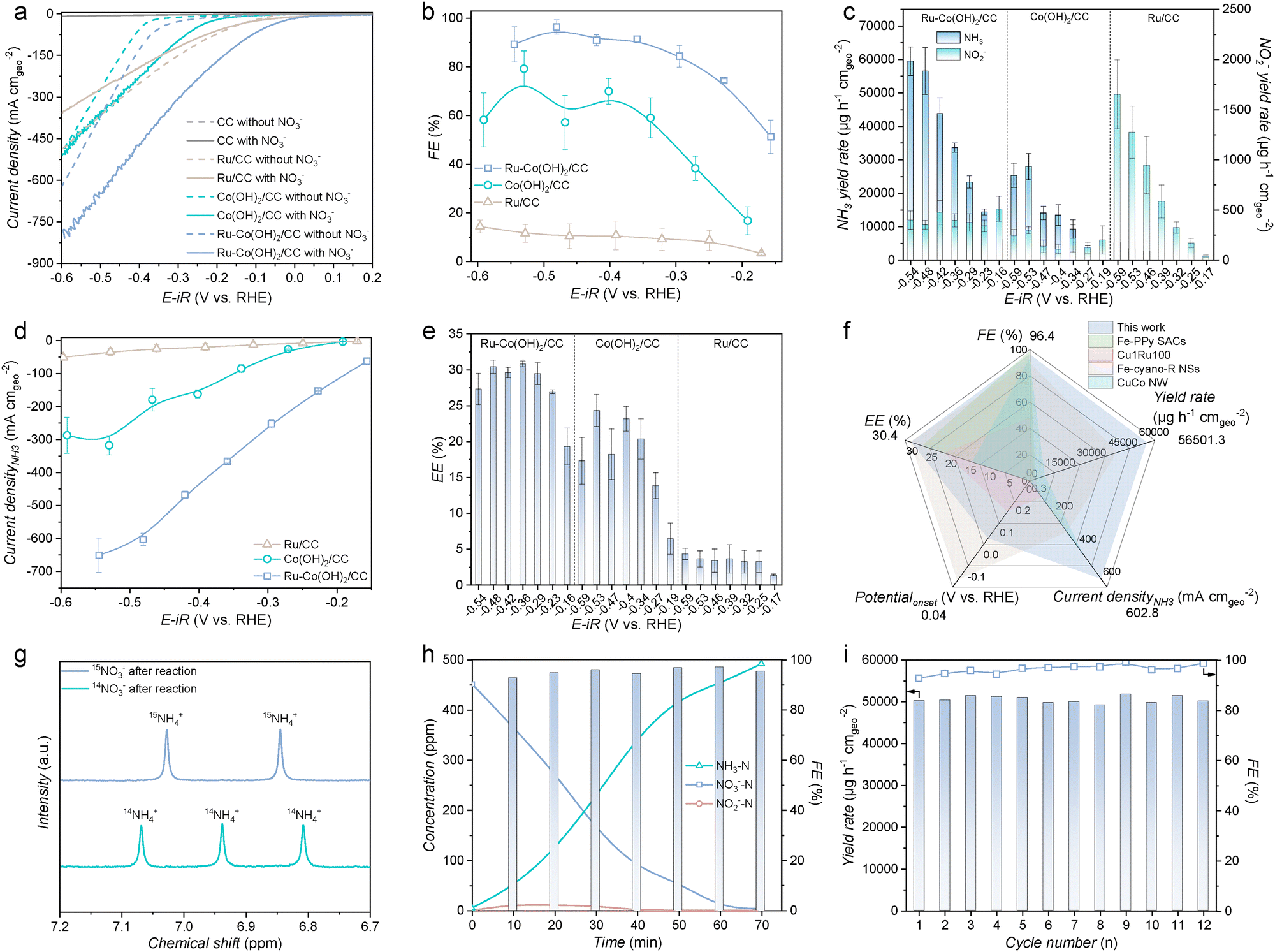
The synthesized samples were evaluated for the NO3RR in an Ar-saturated 1 M KOH solution with or without the NO3− electrolyte. A NO3− concentration of 2000 ppm, which is representative of industrial wastewater levels, was employed in the electrolyte.37 All linear sweep voltammetry (LSV) curves were obtained after repeated CV cycling until stabilization, ensuring the complete phase transition of materials. The LSV curve of Ru–Co(OH)2/CC exhibits superior NO3RR performance, with a large current density (Fig. 2a). EIS analysis confirmed that Ru–Co(OH)2/CC exhibited minimal charge transfer resistance, signifying its high efficiency in electron transfer (Fig. S10, ESI†). Ru–Co(OH)2/CC also exhibits an enhanced electrochemical active surface area (ECSA) (Fig. S11, ESI†), as evidenced by the double-layer capacitance obtained from cyclic voltammograms, indicating that Co(OH)2 nanosheets doped with Ru process the maximum reactive area.38 Moreover, the ECSA-normalized current density of Ru–Co(OH)2/CC was higher than that of Co(OH)2/CC (Fig. S12, ESI†), indicating that the superior NO3RR performance arises from an intrinsic activity induced by Ru doping rather than an enlarged surface area.39 A NO3RR performance comparison of Ru–Co(OH)2/CC prepared using RuCl3 solution concentrations of 0.2, 1, 5, and 10 mM during the ion-exchange process was systematically conducted. Among the tested samples, Ru-5-Co(OH)2/CC exhibited the lowest Tafel slope of 145.2 mV dec−1 (Fig. S13, ESI†), indicating the most efficient electron transfer kinetics during the NO3RR. The enhanced NO3RR activity of Ru-5-Co(OH)2/CC is also attributed to its reduced charge transfer resistance, as demonstrated in Fig. S14. In this study, NH3, NO2−, and residual NO3− were quantified using UV-vis spectrophotometry (Fig. S15–S17, ESI†). As shown in Fig. S18 (ESI†), Ru-5-Co(OH)2/CC maintained high NH3 yield rates and FEs across a wide potential range, outperforming other Ru-x-Co(OH)2/CC electrodes. Consequently, a 5 mM ion-exchange concentration was selected as the optimal synthesis condition. A control sample of commercial Ru nanoparticles on carbon cloth (Ru/CC) was also characterized (Fig. S19, ESI†). Additional samples with alternative noble metal dopants, including Pd, Ir, and Rh, were also prepared and characterized (Fig. S20–S22, ESI†). As shown in Fig. S23 and S24 (ESI†), Ru–Co(OH)2/CC consistently outperformed Pd–Co(OH)2/CC, Ir–Co(OH)2/CC, and Rh–Co(OH)2/CC in terms of the current density, NH3 yield rate, and NH3 FE. Fig. 2b shows the potential-dependent NH3 FEs obtained for Ru–Co(OH)2/CC, Co(OH)2/CC, and Ru/CC. Remarkably, Ru–Co(OH)2/CC achieved a maximum NH3 FE of ∼96% at −0.48 V and sustained a high FE across a broad potential window, significantly outperforming Co(OH)2/CC. The NH3 yield rates shown in Fig. 2c further demonstrate the enhanced NH3 yield rate of Ru–Co(OH)2/CC. With increasingly negative applied potentials, Ru–Co(OH)2/CC delivered a high NH3 yield rate of ∼56501 μg h−1 cmgeo−2 with a large NH3 partial current density of −602.8 mA cmgeo−2 at −0.48 V vs. RHE, outperforming Co(OH)2/CC (27857.3 μg h−1 cmgeo−2) and Ru/CC (3244.3 μg h−1 cmgeo−2) (Fig. 2d). The onset potential and half-cell energy efficiency (EE) of Ru–Co(OH)2/CC were 0.04 V vs. RHE and 30.4%, respectively, both significantly more favorable than those of Co(OH)2/CC (−0.15 V vs. RHE and 24.3%) and Ru/CC (−0.08 V vs. RHE and 3.5%) (Fig. 2e and Fig. S25, ESI†). The key performance parameters are summarized in Fig. 2f and Table S1 (ESI†), alongside comparisons with recent reports. To eliminate the potential interference from the electrocatalyst or external environment, we performed isotope-labeling experiments using 15N-labeled NO3− as the reagent. Unlike 14NH4+, which exhibited three peaks in the 1H NMR spectra, only the characteristic doublet peaks of 15NH4+ were observed when 15NO3− was used as the nitrogen source (Fig. 2g). This result confirms that NH3 production resulted from NO3− in the electrolyte. The NMR-derived 14NH3 yield rates were consistent with UV-vis results (Fig. S26, ESI†), confirming the reliability of the quantification methods. To demonstrate the broad adaptability of Ru–Co(OH)2/CC, we evaluated its performance across a range of NO3− concentrations. In addition to the 2000 ppm (32.3 mM) level, we selected 10 mM and 100 mM NO3− to represent typical NO3− concentrations found in household wastewater and heavy industrial effluents, respectively. Remarkably, Ru–Co(OH)2/CC achieved impressive NH3 FEs of 85.8% and 98.9% in an Ar-saturated 1 M KOH solution containing 10 mM and 100 mM NO3−, respectively (Fig. S27, ESI†). Moreover, the catalytic activity of the Ru–Co(OH)2/CC under the neutral conditions was further evaluated. Such Ru–Co(OH)2/CC exhibited a comparable NH3 yield rate (7279.07 μg h−1 cmgeo−2) and FE (88.5%) to that of under the alkaline conditions (Fig. S28, ESI†). To assess its practical viability, the NO3− removal capacity in simulated wastewater containing 2000 ppm NO3− was evaluated (Fig. 2h and Fig. S29, ESI†). Notably, NO3− and NO2− were reduced to levels below the World Health Organization drinking water standards within 70 min, while maintaining the NH3 FE above 90%, demonstrating excellent NO3− wastewater treatment capabilities.40 This rapid and efficient reduction highlights the potential of Ru–Co(OH)2/CC for real-world applications in wastewater treatment. Furthermore, the durability of Ru–Co(OH)2/CC for the NO3RR was confirmed through consecutive electrolysis cycles. As shown in Fig. 2i, the NH3 yield rates and FEs were consistently maintained over 12 cycles, indicating good stability. XRD, high-resolution X-ray photoelectron spectroscopy, SEM, and TEM analyses further demonstrated the high stability of Ru–Co(OH)2/CC during the NO3RR (Fig. S30–S33, ESI†).
 |
| | Fig. 2 Electrocatalytic NO3RR performance. (a) Polarization curves of Ru–Co(OH)2/CC, Co(OH)2/CC, Ru/CC, and CC measured with and without 2000 ppm NO3− in Ar-saturated 1 M KOH solution. (b) FEs of NH3 and the (c) yield rates of NH3 and NO2− for Ru–Co(OH)2/CC, Co(OH)2/CC, and Ru/CC. (d) Partial current densities and (e) energy efficiency of NH3 for Ru–Co(OH)2/CC, Co(OH)2/CC, and Ru/CC. (f) Comparison of NO3RR performance over Ru–Co(OH)2/CC with recently reported catalysts. (g) NMR spectra of the products generated during the NO3RR with Ru–Co(OH)2/CC in Ar-saturated 1 M KOH with 2000 ppm K15NO3 or 2000 ppm K14NO3 at −0.48 V vs. RHE. (h) The time-dependent concentration of NO3−, NO2−, and NH3 over Ru–Co(OH)2/CC at −0.48 V vs. RHE. (i) NH3 yield rates and FEs on Ru–Co(OH)2/CC under the potential of −0.48 V vs. RHE during 12 periods of the 30-min NO3RR. | |
Reaction mechanism analysis
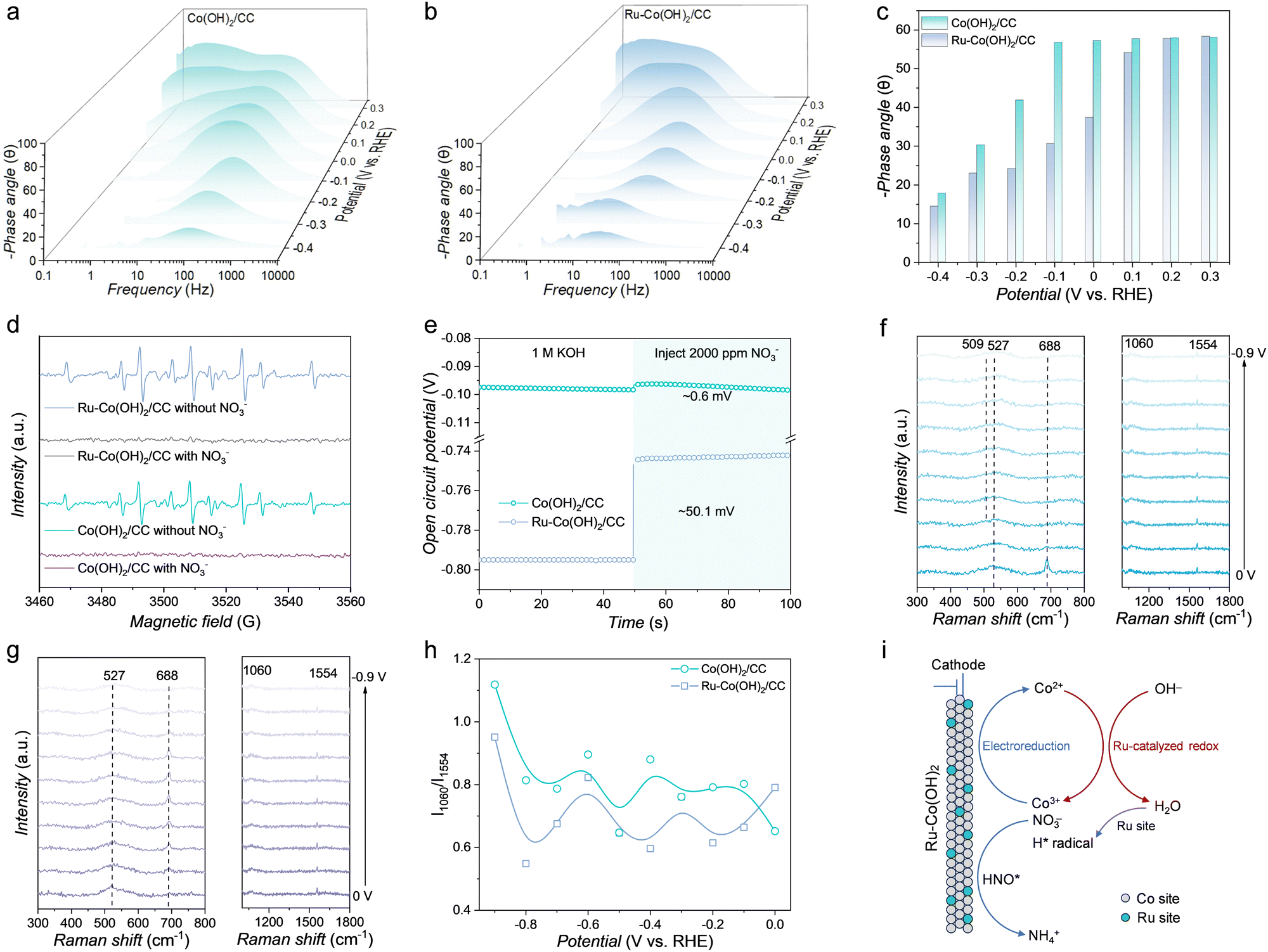
To analyze the properties of electrode/electrolyte interfaces during the NO3RR, operando EIS measurements were performed at different potentials. As shown in Fig. S34 (ESI†), the cathodic resistance comprises four components. The generation of H* via water dissociation (Volmer step) occurs in the low-frequency range (<100 Hz), whereas the subsequent consumption of H* (Heyrovsky step) occurs in the middle-frequency range (100 to 102 Hz).41 The charge-transfer resistance observed in the Nyquist plots of Ru–Co(OH)2/CC is smaller than that of Co(OH)2/CC under the same bias, indicating that Ru–Co(OH)2/CC exhibits a faster charge transfer rate during the NO3RR (Fig. S35, ESI†).42 As reported, the phase angle provides insights into the proportion of charges participating in the catalytic process, where smaller phase angles indicate a higher involvement of charges in the faradaic process.43 The peak intensities of Ru–Co(OH)2/CC are lower than those of Co(OH)2/CC and shift to much lower frequencies from 0.1 to −0.4 V vs. RHE (Fig. 3a and b). This shift confirms that Ru doping not only slows the Heyrovsky step but also inhibits H2 generation,44 enabling more efficient capture of H* by NO3− for NH3 formation. As shown in Fig. 3c, within the potential window of 0.3 to −0.4 V vs. RHE, the smaller phase angles of Ru–Co(OH)2/CC in the middle-frequency region (around 101 to 102 Hz) demonstrate enhanced charge transfer and fast NO3RR kinetics, directly attributable to the effect of Ru doping.45 Further insights were obtained using quasi EPR spectroscopy to investigate the generation and consumption of hydrogen radicals during the NO3RR. As shown in Fig. 3d, after electrolysis in Ar-saturated 1 M KOH solution, Ru–Co(OH)2/CC exhibits significantly stronger DMPO–H signals than Co(OH)2/CC, indicating that Ru–Co(OH)2/CC favors water dissociation and promotes the formation of active hydrogen necessary for protonation. While Co(OH)2/CC exhibited slightly reduced DMPO–H signals, nearly all DMPO–H signals for Ru–Co(OH)2/CC disappeared, suggesting the rapid consumption of hydrogen radicals on Ru–Co(OH)2/CC to enhance NO3RR hydrogenation energetics. The open-circuit potential (OCP), which reflects changes in absorbates within the Helmholtz layer, was measured to evaluate the NO3− adsorption behavior (Fig. 3e).46 A significant decrease in the OCP (∼50.1 mV) was observed for Ru–Co(OH)2/CC after adding 2000 ppm NO3−, compared to that for Co(OH)2/CC (∼0.6 mV), indicating that Ru doping enhances NO3− adsorption on the catalyst. To investigate surface phase evolution, in situ Raman spectroscopy was conducted at various applied potentials (Fig. S36, ESI†). For Ru–Co(OH)2/CC (Fig. 3f), the stretching vibration peak at 527 cm−1, attributed to Co(OH)2, was observed. At −0.2 V vs. RHE, a new peak at 509 cm−1, corresponding to CoO(OH), appeared, suggesting partial oxidation of Co2+ to Co3+.47,48 In contrast, the Raman spectra of Co(OH)2/CC showed no CoO(OH)-related peaks, with the Co(OH)2 peak at 527 cm−1 remaining unchanged across applied potentials (Fig. 3g). Additionally, the Raman peaks at 688 cm−1, corresponding to the Co–O vibration, diminished with increasingly negative potentials (0 V to −0.9 V vs. RHE). This phenomenon was also observed in Ar-saturated 1 M KOH solution (Fig. S37, ESI†). However, for Ru–Co(OH)2/CC, the Co(OH)2 peak at 688 cm−1 disappeared after immersion in Ar-saturated 1 M KOH solution with 2000 ppm NO3−, accompanied by the emergence of a CoO(OH) peak at 509 cm−1. No CoO(OH) peaks were observed for Co(OH)2/CC under similar conditions, implying that Ru promotes Co(OH)2 oxidation in the presence of high OH− concentrations (Fig. S38, ESI†). A peak at 1060 cm−1, corresponding to the symmetric stretching vibration of NO3−, was present across applied potentials (Fig. 3f and g).49 Additionally, a peak at 1554 cm−1, attributed to the N–O stretch of HNO, emerged as the potential shifted negatively to −0.9 V vs. RHE.50 As shown in Fig. 3h and Table S2 (ESI†), the intensity ratio of the peak at 1060 cm−1 and 1554 cm−1 (I1060/I1554) for Ru–Co(OH)2/CC was consistently lower than that of Co(OH)2/CC across the potential range of −0.2 to −0.9 V vs. RHE, indicating more efficient conversion of NO3− to the HNO species. As shown in Fig. 3i, Ru sites facilitate the generation of hydrogen radicals during the NO3RR, thereby providing sufficient protons for NO3− hydrogenation. Concurrently, under the influence of Ru, the neighboring Co(OH)2 is oxidized by the OH− to form high-valence CoO(OH) (Co(OH)2 + OH− → CoO(OH) + H2O + e−), which serves as an active site for converting NO3− to the HNO species. This synergistic interaction between Ru and CoO(OH) ultimately facilitates efficient NH3 synthesis.
 |
| | Fig. 3
Operando characterization and the mechanism of the phase transition. Bode phase plots of (a) Co(OH)2/CC and (b) Ru–Co(OH)2/CC at varied potentials in Ar-saturated 1 M KOH solution with 2000 ppm NO3−. (c) Phase peak angles of Co(OH)2/CC and Ru–Co(OH)2/CC at 0.3 to −0.4 V vs. RHE. (d) Quasi in situ EPR trapping of hydrogen radicals. (e) OCP curves of Ru–Co(OH)2/CC and Co(OH)2/CC in Ar-saturated 1 M KOH and 2000 ppm NO3− was injected subsequently. In situ Raman spectra of (f) Ru–Co(OH)2/CC and (g) Co(OH)2/CC at different applied potentials in Ar-saturated 1 M KOH solution with 2000 ppm NO3−. (h) I1060/I1554 for Ru–Co(OH)2/CC and Co(OH)2/CC at different applied potentials. (i) Proposed mechanism of NH3 synthesis from the electrochemical reduction of NO3− over Ru–Co(OH)2/CC. | |
Theoretical simulations
We further employed density functional theory (DFT) calculations to investigate the improved NO3RR performance of the Ru–Co(OH)2 catalyst by constructing a Ru–Co(OH)2 model (Fig. 4a). The electronic structures of Co(OH)2 and Ru–Co(OH)2 were analyzed to elucidate the catalytic activity enhancement resulting from Ru doping. The electron location function (ELF) revealed increased localization near Ru atoms compared to Co(OH)2, indicating stronger electron exchange between Ru–Co(OH)2 and adsorbed NO3− (Fig. 4b). The density of states (DOS) analysis (Fig. 4c) demonstrated that Ru doping shifted the occupied electron states closer to the Fermi energy level, resulting in a higher DOS for Ru–Co(OH)2. The d-band centers of Co(OH)2 and Ru–Co(OH)2 were −2.26 and −2.12 eV, respectively. This upward shift in the d-band center for Ru–Co(OH)2 was primarily attributed to the enhanced electronic states of Ru dyz and dz2−y2 orbitals near the Fermi level (Fig. S39 and S40, ESI†). Based on the d-band center theory, a higher d-band center indicates stronger interactions with intermediates, highlighting the improved catalytic potential of Ru–Co(OH)2.51,52 The differential charge density and Bader charge analyses (Fig. 4d) further investigated the charge transfer processes between Ru/Co and NO3 species in Co(OH)2 and Ru–Co(OH)2. The results indicated a significant charge redistribution around Ru atoms at the Ru–Co(OH)2 interface, with greater charge transfer to adsorbed NO3− compared to Co(OH)2, Specifically, Co atoms in Co(OH)2 transferred 0.39 electrons to nearby O atoms, while Ru atoms in Ru–Co(OH)2 transferred a total of 1.02 electrons to the surrounding O atoms (Fig. S41, ESI†). Combined with ELF findings, this suggests that Ru atoms enhance interfacial electron aggregation and promote efficient transfer to adsorbed intermediates, boosting catalyst performance.
 |
| | Fig. 4 Theoretical calculation analysis. (a) The top view (top) and side view (bottom) of the Ru–Co(OH)2 model. (b) The electron location function and (c) density of states of Co(OH)2 and Ru–Co(OH)2. (d) Differential charge density of *NO3 of Co(OH)2 and Ru–Co(OH)2. The isosurface value is set to be 0.02 e Å−3, and the consumption and accumulation of charges are shown in yellow and cyan, respectively. (e) Reaction free-energy diagram of Co(OH)2 and Ru–Co(OH)2 for the NO3RR. Schematic of the electrochemical NO3RR toward NH3 for (f) Co(OH)2 and (g) Ru–Co(OH)2. (h) Partial density of states of Co–N atoms and Ru–N atoms of the *HNO intermediate over Co(OH)2 and Ru–Co(OH)2. | |
According to thermodynamic calculations, the adsorption free energy of NO3− on Ru–Co(OH)2 was −2.95 eV, compared to −2.46 eV for Co(OH)2, indicating that Ru doping improves the thermodynamic favorability of NO3− adsorption (Fig. S42, ESI†). Bader charge analysis verifies the higher oxidation states of the Co species in Ru–Co(OH)2 (Fig. S43 and Table S3, ESI†). Additionally, Fig. 4e shows that the rate-determining step (RDS) for Co(OH)2 in the NO3RR is the transformation of *NO2 into *NO, with an energy barrier of 0.78 eV. In contrast, Ru doping alters the RDS to the transition from *HNO to *H, significantly reducing the energy barrier to 0.64 eV (Fig. S44 and S45, and Table S4, ESI†). This shift in the RDS implies that the accumulation of *HNO on Ru–Co(OH)2, due to restricted *HNO dissociation, aligns with in situ Raman spectroscopy observations. DFT calculations were performed to assess the competitive hydrogen evolution reaction (HER) pathway on Ru–Co(OH)2. As shown in Fig. S46–S48 (ESI†), the energy barrier for the HER step (*H → ½H2) is 1.29 eV, higher than the 0.64 eV for the NO3RR rate-determining step. This suggests a kinetic preference for NO3− reduction over the HER. Overall, the incorporation of Ru atoms modulates the electronic structure of the Co(OH)2 active site, enhances electron transfer, improves NO3− adsorption, and facilitates the conversion of *NO2 intermediates. The incorporation of Ru significantly enhances the Ru–N interaction in the *HNO intermediate, effectively modulating the reaction pathway and the RDS (Fig. 4f and g). The partial density of states (PDOS) analysis of the *HNO intermediate over Co(OH)2 and Ru–Co(OH)2 further elucidates the underlying mechanism. As shown in Fig. 4h, the dxz and dγz orbitals of Ru, in comparison with Co(OH)2 exhibit substantial orbital coupling with the px and py orbitals of the N atoms in the unoccupied states (∼2 eV). Moreover, in the occupied states (∼−3 eV), the Ru dxz and dγz orbitals display strong coupling with the N px and py orbitals, respectively. This orbital coupling significantly enhances the adsorption stability of the *HNO intermediate on Ru–Co(OH)2.
Potential industrial application
To demonstrate the industrial potential for the NO3RR under ambient conditions, we assembled an NO3RR-OER MEA electrolyzer with Ru–Co(OH)2/CC (2 × 2 cm2) as the cathode and IrO2 on platinum-coated titanium felt (IrO2/PTF) (2 × 2 cm2) as the anode (Fig. 5a). The PTF substrate was chosen for its excellent electrical conductivity and corrosion resistance, while the platinum coating mitigates the surface passivation of titanium, thereby ensuring stable interfacial conductivity during long-term operation.53 The Ru–Co(OH)2/CC‖IrO2/PTF MEA exhibited significantly reduced resistance and achieved an industrial current density of 500 mA cm−2 at 2.6 V, markedly outperforming the Co(OH)2/CC‖IrO2/PTF device (∼280 mA cm−2 at 2.6 V) (Fig. 5b and Fig. S49, ESI†). To ensure consistent NO3− conversion, we optimized the flow rate (Fig. S50, ESI†). Using the MEA electrolyzer with Ru–Co(OH)2/CC as the cathode, NO3− was converted to NH3 with a FE of 94 ± 6% and a yield rate of 7472 ± 487 μg h−1 cmgeo−2 at 100 mA cm−2, demonstrating excellent potential for NH3 production (Fig. 5c and Fig. S51, ESI†). The stability of the MEA system was further investigated, and it maintained an average NH3 FE of ∼93%, an NH3 yield rate of ∼7000 μg h−1 cmgeo−2, and a voltage of 1.9 V at 100 mA cm−2 for over 100 h (Fig. 5d). The minor voltage fluctuations observed are attributed to electrolyte replenishment, necessary to compensate for nitrate depletion and maintain consistent reaction conditions.
 |
| | Fig. 5 Practical NH3 product synthesis. (a) Schematic of a MEA cell for the NO3RR. (b) Polarization curves of the MEA cell with Ru–Co(OH)2/CC and Co(OH)2/CC cathodes, paired with an IrO2/PTF anode. (c) NH3 FEs and yield rates of the Ru–Co(OH)2/CC over a broad range of current densities in the MEA. (d) Stability of the MEA system at 100 mA cm−2, tracking NH3 FEs, yield rates, and the cell voltage using a Ru–Co(OH)2/CC cathode and an IrO2/PTF anode. (e) XRD pattern of the synthesized NH4Cl product (the inset is the photograph of the synthesized NH4Cl product). (f) Estimated costs for the NO3RR in the MEA system. (g) Contour map illustrating NH3 synthesis costs as a function of current densities and electricity prices. | |
To confirm the practical potential for NH3 production, a high-purity NH3 product was collected after NO3− electroreduction using an acid trap method (Fig. S52–S54, ESI†).54 The successful production of NH4Cl is confirmed by the XRD pattern in Fig. 5e and the related elemental mapping results in Fig. S55 (ESI†). Building on this promising performance, a TEA was conducted to evaluate the feasibility and the potential for commercialization (Note S1, ESI†). As shown in Fig. S56 (ESI†), the estimated total cost of NH3 production using the MEA electrolyzer was approximately US$ 1.995 per kg NH3. This system demonstrates high viability, particularly when considering the potential profitability of NO3− wastewater treatment. The major cost contributions are the electricity consumption (39.12%), electrolytic cell (26.94%), and balance of plant (14.5%) (Fig. 5f). Optimizing the electrolyzer design and reducing electricity costs could significantly enhance the economic potential of converting NO3− wastewater into NH3. The TEA analysis used an industrial electricity price of US$0.03 kW h in this study,55 and further cost reductions could be achieved by leveraging excess renewable energy from wind or solar sources. The relationship between the electricity cost and current density is illustrated in the contour map (Fig. 5g). Notably, if electricity costs drop below US$0.03 kW h in the future, the total cost of NH3 production via this MEA system could fall below the current market price of NH3 produced by the Haber–Bosch process (US$1.15 per kg NH3)56 at current densities below 300 mA cm−2, even before accounting for additional profits from wastewater treatment.
Conclusions
In summary, we report the dynamic structural evolution of Ru–Co(OH)2/CC as an efficient electrode for the NO3RR, identifying Co(III) sites as the crucial active sites for NH3 generation. The optimal Ru–Co(OH)2/CC attains a high NH3 FE of ∼96% and a large yield rate of ∼56501 μg h−1 cmgeo−2 in 1 M KOH solution with 2000 ppm NO3−. Ex situ XAS and XRD analyses reveal a dynamic evolution of Co(III) sites on the Ru–Co(OH)2/CC during the NO3RR. In situ Raman spectroscopy and EPR spectroscopy demonstrate that Ru doping facilitates the generation of hydrogen radicals, which promote the hydrogenation of *HNO intermediates on adjacent Co(III) sites. Economic modeling underscores the techno-economic feasibility of the NO3RR, presenting it as a greener alternative for NH3 synthesis and NO3− wastewater treatment. This study not only provides an effective strategy to design and construct Co-based catalysts for the NO3RR, but also unveils the crucial role of Co(III) sites for sustainable ammonia electrosynthesis.
Author contributions
L. Z., X. G., and Z. J. X. conceived the original concept and initiated the project. L. Z. wrote the manuscript. Y. L. carried out the theoretical calculations. L. Z. synthesized the materials and performed the characterization with assistance from S. X. (XAS), L. T. (XPS), J. Z. Y. S. (XRD), and S. S. (NMR). L. L. performed in situ Raman measurements. T. W., Q. W., X. L., K. T., and D. S. performed the data analysis. All authors contributed to the discussion of the manuscript.
Data availability
The data that support the findings in this study are available from the corresponding author upon reasonable request.
Conflicts of interest
There are no conflicts to declare.
Acknowledgements
This work was supported by the Singapore Ministry of Education Tier 2 Grant (MOE-T2EP10223-0006) and Tier 1 Grant (RG91/23), the National Natural Science Foundation of China (22425804), the Natural Science Foundation of Sichuan Province (2025ZNSFSC0899 and 2025ZNSFSC0923), and the Postdoctoral Joint Training Program of Sichuan University (SCDXLHPY2303). The authors thank Dr. Feng Yang (the Comprehensive Training Platform of the Specialized Laboratory, College of Chemistry, Sichuan University) for her assistance with TEM characterization and Prof. Li Wu (Analytical & Testing Center, Sichuan University) for her help with in situ Raman spectroscopy.
References
- C. H. Christensen, T. Johannessen, R. Z. Sørensen and J. K. Nørskov, Catal. Today, 2006, 111, 140–144 CrossRef CAS.
- J. G. Chen, R. M. Crooks, L. C. Seefeldt, K. L. Bren, R. M. Bullock, M. Y. Darensbourg, P. L. Holland, B. Hoffman, M. J. Janik, A. K. Jones, M. G. Kanatzidis, P. King, K. M. Lancaster, S. V. Lymar, P. Pfromm, W. F. Schneider and R. R. Schrock, Science, 2018, 360, eaar6611 CrossRef PubMed.
- Mineral Commodity Summaries 2022 (US Geological Survey, 2022).
- M. Wang, M. A. Khan, I. Mohsin, J. Wicks, A. H. Ip, K. Z. Sumon, C.-T. Dinh, E. H. Sargent, I. D. Gates and M. G. Kibria, Energy Environ. Sci., 2021, 14, 2535–2548 RSC.
- L. Zhang, J. Liang, Y. Wang, T. Mou, Y. Lin, L. Yue, T. Li, Q. Liu, Y. Luo, N. Li, B. Tang, Y. Liu, S. Gao, A. A. Alshehri, X. Guo, D. Ma and X. Sun, Angew. Chem., Int. Ed., 2021, 60, 25263–25268 CrossRef CAS.
- W. Qiu, X.-Y. Xie, J. Qiu, W.-H. Fang, R. Liang, X. Ren, X. Ji, G. Cui, A. M. Asiri, G. Cui, B. Tang and X. Sun, Nat. Commun., 2018, 9, 3485 CrossRef.
- X. Fu, V. A. Niemann, Y. Zhou, S. Li, K. Zhang, J. B. Pedersen, M. Saccoccio, S. Z. Andersen, K. Enemark-Rasmussen, P. Benedek, A. Xu, N. H. Deissler, J. B. V. Mygind, A. C. Nielander, J. Kibsgaard, P. C. K. Vesborg, J. K. Nørskov, T. F. Jaramillo and I. Chorkendorff, Nat. Mater., 2024, 23, 101–107 CrossRef CAS.
- B. H. R. Suryanto, H.-L. Du, D. Wang, J. Chen, A. N. Simonov and D. R. MacFarlane, Nat. Catal., 2019, 2, 290–296 CrossRef CAS.
- C. Tang and S.-Z. Qiao, Chem. Soc. Rev., 2019, 48, 3166–3180 RSC.
- Y. Wang, C. Wang, M. Li, Y. Yu and B. Zhang, Chem. Soc. Rev., 2021, 50, 6720–6733 RSC.
- J. Liang, Z. Li, L. Zhang, X. He, Y. Luo, D. Zheng, Y. Wang, T. Li, H. Yan, B. Ying, S. Sun, Q. Liu, M. S. Hamdy, B. Tang and X. Sun, Chem, 2023, 9, 1768–1827 CAS.
- H. Zhu, J. J. Wang, Z. Xu, Y. Tan and J. Wang, Small, 2024, 20, 2404919 CrossRef CAS.
- G.-F. Chen, Y. Yuan, H. Jiang, S.-Y. Ren, L.-X. Ding, L. Ma, T. Wu, J. Lu and H. Wang, Nat. Energy, 2020, 5, 605–613 CrossRef CAS.
- Y. Wang, A. Xu, Z. Wang, L. Huang, J. Li, F. Li, J. Wicks, M. Luo, D.-H. Nam, C.-S. Tan, Y. Ding, J. Wu, Y. Lum, C.-T. Dinh, D. Sinton, G. Zheng and E. H. Sargent, J. Am. Chem. Soc., 2020, 142, 5702–5708 CrossRef CAS PubMed.
- S. Sun, C. Dai, P. Zhao, S. Xi, Y. Ren, H. R. Tan, P. C. Lim, M. Lin, C. Diao, D. Zhang, C. Wu, A. Yu, J. C. J. Koh, W. Y. Lieu, D. H. L. Seng, L. Sun, Y. Li, T. L. Tan, J. Zhang, Z. J. Xu and Z. W. Seh, Nat. Commun., 2024, 15, 260 CrossRef CAS PubMed.
- Z.-Y. Wu, M. Karamad, X. Yong, Q. Huang, D. A. Cullen, P. Zhu, C. Xia, Q. Xiao, M. Shakouri, F.-Y. Chen, J. Y. Kim, Y. Xia, K. Heck, Y. Hu, M. S. Wong, Q. Li, I. Gates, S. Siahrostami and H. Wang, Nat. Commun., 2021, 12, 2870 CrossRef CAS PubMed.
- P. Wang, C. Liu, L. Rao, W. Tao, R. Huang, P. Huang and G. Zhou, Energy Environ. Sci., 2024, 17, 6698–6706 RSC.
- P. H. van Langevelde, I. Katsounaros and M. T. M. Koper, Joule, 2021, 5, 290–294 CrossRef.
- M. J. Ascott, D. C. Gooddy, L. Wang, M. E. Stuart, M. A. Lewis, R. S. Ward and A. M. Binley, Nat. Commun., 2017, 8, 1416 CrossRef CAS.
- Q. Liu, L. Xie, J. Liang, Y. Ren, Y. Wang, L. Zhang, L. Yue, T. Li, Y. Luo, N. Li, B. Tang, Y. Liu, S. Gao, A. A. Alshehri, I. Shakir, P. O. Agboola, Q. Kong, Q. Wang, D. Ma and X. Sun, Small, 2022, 18, 2106961 CrossRef CAS PubMed.
- S. Liang, X. Teng, H. Xu, L. Chen and J. Shi, Angew. Chem., Int. Ed., 2024, 63, e202400206 CrossRef CAS.
- Q. Yan, R. Zhao, L. Yu, Z. Zhao, L. Liu and J. Xi, Adv. Mater., 2024, 36, 2408680 CrossRef CAS.
- X. Deng, Y. Yang, L. Wang, X.-Z. Fu and J.-L. Luo, Adv. Sci., 2021, 8, 2004523 CrossRef CAS PubMed.
- L. Qiao, A. Zhu, D. Liu, K. An, J. Feng, C. Liu, K. W. Ng and H. Pan, Adv. Energy Mater., 2024, 14, 2402805 CrossRef CAS.
- S. Han, H. Li, T. Li, F. Chen, R. Yang, Y. Yu and B. Zhang, Nat. Catal., 2023, 6, 402–414 CrossRef CAS.
- T. Wu, S. Sun, J. Song, S. Xi, Y. Du, B. Chen, W. A. Sasangka, H. Liao, C. L. Gan, G. G. Scherer, L. Zeng, H. Wang, H. Li, A. Grimaud and Z. J. Xu, Nat. Catal., 2019, 2, 763–772 CrossRef CAS.
- Y. Sun, J. Wang, S. Xi, J. Shen, S. Luo, J. Ge, S. Sun, Y. Chen, J. V. Hanna, S. Li, X. Wang and Z. J. Xu, Nat. Commun., 2023, 14, 2467 CrossRef CAS PubMed.
- T. Wu, Y. Sun, X. Ren, J. Wang, J. Song, Y. Pan, Y. Mu, J. Zhang, Q. Cheng, G. Xian, S. Xi, C. Shen, H.-J. Gao, A. C. Fisher, M. P. Sherburne, Y. Du, J. W. Ager, J. Gracia, H. Yang, L. Zeng and Z. J. Xu, Adv. Mater., 2023, 35, 2207041 CrossRef CAS.
- E. Fabbri, M. Nachtegaal, T. Binninger, X. Cheng, B.-J. Kim, J. Durst, F. Bozza, T. Graule, R. Schäublin, L. Wiles, M. Pertoso, N. Danilovic, K. E. Ayers and T. J. Schmidt, Nat. Mater., 2017, 16, 925–931 CrossRef CAS.
- L.-W. Jiang, Y. Huang, Y. Zou, C. Meng, Y. Xiao, H. Liu and J.-J. Wang, Adv. Energy Mater., 2022, 12, 2202351 CrossRef CAS.
- F. T. Haase, A. Bergmann, T. E. Jones, J. Timoshenko, A. Herzog, H. S. Jeon, C. Rettenmaier and B. R. Cuenya, Nat. Energy, 2022, 7, 765–773 CrossRef CAS.
- Q. Zhou, Q. Bian, L. Liao, F. Yu, D. Li, D. Tang and H. Zhou, Chin. Chem. Lett., 2023, 34, 107248 CrossRef CAS.
- H. Jia, N. Yao, Z. Liao, L. Wu, J. Zhu, Y. Lao and W. Luo, Angew. Chem., Int. Ed., 2024, 63, e202408005 CrossRef CAS.
- X.-Z. Yue, P. Tang, X. Du, W.-J. Yi, Z.-Y. Liu, S.-J. Wang and S.-S. Yi, ACS Appl. Mater. Interfaces, 2023, 15, 11621–11630 CrossRef CAS.
- H. Jin, K. Zhou, R. Zhang, H. Cui, Y. Yu, P. Cui, W. Song and C. Cao, Nat. Commun., 2023, 14, 2494 CrossRef CAS PubMed.
- S. Wang, Q. Jiang, S. Ju, C.-S. Hsu, H. M. Chen, D. Zhang and F. Song, Nat. Commun., 2022, 13, 6650 CrossRef CAS PubMed.
- Y. Fernández-Nava, E. Marañón, J. Soons and L. Castrillón, Bioresour. Technol., 2008, 99, 7976–7981 CrossRef.
- C. Wei, S. Sun, D. Mandler, X. Wang, S. Z. Qiao and Z. J. Xu, Chem. Soc. Rev., 2019, 48, 2518–2534 RSC.
- C. Wei, R. R. Rao, J. Peng, B. Huang, I. E. L. Stephens, M. Risch, Z. J. Xu and Y. Shao-Horn, Adv. Mater., 2019, 31, 1806296 CrossRef.
- S. Garcia-Segura, M. Lanzarini-Lopes, K. Hristovski and P. Westerhoff, Appl. Catal., B, 2018, 236, 546–568 CrossRef CAS.
- H. Xu, G. Xu, B. Huang, J. Yan, M. Wang, L. Chen and J. Shi, Angew. Chem., Int. Ed., 2023, 62, e202218603 CrossRef CAS PubMed.
- H. Du, T. Sun, M. Wang, Y. Tang, Y. Yu and J. Wang, Chem. Commun., 2025, 61, 5719–5730 RSC.
- J. L. Gilbert and P. Khullar, J. Electrochem. Soc., 2020, 167, 021505 CrossRef CAS.
- J. Lv, A. Cao, Y. Zhong, Q. Lin, X. Li, H. B. Wu, J. Yan and A. Wu, Nat. Commun., 2024, 15, 6675 CrossRef CAS.
- Y. Feng, X. Wang, J. Ma, N. Wang, Q. Liu, K. Suenaga, W. Chen, J. Zhang, Y. Zhou and J. Wang, Adv. Energy Mater., 2024, 14, 2401501 CrossRef CAS.
- P. Zhou, X. Lv, S. Tao, J. Wu, H. Wang, X. Wei, T. Wang, B. Zhou, Y. Lu, T. Frauenheim, X. Fu, S. Wang and Y. Zou, Adv. Mater., 2022, 34, 2204089 CrossRef CAS.
- J. Yang, H. Liu, W. N. Martens and R. L. Frost, J. Phys. Chem. C, 2010, 114, 111–119 CrossRef CAS.
- W. He, J. Zhang, S. Dieckhöfer, S. Varhade, A. C. Brix, A. Lielpetere, S. Seisel, J. R. C. Junqueira and W. Schuhmann, Nat. Commun., 2022, 13, 1129 CrossRef CAS PubMed.
- M. Xu, J. P. Larentzos, M. Roshdy, L. J. Criscenti and H. C. Allen, Phys. Chem. Chem. Phys., 2008, 10, 4793–4801 RSC.
- Y. Ling, C. Mills, R. Weber, L. Yang and Y. Zhang, J. Am. Chem. Soc., 2010, 132, 1583–1591 CrossRef CAS PubMed.
- B. Hammer and J. K. Norskov, Nature, 1995, 376, 238–240 CrossRef CAS.
- B. Hammer and J. K. Nørskov, Surf. Sci., 1995, 343, 211–220 CrossRef CAS.
- S. Zhang, Z. Wang, R. Zhang, Y. He and K. Cen, Int. J. Hydrogen Energy, 2023, 48, 35463–35476 CrossRef CAS.
- M.-H. Yuan, Y.-H. Chen, J.-Y. Tsai and C.-Y. Chang, Process Saf. Environ. Prot., 2016, 102, 777–785 CrossRef CAS.
- Levelized cost and levelized avoided cost of new generation resources (EIA, 2020); https://www.eia.gov/outlooks/aeo/pdf/electricity_generation.pdf.
-
G. Schnitkey, et al. Fertilizer prices and company profits going into spring 2023. Farmdoc Daily, https://farmdocdaily.illinois.edu/2023/02/fertilizer-prices-and-company-profits-going-into-spring-2023.html (2023).
|
| This journal is © The Royal Society of Chemistry 2025 |
Click here to see how this site uses Cookies. View our privacy policy here. 
 Open Access Article
 This Open Access Article is licensed under a Creative Commons Attribution-Non Commercial 3.0 Unported Licence
 ab,
Yuan
Liu
b,
Ling
Li
ab,
Yuan
Liu
b,
Ling
Li