
 Open Access Article
 This Open Access Article is licensed under a
 Creative Commons Attribution 3.0 Unported Licence
Advancing geothermal energy utilization opportunities: potential and strategies for integrating direct air capture†
Maxwell
Pisciotta
 a,
Hélène
Pilorgé
a,
Likhwa
Ndlovu
a,
Madeleine
Siegel
b,
Joe
Huyett
b,
Todd
Bandhauer
b,
Peter
Psarras
a and
Jennifer
Wilcox
*a
a,
Hélène
Pilorgé
a,
Likhwa
Ndlovu
a,
Madeleine
Siegel
b,
Joe
Huyett
b,
Todd
Bandhauer
b,
Peter
Psarras
a and
Jennifer
Wilcox
*a
aUniversity of Pennsylvania, Chemical and Biomolecular Engineering Department, Philadelphia, Pennsylvania, USA. E-mail: mpisciot@seas.upenn.edu
bColorado State University, Mechanical Engineering Department, Fort Collins, Colorado, USA
First published on 18th June 2025
Abstract
Geothermal energy has been utilized for centuries. Prior to the industrial revolution, geothermal surface expressions were healing destinations in regions of Indigenous America, and geothermal energy was used to heat baths across the Roman empire and throughout Japan. Today, geothermal energy is harnessed for direct use in some industrial applications requiring low-grade heat as well as district heating systems, and for low-carbon electricity production, making up over 13 GW of worldwide electricity production. In the U.S., new legislation introduced incentives to promote geothermal energy as a baseload renewable electricity source. However, geothermal energy also has potential for CO2 abatement beyond electricity generation. For example, low temperature geothermal resources can be used directly for residential heating systems, industrial processes or to power direct air capture (DAC) systems. This study explores the potential of geothermal resources to meet the thermal and electrical demands of DAC systems through the development of a geothermal-DAC evaluation framework. The framework examines configurations where binary geothermal power plants and DAC units are engineered to optimize geothermal resource use. These configurations are evaluated based on their CO2 abatement potential, achieved by displacing carbon-intensive grid electricity and removing atmospheric CO2. The framework was applied to two hypothetical geothermal resources, representing low (86 °C) and high (225 °C) temperature regimes for binary geothermal power plants, considering various organic Rankine cycle (ORC) working fluids. It was also tested on the Raft River binary geothermal combined cycle power plant. Results show that integrating geothermal energy with DAC systems improves CO2 abatement potential compared to using geothermal resources solely for electricity. Improvements range from 5–757%, depending on the resource and configuration. Technoeconomic evaluations of each configuration determined the levelized cost of energy delivered to the DAC system (LCOEDAC), ranging from $101–8579 per tCO2. The geothermal-DAC evaluation framework highlights strategic decisions and constraints for integrating geothermal resources with DAC to maximize grid electricity production and CO2 abatement.
Broader contextThe transition to a low-carbon economy is a critical component of global efforts to combat climate change, with renewable energy and carbon removal technologies playing a key role in reducing overall greenhouse gas emissions in the atmosphere. In the U.S., recent legislation spurred broader economic incentives to promote the development and utilization of geothermal energy as an electricity source that could meet baseload, peaking, and load following needs for the grid. However, there may be other opportunities to leverage geothermal energy for CO2 abatement. Furthermore, for chemical-based carbon removal technologies like DAC to be the most impactful, they will require renewable energy for operation. In this study, utilizing geothermal energy to meet both thermal and electrical requirements of DAC is investigated. The results highlight that integrating binary geothermal power plants with DAC can increase the CO2 abatement potential by 5–757% compared to the generation of geothermal electricity alone, depending on the specific resource. Furthermore, this study evaluates the levelized cost of energy dedicated to DAC when it is sourced from a geothermal resource, illustrating its cost competitiveness. |
1. Introduction
It has been scientifically agreed upon that human activity, and specifically the release of greenhouse gasses into the atmosphere, is responsible for climate change.1 One of the prominent greenhouse gasses that has accumulated in the atmosphere since the industrial revolution is carbon dioxide (CO2). To cease the continued climatic environmental damage brought on by atmospheric CO2 emissions, these contributions need to be reduced, and CO2 emissions already present in the atmosphere need to be removed and permanently stored.‡ There are many ways to remove CO2 from the atmosphere, including those facilitated by nature, such as afforestation (tree planting in a region where trees were not planted before) or reforestation (tree planting where there were trees previously), and those facilitated by chemical reactions, such as direct air capture (DAC) and storage. Due to the dilute nature of CO2 in the atmosphere, with concentrations of nearly 420 ppm, capturing CO2 from the atmosphere via approaches such as DAC has steep energy requirements. The minimum work of separation for a process at ambient temperature with a concentration of 420 ppm requires 19–21 kJ mol−1.2 However, due to real-world inefficiencies it often takes much more than the minimum work of separation to remove CO2 from the atmosphere. The comparison between the actual work and the minimum work of separation, otherwise known as the 2nd law efficiency, tends to decrease with decreasing CO2 concentrations.2 Leading estimates today for DAC indicate that at scale, it could require up to 2000 kWh per tCO2 captured,3 or a 2nd law efficiency relevant to the minimum work of separation of 7%. To have the greatest impact on climate change mitigation DAC needs to be powered by low- or no-carbon energy sources.Today, there are three leading methodologies for removing CO2 from the atmosphere via DAC: solvent, mineralization, and solid sorbent techniques. Typical approaches to solvent-based DAC methods use a strong base (i.e., potassium hydroxide, KOH) dissolved in water to capture CO2, forming potassium carbonates in solution.4 In order to precipitate carbon out of a solution, the solution is chemically processed with Ca(OH)2, forming CaCO3. This CaCO3 is then heated at high temperature (900 °C) to isolate the CO2 for transportation and storage while returning the KOH to the initial state making it ready to capture additional CO2 from the atmosphere.4 The mineralization approach relies on powdered alkaline minerals (i.e., calcium hydroxide Ca(OH)2) that are laid out to ambiently uptake CO2 from the atmosphere and form calcium carbonate (CaCO3). This CaCO3 is then processed through a high-temperature (900 °C) step to isolate the CO2 and regenerate the Ca(OH)2 for continued CO2 capture.5 There has been some innovation exploring the use of catalysts for solvent-based DAC regeneration, leading to lower temperature requirements.6 The solid sorbent approach predominantly relies on CO2 capture chemistry affixed to a solid structure that allows for large surface areas and facilitates airflow, similar to that of a monolith. The solid sorbent chemistry relies on weaker bases (e.g., amines) which also provide opportunities for the regeneration of this material to occur at lower temperatures, often between 80 and 120 °C.3,7 In these configurations, the distribution of energy is nearly 80% thermal energy and 20% electrical energy.3,4 To maximize the climate benefit of any DAC approach, the energy used in these processes need to be decarbonized. In this study the solid sorbent DAC approach is the focus for integration with geothermal energy resources due to the regeneration temperature being within a relevant range for geothermal energy resources found in the United States.
As illustrated by Fig. 1, the spatial distribution of heat flow is uneven at the surface of the Earth,8,9 and mostly related to major fault lines, like plate tectonic boundaries, and volcanism. A higher heat flow often indicates a higher temperature gradient through the Earth's crust, which favors the presence of geothermal resources. The heat flow is used as a proxy of the potential presence of geothermal resources as the determination of the geothermal potential is complex. As evaluated in this study, conventional geothermal systems require the presence of a heat carrier (geothermal brine) to move the heat close to the surface. The determination of the presence of such hydrothermal systems and their characteristics (i.e., temperature, size, shape, brine flow, brine residence time) requires extensive knowledge of the subsurface, and reservoir modeling. Alternatively, an enhanced geothermal system (EGS) technique could harvest the geothermal heat beneath our feet without the natural presence of a heat carrier, but by fracturing the bed rock and circulating water to recover the heat. This is still at the pilot scale development stage.10
 | ||
| Fig. 1 Global map of heat flow along with existing geothermal power plants, illustrating potential locations for geothermal-DAC deployment.8,9,11,12 | ||
Numerous countries around the world are already harnessing geothermal heat today; 31 countries use it to produce electricity (making up over 13 GW of worldwide electricity production), and 88 countries for the direct use of heat.11,13 The two main types of geothermal power plants are steam flash power plants and binary power plants. Steam flash power plants are often used when the geothermal resource being utilized has brine temperatures higher than ∼200 °C resulting in a gaseous phase.14 The brine is brought to the surface either by artesian pressure or via a pump. Once the brine rises to the surface it is put in a pressurized flash drum to separate the vapor from the liquid phase. The vapor phase can be made up of water, CO2, methane (CH4), ammonia (NH3), and hydrogen sulfide (H2S), while the liquid phase is mostly water and dissolved salts.15 The steam is piped through a turbine to generate electricity and vented to the atmosphere. In some cases, a portion of the steam is added back to the liquid fraction of the brine for reinjection. This process results in emitted CO2 and other gasses. The average steam-flash plant emits between 45 and 122 gCO2 per kWhe,13,16 but can be as high as 1300 gCO2 per kWhe, as seen in the Menderes and Gediz grabens in Turkey.15,16
Binary geothermal power plants are used typically when the geothermal resource temperature is cooler, some even as low as 73 °C.17 Similar to steam flash power plants, the geothermal brine is brought to the surface by an artesian pump or pumped well. Once it reaches the surface, it is piped into a heat exchanger where it transfers heat to a secondary working fluid where without direct contact it vaporizes a working fluid. The vaporized working fluid is then piped through a turbine to generate electricity while the liquid brine is reinjected into the underground reservoir, where it is reheated by the Earth's heat flow. With pressure, the brine in a binary geothermal power plant remains in a liquid state, consisting mainly of water with small concentrations of dissolved gasses (CO2, H2S) and dissolved salts. Binary geothermal power plants are the focus of this study because they do not release any CO2 during operation, due to their surface-level closed loop infrastructure, and because they are a common technology in the United States where most of the geothermal resources are low enthalpy systems.18 In this context, low-enthalpy systems are geothermal resources that are often large enough to support scaled systems but are usually not exploitable via flash-steam systems. This includes active-producing resources, as well as untapped geothermal reservoirs.
Prior studies were conducted to show that solid sorbent DAC could be integrated with geothermal energy power plants to harness any remaining low-enthalpy heat prior to the reinjection of the geothermal brine. According to McQueen et al. (2020), 12.8 MtCO2 per year could be captured from DAC by harnessing the waste heat from a geothermal power plant via a slip stream used to service solid sorbent DAC and meet the thermal requirements for desorption.13 In this study, it is assumed that the geothermal brine downstream of the electricity generation still has a temperature of above 100 °C and is used in a heat exchanger to heat water and produce vacuum steam for DAC desorption, thereby reducing the temperature of geothermal brine to approximately 70 °C. For this to be true, the reservoir temperature must be sufficiently hot, such that after producing electricity via an organic Rankine cycle, the geothermal brine is still at 100 °C when entering the DAC system. A similar approach was used to determine the potential for using geothermal energy to deliver heat for DAC in the Getting to Neutral report aimed at reaching net-zero CO2 emissions in California.19 This was quantified by using publicly available data on temperature and flow data from various geothermal reservoirs. This dataset did not indicate if these wells were currently being used (i.e., for electricity production), so, provided the data resolution, could have overestimated the potential for DAC powered by geothermal energy. However, quantifying this potential in any region, and better understanding how geothermally-powered DAC can best meet climate goals is still of interest.
This study investigates how the DAC desorption step can be integrated with binary geothermal power plants, such that the brine retains enough energy to meet DAC desorption energy requirements, or if not, quantifies the amount of CO2 abatement that can be achieved from both low-carbon electricity generation and carbon removal. Additionally, this approach differs to those presented previously, as it emphasizes the ability for the geothermal resource to meet both thermal and electricity requirements of DAC, rather than solely the desorption energy (i.e., thermal energy). In this study, DAC is integrated with the geothermal power plant in three distinct configuration categories, DAC in parallel with geothermal electricity generation, and DAC in series both upstream and downstream of geothermal electricity generation unit operations. This is different from the previous studies where DAC was always assumed to be downstream of electricity generation in a “slip stream” configuration, the geothermal brine only met the thermal energy requirements for DAC, and the reinjection well temperature was not constrained,13,19 which is important to ensure the sustainability of the geothermal resource. This study also highlights the varying parameters between geothermal resources, including the reservoir temperature, brine salinity, and the options for various working fluids in the binary cycle. The objective of this study is to evaluate various methods by which geothermal energy can be harnessed to drive the energy transition, with a focus on quantifying their impact on total CO2 abatement measures. The insight provided through rigorous carbon accounting, can be used to determine the justification of dedicating geothermal energy to carbon removal solutions rather than solely producing low-carbon electricity. This carbon accounting is achieved through modeling a baseline binary geothermal energy power plant that is used to evaluate the opportunities for electricity generation and DAC provided different geothermal reservoir temperatures, namely a low-temperature resource at 86 °C and a high-temperature resource at 225 °C. Furthermore, a case study with the Raft River geothermal power plant is investigated, providing a data point at a mid-range geothermal reservoir temperature, 137.8 °C, and facilitating discussion about retrofitting as opposed to new-build power plants. The methodology explains how the baseline binary geothermal power plant was modeled in each scenario, how solid-sorbent DAC was integrated into this operation, and how the results from the modeling were used to calculate performance parameters related to the CO2 abatement potential, dispatchable grid electricity, and levelized cost of energy delivered to the DAC system (LCOEDAC) for each configuration. The results and discussion are sectioned to present the CO2 abatement potential, dispatchable electricity, reinjection well temperatures, and levelized cost measures for the energy delivered to DAC (LCOEDAC) and grid electricity generation (LCOEGrid) in each of these configurations. The conclusion and future work summarize the findings from this study and relate them back to decisions regarding co-engineering DAC with the deployment of geothermal energy, and outlines ways this study may be improved.
2. Methodology
2.1. Baseline binary geothermal power plant modeling
A binary geothermal power plant was modeled in Aspen Plus v14.1,20 using the state points as illustrated in Fig. 2. The pressure that the working fluid is pumped to was determined by a binary combined cycle power plant that has been well-documented through research initiatives at the National Renewable Energy Laboratory (NREL).21,22 | ||
| Fig. 2 Process flow diagram of baseline binary geothermal power plant with associated state points. | ||
The baseline binary geothermal power plant model illustrates pumping hot geothermal brine above ground where it transfers heat to vaporize a secondary working (quality; x = 1). The working fluid is then used in an ORC to generate electricity. With this change comes expansion from liquid to vapor, creating a mechanical force that propels the turbine, thus generating electricity. When the working fluid vapor energy is expended, the fluid is cooled in a condenser, returning it back to its liquid form. It is then pumped back to the heat exchanger again. After the geothermal brine is used in heat exchange, it gets reinjected into the geothermal reservoir.
Binary geothermal power plants can be used to harness geothermal energy from temperatures as low as 73 °C, with the only upper limit being that imposed by the above-ground equipment.17 However, most binary geothermal power plants target resources ∼200 °C because higher temperature brine results in higher Carnot efficiency for electricity production using an ORC, and is still low enough in temperature to be economical for the binary geothermal power plant technology rather than the flash steam plant technology.14 To illustrate the ability to integrate binary geothermal energy power plant opportunities with DAC the temperature variation of the resource is illustrated through a low-temperature case at 86 °C and a high-temperature case at 225 °C.
As the temperature of the geothermal resource changes, the optimal secondary working fluid for these power plants also changes. The common working fluids for binary geothermal power plants are volatile hydrocarbons, some of which have vaporization temperatures that restrict them to be used only in conjunction with high-temperature geothermal resources. The working fluids common throughout the geothermal industry, and some of their relevant properties, are presented in Table 1. It is important to note that isobutane and n-butane both have condensing temperatures below 0 °C at 0.9 bar, so the outlet pressure of the turbine in these cases is higher than for the other working fluids. This restricts how much electricity can be generated since it is directly proportional to the pressure change across the turbine. For the purpose of modeling, all geothermal brine flow rates were assumed to be just under 3600 gpm (approximately 227 kg s−1), at 200 kg s−1 (which would be consistent with multiple production wells), and all applicable working fluids for each geothermal reservoir were evaluated.
| Working fluid | Boiling point at 9.6 bara (°C) | Minimum geothermal reservoir temperatureb (°C) | Turbine outlet pressure (bar) | Global warming potential (GWP) |
|---|---|---|---|---|
| a Determined using engineering equation solver (EES). b Determined using Aspen Plus v14.1. | ||||
| Isobutane | 64.516 | 85 | 2.587 | 323 |
| n-Butane | 77.554 | 95 | 1.764 | 323 |
| Isopentane | 112.934 | 120 | 0.9 | 1123 |
| n-Pentane | 122.82 | 130 | 0.9 | |
| Cyclopentane | 139.413 | 150 | 0.9 | |
Another consideration for designing a geothermal power plant is the composition of the geothermal brine. Most brines consist of water and dissolved salts, carbonates, silicates, and gasses. The combined dissolved salts, carbonates, and silicates are reflected in a parameter, total dissolved solids (TDS). Higher TDS values often inhibit the brine's ability to exchange heat with other fluids, in addition to contributing to mineral scaling on above-ground equipment, thus reducing the usable geothermal energy (see Fig. S1 in the ESI†). TDS data is not always easily ascertained for specific regions or reservoirs, but wells in the Imperial Valley California have been sampled and well documented, with their salinity content featured in Table 2.24 Through modeling it was determined that binary geothermal power plants using the ORC in Fig. 2 start to lose viability as the TDS content rises above 6% (60![[thin space (1/6-em)]](https://www.rsc.org/images/entities/char_2009.gif) 000 ppm). For this study, the TDS values considered are no higher than 2% (20000 ppm). To vary salinity concentrations, each component in the TDS composition found in the Imperial Valley region was scaled proportionally to converge on the desired overall salinity of the brine used in simulation. The brine composition used in this study was assumed to be water with dissolved solids, namely sodium chloride (NaCl), potassium chloride (KCl), calcium chloride (CaCl2), magnesium chloride (MgCl2), and boron trichloride (BCl3), and gasses, carbon dioxide (CO2) and hydrogen sulfide (H2S). In the modeling efforts, the total TDS 2% salinity, with 1% dissolved gasses was assumed, unless explicitly stated otherwise (Table 2).
000 ppm). For this study, the TDS values considered are no higher than 2% (20000 ppm). To vary salinity concentrations, each component in the TDS composition found in the Imperial Valley region was scaled proportionally to converge on the desired overall salinity of the brine used in simulation. The brine composition used in this study was assumed to be water with dissolved solids, namely sodium chloride (NaCl), potassium chloride (KCl), calcium chloride (CaCl2), magnesium chloride (MgCl2), and boron trichloride (BCl3), and gasses, carbon dioxide (CO2) and hydrogen sulfide (H2S). In the modeling efforts, the total TDS 2% salinity, with 1% dissolved gasses was assumed, unless explicitly stated otherwise (Table 2).
| Location/condition | Overall salinity | Species concentration [ppm] | ||||||
|---|---|---|---|---|---|---|---|---|
| NaCl | KCl | CaCl2 | MgCl2 | BCl3 | CO2 | H2S | ||
| Imperial valley, CA | 12% | 62000 |
21600 |
35500 |
1690 | 481 | 9570 | 439 |
| Maximum for binary geothermal power plants | 6% | 31000 |
10800 |
17750 |
845 | 240 | 9570 | 439 |
| Industry limit | 2% | 10333 |
3600 | 5917 | 282 | 80 | 9570 | 439 |
2.2. Pairing solid sorbent DAC with geothermal energy
Most solid-sorbent DAC applications today require temperatures between 80–120 °C to regenerate the solid-sorbent capture materials. The optimal regeneration temperature depends on the specific sorbent chemistry used in the capture step. It is estimated that the energy requirement for a scaled-up DAC system is around 2000 kWh per tCO2, where 80% of this energy requirement is thermal energy and 20% is electrical energy. In this study, when DAC is integrated with geothermal energy, the focus is to understand how geothermal energy can meet both the thermal energy and electrical energy requirements. The thermal energy requirements for DAC are met through devoting geothermal brine to a DAC regeneration unit, while the electrical energy requirements are met through electricity generated from the ORC or from solar PV when the geothermal electricity generation is not enough.While many sorbent materials for DAC vary, this study assumes a maximum temperature envelope of 20 °C before these sorbents begin to see substantial degradation from the high temperatures. For example, if a sorbent requires 120 °C conditions to regenerate, it will start to degrade substantially in conditions over 140 °C. So, in cases where the geothermal brine is 140 °C or below, these indicate opportunities for the brine to be used directly to heat the sorbents in the DAC regeneration process. This direct heating would still be completed such that the geothermal brine is separate from the sorbents to avoid clogging pores and poisoning the sorbent due to the dissolved solids and gasses in the brine stream. This configuration of heat exchange can be thought of similar to a plates heat exchanger. In cases where the geothermal brine temperature exceeds the maximum temperature envelope for common DAC sorbents, 100–140 °C (20 °C above the common regeneration temperatures), there are options for this high-enthalpy brine to be brought down in temperature, such as a heat pump, to be utilized by the DAC regeneration process or the brine may be used to generate steam, which could then be used in a temperature-vacuum swing DAC regeneration process.
The DAC regeneration system was modeled as a single-sided heat exchanger which reduced the temperature of the geothermal brine to determine the heat duty available for DAC regeneration. The lowest temperature across the DAC regeneration unit, or the geothermal brine exit temperature, is considered the DAC regeneration temperature. In addition to the temperature drop across the DAC regeneration unit, the geothermal brine loses 0.5 bar pressure to account for friction head and mechanical losses in heat exchange. Furthermore, the reinjection temperature for the reinjection well was constrained with a pseudo-steady temperature, such that it was to be either above or no more than 1 °C below the reinjection temperature in the baseline binary geothermal power plant configuration (65 °C) to avoid scaling from precipitating solids in the brine onto the above-ground equipment and the wells.25–27 Furthermore, keeping the reinjection temperature consistent with, or above, the baseline geothermal power plant arguably reduces the requirement for in-depth reservoir modeling, as the temperature, brine mass flow rate, and subsurface heat transfer area of the system would remain the same. This strict constraint was used because the temperatures that the brine can be reinjected vary by reservoir and site, so when this is implemented outside of a modeling solution space, the baseline reinjection temperature will likely vary based on local reservoir modeling and conditions.
2.3. Modeling considerations for geothermal-DAC configurations
The baseline binary geothermal power plant model was used to determine the baseline performance parameters of a binary geothermal power plant, when the geothermal production well was held at the low-temperature condition, 86 °C and the high-temperature condition, 225 °C. The low-temperature condition of 86 °C was determined based on the lowest possible geothermal reservoir temperature provided the constraints enacted on the model. Namely, these constraints were the maximum 20 °C temperature change across the DAC regeneration unit, and the reinjection temperature remaining above 65 °C, to avoid scaling on the process equipment from the dissolved carbonates and silicates precipitating out of solution. The high temperature condition was set to 225 °C to highlight opportunities that could be seen from a geothermal reservoir that exhibits higher temperatures, but is still well within the binary power plant regime. The intentional objective of selecting a low-temperature and high-temperature reservoir that illustrate more extreme conditions for binary geothermal power plants is to illustrate the vast set of geothermal resources that can be utilized when co-engineering binary geothermal power plants as a way to meet DAC energy requirements. The baseline model was then altered to accommodate a DAC regeneration unit, which could be configured in one of three ways (Fig. 3), all of which are referred to using nomenclature that illustrates the location of the DAC regeneration unit with respect to the brine heat exchanger, which drives the electricity generating ORC.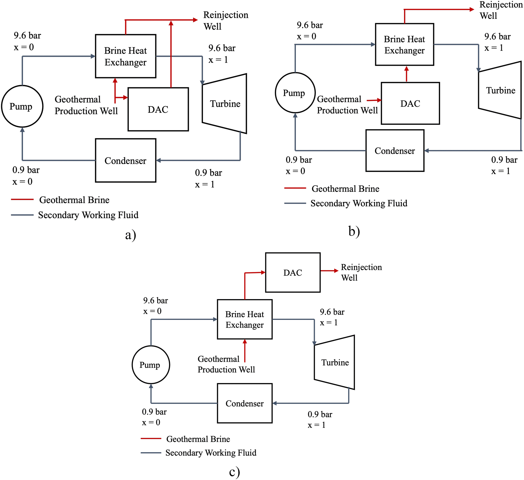 | ||
| Fig. 3 Process flow diagrams illustrating the altered binary geothermal power plant to accommodate DAC in (a) parallel with the ORC, (b) upstream of the ORC, and (c) downstream of the ORC. Note that the variable x is indicative of the working fluid quality where x = 0 indicates a fully liquid state and x = 1 is a fully vapor state. | ||
• DAC in parallel: the DAC regeneration unit is in parallel with the brine heat exchanger (Fig. 3a), investigated for both high-temperature and low-temperature geothermal reservoirs.
• DAC in series – upstream: the DAC regeneration unit is upstream of the brine heat exchanger (Fig. 3b), investigated for the low-temperature geothermal reservoir.
• DAC in series – downstream: the DAC regeneration unit is downstream of the brine heat exchanger (Fig. 3c), investigated for the high-temperature geothermal reservoir.
| Geothermal-DAC configuration | Sensitivity parameter | Geothermal production well temperature [°C] | DAC inlet temperature [°C] | DAC regeneration temperature (DAC outlet) [°C] | Brine reinjection temperature [°C] | Working fluid(s) evaluated |
|---|---|---|---|---|---|---|
| DAC in parallel (low temperature) | Geothermal brine slip stream dedicated to DAC | 86 | 86 | 66 | >65 | Isobutane |
| DAC in parallel (high temperature) | 225 | 225 | 205 | >65 | Isobutane, n-butane, isopentane, n-pentane, cyclopentane | |
| DAC in series – upstream (low temperature) | Temperature drop across the DAC regeneration unit | 86 | 86 | 81–66 | >65 | Isobutane |
| DAC in series – downstream (high temperature) | DAC regeneration temperature | 225 | 100–140 | 80–120 | 80–120 | Isobutane, n-butane, isopentane, n-pentane, cyclopentane |
As in the DAC in parallel case, the DAC regeneration temperature remains to be the lowest temperature across the DAC regeneration unit, which is the exit temperature. In the low-temperature case where the temperature drop is 5 °C, the geothermal brine enters the DAC regeneration unit at 86 °C, the temperature is reduced to 81 °C, then enters the brine heat exchanger in the downstream ORC. This indicates that the DAC regeneration temperature is 81 °C in this case. The DAC in series – upstream configuration was only investigated for the low-temperature geothermal reservoir because this configuration is not slated to be a productive use of the high-enthalpy bring available from the high-temperature reservoir (see Section 2.3.3). The simulations completed and constraints for the DAC in series – upstream case are summarized among the other configurations in Table 3.
2.4. Applying geothermal-DAC methodology to the Raft River combined cycle power plant case study
To apply the same methodology used for a theoretical, new-build binary geothermal power plant integrated with DAC, to one that is already existing, the Raft River combined cycle power plant was used as a case study. The Raft River combined cycle geothermal power plant has been well-documented in publications that explore adding additional turbomachinery to increase its productivity.21 Rather than exploring additional turbomachinery to increase electricity generation, the use of this resource to support geothermal-DAC configurations is explored.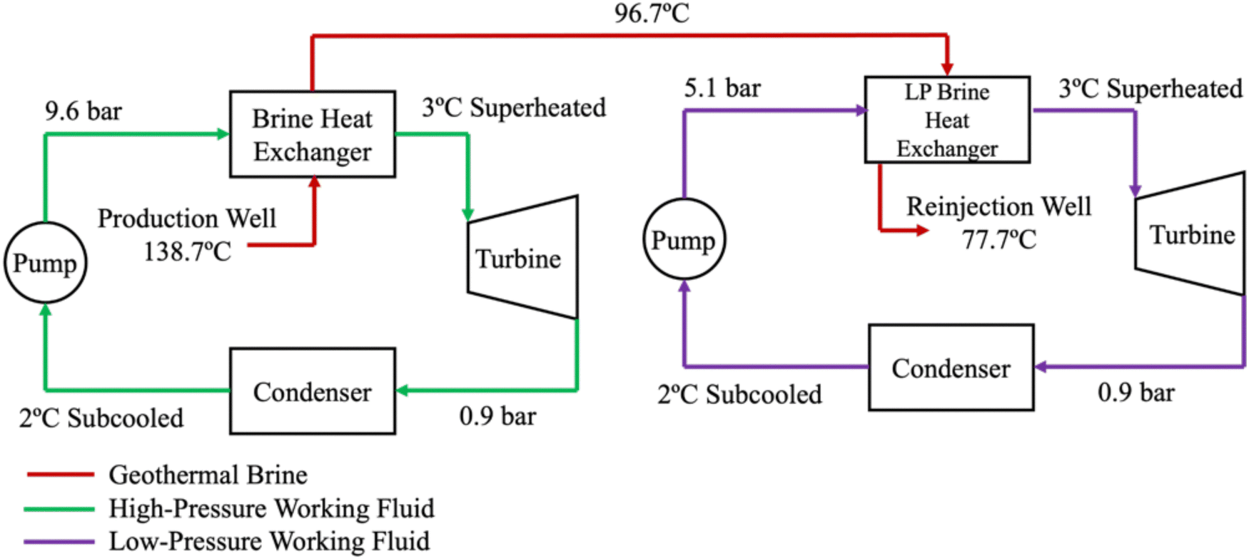 | ||
| Fig. 4 Process flow diagram of a Raft River binary geothermal power plant with both high-pressure (HP) and low-pressure (LP) isopentane organic Rankine cycle (ORC) loops. | ||
| Description | Pressure [bar] | Temperature [°C] | Flow rate, [kg s−1] | Vapor fraction | Phase |
|---|---|---|---|---|---|
| a State points were determined from Aspen Plus once other state points were used as constraints in the initial model. | |||||
| High pressure isopentane ORC | |||||
| Turbine inlet | 9.6 | 113.5 | 139.3 | 1 | Slight superheat |
| Turbine outlet | 0.9 | 62.4 | 139.3 | 1 | High superheat |
| Condensate | 0.9 | 19.9 | 139.3 | 0 | Saturated |
| Low pressure isopentane ORC | |||||
| Turbine inlet | 5.1 | 84.7 | 64a | 1 | Slight superheat |
| Turbine outlet | 0.9 | 48.8 | 64a | 1 | High superheat |
| Condensate | 0.9 | 19.4 | 64a | 0 | Saturated |
| Geothermal brine | |||||
| Production well | 10 | 137.8 | 396.9 | 1 | Liquid with dissolved solids |
| Stream from HP ORC to LP ORC | 10 | 96.7a | 396.9 | 1 | Liquid with dissolved solids |
| Reinjection well | 9.5 | 77.7a | 396.9 | 1 | Liquid with dissolved solids |
Provided that the DAC regeneration unit was positioned in various configurations with the ORC in both the low-temperature and high-temperature cases, it is evident that DAC regeneration can be completed with both high-enthalpy and low-enthalpy geothermal brine. However, it is also evident based on the division of the high-pressure (HP) and low-pressure (LP) ORCs in the Raft River geothermal combined cycle plant, that the HP ORC favors the high-enthalpy geothermal brine, and the LP ORC favors the low-enthalpy geothermal brine. To account for the flexibility of the DAC regeneration unit and the limited flexibility of the high/low pressure ORCs, Fig. 5 illustrates the geothermal-DAC configurations considered for this case study, each of which are based on the previous parallel and series configurations presented above.
 | ||
| Fig. 5 Configurations evaluated throughout the geothermal-DAC integration study. Each can be referred to (a) DAC in parallel with combined cycle power plant, (b) DAC in series – upstream of the LP ORC, and (c) DAC in series – downstream of the HP ORC, each referring to the position of the DAC regeneration system. | ||
(2) DAC in series upstream of LP ORC: the geothermal brine from the production well is first used in DAC regeneration, then used to power the LP ORC.
(3) DAC in series downstream of HP ORC: the geothermal brine from the production well is first used to power the HP ORC, then used in the DAC regeneration step.
2.5. Carbon accounting for geothermal-DAC configurations
To evaluate the different binary geothermal-DAC configurations, metrics to determine the CO2 abatement potential, gross turbine output, and any solar power that would need to be deployed to meet the electricity requirements for DAC were considered. The total CO2 abatement potential of these configurations was determined by aggregating the amount of CO2 that could be reduced by providing geothermal electricity to the grid and the CO2 that could be removed from the DAC process and subtracting the amount of CO2 that was invested in embodied emissions.To determine the total CO2 abatement potential, the total electricity produced, and the total DAC capacity needed to be calculated for each configuration. Solid sorbent DAC requires nearly 2000 kW h per tCO2 with this energy distributed as 80% thermal energy, and 20% electrical energy.3 For this analysis, to account for balance of plant and any unforeseen energy losses, this was inflated by 10%, resulting in 2200 kW h per tCO2 (EDAC,tot). The available thermal energy duty was determined from the DAC unit in the Aspen model, with the modulated sensitivity parameters, and in the following equations will be denoted as EDAC,heat. The electrical requirements for DAC (EDAC,elec) were then calculated using the respective distributions (eqn (1)).
 | (1) |
 | (2) |
| Egrid = (Wturbηdis − Wpump − EDAC,elec)ηyr | (3) |
In the case that the turbine did not produce enough electricity to meet DAC electricity demands, eqn (3) results in a negative number. The absolute value of this result illustrates the required solar capacity to meet the DAC electricity demand (Esolar).
Using the average U.S. grid intensity, 389 kgCO2 per MW h (CIgrid),28 the total CO2 abated via producing geothermal energy for the grid, displacing average grid electricity, was calculated. In cases where the dispatchable grid electricity resulted in a negative number, due to the high electrical demand of DAC, it was assumed that solar energy would be deployed solely to service DAC, so the CO2 abatement via displacing grid electricity (i.e., CO2 reduced) is 0.
For all geothermal power plants, there is a risk of losing working fluid to the environment due to leakage. From a study of 3 operating geothermal power plants in the Great Basin Unified and Imperial County (Western United States), the average leakage when using isobutane working fluid is 0.3 g-Isobutane per kWhe (Lgeo) generated.29 The geothermal power plants studied use various working fluids, but for the embodied CO2 emissions accounting, all scenarios use the same 0.3 g-working fluid per kW he generated leakage rate and a global warming potential (GWP) associated with each working fluid (Table 1). For n-pentane and cyclopentane, where a GWP value was unable to be found in the literature, the GWP of 11 (consistent with isopentane)23 was used. The working fluid leakage and associated GWP was calculated out to CO2eq values using eqn (4).
| EEgeo = (Egrid + EDAC,elec)LgeoGWPwf | (4) |
The embodied emissions for DAC can be estimated based on the size of the DAC plant coupled to the geothermal resource. Terlouw et al. (2021), found that for large-scale (100 ktCO2 per year) solid-sorbent DAC plants, the embodied emissions are nearly 7 kgCO2 per tCO2 captured (EEDAC,unit).30 The embodied emissions for the DAC plant coupled with the geothermal energy resource are calculated using eqn (5).
| EEDAC = NDACEEDAC,unit | (5) |
To date, manufacturing solar PV cells requires mining and high-temperature industrial heating, among other steps that are not fully decarbonized. This results in embodied emissions of 27 kgCO2 per MW h for solar PV arrays (EEsolar,unit).31 When solar PV is needed to meet the electrical demand of DAC, the embodied emissions of the solar panels need to be accounted for by counting against the total CO2 abated value. The embodied emissions of solar PV for each test case was calculated using eqn (6).
| EEsolar = EsolarEEsolar,unit | (6) |
Inclusive in the CO2 abatement potential calculation is the opportunity cost of deploying the geothermal-DAC system, where instead the counterfactual configuration would be a geothermal power plant generating carbon free electricity. In this case, the total CO2 abated is not just the sum of the CO2 reduced from displacing fossil electricity on the grid and the total DAC capacity, but it also accounts for the embodied emissions from the DAC plant, the embodied emissions from any additional solar PV deployment required to meet the electrical demands of DAC, and the opportunity cost of devoting the deployed solar PV to meeting the electrical demands of DAC rather than displacing fossil energy from the grid. Total CO2 abated for any geothermal-DAC test case evaluated in this study are determined by eqn (7).
| Atot,CO2 = NDAC + (EgridCIgrid) − EEgeo − EEDAC − EEsolar − (EsolarCIgrid) | (7) |
2.6. Technoeconomic assessment modeling
A discounted cash flow model was developed to evaluate the levelized cost of energy for the DAC (LCOEDAC) installation by estimating the cash flows for technological constraints and operations when projected out 30 years. The technoeconomic model was solely applied to the energy producing components, namely the binary geothermal power plant and the solar PV installation that may be required in some cases.The capital costs for the ORC were derived from the Aspen Plus model, using the default process economy analyzer. This functionality only accounts for the process equipment, so the other capital expenditures and project financing were estimated by scaling the financial model developed for 50 MW binary geothermal power plants, as documented in the 2020 EIA report.32 In cases where solar energy was needed to meet the electrical needs of DAC, the capital and operating costs for the required systems was scaled relative to the 50 MW solar PV and 150 MW battery facility outlined by EIA in 2020.32 Furthermore, the land area and acreage requirements are calculated based on the estimated land area for a binary geothermal power plant of 0.87 acres per MW14 and for solar PV installations of 31.35 acres per MW.33 The technoeconomic model assumptions used to generate the levelized cost of energy for DAC are illustrated in Table 5.
The levelized cost of energy delivered to DAC was the parameter output from this model because it accounts for the distribution of energy delivered to DAC, in this case 80% thermal energy and 20% electrical energy. Furthermore, the levelized cost of energy (LCOE), which would remain being a distribution of 80% thermal and 20% electrical energy, could be calculated using eqn (8).
 | (8) |
 | (9) |
3. Results & discussion
To determine the impacts of integrating DAC with binary geothermal power plants, key performance parameters were monitored and constrained to ensure operability. The key performance parameters consistent across all configurations were the CO2 reduction potential due to geothermal energy used to generate grid electricity, CO2 removal potential due to the DAC facility capacity, and the total CO2 abatement potential, which is a sum of CO2 reduction potential and CO2 removal potential, after accounting for embodied and opportunity cost CO2 emissions. When there is not enough geothermal energy to provide both thermal and electrical requirements for DAC, the solar energy required to meet these needs is also quantified. Furthermore, the reinjection well temperature was monitored to determine each configuration's ability to utilize the maximum enthalpy available from each reservoir. The maximum enthalpy available is associated with the difference between the reservoir, or production well temperature, and the minimum reinjection well temperature, 65 °C. Lastly, each test case was evaluated using the technoeconomic model, in which the key performance parameters for the levelized cost of energy delivered to the DAC system (LCOEDAC), and the levelized cost of grid electricity generation (LCOEGrid) were projected.In general, each of the investigated configurations to integrate geothermal energy and DAC, resulted in one of the following geothermal-DAC plants:
• Geothermal plant for DAC and producing grid electricity: in cases where the geothermal energy plant generates more electricity than that needed by the DAC plant, excess dispatchable geothermal electricity can be generated for the grid. This is indicated by a positive value for geothermal electricity generated for the grid, and a zero value for required solar PV.
• Stand-alone geothermal-DAC plant: in cases where the geothermal energy is distributed such that it can provide both thermal energy and electricity to DAC, but there is negligible excess electricity for the grid. This is indicated by a zero or slightly positive value for geothermal electricity generated for the grid, and a zero value for the required solar PV.
• Geothermal-DAC plant with solar PV for makeup electricity: in cases where the geothermal energy is unable to provide both the thermal and electrical requirements for DAC, and solar PV must be deployed to supplement the electricity needs. This is indicated by a zero value for the geothermal electricity generated for the grid, and a positive value for the required solar PV.
3.1. Geothermal-DAC configurations with low-temperature geothermal reservoir
To determine the opportunities that exist for integrating low-temperature geothermal reservoirs with DAC, a resource assumed to be 86 °C was evaluated. The applicable configurations for the low-temperature geothermal reservoir are the DAC in parallel and DAC in series – upstream cases (Fig. 6). The DAC in series – downstream case is not applicable because the ORC utilizes a large amount of enthalpy, and there is not enough left to run a DAC facility. Furthermore, the only working fluid that could be used in a geothermal-DAC configuration in the low-temperature reservoir case was isobutane.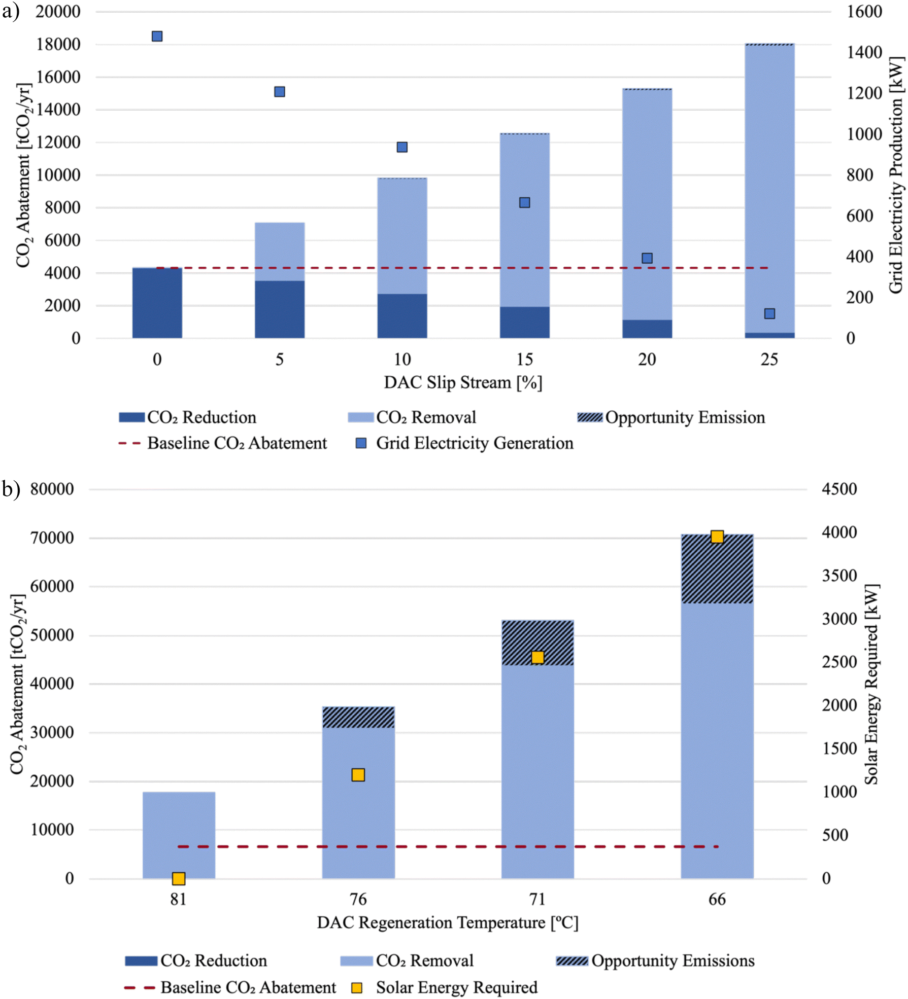 | ||
| Fig. 6 Geothermal-DAC opportunities for a low-temperature, 86 °C, geothermal reservoir with (a) DAC in parallel, and (b) DAC in series – upstream configurations, with dark blue bars indicating the CO2 reductions from geothermal electricity generation for the grid, the light blue bars indicating CO2 removal from the DAC facility, the hashed bars indicating the embodied and opportunity cost emissions associated with the test case installation, red dashed line indicating the baseline CO2 abatement achieved with the baseline binary geothermal power plant, blue square markers indicating the geothermal electricity generated for the grid, and yellow square markers representing the solar PV that is needed to meet the full energy requirements of the DAC facility. | ||
The results for the DAC in parallel configuration are shown in Fig. 6a. The left-most data point shows the total CO2 abatement potential and grid electricity available in the binary geothermal power plant baseline condition, where the DAC slip stream is equal to 0%. This results in 1.48 MW of geothermal electricity being provided to the grid, which has an associated CO2 reduction of 4314 tCO2 per year, based on its ability to replace average grid electricity generation. The red dashed line, indicating the baseline CO2 abatement is set to that level for ease of comparison across the other test cases. These results also show that as the geothermal brine slip stream dedicated to DAC increases, the total CO2 abatement potential increases, and the grid electricity production decreases. The rise in CO2 abatement potential is due to the geothermal brine being able to meet the thermal energy requirements of the DAC facility, and the electricity generation being devoted to meeting the electricity requirements. However, as more brine is dedicated to the DAC slip stream, there is less available to generate electricity, and the DAC facility then also requires more of the electricity that is generated. Provided this feedback, the maximum sustainable DAC slip stream that can be achieved in this configuration is 25%, resulting in a standalone geothermal-DAC plant. In this case, the CO2 abatement potential is maximized, reaching 21075 tCO2 per year, an improvement of 388% above the baseline case.
Fig. 6b shows the results from the same low-temperature geothermal reservoir being used to power the DAC in series – upstream configuration. In this case, the baseline CO2 abatement potential condition is set to the same value as in the DAC in parallel case because it represents the binary geothermal power plant that is not equipped with DAC at all and is represented by the red dashed line. Upon initial inspection, it is evident that the geothermal reservoir can only sustain the DAC in series – upstream configuration without requiring solar PV deployment for the first test case, where the DAC regeneration temperature is 81 °C, associated with a temperature drop across the DAC regeneration unit of 5 °C. However, with a temperature drop of 10 °C across the DAC regeneration unit, the exiting geothermal brine is then only 76 °C, which is too low for it to be used in the ORC productively, therefore, requiring solar PV to meet the electrical needs of the DAC facility. This then simplifies the DAC in series – upstream configuration, such that the geothermal brine is solely meeting the thermal energy requirements for the DAC facility, and the solar PV being deployed to meet the electrical requirements. Furthermore, it is shown that the DAC regeneration temperature drops below the lower bound that is usually associated with solid sorbent regeneration (approximately 80 °C), illustrating that this reservoir would have the best DAC capacity opportunities when coupled with DAC sorbents that have lower regeneration temperatures than most sorbents used today, which is an active area of research in the DAC community. Despite the caveats that may be associated with the cases where the temperature drop across the DAC regeneration unit leads to lower regeneration temperatures, it should be noted that when the DAC regeneration temperature is 81 °C, the total CO2 abatement potential that can be achieved is 17616 tCO2 per year, which is an improvement of 308% over the baseline condition.
To best understand the costs to the DAC system of sourcing the energy from a low-temperature geothermal reservoir as opposed to other sources, a technoeconomic study was performed for each test case in both the DAC in parallel and DAC in series – upstream configurations. Fig. 7 shows how the levelized cost of energy delivered to the DAC (LCOEDAC) system and the levelized cost of grid electricity generation (LCOEGrid) change as the slip stream for DAC changes in the DAC in parallel configuration. These can both be compared to the levelized cost of electricity from the binary geothermal power plant described in the 2020 EIA report (LCOEGrid Baseline, $0.015 per kW h).32 It is evident that as the DAC slip stream increases, and the DAC facility capacity also increases, the LCOEDAC decreases. In the case with the DAC slip stream is equal to 5%, the LCOEDAC shown in Fig. 7 is $8579 per tCO2, or $3.90 per kW h. This then decreases to $1999 per tCO2 or $0.91 per kW h when the slip stream is 25%.
 | ||
| Fig. 7 Levelized cost of energy for DAC operations and levelized cost of grid electricity generation when DAC is coupled to a low-temperature geothermal reservoir with varied slip streams. | ||
The trend for LCOEDAC mirrors the impact that the increasing DAC slip stream has on the LCOEGrid, whereas the slip stream increases, this cost continues to increase. This is in-part due to DAC making more efficient use of the thermal energy from the reservoir, in comparison to converting it to electricity, and due to the lessened amount of dispatchable electricity due to the increased DAC operations. It should also be noted that in this configuration, the minimum value for LCOEGrid ($0.22 per kW h) remains above the LCOEGrid Baseline ($0.015 per kW h), which is likely due to the low-temperature of the reservoir, and therefore the overall smaller capacity of the binary geothermal power plant (1.48 MW in the baseline scenario vs. 50 MW from the EIA report32). This then indicates that DAC companies could prioritize purchasing electricity from other sources that can provide it at a lower cost than that of this scenario, but the efficiency of converting that electricity to heat to meet the thermal demands of DAC would also need to be weighed.
The technoeconomic data for the DAC in series – upstream configuration using the low-temperature reservoir is a bit nuanced due to the differences in how the system operates. Fig. 8 illustrates the technoeconomic performance of this geothermal-DAC configuration, highlighting the levelized cost of energy delivered to DAC (LCOEDAC) and the levelized cost of grid electricity generation for the 50 MW binary geothermal plant detailed in the 2020 EIA report32 (LCOEGrid Baseline). In this configuration, there is no test case that results in grid electricity generation, so the levelized cost of grid electricity generation is not included, as it would be infinite. However, the LCOEDAC shows an interesting trend where it begins near $2000 per tCO2 ($0.91 per kW h) when the regeneration temperature is 81 °C, then increases as the regeneration temperature decreases, then starts on a decreasing trend at 76 °C, eventually reaching $401 per tCO2 ($0.19 per kW h) when the regeneration is 66 °C. This peak at 76 °C illustrates the transition from the test case where solar energy is not needed to support this configuration to the test cases where solar energy is then required to sustain this configuration. These test cases are when the regeneration temperature is 76 °C, 71 °C, and 66 °C. As the solar installation increases in size, the economics scale, such that the decrease in LCOEDAC as the regeneration decreases is due to the scaling down of the geothermal system and economies of scale achieved by the solar and battery system.
 | ||
| Fig. 8 Levelized cost of energy for DAC delivered by the DAC in series – upstream configuration using a low-temperature geothermal reservoir, compared to the baseline levelized cost of the grid electricity generation baseline case. | ||
It is evident that low-temperature geothermal reservoirs such as this are uneconomic for grid electricity generation, with LCOEGrid values well above the LCOEGrid Baseline metrics reported on by EIA.32 However, it is interesting to note the improved CO2 abatement potential of coupling low-temperature geothermal reservoirs with DAC because there may be ways to pursue these installations coupled to specific scenarios that would reduce costs. One of these scenarios may be leveraging abandoned, retired, or orphan wells, in which case the drilling costs of the project, which make up 24% of the capital costs for the geothermal system, may be reduced. Furthermore, this could present an opportunity to valorize otherwise abandoned assets, while also remediating sites that currently host these wells. In the United States alone, there are 3.7 million abandoned or orphaned oil and gas wells, which may present potential for geothermal-DAC deployments.35
3.2. Geothermal-DAC configurations with a high-temperature geothermal reservoir
On the other end of the binary geothermal power plant spectrum, is the high-temperature reservoirs, which often have much more opportunity and flexibility for brine usage. However, only the DAC in parallel and DAC in series – downstream configurations were evaluated to quantify these opportunities. The DAC in series – upstream configuration would not have been competitive with these provided similar heat duty would be dedicated to DAC, and less electricity would be able to be generated from the ORC due to the lower enthalpy brine. To quantify the opportunities for DAC in parallel and DAC in series – downstream configurations, while considering the best practices seen throughout the geothermal industry, each configuration was evaluated using all applicable secondary working fluids for the ORC. Provided the differing thermodynamic properties for each of the working fluids, the baseline binary geothermal power plant electricity generation, and therefore the CO2 abatement potential, differs for each. The differences between the baseline power plant conditions for each working fluid are summarized in Table 6.| Working fluid | Electricity generation [MWe] | Working fluid flow rate [kg s−1] | Baseline CO2 abatement [tCO2 per year] |
|---|---|---|---|
| Isobutane | 13.5 | 363 | 39.3 |
| n-Butane | 16.0 | 318 | 46.7 |
| Isopentane | 19.0 | 299 | 55.5 |
| n-Pentane | 18.8 | 288 | 54.9 |
| Cyclopentane | 20.0 | 286 | 58.2 |
The results of DAC in parallel configuration deployed with the high-temperature geothermal reservoir are shown in Fig. 9. When DAC is positioned in parallel with the ORC, the slip stream of brine that is dedicated to DAC regeneration can be increased to 70% for all working fluids except isobutane, which can only sustain a DAC slip stream up to 65%, before the electricity generated is this configuration is negligible. Similar to the 86 °C reservoir case, as the DAC slip stream increases, the total electricity produced for the grid, and the associated CO2 reductions, decreases. However, the CO2 removed and the overall CO2 abatement potential increases (Fig. 9a).
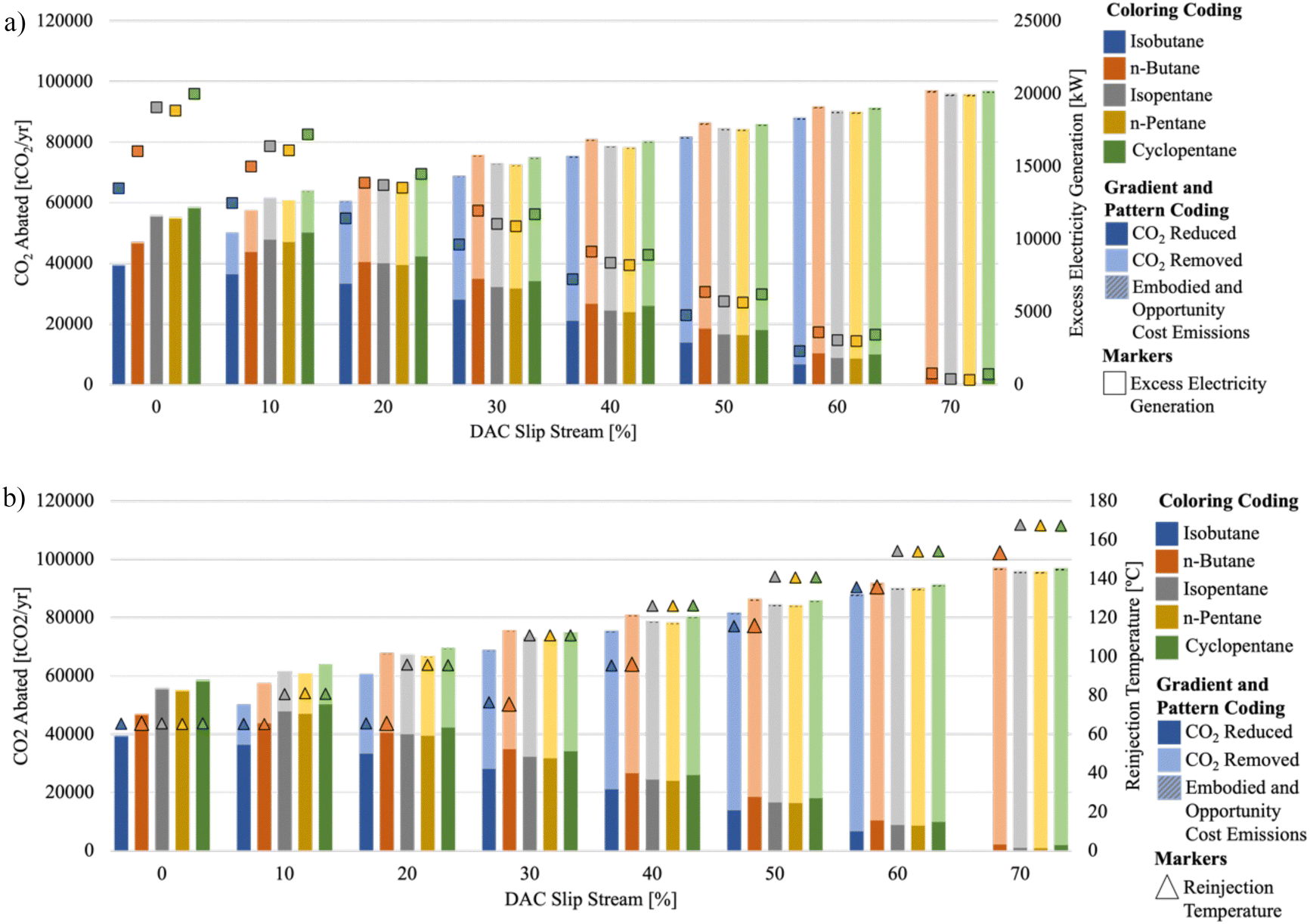 | ||
| Fig. 9 CO2 abated in the DAC in parallel configuration for a geothermal reservoir temperature of 225 °C, showing (a) grid electricity generation, and (b) reinjection well temperature, using a variety of working fluids: isobutane (blue gradient), n-butane (orange gradient), isopentane (gray gradient), n-pentane (yellow gradient), and cyclopentane (green gradient). | ||
A close inspection of the power produced when using the different working fluids in this configuration illustrates that isopentane and cyclopentane result in the highest electricity generation of all the working fluids. This is expected due to the pressure constraints on isobutane and n-butane, as well as the thermodynamic properties of n-pentane. This trend is present because at temperatures above approximately 210 °C, isopentane and cyclopentane have larger vapor fractions than that of n-pentane, resulting in more electricity generation (see Fig. S3 in the ESI†).
Furthermore, Fig. 9b shows that as the slip stream for DAC increases, the reinjection temperature also increases. This consistent increase in reinjection temperature is attributed to the higher temperature of the geothermal brine exiting the DAC regeneration unit, compared to that exiting the brine heat exchanger, leading to an increase in temperature at the reinjection well. Provided that the reinjection temperature could be lower, and more enthalpy is extracted from the geothermal reservoir, this does not necessarily indicate the most efficient use of the thermal energy available. Rather, this illustrates an opportunity where a geothermal-DAC configuration may benefit from a bottoming cycle (low-pressure ORC) to make use of the enthalpy that could still be harnessed prior to reinjection.
The CO2 abatement potential is the greatest when the DAC slip stream is the greatest, at 65% for isobutane, and 70% for the other working fluids. For the different working fluids used in this study, the maximum CO2 abatement potentials for each in the DAC in parallel configuration are 94.0 ktCO2 per year for isobutane, 96.2 ktCO2 per year for n-butane, 95.1 ktCO2 per year for isopentane, 95.0 ktCO2 per year for n-pentane, and 96.1 ktCO2 per year for cyclopentane. A comparison between the test cases resulting in the maximum CO2 abatement potential for each of different working fluids and how these compare to the baseline conditions is shown in Table 7. More detailed data for each intermediate case is shown in Section S4 of the ESI.†
| Working fluid | DAC in parallel | DAC in series – downstream | ||||
|---|---|---|---|---|---|---|
| CO2 abatement potential | Improvement compared to baseline conditions (%) | LCOEDAC | CO2 abatement potential | Improvement compared to baseline conditions (%) | LCOEDAC | |
| (ktCO2 per year) | $ per tCO2 | (ktCO2 per year) | $ per tCO2 | |||
| Isobutane | 90.4 | 130 | $140 | 90.7 | 132 | $127 |
| n-Butane | 96.2 | 106 | $128 | 88.0 | 89 | $129 |
| Isopentane | 95.1 | 71 | $134 | 104.0 | 88 | $104 |
| n-Pentane | 95.0 | 73 | $135 | 103.3 | 89 | $104 |
| Cyclopentane | 96.1 | 65 | $130 | 106.1 | 83 | $101 |
A technoeconomic assessment was performed for each test case to better illustrate the costs of deploying a DAC in parallel system coupled to a high-temperature geothermal reservoir, and to better quantify the performance of each of the working fluids in this configuration. The results, illustrating the levelized cost of energy delivered to DAC (LCOEDAC), the levelized cost of grid electricity generation (LCOEGrid), and the LCOEGrid baseline as per the 2020 EIA report,32 are shown in Fig. 10. When the slip stream for DAC is 0, and the geothermal power plant is just producing grid electricity, the LCOEGrid is cost competitive with the LCOEGrid baseline for all working fluids evaluated. The range of LCOEGrid in this condition ranges from $0.0084–0.012 per kW h, whereas the LCOEGrid baseline value is $0.015 per kW h. As the DAC slip stream increases, the LCOEGrid also increases, linearly, until the DAC slip stream reaches approximately 40%, where it takes an exponentially increasing trend.
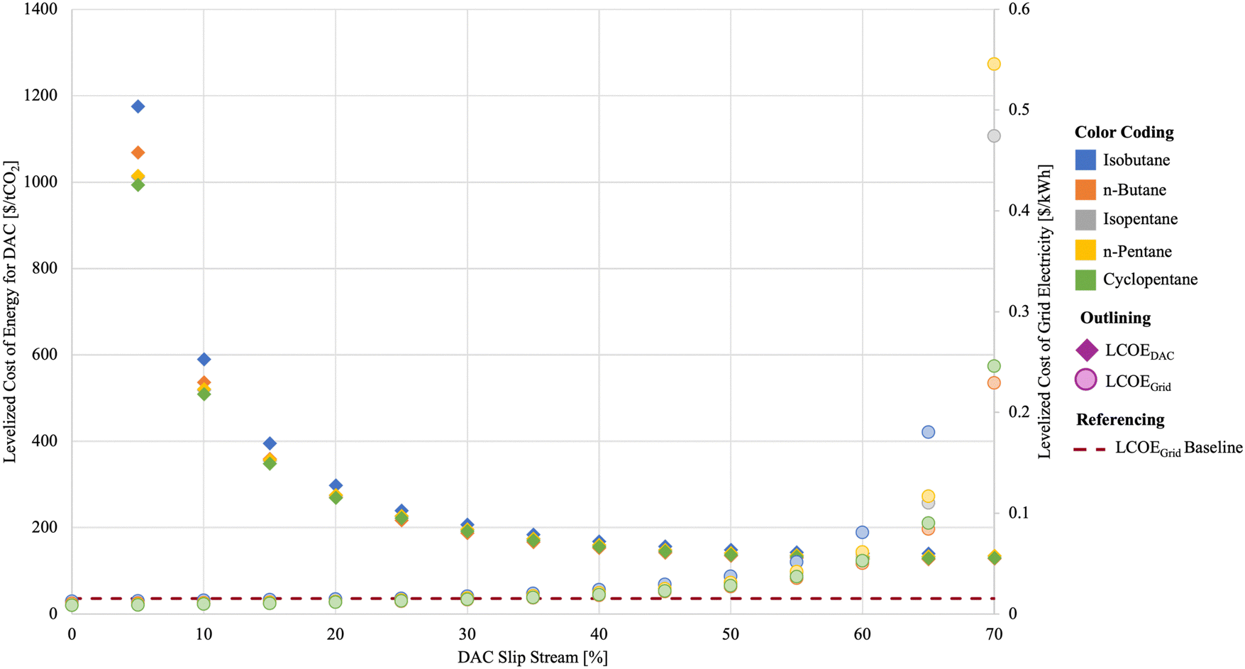 | ||
| Fig. 10 Technoeconomic results for DAC in parallel configuration using a high-temperature geothermal reservoir, illustrating the levelized cost of energy delivered to DAC (LCOEDAC), levelized cost of grid electricity generation (LCOEGrid), and the LCOEGrid baseline value, for all working fluids evaluated. | ||
The LCOEDAC shows the opposite trend, where it first starts high then exponentially decreases as the DAC slip stream increases. This is due to the increased heat duty that results from a larger DAC slip stream, indicating that the DAC facility can be sized to remove more CO2 from the atmosphere, and additionally, some of the geothermal power plant equipment would be resized for optimal operation, often scaling down. As the DAC slip stream increases to its maximum for each of the working fluids, the LCOEDAC hovers between $128 and 140 per tCO2 ($0.058–0.064 per kW h).
The other configuration evaluated with the high-temperature geothermal reservoir is the DAC in series – downstream configuration, where the highest enthalpy brine is first used in the brine heat exchanger to vaporize the working fluid, then the cooled brine is used to drive the DAC regeneration step. The DAC regeneration step in these test cases is modeled with a 20 °C temperature drop, and the lowest temperature across the DAC regeneration unit is the regeneration temperature. Also, because the DAC regeneration unit is the farthest downstream unit operation, the regeneration temperature is synonymous with the reinjection well temperature.
The results from the DAC in series – downstream configuration are shown in Fig. 11. The results from the test cases considering DAC regeneration temperatures ranging from 80–120 °C are shown, illustrating the CO2 reduced from the grid electricity generation, CO2 removal from the DAC facility, embodied and opportunity cost emissions, and the value of grid electricity generation. It can be seen that as the DAC regeneration temperature increases, the grid electricity generation for each test case decreases. This is consistent with all working fluids considered in this analysis. The electricity generation decreases because as the DAC regeneration temperature increases, the temperature of the brine entering the DAC regeneration unit also increases, therefore, decreasing the thermal energy available to the brine heat exchanger that drives the ORC. The decreased thermal energy results in decreased electricity generation, and of that electricity generation, a portion of it is still required to meet the electrical requirements of the DAC plant.
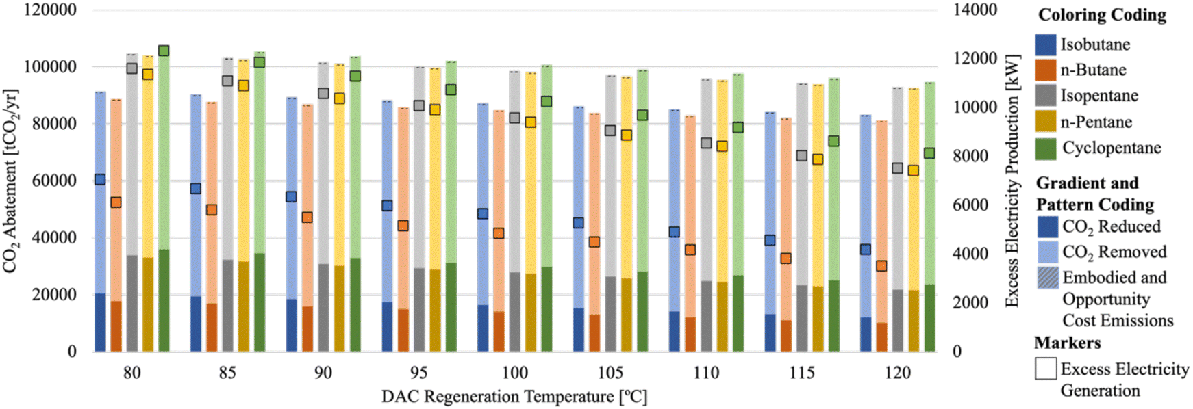 | ||
| Fig. 11 CO2 abated for the DAC in series – downstream configuration for a geothermal reservoir temperature of 225 °C, showing grid electricity generation using a variety of working fluids: isobutane (blue gradient), n-butane (orange gradient), isopentane (gray gradient), n-pentane (yellow gradient), and cyclopentane (green gradient). | ||
The reinjection well temperature increases as the DAC regeneration temperature increases because these temperatures are the same. Provided that DAC is the farthest downstream unit operation, and the DAC regeneration temperature is assumed to be the lowest temperature across the DAC regeneration unit, the brine that exits the DAC regeneration unit is then pumped back down into the reinjection well. Due to the reinjection temperature being well above the baseline of 65 °C, especially when the DAC regeneration temperature is closer to 120 °C, the DAC in series – downstream configuration may also benefit from a bottoming cycle to harness enthalpy that would otherwise go unutilized.
Overall, integrating DAC with a geothermal power plant in the DAC in series – downstream configuration increases the CO2 abatement potential that can be achieved with the geothermal resource. The best performing results from the DAC in series – downstream configuration are tabulated and compared with those from other configurations in Table 7. The total improvement over the baseline condition of the geothermal power plant being used solely for electricity generation is 62–132%, depending on the working fluid used, and all associated with the test case where the DAC regeneration temperature is the lowest at 80 °C. A more detailed table, with all the reported data for each test case can be found in Tables S1 and S2 in the ESI.†
The DAC in series – downstream configuration for the high-temperature geothermal reservoir test cases presents interesting insights when the technoeconomics are assessed. The technoeconomic results for each of these test cases are shown in Fig. 12. Both the levelized cost of energy delivered to DAC (LCOEDAC) and levelized cost of grid electricity generation (LCOEGrid) increase with increasing DAC regeneration temperature conditions. This indicates that the lowest cost system is one in which the DAC sorbents regenerate at lower temperatures, coinciding with the scenario that illustrates the greatest potential for increased CO2 abatement. Most of the other configurations struggled to be cost competitive with the baseline grid generated electricity (LCOEGrid baseline), but in this configuration, using either n-pentane or cyclopentane, and low-regeneration temperature sorbents for DAC, the DAC in series – downstream condition can achieve an LCOEGrid of $0.014–0.015 per kW h, and a LCOEDAC of $101–104 per tCO2 (0.046–0.047 per kW h).
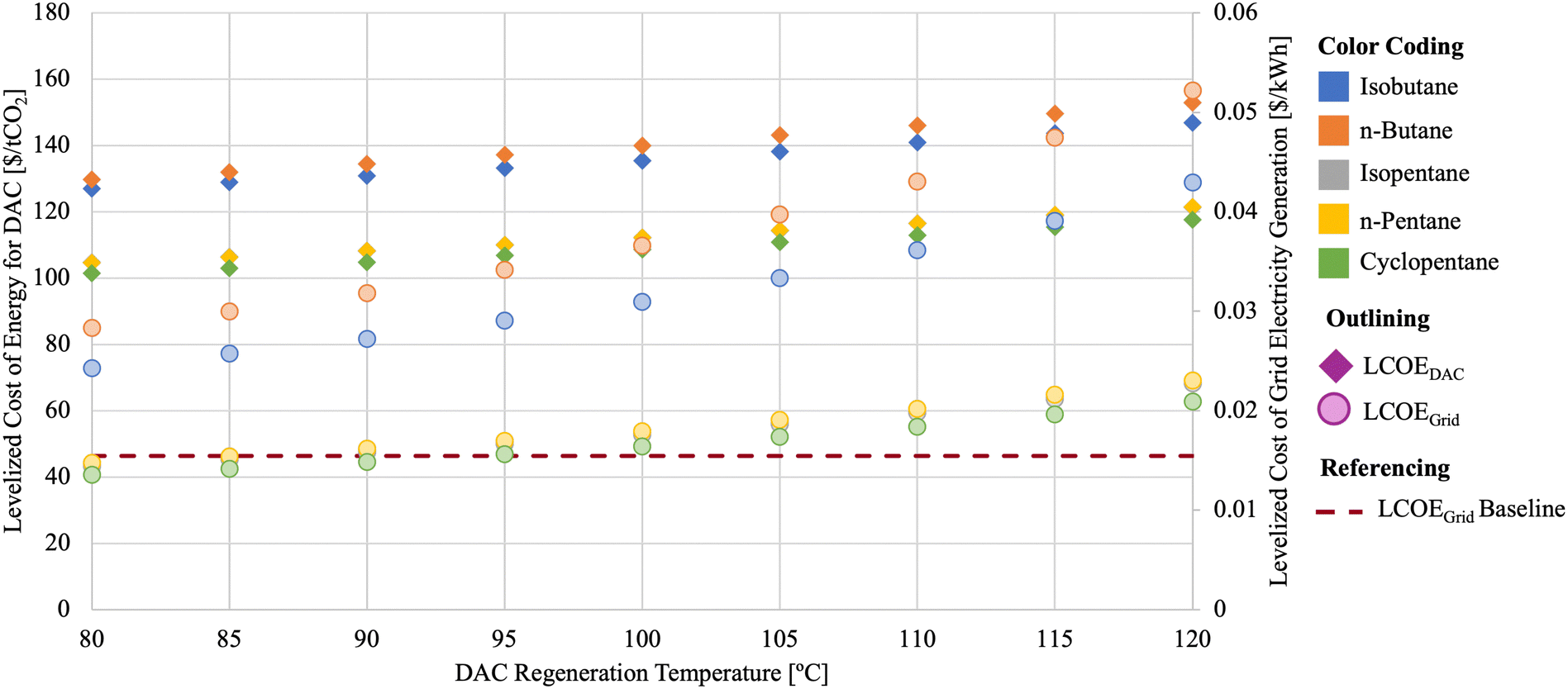 | ||
| Fig. 12 Technoeconomic results from evaluating DAC in series – downstream with a high-temperature geothermal reservoir, illustrating the levelized cost of energy delivered to the DAC system (LCOEDAC) and levelized cost of grid electricity generation (LCOEGrid), compared to the levelized cost of grid electricity from the binary geothermal power plant baseline (LCOEGrid baseline). | ||
Overall, integrating DAC with a geothermal power plant in any of the investigated configurations leads to higher potentials for CO2 abatement than if the geothermal energy was to be used solely to generate electricity. This integration can come at a cost where the LCOEDAC is increased from that of other sources depending on the geothermal resource and the configuration of the DAC integration. The LCOEDAC results presented here range from $101 per tCO2 when considering the DAC in series – downstream configuration using the high-temperature geothermal reservoir to $8580 per tCO2 when considering the DAC in parallel case with a slip stream of 5% using the low-temperature geothermal reservoir. One clear benefit of the geothermal-DAC integration, specifically with configurations that do not require solar PV deployment, is that both the thermal and electrical needs of DAC can be consistently met from a single continuous resource. However, even in cases where solar PV deployment is needed, specifically with lower temperature geothermal reservoirs, it has been shown that they may be positioned to meet the thermal energy requirements of DAC facilities, positioning them to be valorized for applications other than electricity generation. This is particularly interesting when considering abandoned, retired, or orphaned wells that could be repurposed for harnessing geothermal energy. It should also be noted, that to meet the thermal energy requirements of DAC, the geothermal reservoirs can be lower in temperature than those typically considered for electricity generation purposes, providing opportunities for otherwise uneconomic geothermal energy resources to be harnessed for climate change mitigation technologies.
3.3. Geothermal-DAC configurations using the Raft River power plant case study
To illustrate how the geothermal-DAC configurations developed in the previous sections can be applied to an existing geothermal power plant, a similar analysis was performed using the Raft River power plant as a case study, with a focus on the CO2 abatement potential. The following sections illustrate the results of integrating DAC with the Raft River binary geothermal power plant, utilizing the working fluid that is already used onsite, isopentane. The technoeconomics of this case study were not investigated because it is inconclusive which existing infrastructure could be leveraged in transitioning or retrofitting the Raft River plant with DAC. However, for any actively producing binary geothermal power plant, integration with DAC should be considered, especially if the geothermal reservoir shows signs of cooling over time, reducing its ability to generate grid electricity.3.4. DAC in parallel with a combined cycle geothermal power plant
The DAC in parallel test case is configured such that the DAC regeneration unit is in parallel with the HP ORC, and the LP ORC is left downstream of both the DAC regeneration unit and the HP ORC. In initial investigations, it became clear that as the DAC slip stream increased from 0–10%, the temperature of the brine that connects both HP ORC and LP ORC began to decline, so much so, that it reduced the turbine capacity of the LP ORC (Fig. S5 in the ESI†). This occurs because the enthalpy from the production well is finite, and the high-enthalpy brine is being used by both the HP ORC and the DAC unit when in the DAC in parallel configuration. This lessens the enthalpy available for the LP ORC. Coupled with the constraints on the reinjection temperature, this decreases the heat extraction that can be completed to generate electricity in the LP ORC, resulting in a decreased electricity output (Fig. S5 in the ESI†).A quasi-static constraint can be utilized to ensure there is sufficient enthalpy available for use in the LP ORC to justify the capital investment in this configuration. This constraint, similar to the one used for the reinjection temperature, ensures the working fluid stream connecting the two ORCs remains above or no more than 0.5 °C below that of the baseline temperature (96.69 °C), when the DAC regeneration step is not present (Fig. 4). In the DAC in parallel with the combined cycle geothermal power plant configuration (Fig. 5a), when both temperature constraints (on the stream connecting HP and LP ORCs, and reinjection well temperature) are enacted it is possible to dedicate 75% of the geothermal brine from the production well to the DAC regeneration unit and still generate enough electricity to meet the demand of DAC and provide some to the grid from both the HP and LP turbines (Fig. 13).
 | ||
| Fig. 13 CO2 abatement potential from coupling the Raft River geothermal energy power plant with DAC in parallel with the HP ORC, while constraining the working fluid temperature in the stream connecting the HP ORC and LP ORC, and the reinjection temperature. CO2 abatement is determined as the sum of CO2 displaced from fossil electricity generation (gray bars) and the CO2 removed by DAC (solid blue bars), after accounting for working fluid, embodied, and opportunity cost emissions (hashed blue bars). | ||
To illustrate the trend between grid electricity generation and overall CO2 abatement potential between the two ends of this spectrum, in the baseline condition, when the DAC slip stream is 0%, the total grid electricity generated is 11.4 MW, which corresponds to 33100 tCO2 per year being reduced by displacing fossil electricity. At the point where 75% of the geothermal brine is being dedicated to the DAC regeneration unit in parallel with the HP ORC, the total grid electricity generated is reduced to 0.6 MW, corresponding to 1850 tCO2 per year being reduced, while the total DAC capacity reaches nearly 120000 tCO2 per year. Combining both of these metrics results in a total CO2 abatement potential of nearly 122 ktCO2 per year. This is an improvement of approximately 270% over the baseline CO2 abatement of 33.1 ktCO2 per year when the geothermal power plant was solely producing electricity.
An interesting artifact that arises due to the difference in temperature regime utilized by both the high-pressure brine heat exchanger in the HP ORC and the DAC regeneration unit, which can be seen in the LP turbine capacity once the DAC slip stream reaches above 40%. The quasi-static temperature constraint results in the LP turbine power output hovering around 3.5 MW, but it steadily increases to 5.7 MW by the time the DAC slip stream increases to 75%. This can be explained by the difference in brine exit temperature from the HP brine heat exchanger and the DAC regeneration unit. In the HP brine heat exchanger, the working fluid, isopentane, is vaporized, and to reduce the likelihood of scaling, the geothermal brine exit temperature can reach no lower than 65 °C. However, in the DAC regeneration unit, the temperature drop of the geothermal brine is only as great as 20 °C. This illustrates that brine leaving the brine heat exchanger can be as low as 65 °C and that leaving the DAC regeneration unit can be as high as 117.8 °C. As the slip stream through the DAC regeneration unit increases, the portion of brine at 117.8 °C increases, ultimately raising the temperature of the brine stream that connects the HP ORC and LP ORC, resulting in more enthalpy for the LP ORC to convert to electricity.
At a time when the decarbonization of the grid is top of the mind to reach net-zero goals, there is a distinct focus on using renewable energy for grid decarbonization first and foremost, however it is promising to recognize that there are geothermal-DAC configurations, specifically highlighted in the DAC in parallel category, that can dispatch excess electricity to the grid while also contributing to carbon removal activities. This electricity could be dispatched to support local communities or distributed grids, in addition to supporting DAC operations. For example, a mid-range slip stream value that may be beneficial to optimize further when considering a geothermal resource, like that at the Raft River plant, may be the 30% DAC slip stream case, which is estimated to produce enough electricity to power nearly 5800 American households annually, while supporting an approximately 48000 tCO2 per year DAC facility.36
3.5. DAC in series – upstream of LP ORC
When DAC is upstream of the brine heat exchanger that drives the ORC, it benefits from the higher enthalpy brine, meaning the enthalpy left for the downstream ORC is a function of the heat loss in the DAC regeneration unit, and therefore, the DAC regeneration temperature. Provided that the LP ORC is already optimized for utilizing low enthalpy brine, it was decided that for the DAC in series – upstream configuration, the LP ORC would be utilized in the downstream position.For each test case with DAC in series – upstream (Fig. 5b) the CO2 reductions, CO2 removals, turbine power, and required solar PV are shown in (a). In the test cases for DAC in series – upstream of the LP ORC, the DAC regeneration temperature range spans from 132.8 °C (5 °C below production well temperature) to the maximum, 117.8 °C (20 °C below the production well temperature). As the DAC regeneration temperature decreases (associated with increased heat loss to the DAC regeneration unit), the CO2 reductions for each decrease, as does the turbine power. This is due to the increasing electrical demand from DAC, coupled with the decreased enthalpy available to the LP ORC to generate electricity. When the DAC regeneration temperature reaches 122.8 °C (15 °C below the production well temperature), negligible CO2 reductions are achieved, illustrating negligible geothermal electricity is generated for the grid, so the electricity that is generated, is just enough to meet the electrical demands of DAC. This is an example of a standalone geothermal-DAC plant, where no additional electricity is needed to meet the energy requirements of DAC, but there is also no excess of generated electricity. As the DAC regeneration temperature continues to decrease to 117.8 °C (associated with more heat loss to the DAC regeneration unit), 2.8 MW of solar PV is needed to meet the electrical demand for DAC because the LP ORC is unable to generate enough electricity to sustain the DAC plant on its own.
The enthalpy that is utilized in each of the DAC in series – upstream of the LP ORC test cases, is similar to that of the baseline geothermal power plant. This is illustrated by tracking the reinjection well temperature, as a proxy for the total enthalpy use of the system. The reinjection well temperature for all test cases hovers around the baseline reinjection well temperature, 77.7 °C, indicating that the efficiency of enthalpy usage in this configuration is similar to that of the baseline geothermal power plant.
The main advantages that can be seen from the DAC in series – upstream of the LP ORC configuration can be summarized by comparing the CO2 abatement potential for each of the test cases. When the DAC regeneration temperature is 132.8 °C (5 °C below the production well temperature), the total CO2 abatement potential is estimated to be 57.3 ktCO2 per year, an improvement of 73% above the baseline condition where the geothermal power plant is solely generated grid electricity. As the DAC regeneration temperature decreases to 122.8 °C, the total CO2 abatement potential increases to 119.6 ktCO2 per year, an improvement of 261% over the baseline condition. In the condition that requires solar PV deployment and a DAC regeneration temperature of 117.8 °C (20 °C below the production well temperature), the total CO2 abatement potential is 149.9 ktCO2 per year, an improvement of 352% above the baseline condition. This illustrates that the increased CO2 abatement potential in this test case is larger than the sustained embodied and opportunity cost emissions of needing to deploy 2.8 MW of solar capacity to meet the electrical demand of the associated DAC facility (Fig. 14).
 | ||
| Fig. 14 CO2 abatement potential for DAC in series – upstream of the LP ORC configuration, exhibiting the turbine power and solar deployment required to meet the DAC electricity needs in each test case. Various regeneration temperatures were tested, all within 20 °C of the production well temperature. | ||
3.6. DAC in series – downstream of the HP ORC
When DAC is positioned downstream of the brine heat exchanger that drives the ORC (Fig. 5c), it ensures that the ORC can make use of the highest enthalpy available. The DAC in series – downstream of the HP ORC, then allows for the HP ORC to access this high enthalpy geothermal brine, which is what it was designed to utilize. The results from the various test cases in this configuration are presented in Fig. 15. When the DAC regeneration temperature is 80 °C, it is possible to achieve a standalone geothermal-DAC plant (no additional solar PV required and no or little electricity generation to the grid). As the DAC regeneration temperature increases, the temperature of the brine entering the DAC regeneration unit also increases. This then results in less enthalpy being available to run the ORC so, the turbine power decreases, the need to deploy solar PV increases, and by virtue, the opportunity cost emissions increase. Furthermore, the DAC regeneration temperature is synonymous with the reinjection well temperature because the DAC regeneration unit is the farthest downstream unit operation. This means that as the DAC regeneration temperature increases, the reinjection well temperature also increases, illustrating a less efficient use of the total enthalpy available from the geothermal reservoir. | ||
| Fig. 15 CO2 abatement potential for DAC in series – downstream of the HP ORC configuration. Note the reinjection temperature is synonymous with the DAC regeneration temperature in this configuration. | ||
All the test cases evaluated with the DAC in series – downstream of the HP ORC configuration result in greater CO2 abatement than the baseline geothermal energy power plant of 33.1 ktCO2 per year. The minimum CO2 abatement potential is associated with the lowest DAC regeneration temperature test case, 80 °C, which resulted in 136 ktCO2 per year and improvement over baseline by 311%. The maximum CO2 abatement was at a DAC regeneration temperature of 115 °C, at 137 ktCO2 per year and improvement over baseline of 313%.
Another interesting comparison between the lowest and highest CO2 abatement potential test cases is the proportion of opportunity cost emissions associated with each. In the test case when the DAC regeneration temperature is 80 °C, the total opportunity cost emissions are estimated to be 1.06 ktCO2 per year, while the opportunity cost emissions for the test case with the DAC regeneration temperature at 115 °C are 31.0 ktCO2 per year. Illustrating a net increase of 1 ktCO2 per year abatement at the cost of 30 ktCO2 per year in embodied and opportunity cost emissions. This comparison illustrates the benefits of utilizing DAC sorbents that have a lower regeneration temperature in the DAC in series – downstream configuration. The total CO2 abatement across the different regeneration temperatures for the DAC in series – downstream configurations result in a slight parabolic shape (Fig. 15) because the embodied and opportunity cost emissions increase at a rate faster than the increasing amount of total CO2 abatement. This indicates that solid sorbents with mid-range regeneration temperatures may be less optimal than those on the lower or higher end of the regeneration range. However, to optimize for the least solar PV deployment, the lower end of the regeneration range is still the most favored.
In all of the test cases where DAC was deployed in conjunction with the Raft River power plant where there was the coproduction of geothermal electricity or was solely powered by geothermal energy, the CO2 abatement showed improvement over the baseline case of the geothermal energy power plant solely producing renewable electricity for the grid. This held true even after evaluating the emissions from the working fluid leakage associated with the geothermal ORC(s) present in each configuration, the embodied emissions from the DAC plant and any required solar PV, and the opportunity cost of deploying solar PV to be used to power DAC rather than to decarbonize the grid. Each of the configurations that were tested using the geothermal power plant, inspired by the Raft River binary combined cycle illustrated tradeoffs between the dispatchable geothermal electricity, solar PV required to supplement DAC energy requirements, and the solid sorbent materials that would be best suited for DAC (Table 8).
| Geothermal-DAC configuration | Maximum CO2 abatement potential (% over baseline) | Required solar deployment to meet maximum CO2 abatement | Additional considerations |
|---|---|---|---|
| DAC in parallel of combined cycle geothermal power plant | 120074 tCO2 per year (268%) |
0 MW | Sorbent regeneration restricted to the temperature of the reservoir |
| DAC in series – upstream of the LP ORC | 149947 tCO2 per year (352%) |
2.8 MW | Sorbent regeneration restricted to the temperature of the reservoir |
| DAC in series – downstream of the HP ORC | 136814 tCO2 per year (313%) |
8.6 MW | Low temperature sorbents preferred |
It is important to note that the DAC in series – downstream of the HP ORC favors solid sorbents with lower regeneration temperatures, while in both the DAC in series – upstream of the LP ORC and the DAC in parallel configuration, are only limited by sorbents that can regenerate with the reservoir temperature of the resource. This illustrates that there are productive opportunities to pair geothermal energy with various types of DAC sorbent chemistries, but that ultimately the geothermal resource temperature and the regeneration temperature play the biggest roles in determining which will be of the most climate benefit.
4. Conclusions and future work
Carbon removal activities, such as DAC, will be required to meet climate goals by removing CO2 emissions already in the atmosphere and it is imperative that these installations are powered by renewable energy. To date, there is great skepticism about the value of dedicating renewable energy to carbon removal activities as opposed to being used to decarbonize the electricity grid. However, the economic and carbon accounting framework presented here illustrates that dedicating geothermal energy to DAC tends to an increase in the overall CO2 abatement that can be achieved, in comparison to using geothermal energy to solely generate low-carbon electricity. It is also important to recognize that there are opportunities to valorize geothermal resources that are deemed less cost-effective for electricity generation to be repurposed or developed for high-impact CO2 removal.The integration of binary geothermal energy power plants with DAC has the promising potential to supply DAC facilities with the low-grade heat that is needed for sorbent regeneration. In all of the test cases presented, it is evident that when DAC is powered by these binary geothermal energy power plants, the CO2 abatement potential is greater than if the geothermal energy was used to solely generate electricity. Determining which configuration is optimal for a geothermal-DAC installation depends on many factors, including the geothermal resource temperature, whether it is a new-build or an existing plant, the DAC sorbents being utilized, and their thermal stability.
Limitations in this work include the lack of reservoir modeling to best understand the specific reinjection limitations of a geothermal site, rather than using the theoretical minimum temperature, as done here. Additionally, the working fluids utilized in this study were pure working fluids, whereas it may be beneficial to use a mixture of the volatile hydrocarbons investigated here. A further optimization of the working fluids may yield use cases with more opportunities for mid-range geothermal resource conditions. Furthermore, DAC was only considered to be integrated with binary geothermal power plants, whereas there are still opportunities for similar integrations with flash-steam systems. Further research could be conducted to identify regions where conventional geothermal systems and EGS could be utilized to generate grid electricity and power DAC. Similar to the differences seen between the LCOEDAC when utilizing the low-temperature and high-temperature geothermal reservoir, the economics of integrating DAC with either conventional geothermal systems or EGS may be indicative to which would be most favored for this application. Geothermal energy tends to be underutilized in part due to capital costs of exploration and drilling. Having multiple uses of the geothermal heat and sharing the cost of infrastructure could revive the interest in this low-carbon source of energy. Fig. 1 shows examples of countries where geothermal energy is of great interest. Additional work could be completed to compare the costs illustrated here with the LCOEDAC that can be achieved using flash-steam or EGS in the various regions where the heat flow map indicates there is great potential for geothermal energy opportunities.
Further studies that evaluate the CO2 abatement potential for other geothermal resources, specifically looking at varying reservoir temperatures with more granularity than presented here and could include other technologies beyond binary geothermal power plants. This increased granularity can be further associated with different geographic regions, so that downstream CO2 transportation and storage or utilization opportunities can be evaluated concurrently. Furthermore, coupling the regionally specific studies with community engagement activities can lead to more insight regarding the priorities that frontline communities have with respect to climate change mitigation technology deployments. Lastly, a scientific investigation to determine the viability of direct-integration DAC systems as opposed to vacuum steam generation systems to better understand the tradeoffs and limitations that the DAC desorption process may have on limiting the usefulness of geothermal heating in these proposed geothermal-DAC integration scenarios.
Author contributions
Maxwell Pisciotta: methodology, data curation, formal analysis, writing – original draft, visualization. Hélène Pilorgé: methodology, writing – review & editing, resources. Likhwa Ndlovu: methodology, writing – review & editing, resources. Madeleine Siegel: methodology, writing – review & editing, resources. Joe Huyett: methodology, writing – review & editing, resources. Todd Bandhauer: supervision, funding acquisition. Peter Psarras: conceptualization, methodology, validation, supervision, funding acquisition. Jennifer Wilcox: conceptualization, methodology, validation, supervision, funding acquisition.Data availability
The data supporting this article have been included as part of the ESI.† The models for Aspen Plus v.14.1 can be found at https://github.com/mpisciot1/geothermal-dac-framework.Conflicts of interest
There are no conflicts to declare.Acknowledgements
This research was supported by the Climateworks Foundation and our collaborators at The Nature Conservancy, Nevada Chapter.References
- IPCC, AR6 WGII: Summary for Policy Makers.
- J. Wilcox, Carbon Capture, Springer Science & Business Media, 2012, p. 337 Search PubMed.
- C. Beuttler, L. Charles and J. Wurzbacher, The Role of Direct Air Capture in Mitigation of Anthropogenic Greenhouse Gas Emissions, Front. Clim., 2019, 1, 1–7 CrossRef.
- D. W. Keith, G. Holmes, D. St Angelo and K. Heidel, A Process for Capturing CO2 from the Atmosphere, Joule, 2018, 2(8), 1573–1594 CrossRef CAS.
- N. McQueen, M. Ghoussoub, J. Mills and M. Scholten, A Scalable Direct Air Capture Process Based on Accelerated Weathering of Calcium Hydroxide, Heirloom Carbon Technologies, 2022 Search PubMed.
- B. Scherpbier, N. Pham, F. Legg, A. Johari, S. Sperman, L. X. Diec, et al., Efficient and fully automated catalytic direct carbon dioxide capture system from air, WO 2023/130147 A1, 2023 Search PubMed.
- N. McQueen, K. V. Gomes, C. McCormick, K. Blumanthal, M. Pisciotta and J. Wilcox, A review of direct air capture (DAC): scaling up commercial technologies and innovating for the future, Prog. Energy, 2021, 3(3), 032001 CrossRef CAS.
- F. Lucazeau, Analysis and Mapping of an Updated Terrestrial Heat Flow Data Set, Geochem., Geophys., Geosyst., 2019, 20(8), 4001–4024 CrossRef.
- AAPG, Global Heat Flow Database: List of Shapefiles [Internet], 2010 [cited 2025 Jan 28], Available from: https://www.datapages.com/gis-map-publishing-program/gis-open-files/global-framework/global-heat-flow-database/shapefiles-list.
- Utah FORGE, Utah FORGE, 2025 [cited 2025 Jan 28], Utah FORGE, Available from: https://utahforge.com/.
- L. Byers, J. Friedrich, R. Hennig, A. Kressig, X. Li, L. M. Valeri, et al., A Global Database of Power Plants. 2018 May 4 [cited 2025 Jan 28]; Available from: https://www.wri.org/research/global-database-power-plants.
- Highcliffadmin. World Volcanoes – Overview [Internet], 2021 [cited 2025 Jan 28], Available from: https://www.arcgis.com/home/item.html?id=1cbc00178d774deaa50012e9d775893e.
- N. McQueen, P. Psarras, H. Pilorgé, S. Liguori, J. He and M. Yuan, et al., Cost Analysis of Direct Air Capture and Sequestration Coupled to Low-Carbon Thermal Energy in the U.S, Environ. Sci. Technol., 2020, 54, 7542–7551 CrossRef CAS.
- U.S. DOE. GeoVision: Harnessing the Heat Beneath Our Feet, 2019 May.
- T. Fridriksson, A. Mateos, P. Audinet and Y. Orucu, Greenhouse Gases from Geothermal Power Production [Internet], ESMAP; 2016 Apr [cited 2024 Mar 20], (Energy Sector Management Assistance Program), Available from: https://openknowledge.worldbank.org/handle/10986/24691.
- N. Aksoy, Power generation from geothermal resources in Turkey, Renew Energy, 2014, 68, 595–601 CrossRef.
- S. J. Zarrouk and H. Moon, Efficiency of geothermal power plants: A worldwide review, Geothermics, 2014, 51, 142–153 CrossRef.
- NREL, Geothermal Prospector, 2022.
- LLNL, Getting to Neutral. Lawrence Livermore National Laboratory, 2020 pp. 22–4.
- Aspen Plus. AspenTech, 2024.
- J. McTigue, D. Wendt, K. Kitz, N. Kincaid, J. Gunderson and G. Zhu, Hybridizing Solar Heat with a Geothermal Binary Power Plant Using a Solar Steam Topping Turbine, GRC Trans., 2018, 42 Search PubMed.
- J. D. McTigue, D. Wendt, K. Kitz, J. Gunderson, N. Kincaid and G. Zhu, Assessing geothermal/solar hybridization – Integrating a solar thermal topping cycle into a geothermal bottoming cycle with energy storage, Appl. Therm. Eng., 2020, 171, 115121 CrossRef.
- M. Bahrami, F. Pourfayaz and A. Kasaeian, Low global warming potential (GWP) working fluids (WFs) for Organic Rankine Cycle (ORC) applications, Energy Rep., 2022, 8, 2976–2988 CrossRef.
- W. E. Glassley, Geothermal Energy: Renewable Energy and the Environment, CRC Press, Boca Raton, 2010 Search PubMed.
- S. Bordvik and E. Næss, Silica Nanoparticle Formation from Supercritical Geothermal Sources, Energies, 2023, 16(16), 5981 CrossRef CAS.
- K. Brown, Thermodynamics and kinetics of silica scaling, in Proceedings International Workshop on Mineral Scaling. Manila, Philippines, 2011, pp. 1–8.
- R. W. Henley, pH and silica scaling control in geothermal field development, Geothermics, 1983, 12(4), 307–321 CrossRef CAS.
- EIA, United States Electricity Profile 2022 [Internet], [cited 2024 Mar 20], Available from: https://www.eia.gov/electricity/state/unitedstates/index.php.
- E. Mattson, L. Mallozzia and G. Mines, Binary Power Plant CO2 Life Cycle Emissions Including Isobutane Fugitive.
- T. Terlouw, K. Treyer, C. Bauer and M. Mazzotti, Life Cycle Assessment of Direct Air Carbon Capture and Storage with Low-Carbon Energy Sources, Environ. Sci. Technol., 2021, 55(16), 11397–11411 CrossRef CAS PubMed.
- Y. Gan, A. Elgowainy, Z. Lu, J. C. Kelly, M. Wang and R. D. Boardman, et al., Greenhouse gas emissions embodied in the U.S. solar photovoltaic supply chain, Environ. Res. Lett., 2023, 18(10), 104012 CrossRef CAS.
- EIA, Capital Costs and Performance Characteristics for Utility Scale Power Generating Technologies, US: US Energy Information Administration; 2020.
- S. Landon, A. Barrett, C. Cowan, K. Colton and D. Johnson, The Footprint of Energy: Land Use of US Electricity production June 2017, 2017, Available from: https://www.strata.org/pdf/2017/footprints-full.pdf.
- D. Feldman, M. Bolinger and P. Schwabe, Current and Future Costs of Renewable Energy Project Finance Across Technologies [Internet], 2020 Jul [cited 2025 Jan 27] p. NREL/TP-6A20-76881, 1660124, MainId:10525, Report No.: NREL/TP-6A20-76881, 1660124, MainId:10525. Available from: https://www.osti.gov/servlets/purl/1660124/.
- M. Smith, Oil and Gas Technology and Geothermal Energy Development, Congressional Research Service, 2023.
- EIA, Electricity use in homes – U.S. Energy Information Administration (EIA) [Internet]. [cited 2024 Mar 20], Available from: https://www.eia.gov/energyexplained/use-of-energy/electricity-use-in-homes.php.
Footnotes |
| † Electronic supplementary information (ESI) available. See DOI: https://doi.org/10.1039/d4ee04058a |
| ‡ Carbon dioxide removal (CDR) differs from carbon capture and storage (CCS) in the sense that CDR takes CO2 out of the atmosphere and stores it away on a timeline that is impactful for climate change mitigation. This differs from CCS, as the CO2 that is captured from CCS is CO2 that originates from point-sources, such as power plants or industrial facilities, resulting in net CO2 reduction, but not removal. For CCS to result in CO2 reduction, the CO2 must be securely stored on a timescale that is impactful for climate change mitigation. |
| This journal is © The Royal Society of Chemistry 2025 |