
 Open Access Article
 This Open Access Article is licensed under a Creative Commons Attribution-Non Commercial 3.0 Unported Licence
Metal-incorporated interphases formed between inorganic solid electrolytes and Li metal: beneficial or detrimental?
Han
Su†
ab,
Jiamin
Fu†
b,
Sufu
Liu
a,
Yu
Zhong
 *ac,
Yang
Hu
b,
Juner
Kuang
a,
Minkang
Wang
a,
Xiuli
Wang
a,
Xueliang
Sun
*bd and
Jiangping
Tu
*a
*ac,
Yang
Hu
b,
Juner
Kuang
a,
Minkang
Wang
a,
Xiuli
Wang
a,
Xueliang
Sun
*bd and
Jiangping
Tu
*a
aState Key Laboratory of Silicon and Advanced Semiconductor Materials, Key Laboratory of Advanced Materials and Applications for Batteries of Zhejiang Province, School of Materials Science and Engineering, Zhejiang University, Hangzhou 310027, China
bDepartment of Mechanical and Materials Engineering, University of Western Ontario, London, Ontario N6A 5B9, Canada
cKey Laboratory of Advanced Energy Materials Chemistry (Ministry of Education), Nankai University, Tianjin 300071, China
dEastern Institute for Advanced Study, Eastern Institute of Technology, Ningbo, Zhejiang 315020, China
First published on 4th March 2025
Abstract
Most inorganic solid electrolytes (ISEs) undergo reduction when in contact with Li metal to form a new interphase. Traditionally, it was suggested that such interphases should ideally be metal-free, since metals with high electronic conductivity may contribute to the generation of mixed conducting interphases, thereby leading to continuous reduction of the ISE and significant consumption of Li metal. However, recent studies challenge this viewpoint, showing that certain metal-incorporated interphases (MIIs) can suppress Li intrusion and improve lithium reversibility compared to metal-free interphases. In this perspective, we aim to address the ongoing debate surrounding the role of metal incorporation at the interphase formed between ISEs and Li metal. We first propose a protocol for critically assessing the MII based on Li asymmetric cells. Throughout the comparative analysis, we discover that the use of conventional Li symmetric cells yields misleading results when evaluating MIIs. In contrast, our proposed Li asymmetric cells can more accurately reflect the impact of MIIs on Li reversibility. Furthermore, we observe that when the metal volume fraction in the MII is sufficiently low, the MII significantly enhances lithium reversibility compared to its metal-free counterparts. We explain this phenomenon through percolation theory. Lastly, we provide insights into future design strategies for MIIs, aiming to offer guidance for the progress of Li/ISE interface design.
Broader contextThe integration of lithium metal anodes (LMAs) with non-flammable inorganic solid electrolytes (ISEs) offers a promising route toward next-generation energy-storage devices, combining high energy density with enhanced safety. Nonetheless, most ISEs tend to undergo reduction reactions when in contact with lithium metal, resulting in the formation of a new interphase that plays a critical role in battery performance. Based on conducting properties, interphases can be categorized into two types: one that conducts only ions, known as the solid electrolyte interphase (SEI), and another that conducts both ions and electrons, known as the mixed conducting interphase (MCI). Traditional views suggested that to ensure high Li metal reversibility, interphases should conduct only ions, as the presence of metals could promote MCI formation, leading to continuous ISE reduction. However, recent findings have challenged this traditional view, suggesting that metal incorporation within the interphase can sometimes enhance the stability of the Li/ISE interface. This perspective aims to critically review the evolving role of metal incorporated interphases formed between ISE and Li metal, proposing a new methodology for evaluating their performance and shedding light on the underlying mechanisms that govern their impact on Li metal reversibility. |
Introduction
Lithium metal, with its lowest electrochemical potential of −3.04 V vs. SHE (standard hydrogen electrode) and high specific capacity of 3860 mA h g−1, is considered one of the most promising negative electrode materials for next-generation energy storage devices.1,2 However, the pairing of inflammable organic electrolytes with highly reactive Li metal poses significant safety risks.3,4 Substituting non-flammable inorganic solid electrolytes (ISEs) for conventional organic electrolytes to construct all-solid-state lithium metal batteries (ASSLMBs) can alleviate these safety concerns, paving the way for the practical application of lithium metal electrodes in battery devices.5,6Given the exceedingly high Fermi level of metallic Li, most ISEs will be reduced by Li metal through chemical or electrochemical processes to form a new interphase.7–10 This reaction is more pronounced for industrially promising sulfide and halide electrolytes due to their high reduction potentials.11–13 Previously, it was thought that the prerequisite for achieving high Li metal reversibility was to impede the continuous reduction of ISEs by ensuring only Li+ conduction throughout the interphase. Therefore, a metal-incorporated interphase (MII) is proposed to be avoided, as the high electronic conductivity of metals promotes the formation of a mixed conducting interphase (MCI), which induces continuous reduction of ISEs and significant consumption of Li metal.14–16 Considering this, the conventional standpoint is that metallic phases in the interphase would only play a detrimental role in the reversibility of lithium (Fig. 1a).
 | ||
| Fig. 1 (a) The schematic diagram of the detrimental effect. (b) The schematic diagram of the beneficial effect. (c) The schematic comparison between Li symmetric cells employing a typical mixed-conducting interphase, a typical solid electrolyte interphase and some metal-incorporated interphases reported recently during galvanostatic discharging/charging tests. | ||
However, recently some researchers have proposed that the inclusion of metallic phases into the interphase can introduce beneficial effects on enhancing Li reversibility. In comparison to the solid electrolyte interphase (SEI) composed solely of non-metallic phases (e.g., Li2O, Li3P, LiCl, Li2S) characterized by relatively low Li+ conductivity and high lithiophobicity, interphases with metals may offer the following advantages to promote a more regulated Li+ plating (Fig. 1b).17,18 (1) Enhanced Li metal affinity. Studies have shown that metals, even those that do not form alloys with Li (e.g., Cu), generally exhibit better Li wettability compared to highly lithiophobic non-metallic phases.19–21 (2) Facilitated Li+ transfer kinetics (limited to Li alloys). In contrast to ion-insulating compounds, Li atoms can diffuse more readily within alloys through mechanisms such as vacancy migration or direct hopping. Particularly, in recent investigations into ISE design, it has been observed that certain MII configurations diverge from the classical MCI by not promoting continuous reactions between Li and ISEs during galvanostatic discharging/charging tests in Li symmetric cells.22,23 Moreover, some MIIs even demonstrate enhanced capacity to restrain Li intrusion and extend the battery lifespan compared to the typical SEI (Fig. 1c). For instance, though Li6PS5Cl (LPSC) electrolytes doped with metal cations (e.g., Cu+, Mg2+) or LPSC mixed with some ISEs possessing considerable metal cations (e.g., Li10GeP2S12, Li3InCl6) would generate the MII, Li symmetric cells using these electrolytes exhibited no obvious increase of overpotential during galvanostatic discharging/charging tests and exhibited a significant enhancement in the cycle life compared to their counterparts using pristine LPSC.24–27
Currently, there is a growing proposal that the proper introduction of metals into the interphase may be a promising strategy to realize high Li reversibility. Nevertheless, some still maintain the view that the introduction of metals inevitably leads to an increase in electronic conductivity, which will adversely affect lithium reversibility. Therefore, a comprehensive analysis addressing the above debate is highly necessary.
In this perspective, we argue that the feasibility of MIIs to enhance lithium reversibility is contingent upon the suppression of its detrimental effects to negligible levels. To critically evaluate MIIs, we propose a protocol using Li asymmetric cells. Our findings demonstrate that conventional Li symmetric cells can yield misleading results when assessing MIIs, while Li asymmetric cells provide a more accurate and reliable reflection of Li depletion caused by MIIs’ detrimental effects. Furthermore, we observe that MIIs with an appropriately low metal volume fraction (Vf-M) can effectively eliminate their detrimental effects while preserving their beneficial properties, thereby enhancing lithium reversibility. Based on this observation, we support the view that MIIs have the potential to improve Li reversibility. We also draw on percolation theory to explain why the detrimental effects of MIIs are nearly eliminated at an appropriately low Vf-M. Finally, we discuss future directions for the design of MIIs. We hope that the insights presented in this perspective will guide the future evaluation and development of MIIs.
Critical evaluation of the MII
Despite the promising benefits associated with MIIs, a crucial factor determining its feasibility for enhancing Li reversibility is whether its detrimental effects can be reduced to an ignorable level. If the electronic conduction induced by the metal persists, it will continue to drive the ISE reduction, ultimately leading to the depletion of the active material (Li) in the negative electrode. Therefore, resolving the controversy surrounding MIIs hinges on the development of a reliable method to accurately assess whether its detrimental effects have been completely mitigated. We argue that using Li symmetric cells as a criterion to evaluate MIIs is inaccurate. While Li symmetric cells are a common evaluation tool in the field of ASSLMBs, they fail to accurately reflect the scenario of Li depletion. This limitation arises from the symmetry of the electrodes on both sides of the cell. During symmetric cell testing, even when metallic Li is fully consumed, the Li symmetric cell will only show an increase in polarization and continue to cycle normally. To address this issue, we propose that a more reliable evaluation of MIIs can be achieved using Li asymmetric cells. In this configuration, a thick Li electrode is used on one side as the Li source, while a thin Li electrode with practical areal capacity is placed on the other side. Theoretically, once the thin Li electrode is depleted, a sudden voltage shift is expected within the Li asymmetric cell, providing a clear and discernible criterion for assessing the effectiveness of MIIs in improving Li reversibility.We then compare the difference between the use of conventional Li symmetric cells and our proposed Li asymmetric cells on the evaluation of interphases with varying Vf-M. The evaluated interphase was attained by in situ reactions between Li metal and a recently reported LPSC/Li10GeP2S12 (LGPS) composite electrolyte.26 The modulation of LGPS's molar ratio in this composite electrolyte enabled the deliberate generation of interphases with varying Vf-M. The Li symmetric cells consisted of two Li electrodes with the same areal capacity of 20.5 mA h cm−2 (corresponding to a Li thickness of 100 μm). As for Li asymmetric cells, we constructed two configurations by fixing the areal capacity of the Li electrode on one side to 20.5 mA h cm−2, and altering the areal capacity of the Li electrode on the other side to 10.25 mA h cm−2 (corresponding to a Li thickness of 50 μm) and 4.1 mA h cm−2 (corresponding to a Li thickness of 20 μm) (Fig. 2a). Galvanostatic cycling tests were performed on all cells with a current density of 0.5 mA cm−2 and an areal capacity of 0.5 mA h cm−2.
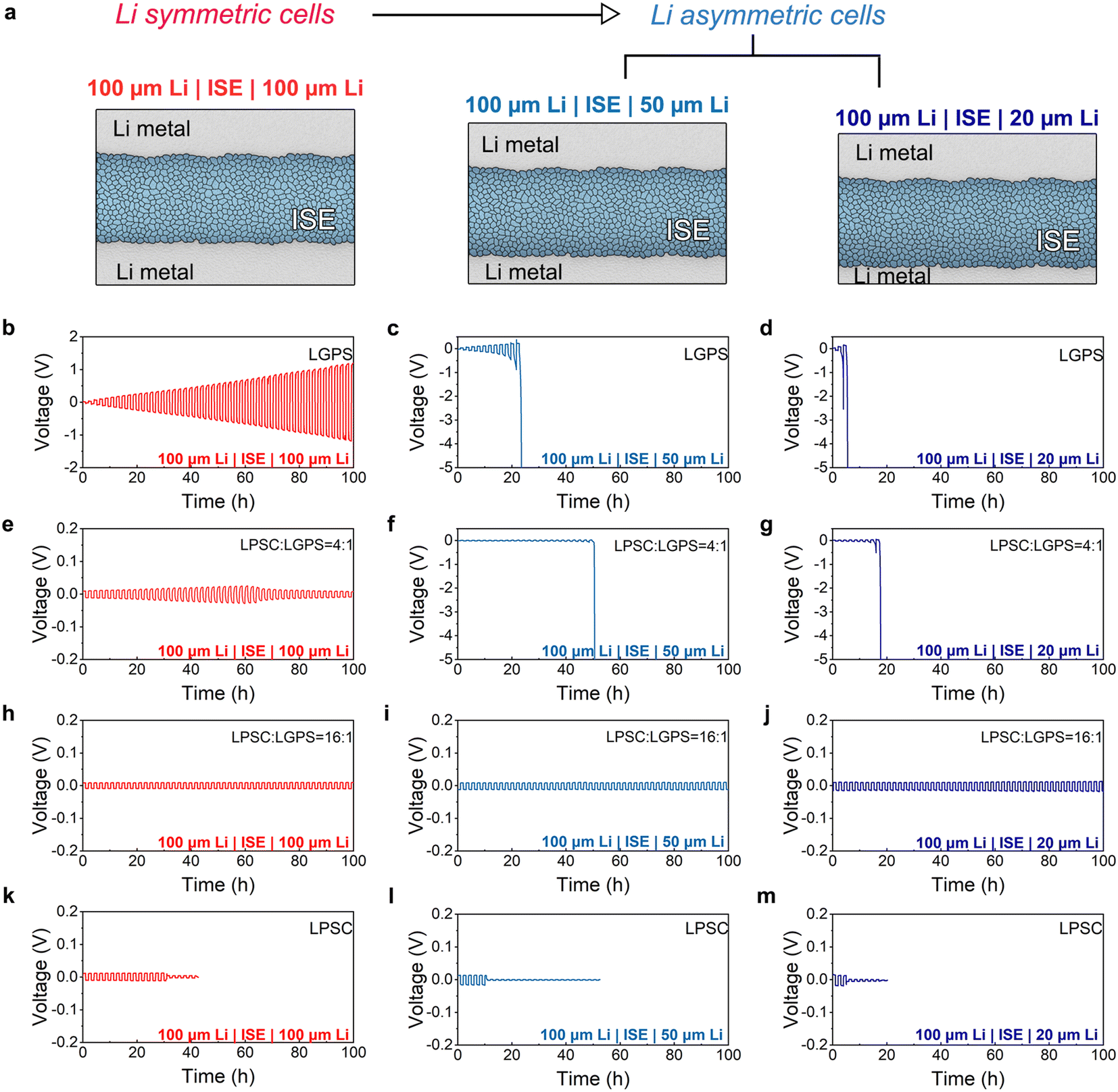 | ||
Fig. 2 (a) The schematic diagram of Li symmetric and asymmetric cells used in the evaluation. (b–d) Voltage profiles of the 100 μm thick Li|LGPS|100 μm thick Li symmetric cell (b), 100 μm thick Li|LGPS|50 μm thick Li (c) and 100 μm thick Li|LGPS | 20 μm thick Li asymmetric cells (d). (e–g) Voltage profiles of the 100 μm thick Li|LPSC![[thin space (1/6-em)]](https://www.rsc.org/images/entities/char_2009.gif) :LGPS = 4:1|100 μm thick Li symmetric cell (e), 100 μm thick Li|LPSC:LGPS = 4:1|50 μm thick Li (f) and 100 μm thick Li|LPSC:LGPS = 4:1|20 μm thick Li asymmetric cells (g). (h–j) Voltage profiles of the 100 μm thick Li|LPSC:LGPS = 16:1|100 μm thick Li symmetric cell (h), 100 μm thick Li|LPSC:LGPS = 16:1|50 μm thick Li (i) and 100 μm thick Li|LPSC:LGPS = 16:1|20 μm thick Li asymmetric cells (j). (k–m) Voltage profiles of the 100 μm-thick Li|LPSC|100 μm thick Li symmetric cell (k), 100 μm Li|LPSC|50 μm thick Li (l) and 100 μm thick Li|LPSC|20 μm thick Li asymmetric cells (m). :LGPS = 4:1|100 μm thick Li symmetric cell (e), 100 μm thick Li|LPSC:LGPS = 4:1|50 μm thick Li (f) and 100 μm thick Li|LPSC:LGPS = 4:1|20 μm thick Li asymmetric cells (g). (h–j) Voltage profiles of the 100 μm thick Li|LPSC:LGPS = 16:1|100 μm thick Li symmetric cell (h), 100 μm thick Li|LPSC:LGPS = 16:1|50 μm thick Li (i) and 100 μm thick Li|LPSC:LGPS = 16:1|20 μm thick Li asymmetric cells (j). (k–m) Voltage profiles of the 100 μm-thick Li|LPSC|100 μm thick Li symmetric cell (k), 100 μm Li|LPSC|50 μm thick Li (l) and 100 μm thick Li|LPSC|20 μm thick Li asymmetric cells (m). | ||
As the evaluation results demonstrate, the use of Li asymmetric cells offers a distinct advantage over Li symmetric cells in terms of reliability and accuracy when assessing the detrimental effects of MIIs. For MII-1 with a very high Vf-M (generated from the reduction of pure LGPS), only a continuous increase in polarization can be observed when evaluated using the conventional Li symmetric cell (Fig. 2b). However, when assessed using the Li asymmetric cell, MII-1 can cause the cell's voltage to exceed the test range of the instrument (±5 V) rapidly, signaling a swift depletion of lithium on one side (Fig. 2c and d). For MII-2 with a relatively high Vf-M (generated from the reduction of LPSC:LGPS = 4:1), evaluations based on conventional Li symmetric cells would be completely invalidated. The Li symmetric cell paired with MII-2 demonstrates a minimal increase in polarization (Fig. 2e). The maximum value of the cell polarization is 26 mV, only two times higher than that of the Li symmetric cell paired with the metal-free SEI (generated from the reduction of LPSC). However, the cycle life of the Li symmetric cell paired with MII-2 is three times longer than that of the Li symmetric cell paired with the metal-free SEI (Fig. 2k). This may lead to an illusion that employing such a MII improves the reversibility of Li metal. Nevertheless, the Li asymmetric cells paired with MII-2 shows that the Li consumption occurred violently, indicating that the “promising” result presented by MII-2 in the Li symmetric cell test is actually misleading (Fig. 2f and g). Besides, after 60 h cycling, the Li symmetric cell paired with MII-2 shows a decrease in polarization. Some reports have attributed similar cases as a so-called “activation process”.27 Considering that the detrimental effects of MII-2 are not suppressed to a neglectable level, we argue that this phenomenon may be induced by the deposition of Li metal within MII-2. Additionally, based on the above results, we observe that Li asymmetric cells assembled with a 20 μm thick Li electrode reflect the detrimental effects of MIIs in a shorter timeframe compared to those assembled with a 50 μm thick Li electrode. Therefore, we encourage conducting pre-experiments with Li asymmetric cells assembled with the thinnest feasible metallic lithium electrodes for the convenience of evaluating the MII.
Next, to address the question of whether the detrimental effects of MIIs can be reduced to negligible levels, we evaluated MII-3 with a very low Vf-M (generated from the reduction of LPSC:LGPS = 16:1) using both symmetric and asymmetric cells. Encouragingly, both the symmetric and asymmetric cells paired with MII-3 (Fig. 2h–j) demonstrated lower polarization and extended cycle life compared to symmetric cells paired with metal-free SEIs (Fig. 2k–m). Moreover, no Li depletion was observed during the evaluation based on asymmetric cells. These results experimentally confirm that MIIs with an appropriately low Vf-M can virtually eliminate their detrimental effects while retaining their beneficial properties, thus enhancing lithium reversibility. Based on this, we support the view that MIIs have the potential to enhance lithium reversibility, provided that its Vf-M is sufficiently low. The following section will explore, from a theoretical perspective, why the detrimental effects nearly vanish at an appropriately low Vf-M value and discuss what constitutes an “appropriate” low Vf-M.
The relationship between Vf-M and the electronic conductivity of MIIs
Based on the simple mixing rule (eqn (1)), given that the intrinsic electronic conductivity of metals (σM) is orders of magnitude higher than that of non-metallic components (σNM), even a minimal introduction of metals can lead to a substantial increase in electronic conductivity of the MII (σMII). This forms the basis of the argument against the MII's potential to enhance Li reversibility. However, this theoretical view contradicts our experimental observations presented above. Therefore, a more scientific and accurate theoretical framework is needed to explain the relationship between the metal content and the electronic conductivity of the interphase.| σMII = VfσM + (1 − Vf)σNM | (1) |
As there is currently no dedicated research systematically establishing such a relationship, we draw insights from the studies on composites of electronically insulating polymers and electronically conductive agents, which share considerable similarities with MIIs.28,29 In these composites, the correlation between the volume fraction (Vf) of electronically conductive agents and the electronic conductivity of composites can be determined using the percolation theory. In percolation theory, a crucial concept is the percolation threshold, representing the fraction of points that must be filled to establish a continuous path of nearest neighbors from one side to another. As for the composite of electronically conductive and electronically insulating agents, when the Vf of electronically conductive agents surpasses the percolation threshold, either through direct contact or electron tunneling effects, electronically conductive agents gradually form a continuous electron-conducting network. At this point, the electronic conductivity of the composite increases exponentially with the introduction of electronically conductive agents. At a Vf lower than the percolation threshold, electronically conductive agents are separated by substantial amounts of electronically insulating agents, and a continuous percolation network for electron conduction does not form. In this situation, the electronic conductivity of the composite approaches that of electronically insulating agents. This theory provides a plausible explanation for why the detrimental effects of MII-3 are nearly eliminated, despite the presence of metals (Fig. 3). The key lies in the fact that the Vf-M of MII-3 is below the percolation threshold, and thus the electron transport is entirely hindered by the insulating phase.
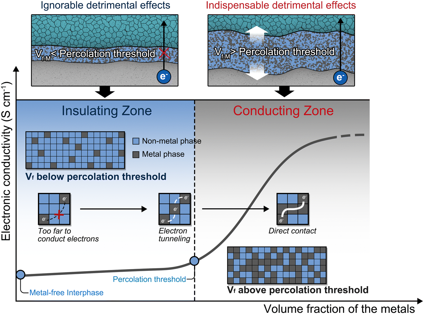 | ||
| Fig. 3 The application of the percolation theory in the metal-incorporated interphase. | ||
Typically, the measurement of the percolation threshold in mixed conducting composites is achieved by iteratively incorporating the Vf of the conductive agent and the electronic conductivity into the percolation equation (eqn (2)), where σ0 is the bulk electronic conductivity of the conducting agent, VP is the percolation threshold, σ is the electronic conductivity of the composite, and n is the fitting exponent.
| σ = σ0·(Vf – VP)n | (2) |
Nevertheless, within the framework of ASSLMBs, ascertaining the percolation threshold presents a formidable challenge attributed to the intricacy associated with independently measuring the electronic conductivity of the interphase.30 Therefore, we look forward to the development of advanced electrochemical measurement techniques to address this challenge.
Outlook: future directions in designing metal incorporated-SEIs
Based on the above discussion, when the Vf-M falls below the percolation threshold, the MII almost loses its electron transport capability. Similar to the SEI, this type of MII also exhibits the characteristics of self-limiting growth through our critical evaluations. Therefore, we suggest referring to this type of MII as the “metal incorporated-SEI (MI-SEI)” to distinguish it from other MIIs. Due to its promising capability of enhancing Li reversibility, the MI-SEI is poised to become the focal point in the ongoing research of Li/ISE interfaces. We attempt to depict the following directions in the future design of the MI-SEI (Fig. 4). | ||
| Fig. 4 Future directions in designing the MI-SEI. | ||
Elevating the percolation threshold
Below the percolation threshold, the detrimental effects of metals are suppressed to an ignorable level, and the beneficial effects increase with the enhancing Vf-M. Based on this, the MI-SEI theoretically reaches its maximum potential in enhancing Li reversibility when its Vf-M approaches the percolation threshold. Consequently, raising the percolation threshold can further augment the maximum Vf-M within the MI-SEI, thereby enhancing MI-SEI's capacity to improve the reversibility of Li. Previous studies on polymer/conductive agent composites can provide valuable insights into methods for increasing the percolation threshold.31 For instance, different metal particles may exhibit varying aspect ratios (AR), where AR is defined as the ratio between the longest and shortest dimensions of a particle, serving as a parameter to describe its shape. As particles approach a spherical shape, their AR values decrease, resulting in higher achievable percolation thresholds. Additionally, the percolation threshold is closely linked to the size of conductive particles. Under the same Vf of particles, larger particle sizes lead to higher percolation thresholds. In addition to those techniques, we assert that the distribution pattern of metals can influence the percolation threshold of the resulting MII. In our mind, if metals and non-metal particles are not randomly distributed in the interphase but rather designed such that the non-metal particles envelop the metal particles, the formation of a percolation network for metals may become more challenging. Given the current lack of understanding regarding the microstructure and distribution of the metallic phase within MIIs, it is crucial to employ advanced characterization techniques to study the MII in order to facilitate the successful implementation of the strategies mentioned above.Promoting the beneficial effects
Li alloys commonly demonstrate higher Li affinity than metallic phases that cannot alloy with Li.32 In addition, Li alloys additionally offer the merit of high Li diffusivity compared to their non-alloyed counterparts. Therefore, we recommend prioritizing the introduction of Li alloys into the MI-SEI. To boost the beneficial effects, one should screen for Li alloys that simultaneously possess high Li affinity and high Li diffusivity. The simplest method to assess Li affinity is testing the contact angle between Li and the Li alloy substrate. Li alloy materials with a higher Li affinity will show a lower contact angle with molten Li.32 For Li diffusivity, isotope tracer tests can determine the Li diffusion coefficient.33 Aside from experimental methods, high-throughput theoretical calculations of the work of adhesion between Li and the alloy, as well as the lithium diffusion barrier in Li alloys calculated by the climb image-nudged elastic band (CI-NEB) method, can assist in screening Li alloy materials with high Li affinity and high Li diffusivity, respectively.21,34,35Conclusions
In summary, we propose that the use of Li asymmetric cells offers a more accurate and reliable method for evaluating MIIs compared to conventional Li symmetric cells. Through a comparative analysis of the evaluation results from Li symmetric and asymmetric cells, we discover that when assessing MIIs with a very high Vf-M, Li symmetric cells only exhibit increased polarization, while the voltage of Li asymmetric cells exceeds the test range of the instrument rapidly due to Li depletion. Moreover, when evaluating MIIs with a relatively high Vf-M, testing results from Li symmetric cells can be highly misleading, whereas the use of Li asymmetric cells effectively avoids such misleading outcomes. Additionally, we observed that MIIs with sufficiently low Vf-M can significantly improve Li reversibility. Drawing insights from percolation theory, we argue that when Vf-M is below the percolation threshold, the undesirable electronic conduction of MIIs can be effectively suppressed. Therefore, we advocate for the design of MIIs as an effective approach to enhance lithium reversibility, provided that the Vf-M is below the percolation threshold. Lastly, we propose two strategies for MII design: one aimed at increasing the percolation threshold and another focused on promoting beneficial effects. We believe that this perspective provides valuable guidance for future evaluations of MIIs and offers insights for the design of Li/ISE interfaces in upcoming research.Experimental section
Preparation of LPSC, LGPS and LPSC/LGPS composite electrolytes
The LPSC and LGPS electrolytes were prepared via the following approach. As for the LPSC electrolytes, stoichiometric Li2S (99.99%, Sigma-Aldrich), P2S5 (99.9%, Sigma-Aldrich) and LiCl (99.9%, Sigma-Aldrich) were mechanically milled at 550 rpm for 20 h. Then, as-milled precursors obtained from the ball milling process was further annealed at 550 °C for 5 h to yield the final LPSC products. As for the LGPS electrolytes, stoichiometric Li2S (99.99%, Sigma-Aldrich), P2S5 (99.9%, Sigma-Aldrich) and GeS2 (99.9%, Sigma-Aldrich) were mechanically milled at 550 rpm for 20 h. Then, as-milled precursors obtained from the ball milling process was further annealed at 550 °C for 24 h to yield the final LGPS products. The LPSC/LGPS composite electrolytes were prepared by mechanically milling the LPSC and LGPS electrolytes with an appropriate ratio together at 110 rpm for 1 h.Cell assembly and electrochemical tests
Both the Li symmetric and Li asymmetric cells were assembled in the Ar-filled glovebox (H2O < 0.1 ppm, O2 < 0.1 ppm). For Li symmetric cells, electrolyte pellets were prepared by cold pressing electrolyte powder (150 mg) at 360 MPa inside the poly (ether–ether–ketone) (PEEK) mold with a diameter of 10 mm.36 Then, two 100 μm thick Li foils with a diameter of 10 mm were pressed onto both sides of the electrolyte layer under 30 MPa for 5 min. For the preparation of Li asymmetric cells, one electrode side of the Li asymmetric cell employed a 50 μm thick or 20 μm thick Li foil, while the other electrode side used a 100 μm thick Li foil. Apart from this, all other assembly processes remained consistent with those of Li symmetric cells. The galvanostatic discharging/charging tests were conducted on the Neware CT-4008 battery test system.Author contributions
J.P.T. and H.S. conceived the perspective article. H.S. and J.M.F. conducted relevant literature reviews and wrote the initial manuscript. H.S., J.M.F. and Y.Z. proposed the protocol to evaluate the metal-incorporated interphase. The verification experiments were carried out by S.F.L., J.E.K, M.K.W., H.S., J.M.F., Y.H. and X.L.W. Y.Z. designed the figures. Y.Z., X.L.S, and J.P.T provided supervision throughout the manuscript-writing process. H.S. and J.M.F. contributed equally to this work.Data availability
The data in Fig. 2 are available in Google Sheets at https://docs.google.com/spreadsheets/d/1qj_Bzgk2x1lpPs0qyI5Fpgko2Ket-gBHRyXM9SJLH70/edit?usp=sharing.Conflicts of interest
There are no conflicts to declare.Acknowledgements
This work is supported by the National Natural Science Foundation of China (Grant No. U20A20126, 52103350, 52472109), the “Pioneer” and “Leading Goose” R&D Program of Zhejiang (grant. no. 2025C01181), and the Key Research and Development Program of Zhejiang Province (2022C01071). Prof. X. L. Sun acknowledges the support from the Natural Sciences and Engineering Research Council of Canada (NSERC), the Canada Research Chair Program (CRC), the Canada Foundation for Innovation (CFI), the Ontario Research Fund, and the University of Western Ontario.References
- J. G. Zhang, W. Xu, J. Xiao, X. Cao and J. Liu, Chem. Rev., 2020, 120, 13312–13348 CrossRef CAS PubMed.
- N. Nitta, F. X. Wu, J. T. Lee and G. Yushin, Mater. Today, 2015, 18, 252–264 CrossRef CAS.
- Y. Li, X. Feng, D. Ren, M. Ouyang, L. Lu and X. Han, ACS Appl. Mater. Interfaces, 2019, 11, 46839–46850 CrossRef CAS PubMed.
- J. X. Hou, L. G. Lu, L. Wang, A. Ohma, D. S. Ren, X. Feng, Y. Li, Y. L. Li, I. Ootani, X. B. Han, W. N. Ren, X. He, Y. Nitta and M. G. Ouyang, Nat. Commun., 2020, 11, 5100 CrossRef CAS PubMed.
- J. Janek and W. G. Zeier, Nat. Energy, 2016, 1, 141 Search PubMed.
- A. Manthiram, X. W. Yu and S. F. Wang, Nat. Rev. Mater., 2017, 2, 16103 CrossRef CAS.
- T. Famprikis, P. Canepa, J. A. Dawson, M. S. Islam and C. Masquelier, Nat. Mat., 2019, 18, 1278–1291 CrossRef CAS PubMed.
- T. Krauskopf, F. H. Richter, W. G. Zeier and J. Janek, Chem. Rev., 2020, 120, 7745–7794 CrossRef CAS PubMed.
- Y. H. Xiao, Y. Wang, S. H. Bo, J. C. Kim, L. J. Miara and G. Ceder, Nat. Rev. Mater., 2019, 5, 105–126 CrossRef.
- Z. Wang, J. Zhao, X. Zhang, Z. Rong, Y. Tang, X. Liu, L. Zhu, L. Zhang and J. Huang, eScience, 2023, 3, 100087 CrossRef.
- Y. Z. Zhu, X. F. He and Y. F. Mo, ACS Appl. Mater. Interfaces, 2015, 7, 23685–23693 CrossRef CAS PubMed.
- N. Kamaya, K. Homma, Y. Yamakawa, M. Hirayama, R. Kanno, M. Yonemura, T. Kamiyama, Y. Kato, S. Hama, K. Kawamoto and A. Mitsui, Nat. Mat., 2011, 10, 682–686 CrossRef CAS PubMed.
- Z. H. Zhang, S. J. Chen, J. Yang, J. Y. Wang, L. L. Yao, X. Y. Yao, P. Cui and X. X. Xu, ACS Appl. Mater. Interfaces, 2018, 10, 2556–2565 CrossRef CAS PubMed.
- H. Su, Z. Jiang, Y. Liu, J. R. Li, C. D. Gu, X. L. Wang, X. H. Xia and J. P. Tu, Energy Mater., 2022, 2, 200005 Search PubMed.
- S. Wenzel, D. A. Weber, T. Leichtweiss, M. R. Busche, J. Sann and J. Janek, Solid State Ionics, 2016, 286, 24–33 CrossRef CAS.
- B. B. Chen, J. W. Ju, J. Ma, J. Zhang, R. Xiao, G. Cui and L. Chen, Phys. Chem. Chem. Phys., 2017, 19, 31436–31442 RSC.
- Y. Lu, C. Z. Zhao, J. K. Hu, S. Sun, H. Yuan, Z. H. Fu, X. Chen, J. Q. Huang, M. G. Ouyang and Q. Zhang, Sci. Adv., 2022, 8, eadd0510 CrossRef CAS PubMed.
- H. L. Wan, Z. Y. Wang, S. F. Liu, B. Zhang, X. Z. He, W. R. Zhang and C. S. Wang, Nat. Energy, 2023, 8, 473–481 CrossRef CAS.
- J. S. Yoon, D. W. Liao, S. M. Greene, T. H. Cho, N. P. Dasgupta and D. J. Siegel, ACS Appl. Mater. Interfaces, 2024, 16, 18790–18799 CrossRef CAS PubMed.
- H. Su, Y. Liu, Y. Zhong, J. R. Li, X. L. Wang, X. H. Xia, C. D. Gu and J. P. Tu, Nano Energy, 2022, 96, 107104 CrossRef CAS.
- T. R. Wang, J. Duan, B. Zhang, W. Luo, X. Ji, H. H. Xu, Y. Huang, L. Q. Huang, Z. Y. Song, J. Y. Wen, C. S. Wang, Y. H. Huang and J. B. Goodenough, Energy Environ. Sci., 2022, 15, 1325–1333 RSC.
- Y. C. Yin, J. T. Yang, J. D. Luo, G. X. Lu, Z. Huang, J. P. Wang, P. Li, F. Li, Y. C. Wu, T. Tian, Y. F. Meng, H. S. Mo, Y. H. Song, J. N. Yang, L. Z. Feng, T. Ma, W. Wen, K. Gong, L. J. Wang, H. X. Ju, Y. Xiao, Z. Li, X. Tao and H. B. Yao, Nature, 2023, 616, 77–83 CrossRef CAS PubMed.
- Z. X. Wang, Y. Jiang, J. Wu, Y. Jiang, W. C. Ma, Y. R. Shi, X. Y. Liu, B. Zhao, Y. Xu and J. J. Zhang, Nano Energy, 2021, 84, 105906 CrossRef CAS.
- C. Liu, B. T. Chen, T. R. Zhang, J. C. Zhang, R. Y. Wang, J. Zheng, Q. J. Mao and X. F. Liu, Angew. Chem., Int. Ed., 2023, 62, e202302655 CrossRef CAS PubMed.
- B. W. Taklu, W. N. Su, Y. Nikodimos, K. Lakshmanan, N. T. Temesgen, P. X. Lin, S. K. Jiang, C. J. Huang, D. Y. Wang, H. S. Sheu, S. H. Wu and B. J. Hwang, Nano Energy, 2021, 90, 106542 CrossRef CAS.
- S. Li, S. J. Yang, G. X. Liu, J. K. Hu, Y. L. Liao, X. L. Wang, R. Wen, H. Yuan, J. Q. Huang and Q. Zhang, Adv. Mater., 2024, 36, 2307768 CrossRef CAS PubMed.
- H. Duan, C. H. Wang, R. Z. Yu, W. H. Li, J. M. Fu, X. F. Yang, X. T. Lin, M. Zheng, X. N. Li, S. X. Deng, X. G. Hao, R. Y. Li, J. T. Wang, H. Huang and X. L. Sun, Adv. Energy Mater., 2023, 13, 2300815 CrossRef CAS.
- T. Khan, M. S. Irfan, M. Ali, Y. Dong, S. Ramakrishna and R. Umer, Carbon, 2021, 176, 602–631 CrossRef CAS.
- J. Doh, S. I. Park, Q. Yang and N. Raghavan, Carbon, 2021, 172, 308–323 CrossRef CAS.
- P. Bron, B. Roling and S. Dehnen, J. Power Sources, 2017, 352, 127–134 CrossRef CAS.
- L. D. S. Vieira, E. G. R. dos Anjos, G. E. A. Verginio, I. C. Oyama, N. F. Braga, T. F. da Silva, L. S. Montagna and F. R. Passador, Nano Sel., 2021, 3, 248–260 CrossRef.
- S. H. Wang, J. Yue, W. Dong, T. T. Zuo, J. Y. Li, X. Liu, X. D. Zhang, L. Liu, J. L. Shi, Y. X. Yin and Y. G. Guo, Nat. Commun., 2019, 10, 4930 CrossRef PubMed.
- M. Siniscalchi, J. Liu, J. S. Gibson, S. J. Turrell, J. Aspinall, R. S. Weatherup, M. Pasta, S. C. Speller and C. R. M. Grovenor, ACS Energy Lett., 2022, 7, 3593–3599 CrossRef CAS PubMed.
- X. Liang, Q. Pang, I. R. Kochetkov, M. S. Sempere, H. Huang, X. Sun and L. F. Nazar, Nat. Energy, 2017, 2, 17119 CrossRef CAS.
- R. Wang, J. Yu, J. T. Tang, R. J. Meng, L. F. Nazar, L. Z. Huang and X. Liang, Energy Storage Mater., 2020, 32, 178–184 CrossRef.
- Z. Wu, S. He, C. Zheng, J. Gan, L. She, M. Zhang, Y. Gao, Y. Yang and H. Pan, eScience, 2024, 4, 100247 CrossRef.
Footnote |
| † These authors contributed equally to this work. |
| This journal is © The Royal Society of Chemistry 2025 |