
 Open Access Article
 This Open Access Article is licensed under a
 Creative Commons Attribution 3.0 Unported Licence
Non-linear cracking response to voltage revealed by operando X-ray tomography in polycrystalline NMC811†
Huw C. W.
Parks
 abc,
Matthew P.
Jones
a,
Aaron
Wade
ac,
Alice V.
Llewellyn
ac,
Chun
Tan
ac,
Hamish T.
Reid
ab,
Ralf
Ziesche
de,
Thomas M. M.
Heenan
ac,
Shashidhara
Marathe
d,
Christoph
Rau
d,
Paul R.
Shearing
acf and
Rhodri
Jervis
*abc
abc,
Matthew P.
Jones
a,
Aaron
Wade
ac,
Alice V.
Llewellyn
ac,
Chun
Tan
ac,
Hamish T.
Reid
ab,
Ralf
Ziesche
de,
Thomas M. M.
Heenan
ac,
Shashidhara
Marathe
d,
Christoph
Rau
d,
Paul R.
Shearing
acf and
Rhodri
Jervis
*abc
aElectrochemical Innovation Lab, Department of Chemical Engineering, University College London, London, WC1E 6BT, UK. E-mail: Rhodri.Jervis@ucl.ac.uk
bAdvanced Propulsion Lab, Department of Chemical Engineering, University College London, London, WC1E 6BT, UK
cThe Faraday Institution, Quad One, Harwell Campus, Didcot, OX11 0RA, UK
dDiamond Light Source, Harwell Science & Innovation Campus, Didcot, OX11 0DE, UK
eHelmholtz-Zentrum Berlin für Materialien und Energie (HZB), Hahn-Meitner-Platz 1, 14109 Berlin, Germany
fThe Zero Institute, Oxford Dept Engineering Science, University of Oxford, Parks Road, Oxford, OX1 3PJ, UK
First published on 12th March 2025
Abstract
To understand fracture behaviour in battery materials, X-ray computed tomography (X-ray CT) has become the primary technique for non-destructive particle and crack analysis. Cracking causes performance decline in polycrystalline NMC811 by exposing new surfaces for parasitic electrolyte reactions and disconnecting active material from the electrode matrix. First cycle crack formation has been documented, but definitive electrochemically induced particle fracture is challenging to assess due to complex sample preparation and high-resolution X-ray imaging requirements. Presented here is an operando X-ray CT technique that enables accurate observation of fracture behaviour during de-/lithiation. A non-linear relationship between fracture behaviour and cell voltage was uncovered, and evidence of particle reformation during re-lithiation. Using a grey level analysis algorithm for fracture detection, we expedite damage evaluation in several thousands of particles throughout the electrochemical process, understanding crack initiation, propagation, and closure on a large, statistical scale and give the ability to track any one of the thousands of particles through its individual electrochemical history. Additionally, we explore the effects of continued volumetric hysteresis on particle damage. For the first time, we demonstrate the complex plurality of fracture behaviour in commercial lithium-ion battery materials, aiding in designing mitigation strategies against particle fracture.
Broader contextThis article presents for the first time a truly operando 4D study on the cracking behaviours within pertinent battery cathode particles, and presents a novel technique coupled with rapid grey level analysis algorithm for other electrochemical systems to adopt. The data sets alone mark a clear step forward for validation of fracture models and the understanding of processes that may be occurring in the particle structure that fails to be acquired with previous micro tomography. The data set is one of a kind micro-CT that we have made openly accessible for others to use in further analysis or computational modeling. The transition to batteries as an energy storage medium for the decarbonisation of transport sector hinges on the lifetimes of the cells utilised, and their ability to meet the demands of consumers. This degradation analysis presents as a possible route to determine the fracture behaviour and the decline in performance at the electrode level, for not only NMC811, but for all energy storage material that requires a deeper understanding into its electrochemically induced morphological changes; commercial environments are required to be pertinent to academic, industrial, and computational studies in degradation studies utalising X-ray techniques. |
1. Introduction
Cracking in polycrystalline cathode materials has been considered detrimental to cell performance as it exposes fresh surfaces to electrolyte, reduces effective ionic and electronic conduction pathways, and can facilitate the formation of inactive regions over time.1,2 Cracking has traditionally been attributed to unit cell anisotropic volumetric hysteresis after extended cycling, as studies often observe cracking in discharged (lithiated) battery materials typically after many cycles.3 However, recent findings suggest that high voltages in the first cycle can also induce immediate intergranular cracking, initiating degradation pathways before ageing begins.3–5 This phenomenon may reduce early cycle performance by exposing fresh surfaces to parasitic reactions with the electrolyte; However, first cycle losses are generally attributed to solid electrolyte interphase (SEI) on the graphite anode, and therefore cracking present in early cycles may not appear to be catastrophic to cell performance initially.2 Additionally, oxygen release can coincide with crystallographic reconstruction into an inactive reduced surface layer, and eventually a rock-salt (Fm![[3 with combining macron]](https://www.rsc.org/images/entities/char_0033_0304.gif) m) phase.6–10
m) phase.6–10
Cracking is a complex mechanism, with the extent of cracking influenced by a variety of factors including: particle size, temperature, C-rate, electrolyte composition, and cycle number.11 Therefore, to visualise these defects for quantification, advanced imaging techniques such as cross sectional scanning electron microscopy (SEM) have been used after cell ageing.12,13 However, for non-destructive imaging X-ray computed tomography (XCT) has been vital in imaging NMC materials at a number of length scales,14 and advanced segmentation methods have help to quantify the cracking and degradation within particles and at an electrode level.15–17 X-ray computed tomography of raw NMC622 and 811 powders showed there was some cracking and void formation before being fabricated into printed electrodes,18 and once fabricated, additional defects can be seen to be introduced into the secondary agglomerates, presumably due to the pressure exerted during calendaring.14,19 As well as physical experiments, a plethora of literature is devoted to modelling defects and fracture present in prominent battery materials.20–23 The literature reports a myriad of electrochemically induced fracture behaviours that present themselves in NMC, and especially NMC811 where large anisotropic crystallographic volume changes throughout cycling promotes heterogenous mechanical forces within the secondary agglomerates.2,24 It has also been reported that the continual crystal volume hysteresis will cause fatigue in the NMC lattice structure, sequestering parts of the material and reducing overall cell performance.3,7 However, cracking has more recently been reported to be severe even in the first cycle, and therefore a more careful study into the effects of early cycle cracking phenomena on the longevity of the battery must be considered.5
To understand cracking in NMC811 some experiments have used electrochemical impedance spectroscopy (EIS) to quantify cracking by detecting increased surface area.25 To observe these structural defects in NMC, the use of X-ray techniques has dominated characterisation efforts; in particular, operando diffraction in NMC811 and 3D characterisation of larger defects by X-ray computed tomography (X-ray CT).26,27 This work builds upon previous XCT efforts and introduces advanced in situ tomography methods to enable direct observation of voltage-mediated particle fracturing on the same particles during charge and discharge, testing the hypothesis that cracks form early during charging and partially close upon discharge.4 Previously, imaging of particles in their discharged state is likely to miss this effect, leading to the conclusion that minimal cracking occurs during initial cycles. However, recent studies suggest that electrochemically induced cracking can occur as early as the first cycle.3,4,28 These works, whilst informative, either do not register the initial condition of the particles, or the particle are at risk of being pre-damaged by the imaging method (in this particular case, damage caused by focused ion beam scanning electron microscopy (FIB-SEM))3 and therefore does not constitute a typical cathode active material environment. As with all operando techniques, matching the real working environment as closely as possible during measurement is paramount for reliable insight from the characterisation method.
We believe an operando study tracking particles from their known initial state is essential for understanding cracking behaviour. Earlier attempts to describe first-cycle cracking have been limited by undefined starting conditions or inconsistent samples between pristine and cycled electrodes, often leading to speculative conclusions.4,19 Here, the initial condition of each particle is known, allowing us to track crack propagation on a particle-by-particle basis across multiple states-of-charge (SoC) within a commercial electrode. Previously, we conducted a pseudo in situ study using nano X-ray CT (125 nm resolution) to track particles during charging. However, the small field of view (FoV), requirement for a small sample (<100 μm) and extensive post-processing limited the analysis to only a few particles.5 Our imaging method presented here, in conjunction with a grey level analysis algorithm for defect detection,29 enables rapid assessment of over 7000 particles at multiple states-of-charge (SoC), revealing how particle delithiation state influences cracking behaviour. Additionally, we tracked ongoing fracturing in the same electrode over 10 subsequent cycles, offering insight into how first-cycle cracking propagates during the early life of the cell, offering potential insights that will improve the lifetime of NMC811 cells under particular conditions.
2. Results and discussion
2.1. Manual particle analysis
Successful imaging of electrode cracking relies on sufficient contrast between the mass attenuation coefficients of the active material and the void spaces created by cracks. X-ray attenuation is directly related to the thickness and density of the material it penetrates, causing voids within the NMC secondary particles to appear as darker regions in the XCT images (Fig. S4a–d and S11b–d†).30 The intensity of each voxel is related to materials attenuation within, following a version of the Beer–Lambert law.4 Greyscale intensity is inversely proportional to X-ray attenuation, so voxels containing voids appear darker than those with NMC material. If a voxel contains both NMC and a crack, the greyscale intensity is reduced, representing a linear combination of the two materials compared to pure NMC (termed ‘the partial volume effect’).31 A voxel fully filled with void/crack shows minimal attenuation, resulting in an extremely low greyscale value. This partial averaging, or partial volume effect, arising from the mixing of NMC and void materials within the same voxel and allows for the detection and quantification of defects that are not visible in the tomogram by eye.31 Moreover, the greyscale intensity reduction also reflects internal damage, such as cracking, within the particles, and the lower the particle average greyscale the more damaged it may be. Leveraging this phenomenon allows us to obtain information about the extent of defects beyond the spatial resolution of the imaging instrument. This has been observed previously in Wade et al.30 This demonstrates that high-resolution imaging is not necessary to provide conclusive evidence of cracking occurring within the first cycle. It is also well-established that lower-resolution imaging is sufficient for crack detection, as shown by Heenan et al., when artificially reducing the resolution of a cracked particle, the essential information needed for quantifying fracturing is retained (see Fig. S18†).32Crack features below the resolution limit of the synchrotron microscope (<325 nm voxel size) are difficult to detect visually, making it challenging to identify significant defects through visual inspection of the tomogram alone, unlike in higher resolution imaging such as nano-CT or SEM. Within our group we have previously shown the cracking behaviour in NMC811 at a number of different SoCs using ex situ samples, which also show the same cracking architecture from centre to edge.4,5 We have proven that greyscale (pixel intensity) analysis is an effective method for crack assessment in this case, where reduced attenuation and lower pixel intensity indicate voids and fracturing, as described above. While the lithium content in the crystal structure varies with lithiation state, its effect on incident energy or impurity presence is negligible. Heenan et al., calculated the changing mass attenuation coefficient of NMC811 at different lithiation states and found that the impact of lithiation is negligible, orders of magnitude less than the background noise,32 and thus we can confirm that the reduction of grey levels within a particle is uniquely associated with crack or void formation.
The lowest attenuation is observed at the centres of the particles and propagates outward, which is characteristic of electrochemically induced crack formation in these polycrystalline materials (see Fig. 1).3,4,19,21 This pattern observed here confirms that the reduction in greyscale is not due to low-attenuating lithium deposits and is a result of crack formation. Using higher resolution imaging such as FIB-SEM and nano-XCT has proven that the delithiation of NMC811 particles causes cracking, and supports that delithaitaion will cause cracking to form in the centre of particles.3,5 The approach detailed here offers advantages over higher-resolution instruments, including a larger field of view (FoV) that enables the assessment of more particles over a greater area of the electrode with statistical relevance; additionally, the sample requirements are less stringent here and allows for the use of a commercially relevant pouch cell architecture, providing more meaningful results and enabling sequential imaging of the same region across multiple electrochemical states without exposure to air or moisture.
 | ||
| Fig. 1 (a) Greyscale images of a selected particle at various voltages on charge and discharge with line scans in the X and Y direction through the particle plotted below (b & c respectively). (d & e) Show a zoomed in view of the centre of the particle (region indicated by the box in b and c), a lower pixel intensity suggests lower density, attributed to crack formation. 1 pixel is 325 nm in size, the particle shown is approximately 17.5 μm in diameter. | ||
Fig. 1 illustrates line scans of the greyscale profile in an exemplar particle. The grey scale value at the particle's centre is lower during charge (4.2 and 4.4 V) compared to the pristine and fully discharged state (2.5 V), see Fig. 1b–e. It should be noted that pure absorption contrast is not obtained during this experiment. This is clear from the brighter ‘ring’ around the particle edge that results from in-line phase contrast enhancement, and the transition of the beam through materials of different density (see Fig. 1a).33 The background does not exhibit a consistent grey level, with slight dark artefacts appearing due to the reconstruction process. However, these artefacts do not affect the NMC voxels for two main reasons: (1) if the streaking in the background were also affecting the NMC, we would observe a consistent high level of cracking in the pristine data and at all states of charge. This is not the case, as the streaks are stable in space between scans, meaning the effect would be consistent when tracking grey level changes in particles between scans. Line scan analysis shows varying values in the NMC phase at different voltages; and (2) this artefact is more likely a result of reconstruction, caused by beam hardening when X-rays pass through two phases with significantly different mass attenuation coefficients.34 Since the NMC phase has a much higher attenuation coefficient than the surrounding polymer binder and carbon additives, this texturing is specific to the background phase. This initial analysis is an indication that it is possible to confirm the presence of both cracking that has been induced due to the cell potential (lithiation state of the particle), and also particle reformation phenomenon occurring in early cycles in this data set.4,35 This manual crack identification also allows us to confirm electrochemical activity within the imaged area, which is a common concern for more bespoke operando cell designs in a variety of electrochemical systems. However, manual analysis is both laborious and non-quantitative, and thus an automated analysis of each particle in the sample volume was carried out for subsequent analysis.
2.2. Non-linear cracking response to voltage
Quantification of defects within each particle was achieved using our grey level analysis algorithm: GREAT2, which has been packaged into the GRAPES python toolkit,29 similar to that described in previous work,30 with adaptations to the original method for faster computation and deeper understanding of the particles’ behaviour. Details can be found in the methods and ESI,† with the full algorithm methodology presented in Jones et al.29 Particles were individually labelled using instance segmentation (see Fig. S4†) which facilitated the quantification of particle properties. These unique particle labels are also translated throughout all 12 X-ray CT datasets, such that particles have consistent labels through all scans, and therefore also throughout the electrochemical history. The mean pixel intensity for all particles in the area analysed was calculated and it is evident that there is a non-linear increase in damage as voltage is increased (see Fig. 2).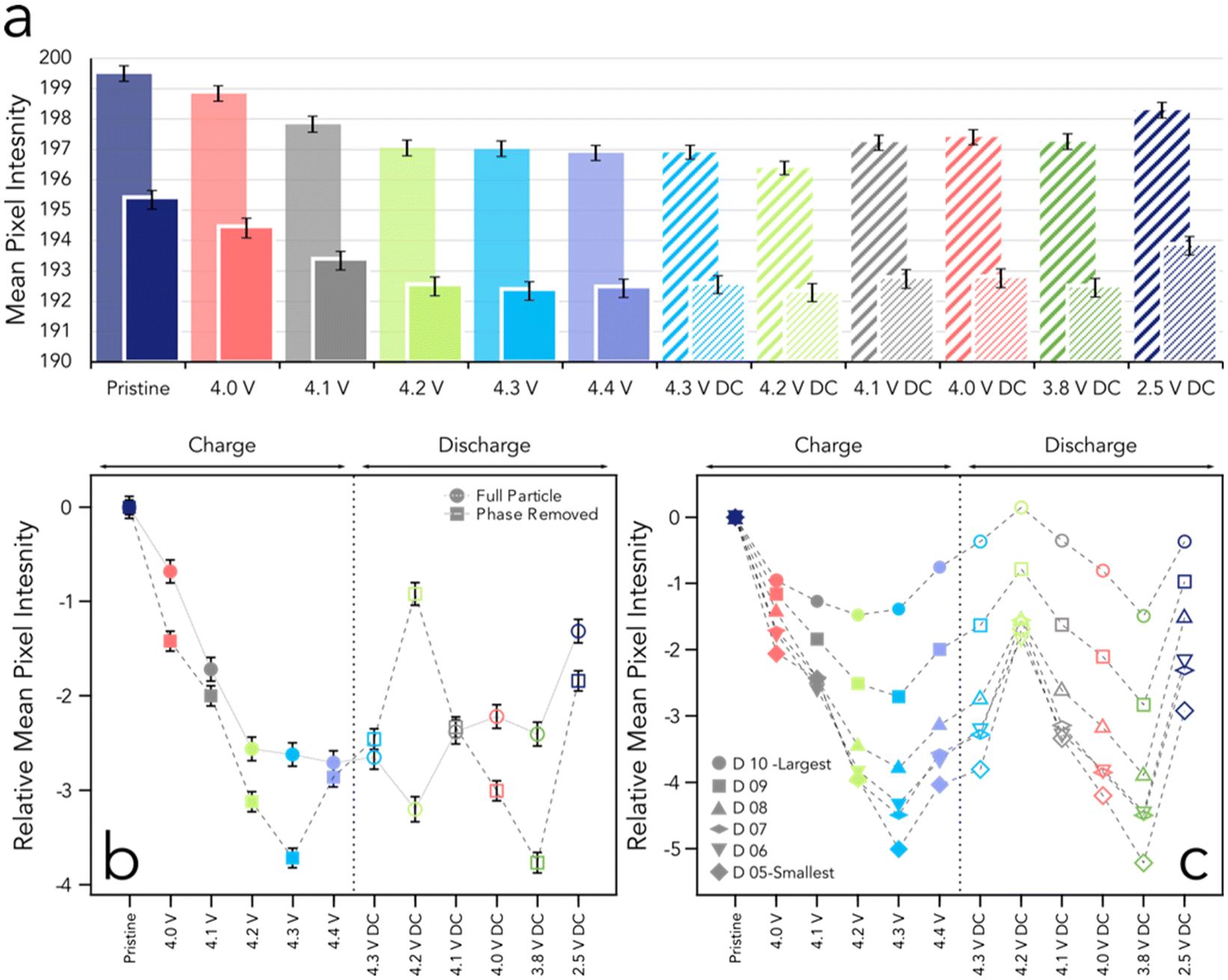 | ||
| Fig. 2 (a) Mean pixel intensity for all particles at the SoC stated, with the full particle analysis shown in transparent colours on charge and thick lines on discharge, and the central 50% in block colours on charge and thin lines on discharge (DC). (b) Relative mean pixel intensity plot with respect to particle's pristine condition for the full particle (circles) and the phase-removed portion of the particles (squares). Charging voltages are shown as filled shapes, whilst discharged voltages are unfilled. Error bars represent 2 S.E for a & b. (c) Relative mean pixel intensity plots as in part b, split into deciles. The smallest 5 deciles are omitted as they contain too few voxels for reasonable analysis. Values are presented as unit per volume (RMPI mm−3). All cell potentials are vs. Li/Li+. | ||
Radial shells (1-voxel thick layers) were defined using a distance transform from the particle surface inward. The central 50% of these shells represents the region where electrochemically induced cracking typically occurs (see Fig. S2 in the ESI† for analysis nomenclature). Analysis of mean pixel intensity shows that cracks start forming at voltages as low as 4.0 V (vs. Li/Li+), indicated by a decrease in mean intensity. This worsening continues at 4.1 V and 4.2 V but does not progress further up to 4.4 V. While one might expect cracking to increase with voltage as primary particles shrink, we find that raising the voltage above 4.2 V does not significantly impact mean radial pixel intensity during the first charge. This is curious, as cycling to voltages above 4.2 V is known to result in rapid capacity loss.10 It implies that cracking alone may not be the primary cause of capacity degradation at these voltages. Instead, electrochemical reactions on the newly-exposed surface, driven more strongly by higher potential, likely contribute more significantly to capacity loss.10,36 Similar observations have been made in ex situ studies of NMC cathodes and imply that other mechanisms, such as oxygen loss, transition metal dissolution and electrolyte oxidation, may drive capacity loss when the cell is charged beyond typical operating voltages, especially at voltages approaching 5.0 V.4
Cracking has long been linked with crystallographic activity and, more importantly, to the non-homogenous volume changes in primary particles, causing them to move and separate from each other in an anisotropic way.2,37,38 This phenomenon is commonly observed in the c-lattice, where progressive delithiation leads to a moderate expansion of the interlayer distance until about 4.15 V vs. Li/Li+. Beyond this voltage, the c-lattice parameter rapidly decreases, causing a reduction in interlayer spacing, often called c-lattice collapse.39,40 This coincides with the voltage where we initially see the most damage across the particles. At this moderate state of overall delithiation, it is possible that there exists a multiplicity of states of delithiation within different primary particles of the secondary agglomerates,41,42 possibly in a core–shell manner,43 which would lead to stresses from the secondary-particle level heterogeneities. Heterogenous lithiation has been suggested to be a contributor of higher micro-cracking within secondary particles previously, and may be a factor promoting non-linear damage behaviour here.44 According to Shishvan et al., even at high lithium homogeneity, significant particle strain arises due to a ‘mismatch between the primary particles combined with the highly anisotropic elastic and lithiation properties’, leading to a substantial strain field being induced in the secondary particle during the first charge process.23 It is also possible that dislocations within the primary particle domain may contribute to mechanical instability to induce intergranular cracking on the micro scale.45 During discharge, we observe a non-linear damage pattern with increasing lithiation. Particles worsen at 4.2 V DC but show recovery as lithiation continues (see Fig. 2a). A slight increase in damage is seen when discharging from 4.0 V to 3.8 V, indicated by lower radial pixel intensity at 3.8 V, but particles recover by 2.5 V DC, with mean pixel intensity approaching pristine levels. This suggests a reduction in voids, defects, or cracks, though small cracks may remain. Our analysis shows that primary particles within the secondary agglomerate move closer together at the end of discharge, reversing the separation seen during charging. However, we do not expect the primary particle boundaries to fully reform to the pristine state, which would require conditions such as sintering.
To better understand particle behaviour, the relative mean pixel intensity was calculated by comparing the average grey value within each particle to its pristine state. The mean of these differences was computed for the entire tomogram, as shown in Fig. 2b. This change in pixel intensity provides a quantitative measure of the particles’ evolving states during charging and discharging. Negative values indicate that the particles have sustained more damage compared to their pristine condition. The analysis revealed trends consistent with the mean particle analysis, showing that particle damage generally increases during charging. The most significant damage occurred in the voltage range of 4.2–4.4 V; however, damage progression plateaus beyond 4.2 V (see Fig. 2b, circles). This observation aligns with data in Fig. 2a, where a reduction in normalized greyscale intensity was noted up to 4.2 V, with minimal changes beyond this point.
Excluding the phase-contrast element surrounding the particle edges, continued crack formation was observed up to 4.3 V, followed by a curious recovery at 4.4 V (see Fig. 2b, squares). At these higher states of delithiation (4.4 V), most primary particles lose a significant proportion of their lithium content, leading to lattice collapse. Consequently, lithiation states among primary particles may become more homogenous, slightly reducing apparent cracking and expansion. This contrasts with states of charge in the range of 4.2–4.3 V, where a continuum of lithiation states likely exacerbates heterogeneous volume changes in primary particles.
Shishvan et al. proposed a framework based on previous nano-CT imaging conducted in this group,5,23 to explain these observations, identifying three distinct regimes during charging: (1) low State of Charge (SoC): Minimal intergranular fracture occurs, though stress builds within the particle. (2) Comminution event: Significant cracking occurs as strain energy exceeds the grain boundary energy, leading to fracture. (3) Strain dissipation: Strain energy dissipates, causing a slight reduction in particle size due to primary particle shrinkage. This framework potentially explains the observed reduction in cracking as more secondary particles transition through regime 2 to regime 3. In regime 3, the overall particle volume slightly decreases, manifesting as an increase in pixel attenuation.23
During discharge, the full particle (Fig. 2b, circles) follows a similar trend as in Fig. 2a, with a small reduction in mean pixel intensity at 4.2 V DC, before progressively becoming less cracked and recovering to a mean pixel intensity similar to the pristine state. However, for the proportion of the particle without phase contrast enhancement, recovery appears to be complete at 4.2 V DC (see Fig. 2b), followed by progressive damage as the cell discharges to 3.8 V DC. This may be due to the large volume increase within primary crystallites, especially in the c-lattice vector, during the initial 20% of discharge down to 4.2 V. As strain energy dissipates during charge, discharge behaviour is not simply the inverse of charging. Instead, the secondary particle acts more like individual primary particles, reflecting crystallographic changes. Once the lattice planes are lithiated below 4.2 V, the c-lattice contracts slightly, inducing cracking in the particles between 4.2 V and 3.8 V. When fully relithiated, the particle reaches a homogeneous lithiation state, similar to the pristine condition, with limited cracking and increased pixel intensity.
Tracking particles through datasets also allows analysis by particle size, grouping them into deciles of increasing radius (see Fig. 2c). The data here refer to the non-phase portion of each particle and are expressed per unit volume to enable size-bound comparisons (see Fig. S9 and S10 in the ESI† for total mean pixel intensity changes per decile). In Fig. 2c, all particle sizes follow a similar trend: during charging, pixel intensity progressively decreases as randomly oriented primary crystallites expand along the c-axis until 4.3 V, then slightly recover at 4.4 V, where most primary particles undergo lattice collapse and achieve homogeneity. During discharge, pixel intensity increases significantly up to 4.2 V (likely due to void filling from expanding primary particles) before showing increased damage as particles contract between 4.2 V and 3.8 V. At 2.5 V, particles partially recover, with smaller particles exhibiting the greatest recovery, though few return to pristine conditions.
2.3. Particle-by-particle analysis
The average greyscale analysis, whilst useful, does not provide us with a particle-by-particle view of the whole electrode, and thus we now define a damage factor for each particle to accurately assess the particles’ condition, and how it's condition changes with electrochemical state. Whilst looking at individual particles, a damage factor is required as the mean grey level is highly affected by particle size; damage factor looks to remove this size dependency. For specifics on damage factor calculation see glossary in ESI.†As each particle is registered carefully across all states of charge, we are able to track their damage trajectory on a particle-by-particle basis to truly understand how each particle is behaving. Fig. S10† shows that there is a number of possible damage trajectories that could be followed and that particles are following the different paths through their electrochemical journey. In Fig. 3, we apply conditional analysis to each particle to understand fully how each particle is reacting to the applied potential (i.e., at what potential does a particular particle experience its minimum or maximum damage). Typically, we see that that particles in their least damaged state occur at pristine potential, when considering the mean pixel intensity of all the particles in the electrode (see Fig. 2). We observe a similar phenomenon here, where 34% of particles exhibit their minimum damage factor in the pristine state, and only 2% show their lowest damage at the top of charge (4.3 V and 4.4 V; see Fig. 3a), indicating that particles are unlikely to remain undamaged at higher voltages. However, there is a multiplicity of different behaviours across the sample, with many particles showing their lowest damage factor at 4.0 V, 4.2 V DC, or 2.5 V DC. Notably, 15% of particles reach their minimum damage factor at 4.2 V DC. This aligns with observations of crack closure in the particle centres at 4.2 V DC, which we attribute to primary particles rapidly expanding within the core of secondary particles and filling voids created by cracking during delithiation (see Fig. S13†). This may be intuitive, until we consider where particles display their most damaged state; we calculate that 35% of particles are most damaged at 4.2 V DC.
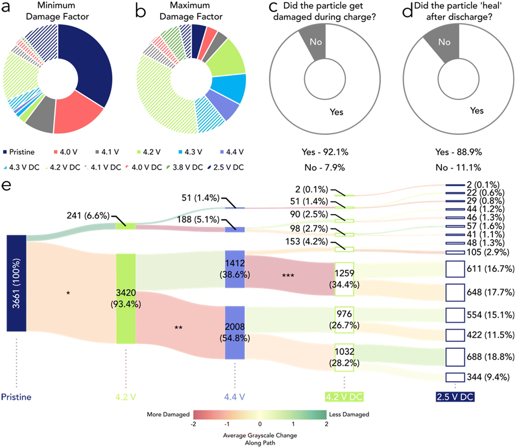 | ||
| Fig. 3 (a & b) Pie charts showing at which voltage each particle displayed it's (a) minimum and (b) maximum damage factor. (c) Pie chart showing the percentage of particles that damaged during the first charge. (d) Pie chart showing the percentage of particles that have reformed after discharged to 2.5 V. (e) Tree diagram of the largest 50% of particle's damage factors at the voltages stated, with the number of particles and the percentage of the total population stated. The colour of the path represents the degree of average greyscale change along that path and the severity can be seen in the colour bar. Asterisks (*) are to highlight notable paths referenced in the main text. | ||
We further examined how many particles sustained damage during charging to 4.4 V. Our analysis revealed that 92.1% of particles experienced some degree of damage during the charging process (see Fig. 3c). This indicates that nearly all particles exhibited a damage factor higher than their pristine state at voltages between 4.0 V and 4.4 V, aligning with previous understanding. Next, we investigated how many particles showed a reduction in their damage factor at 2.5 V DC. Approximately 89% of particles became less damaged, compared to their damage factor at 4.4 V, after being fully discharged to 2.5 V and relithiated (see Fig. 3d). While these qualitative observations confirm that the sample responds to voltage stimuli, they lack the granularity needed to fully capture all processes within the samples. To address this, we analysed the damage factor of the largest 50% of particles (Q3 and Q4) and tracked its evolution during charge–discharge cycles (see Fig. 3e). Initially, 93.4% of particles became damaged when transitioning from the pristine state to 4.2 V, consistent with previous findings (see * in Fig. 3e). A small subset, 6.6%, showed a reduction in damage, likely due to slight variability between scans. Focusing on the 3420 particles that showed increased damage at 4.2 V, we observed that 2008 became further damaged as the voltage increased to 4.4 V (see ** in Fig. 3e). Meanwhile, 1412 particles exhibited a slight reduction in damage during this voltage transition. Interestingly, nearly 90% of these 1412 particles experienced significant increases in damage once discharge began (see *** in Fig. 3e). These particles may represent a subset experiencing high levels of state-of-charge (SoC) heterogeneity, leading to variations in primary crystallite volumes. This heterogeneity likely creates strained particles prone to substantial damage.
Between 4.2 V DC and 2.5 V DC, a total of 2024 (55%) particles become less damaged, as might be expected. This, however, means that a significant number of particles actually become more damaged on discharge, although the magnitude of damage is very minimal as can be seen form the colour scale of the streams (orange denotes little change, and red paths would represent high changes in damage between states). The most populous path length is made up of 688 (18.8%) particles which follows a DDDH (damage, damage, damage, heals) pathway; however, many pathways are equally likely as shown by minimal changes in the severity of greyscale change along each path. However, when considered as an overall change in the electrode, the combined behaviour appears to show a reduction in cracking for the whole electrode. This again serves to highlight that within an electrode there are many complex mechanisms at play causing a variety of possible pathways for any one particle to be followed. This analysis is only possible due to the large number of particles evaluated here, and the advanced particle-tracking and grey-scale analysis approach used.
2.4. Compounded particle damage
The immediate effect of exposing fresh particle surfaces to the electrolyte does not result in significant O2 loss or rock-salt layer (RSL) formation, or indeed significant capacity fade in the early cycles.8,10 Instead, degradation mechanisms are known to develop gradually over multiple cycles, contingent upon factors such as depth of discharge and upper cut-off voltage.36 As cycling progresses, primary particles can become electrochemically isolated within the electrode, leading to capacity loss over extended periods. While significant cracking is observed during the first cycle, the cell does not exhibit capacity fade attributed to degradation until much later in its cycling history. This apparent early resilience, despite the presence of extensive cracking, can be explained by two primary mechanisms.Firstly, particle/cracking closure phenomena plays a critical role; the initial cracking observed during the early cycles is at least partially reversible during discharge. This partial recovery delays the cumulative effects of crack propagation, which would otherwise disrupt electrical and ionic connectivity within the electrode matrix. As observed using EELS the centre of the particle may not have been ingresses by electrolyte and inactive phases like rock-salt may yet to have formed, causing irreversible cracks.46 Consequently, multiple cycles are necessary for the repeated opening and closing of cracks to degrade the structural integrity of the electrode significantly and allow for full penetration of electrolyte to the centre. Secondly, the kinetics of oxygen defect migration from the particle surface to the bulk structure are notably sluggish. This slow migration process requires repeated cycling to deeply discharged states to induce the formation of reduced surface layers. Over time, these reduced surface layers accumulate and begin to manifest as measurable capacity loss.10 This potentially challenges the conventional belief of particle cracking in itself being a catastrophic degradation mode. This being said, the repeated cracking hysteresis and volume fluctuations over an extended cycling protocol will inevitably lead to some irreversible changes and reduction in overall cell capacity.
While we have demonstrated that a substantial number of particles experience cracking during the initial cycle, we have also evaluated the progression of cracking by imaging the same particles after the cell underwent 10 additional cycles at 1C. These cycles were conducted to an upper cut-off voltage of 4.2 V, followed by imaging after discharging to 2.5 V and allowing the cell to rest for approximately 10 minutes. This analysis enables us to investigate a second mechanism of cracking, which arises as a function of repeated cycling. These two modes of cracking have been previously proposed,3 with the progression of cracks due to successive cycles often highlighted in the literature as a significant pathway for cell degradation. Notably, cycle-life-mediated crack formation is frequently emphasized as a key factor influencing long-term performance.12,47,48
Repeated cycling of the cell induces greater particle cracking due to cumulative volume hysteresis, evident even at low SoC during the 10th cycle (Fig. 4a–c). A manual line scan shows that the pristine particle exhibits higher pixel intensity at its centre compared to 4.2 V during the first charge and after 10 cycles. The ortho slice confirms a reduction in pixel intensity where cracks form, as validated by the line plot and 3D visualization. Fig. 4i highlights reduced grey-level pixels (associated with cracking), which increase from 77 μm3 in the pristine state to 82 μm3 during the first charge, and 95 μm3 after 10 cycles. This progression aligns with prior literature, showing cumulative damage from cycling. Mean pixel intensity (Fig. 4e) significantly decreases after 10 cycles, with larger particles most affected (Fig. 4f). This demonstrates that while first-cycle top-of-charge cracking is notable, cumulative cycling has a more pronounced impact (Fig. 4d).
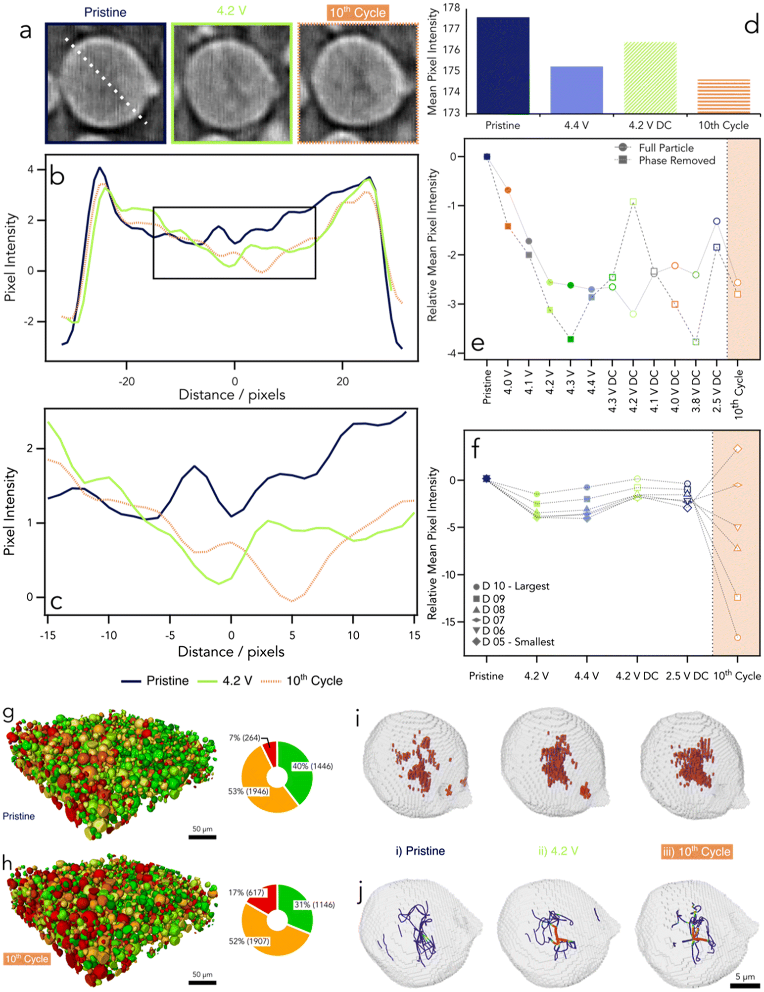 | ||
| Fig. 4 (a) Ortho slices of a particle at pristine (blue), 4.2 V (green), and 10th cycle (orange). (b) Line plot of pixel intensities from each ortho slice in (a), along the dotted white lines as shown. (c) Zoomed in line plot from (b). (d) Mean pixel intensity from deciles 5–10 at the states defined. The particle shown is 50 pixels in diameter, approximately 16.3 μm. (e) Relative mean pixel intensity plot (including the 10th cycle in orange) with respect to particle's pristine condition for the full particle (circles) and the phase-removed portion of the particles (squares) as shown in Fig. 2b. (f) Relative mean pixel intensity plots as in part (e), split into deciles. Values are presented as unit per volume (RMPI mm−3). (g and h) Absolute damage factor rendering of a RoI from the electrode at pristine (g) and 10 cycles (h) with equivalent pie chart of particle condition to the right. (i) Surface rendering of particle in (a) with voxels associated with cracks in red. (j) Skeletonised view of particle crack, with colour representing path thickness, thicker paths are coloured in red. All XCT after the 10th cycle was acquired at 2.5 V (discharged). | ||
After 10 cycles, mean pixel intensity reduction is apparent in both full particles and phase-ring-removed analyses (Fig. 4e). Cracking at low voltage (2.5 V) after ageing resembles that at high voltage in the first cycle, suggesting that post-ageing high-voltage states could induce further damage. Alternatively, high-voltage first-cycle cracking may establish steady-state cracks persisting across charge cycles. Larger particles in the top decile (D10) exhibit the lowest relative mean pixel intensity, consistent with their vulnerability to repeated cycling (Fig. 4f). Intriguingly, deciles 5 and 6 show increased pixel intensity, possibly due to a significant phase-enhanced peripheral region affecting observed damage or differing edge versus centre behaviour. Edge regions, characterized by aligned crystallites, are less damaged at low voltages after ageing. Damage factor analysis reveals a shift in particle damage states. Initially, 40% of particles are minimally damaged (53% moderately, 7% highly damaged). After 10 cycles, highly damaged particles increase to 17% (+10 percentage points), minimally damaged particles drop to 31% (−9 percentage points), while moderately damaged particles remain stable, likely transitioning between states.
Segmentation analysis (Fig. 4i) enables skeletonization of crack paths, simplifying the visualization of cracking directions (Fig. 4j). In the pristine particle, a central region of low-attenuation pixels indicates small defects and potential nucleation points for cracks. At 4.2 V during the first cycle, low-attenuation voxels increase and concentrate near the particle's centre, consistent with electrochemically induced cracking.5 After cycling, these voxels further increase and remain concentrated at the centre. The skeletonized pristine particle reveals small, central crack paths without significant thickness. At 4.2 V, cracks form a large central void with smaller branching paths. Two prominent perpendicular cords, highlighted in red (indicating thicker paths), dominate the central region. Post-cycling, these structures persist, with additional smaller offshoots emanating from inherent weak points. Despite the resolution limitations of this technique, the analysis suggests that initial defects and early-cycle cracks act as nucleation points for further cracking, often forming persistent main structures. After discharge, primary particles appear to fail at reconnecting, leaving grain boundaries as recurring weak points. Higher-resolution imaging is needed to confirm these findings.
3. Conclusions
The examination of crack formation, propagation, and reduction, whilst employing a commercially relevant pouch cell, signifies an advancement in the understanding of NMC811 fracture behaviour. Using our grey level analysis algorithm for fracture detection has introduced a high level of statistical robustness, validating the understanding of fracture behaviour previously divulged during high resolution, small field of view imaging,5 where here we have now quantified the fracturing in 7000+ particles, orders of magnitude greater than previously seen. This approach has unveiled the existence of non-linear cracking phenomena with respect to increasing potential, and the existence of cracking at notably low voltage levels, exemplified by instances at 4.0 V and 4.1 V during charge, and a notable amount of cracking even during discharge to 3.8 V. We see that on average there is no significant increase in the cracking between 4.2 and 4.4 V; however, literature has routinely showed that charging to a higher cut off voltage will reduce the lifetime of the cell. Thus, we also suggest that the degradation incurred at voltages higher than 4.2 V is a direct result of electrochemical reactions with the electrolyte and oxygen loss, and not inherent to cracking itself (from increased changes in crystal lattice parameters with increased upper cut off voltages).36 If the observed increase in capacity fade at higher voltages was primarily due to cracking, we would see a significant difference in cracking between 4.2 V and 4.4 V, not seen in this work.Furthermore, the confirmation of crack closing phenomena upon discharge introduces an interesting feature that has been hypothesized previously, suggesting the involvement of intricate primary particle mechanisms that could be investigated in the future during additional experimentation, where the interface between two particles at a reformed boundary is assessed. We also present, for the first time, a particle-by-particle analysis of damage and the complicated and often non-typical trajectories that are likely to be seen from particles. In addition to the cracking in the initial cycle, we were able to track the progression of the same particles after a number of cycles and can see that the cumulative effect of volume expansion and contraction on the particles over many cycles contributes to damage in the particle structure, more than charging high voltages alone (evidenced by lack of increased damage observed on first cycle charging beyond 4.2 V). This report leads to the possible exploration into further ageing and/or particles that are highly damaged before cycling (due to extensive levels of calendaring), uncovering the intricate evolution of crack behaviour and the interplay of high damage in the overall cracking process. This examination of the connection between mechanical and electrochemical stimuli in crack formation presents interesting future prospects for the approaches developed here. Whilst the use of synchrotron X-rays significantly reduced the acquisition time for this data, this technique has the potential to be employed in lab based XCT microscopes and thus is a facile solution for crack analysis progressing into commercial environments.
4. Materials and methods
4.1. Electrode preparation
Lithium nickel manganese cobalt oxide (NMC811, NEI Corp.) positive Li-ion electrode samples of areal capacity 2.2 mA h cm−2 was secured to a Petri dish using Kapton® tape before being fixed to the translation table of a laser micro machining instrument (A Series, Oxford Lasers Ltd) containing a 352 nm laser with a spot size of ∼40 μm. The laser was programmed to mill a series of lines at 2 mm s−1. The resultant electrode was cut to 15 × 20 mm (w × h) with a protrusion of 500 × 250 μm (w × h) from the top of the main electrode body. This area is used to image the electrode with limited FoV techniques and will be referred to as the tab. Additionally an area of 5 mm × 10 mm was milled into the opposite side of the electrode to allow for ultra-sonic welding of an aluminium terminal to the electrode's bare current collector.4.2. Pouch cell assembly
The cell contained a NMC811 electrode, as described above, and was assembled into a single layered pouch cell against a lithium counter electrode. The laser-cut electrode was ultra-sonically welded to a positive aluminium terminal (MTI corporation) before being heat sealed between the top side of two triple layered aluminium pouch cell material and then dried for 24 hours at 80 °C in a glass drying oven (B-585, BUCHI Ltd) with a ceramic reinforced tri-layered polyolefin separator (Celgard 2325, Celgard, LLC.) membrane and a nickel negative electrode terminal (MTI Corp.). Once dried, the pouch was transferred to an argon filled glove box to have the lithium counter electrode (Goodfellas) placed under the nickel terminal, before sealing two sides of the pouch using a vacuum sealing machine within the glove box. An excess (200 mL) of 1.0 M lithium hexafluorophosphate in ethylene carbonate and ethyl methyl carbonate with 2% by weight of vinylene carbonate additive (1.0 M LiPF6 in EC![[thin space (1/6-em)]](https://www.rsc.org/images/entities/char_2009.gif) :EMC (3:7 v/v) + 2% VC, Soulbrain MI), was added before sealing the last edge of the pouch. The pouch cell was left for 24 h to allow the electrolyte to wet the electrodes properly, some slight massaging of the cell was required during this time to assist with the electrolyte distribution. See Fig. S6 in the ESI† for pouch cell architecture.
:EMC (3:7 v/v) + 2% VC, Soulbrain MI), was added before sealing the last edge of the pouch. The pouch cell was left for 24 h to allow the electrolyte to wet the electrodes properly, some slight massaging of the cell was required during this time to assist with the electrolyte distribution. See Fig. S6 in the ESI† for pouch cell architecture.
4.3. Electrochemical control
The theoretical capacity value for the cell was calculated based on the area of the electrode main body (30 mm2) and the areal loading of the NMC811 electrode used, assuming the tab contribution was negligible to the overall total capacity. For the cell which contained 2.2 mA h cm−2 electrode the theoretical capacity calculated was 6.4 mA h. A low-current potentiostat (SP-300, Bio-logic SAS) was used and a constant-current constant-voltage (CC-CV) charge protocol was employed to charge each cell to the voltages as stated (3.8 V, 4.0 V, 4.1 V, 4.2 V, 4.3 V, 4.4 V vs. Li/Li+) before discharging to the same voltages. A C/3 rate based on the theoretical capacity calculated was used, and the cells were allowed to rest after the CV step and the current had dropped below the C/20 threshold. During this rest period tomograms were obtained. To age the cell, 10 further cycles we conducted at 1C to between 2.5 and 4.4 V without a constant voltage step. The cell was then imaged after the final discharge to 2.5 V. See Fig. S5 in the ESI† for full electrochemical data.4.4. X-ray computed tomography
A custom-made pouch cell holder made from Polyether Ether Ketone (PEEK) and an aluminium X-ray window was used to compress the pouch cell during the experiment. The holder allowed for repeated scanning of the same region of the electrode without removing the cell between tomographs. X-ray computed tomography was conducted at Diamond Light Source (DLS), Didcot, on the I13-2 Manchester Imaging beamline.49 Connections within the holder allowed for electrochemical control so the cell could be charged to specific voltages between 3.0–4.4 V (vs. Li/Li+), and images were acquired during open circuit voltage (OCV) after a voltage hold until the current had fallen to 10% of the charging current. A pco.edge 5.5 scintillator-coupled detector with pixel size of 6.5 × 6.5 μm was used in addition to a 10× objective lens giving an effective pixel size of 325 nm and FoV of 0.83 × 0.70 mm. 3000 projects were acquired for each tomography between 0–180 degrees at 0.8 seconds exposure. A pink beam at ∼25 keV was used for each sample.4.5. Image processing
The projections acquired during the experiment were processed and reconstructed into tomograms using Savu data pipelines at the I13-2 beamline at DLS.50,51 Projections were processed using the ring removal algorithm from Vo et al.,52 before rapid reconstruction with TomoPy's GridRec algorithm using the cluster computing resources available at DLS.53 Limited angles (3°–177°) reconstruction was required as the transmission of X-rays at extreme angles, and through the pouch cell holder, lead to streaking artifacts that lowered the quality of the reconstruction.The overarching aim of this data workflow was to be able to track particles across multiple tomograms acquired at different states-of-charge (SoC). This allowed us to track changes in grey level within these particles. The data processing pipeline is shown schematically in Fig. S3 in the ESI.† The data processing was performed with python scripts which allowed for a well-documented, repeatable, and modifiable workflow using open-source software. Rendering and visualisation tasks were carried out in Avizo (V2020.2, Thermo-Fisher Scientific).
The first step was to crop the tomograms to include the region-of-interest only, in this case the electrode tab. Next, we registered the tomograms onto each other. This ensured that the same co-ordinates in each tomogram represented the same points in real space. Registration was performed using SimpleITK.54 The registered tomograms were then converted to 8-bit, smoothed using a non-local means filter, and then segmented into binary images (particles/background) using a threshold. Morphological binary erosion and dilation was used to remove small binary ‘islands’ and ‘holes’ from the segmentation.
An instance or labels segmentation was then carried out. This separated the particles in the image and assigned a unique 16-bit label to each particle instance. In this case it was critical that the same label was assigned to corresponding particles in each tomogram so that they could be tracked across different SoC. Instance segmentation of particles was performed using the watershed segmentation method from scikit-image on a smoothed distance map of the binary segmentation.55 A set of seeds were created at the centre of each particle with the 16-bit label value assigned to each particle being assigned to its corresponding seed. These seeds were then used to label the particle instances in the succeeding tomogram, thereby enforcing the same labels across all the tomograms (at different SoC). This method relied on good registration between tomograms and minimal particle movement.
4.6. Data analysis
We used the instance segmentations and the accompanying un-smoothed 8-bit tomograms to extract characteristics of each particle. Query-able tabular data frames were populated with these characteristics on a particle-by-particle basis where each particle was indexed by its label in the instance segmentation. The characteristics included volume, surface area, sphericity, mean grey level, maximum grey level, minimum grey level, centroid co-ordinates, and other characteristics that where indicative of cracking in the particles. For each particle we also included an 8-bit grey level image of the particle in a bounding box and a distance transform image of the particle in a bounding box. These images allowed us to quickly calculate other bespoke particle characteristics by querying the table. These tables were calculated by our grey level analysis algorithm, which was able to analyse ∼84000 particles (7000 particles × 12 SoC) in minutes.
Such tables were calculated for each tomogram (thus for each SoC). When comparing between tables it was important to make sure that comparisons were made between identical sets of particles. To achieve this an inner join of each table to the pristine SoC table was performed on the particle index column. This dropped any rows that couldn't be tracked through all SoC. Additionally, any particles that shared an edge with particles that were dropped during this inner join operation were also dropped from the tables. This was because there was a tendency for neighbouring particle instances to ‘absorb’ the voxels previously labelled as another particle at a different SoC if an edge was shared between the particles. Finally, any particles that overlapped with the edge of the image are removed as these were likely to be partial particle volumes. These steps filtered the dataset from ∼10000 particles to ∼7600 particles.
We developed a range of functions that track grey level change in particles across various SoC by querying the tables. For example, we were able to track the change in mean grey level in particles across different SoC. We found that the phase enhanced region at the edge of particles observed different behaviour to the particle centres. We therefore created image masks from distance transform images of the particle so that these regions could be considered separately by applying the mask to the corresponding grey level image. Additionally, the grey level in radial layers can be analysed by developing a method analogous to Wade et al.30 Descriptions of these functions and how they were applied to the dataset is described in the ESI,† see Jones et al. for full details on the GRAPES python toolkit, GREAT2 algorithm, and associated GUI.29
Author contributions
HP, AL, HR, and CT performed synchrotron tomography. MJ developed the grey level analysis algorithm, which built on the algorithm developed by TH and AW. MJ and AW performed grey level analysis algorithm computation. MJ, HP, and AW carried out data analysis. RZ, SM, and CR were beamline scientists who assisted with planning and carrying out the experiments, PS and RJ supervised throughout. Initial manuscript written by HP, MJ, and RJ. All authors contributed to manuscript editing.Data availability
All tomographic data can be found for open access usage at https://doi.org/10.5522/04/25102538 under CC by 4.0 licence.Conflicts of interest
The authors declare no competing interests.Acknowledgements
This work was carried out with funding from the Faraday Institution (faraday.ac.uk; EP/S003053/1), grant numbers, FIRG060 and FIRG066; and the EPSRC grant EP/M014045/1. In addition, PhD funding for HP and AW by the Faraday Institution is also acknowledged: EPSRC training grant number EP/S514901/1. PRS was supported by the Department of Science, Innovation and Technology (DSIT) and the Royal Academy of Engineering under the Chair in Emerging Technologies programme (CiET1718/59). RJ, PRS and MPJ acknowledge Innovate UK for funding via the BATSEED Project (grant number: 10044823). This work was carried out with beamtime from Diamond Light Source, Didcot, on beamline I13-2 (Manchester Imaging Beamline) under proposal MG28650-1.References
- A. M. Boyce, E. Martínez-Pañeda, A. Wade, Y. S. Zhang, J. J. Bailey, T. M. M. Heenan, D. J. L. Brett and P. R. Shearing, J. Power Sources, 2022, 526, 231119 CrossRef CAS.
- T. Li, X.-Z. Yuan, L. Zhang, D. Song, K. Shi and C. Bock, Electrochem. Energy Rev., 2020, 3, 43–80 CrossRef.
- H. Wu, C. Qin, K. Wang, X. Han, M. Sui and P. Yan, J. Power Sources, 2021, 503, 230066 CrossRef CAS.
- A. Wade, A. V. Llewellyn, T. M. M. Heenan, C. Tan, D. J. L. Brett, R. Jervis and P. R. Shearing, J. Electrochem. Soc., 2023, 170, 070513 CrossRef CAS.
- H. C. W. Parks, A. M. Boyce, A. Wade, T. M. Heenan, C. Tan, E. Martínez-Pañeda, P. Shearing, D. Brett and R. Jervis, J. Mater. Chem. A, 2023, 11, 21322–21332 RSC.
- F. Schipper, E. M. Erickson, C. Erk, J.-Y. Shin, F. F. Chesneau and D. Aurbach, J. Electrochem. Soc., 2016, 164, A6220 CrossRef.
- C. Xu, K. Märker, J. Lee, A. Mahadevegowda, P. J. Reeves, S. J. Day, M. F. Groh, S. P. Emge, C. Ducati and B. L. Mehdi, et al. , Nat. Mater., 2021, 20, 84–92 CrossRef CAS PubMed.
- R. Jung, M. Metzger, F. Maglia, C. Stinner and H. A. Gasteiger, J. Electrochem. Soc., 2017, 164, A1361 CrossRef CAS.
- D. J. Xiong, L. D. Ellis, J. Li, H. Li, T. Hynes, J. P. Allen, J. Xia, D. S. Hall, I. G. Hill and J. R. Dahn, J. Electrochem. Soc., 2017, 164, A3025 CrossRef CAS.
- G. J. Páez Fajardo, E. Fiamegkou, J. A. Gott, H. Wang, I. Temprano, I. D. Seymour, M. J. W. Ogley, A. S. Menon, I. E. L. Stephens, M. Ans, T.-L. Lee, P. K. Thakur, W. M. Dose, M. F. L. De Volder, C. P. Grey and L. F. J. Piper, ACS Energy Lett., 2023, 5025–5031 CrossRef.
- Z. Xu, M. M. Rahman, L. Mu, Y. Liu and F. Lin, J. Mater. Chem. A, 2018, 6, 21859–21884 RSC.
- P. Yan, J. Zheng, M. Gu, J. Xiao, J.-G. Zhang and C.-M. Wang, Nat. Commun., 2017, 8, 1–9 CrossRef PubMed.
- H. Kim, M. G. Kim, H. Y. Jeong, H. Nam and J. Cho, Nano Lett., 2015, 15, 2111–2119 CrossRef CAS PubMed.
- X. Lu, A. Bertei, D. P. Finegan, C. Tan, S. R. Daemi, J. S. Weaving, K. B. O’Regan, T. M. M. Heenan, G. Hinds, E. Kendrick, D. J. L. Brett and P. R. Shearing, Nat. Commun., 2020, 11, 2079 CrossRef CAS PubMed.
- S. R. Daemi, C. Tan, T. G. Tranter, T. M. M. Heenan, A. Wade, L. Salinas-Farran, A. V. Llewellyn, X. Lu, A. Matruglio, D. J. L. Brett, R. Jervis and P. R. Shearing, Small Methods, 2022, 6, 2200887 CrossRef CAS PubMed.
- F. L. E. Usseglio-Viretta and K. Smith, ECS Trans., 2017, 77, 1095 CrossRef CAS.
- Z. Su, E. Decencière, T.-T. Nguyen, K. El-Amiry, V. De Andrade, A. A. Franco and A. Demortière, npj Comput. Mater., 2022, 8, 30 CrossRef.
- T. M. M. Heenan, A. V. Llewellyn, A. S. Leach, M. D. R. Kok, C. Tan, R. Jervis, D. J. L. Brett and P. R. Shearing, Adv. Sci., 2020, 2000362 CrossRef CAS PubMed.
- T. M. M. Heenan, A. Wade, C. Tan, J. E. Parker, D. Matras, A. S. Leach, J. B. Robinson, A. Llewellyn, A. Dimitrijevic and R. Jervis, et al. , Adv. Energy Mater., 2020, 10, 2002655 CrossRef CAS.
- C. Rahe, S. T. Kelly, M. N. Rad, D. U. Sauer, J. Mayer and E. Figgemeier, J. Power Sources, 2019, 433, 126631 CrossRef CAS.
- R. Xu, Y. Yang, F. Yin, P. Liu, P. Cloetens, Y. Liu, F. Lin and K. Zhao, J. Mech. Phys. Solids, 2019, 129, 160–183 CrossRef CAS.
- Y. Zhang, Z. Yang and C. Tian, J. Mater. Chem. A, 2019, 23628–23661 RSC.
- S. S. Shishvan, N. A. Fleck, R. M. McMeeking and V. S. Deshpande, J. Power Sources, 2023, 588, 233745 CrossRef CAS.
- K. Ishidzu, Y. Oka and T. Nakamura, Solid State Ionics, 2016, 288, 176–179 CrossRef CAS.
- S. Oswald, M. Bock and H. A. Gasteiger, J. Electrochem. Soc., 2023, 170, 090505 CrossRef CAS.
- A. V. Llewellyn, A. Matruglio, D. J. L. Brett, R. Jervis and P. R. Shearing, Condens. Matter, 2020, 5, 75 CrossRef CAS.
- J. Le Houx and D. Kramer, Energy Rep., 2021, 7, 9–14 CrossRef.
- X. Cheng, Y. Li, T. Cao, R. Wu, M. Wang, H. Liu, X. Liu, J. Lu and Y. Zhang, ACS Energy Lett., 2021, 6, 1703–1710 CrossRef CAS.
- M. Jones, H. Parks, A. Llewellyn, H. Reid, C. Tan, A. Wade, T. Heenan, F. Iacoviello, S. Marathe and P. Shearing.
- A. Wade, T. M. M. Heenan, M. Kok, T. Tranter, A. Leach, C. Tan, R. Jervis, D. J. L. Brett and P. R. Shearing, npj Mater. Degrad., 2022, 6, 1–13 CrossRef.
- D. J. Goodenough, K. E. Weaver, H. Costaridou, H. Eerdmans and P. Huysmans, Comput. Radiol., 1986, 10, 87–98 CrossRef CAS PubMed.
- T. M. M. Heenan, C. Tan, A. J. Wade, R. Jervis, D. J. L. Brett and P. R. Shearing, Mater. Des., 2020, 191, 108585 CrossRef CAS.
- S. C. Mayo, A. W. Stevenson and S. W. Wilkins, Materials, 2012, 5, 937–965 CrossRef CAS PubMed.
- G. R. Davis and J. C. Elliott, Mater. Sci. Technol., 2006, 22, 1011–1018 CrossRef CAS.
- S. Lee, L. Su, A. Mesnier, Z. Cui and A. Manthiram, Joule, 2023, 7, 2430–2443 CrossRef CAS.
- W. M. Dose, J. K. Morzy, A. Mahadevegowda, C. Ducati, C. P. Grey and M. F. L. De Volder, J. Mater. Chem. A, 2021, 9, 23582–23596 RSC.
- J. S. Edge, S. O'Kane, R. Prosser, N. D. Kirkaldy, A. N. Patel, A. Hales, A. Ghosh, W. Ai, J. Chen and J. Yang, et al. , Phys. Chem. Chem. Phys., 2021, 23, 8200–8221 RSC.
- R. Hausbrand, G. Cherkashinin, H. Ehrenberg, M. Gröting, K. Albe, C. Hess and W. Jaegermann, Mater. Sci. Eng., B, 2015, 192, 3–25 CrossRef CAS.
- K. Märker, P. J. Reeves, C. Xu, K. J. Griffith and C. P. Grey, Chem. Mater., 2019, 31, 2545–2554 CrossRef.
- A. S. Leach, A. V. Llewellyn, C. Xu, C. Tan, T. M. M. Heenan, A. Dimitrijevic, K. Kleiner, C. P. Grey, D. J. L. Brett and C. C. Tang, et al. , Front. Chem. Eng., 2022, 14, 794194 CrossRef.
- T.-T. Nguyen, J. Xu, Z. Su, V. De Andrade, B. Delobel, C. Delacourt and A. Demortière, arXiv, 2023, 1, 2307 Search PubMed preprint.
- C. Tan, A. S. Leach, T. M. M. Heenan, H. Parks, R. Jervis, J. N. Weker, D. J. L. Brett and P. R. Shearing, Cell Rep. Phys. Sci., 2021, 2, 1–22 Search PubMed.
- C. Xu, A. J. Merryweather, S. S. Pandurangi, Z. Lun, D. S. Hall, V. S. Deshpande, N. A. Fleck, C. Schnedermann, A. Rao and C. P. Grey, Joule, 2022, 6, 2535–2546 CrossRef CAS.
- M. Kim, H. Kim, I. Kim, B. Chang and J. W. Choi, Proc. Natl. Acad. Sci. U. S. A., 2022, 119, e2211436119 CrossRef CAS PubMed.
- J.-M. Lim, T. Hwang, D. Kim, M.-S. Park, K. Cho and M. Cho, Sci. Rep., 2017, 7, 39669 CrossRef CAS PubMed.
- L. An, J. E. N. Swallow, P. Cong, R. Zhang, A. D. Poletayev, E. Björklund, P. N. Didwal, M. W. Fraser, L. A. H. Jones, C. M. E. Phelan, N. Ramesh, G. Harris, C. J. Sahle, P. Ferrer, D. C. Grinter, P. Bencok, S. Hayama, M. S. Islam, R. House, P. D. Nellist, R. J. Green, R. J. Nicholls and R. S. Weatherup, Energy Environ. Sci., 2024, 17, 8379–8391 RSC.
- P.-C. Tsai, B. Wen, M. Wolfman, M.-J. Choe, M. S. Pan, L. Su, K. Thornton, J. Cabana and Y.-M. Chiang, Energy Environ. Sci., 2018, 11, 860–871 RSC.
- J. H. Kim, H. H. Ryu, S. J. Kim, C. S. Yoon and Y. K. Sun, ACS Appl. Mater. Interfaces, 2019, 11, 30936–30942 CrossRef CAS PubMed.
- C. Rau, U. Wagner, Z. Pešić and A. De Fanis, Phys. Status Solidi A, 2011, 208, 2522–2525 CrossRef CAS.
- A. J. Bodey and C. Rau, J. Phys.: Conf. Ser., 2017, 849, 012038 CrossRef.
- R. C. Atwood, A. J. Bodey, S. W. T. Price, M. Basham and M. Drakopoulos, Philos. Trans. R. Soc., A, 2015, 373, 20140398 CrossRef PubMed.
- N. T. Vo, R. C. Atwood and M. Drakopoulos, Opt. Express, 2018, 26, 28396–28412 CrossRef PubMed.
- D. Gürsoy, F. De Carlo, X. Xiao and C. Jacobsen, J. Synchrotron Radiat., 2014, 21, 1188–1193 CrossRef PubMed.
- B. C. Lowekamp, D. T. Chen, L. Ibáñez and D. Blezek, Front. Neuroinf., 2013, 7, 45 Search PubMed.
- S. Van der Walt, J. L. Schönberger, J. Nunez-Iglesias, F. Boulogne, J. D. Warner, N. Yager, E. Gouillart and T. Yu, PeerJ, 2014, 2, e453 CrossRef PubMed.
Footnote |
| † Electronic supplementary information (ESI) available. See DOI: https://doi.org/10.1039/d5eb00008d |
| This journal is © The Royal Society of Chemistry 2025 |