
 Open Access Article
 This Open Access Article is licensed under a Creative Commons Attribution-Non Commercial 3.0 Unported Licence
Sodium ion conductivities in Na2O–Sm2O3–SiO2 ceramics†
Abinaya
Sivakumaran
 a,
Vishnu
Surendran
a,
Shantel
Butler
d,
Samuel
Reid
b and
Venkataraman
Thangadurai
*ac
a,
Vishnu
Surendran
a,
Shantel
Butler
d,
Samuel
Reid
b and
Venkataraman
Thangadurai
*ac
aDepartment of Chemistry, University of Calgary, Calgary, AB T2N 1N4, Canada. E-mail: vthangad@ucalgary.ca; vt36@st-andrews.ac.uk
bGeometric Energy Corporation, 1400–3507 Ave SW, Calgary, Alberta T2P 3N9, Canada
cSchool of Chemistry, University of St Andrews, KY16 9AJ, UK
dElektra Industries, 2700-225 6 Ave SW, Calgary, AB T2P 1N2, Canada
First published on 30th January 2025
Abstract
Ceramic solid electrolytes are promising candidates for advanced solid-state batteries (SSBs) owing to their good ionic conductivity, wide electrochemical stability window, excellent thermal stability and enhanced safety compared to organic liquid electrolytes. In this study, we developed a series of sodium samarium silicates via a conventional solid-state approach using NaNO3, Sm2O3, and SiO2 precursor powders. By incorporating varying amounts of NaNO3, we optimized the ionic conductivity influenced by sodium, and a higher Na content increased the ionic conductivity of silicates to an extent. Among the compositions prepared, N5Sm exhibited the lowest grain boundary resistance and achieved the highest total ionic conductivity of 1.33 × 10⁻³ S cm−1 at 25 °C after being sintered at 975 °C. The best ion conducting composition demonstrated an electronic conductivity of 9.47 × 10⁻¹⁰ S cm−1, seven orders of magnitude lower than the ionic conductivity. These silicates also showed exceptional electrochemical stability up to 9 V, making them highly suitable for advanced high-voltage sodium battery applications. These findings underscore the potential of silicate electrolytes in developing next-generation batteries.
Broader contextSolid-state batteries (SSBs) are promising next-generation energy storage technologies owing to their enhanced safety and high energy densities, which make them well-suited to meet global energy demands. Achieving optimal performance in SSBs requires selecting solid electrolytes with high ionic conductivity, good thermal and mechanical stability, low sintering temperature, and strong electrode compatibility. In response to these challenges, we have developed sodium silicate-based ceramics with lower sintering temperatures compared to other well-known solid electrolytes for sodium-ion batteries. Our study focuses on the synthesis of sodium silicates and examines the influence of sodium content on phase formation and ionic conductivity. The results demonstrate that this silicate electrolyte offers superior ionic conductivity, negligible electronic conductivity, and a wide electrochemical stability window, making it a strong candidate as a solid electrolyte for solid-state sodium battery applications. |
1 Introduction
Solid-state sodium batteries (SSSBs) have emerged as a promising and sustainable energy storage alternative to conventional lithium-ion batteries (LIBs), mainly offering a safe and cost-effective technology for grid-storage applications.1–3 These batteries, featuring solid electrolytes that serve as Na+ ion conductors and separators, offer significant advantages, including better ionic conductivity, enhanced safety, high thermal stability, and a wide electrochemical stability window. In parallel to SSSBs, room-temperature lithium/sodium–sulfur batteries (Li/Na–S) are gaining attention as next-generation alternative battery technologies due to the low cost of sulfur and high theoretical energy density of batteries, Li–S (2600 Wh kg−1) and Na–S (1274 Wh kg−1).4–8Among the various Na+ ion conducting ceramics studied, Na-β-alumina and sodium superionic conductors (NASICON) (Na3Zr2PSi2O12) are widely explored and utilized in high-temperature Na–S and room-temperature sodium-ion batteries (SIBs).9–11 Beta alumina is the earliest fast Na+ ion conductor with an ionic conductivity of 0.2–0.4 S cm−1 at 300 °C. However, unacceptable mechanical strength and undesirable side reactions limit its applications in room temperature (RT) batteries.12,13 NASICON materials have an open 3D framework structure with an enhanced ionic conductivity of 10−3 S cm−1 at RT with appropriate substitutions/elemental dopings.14,15 However, considerable grain boundary resistance and harsh synthesis conditions hinder the application of NASICONs.16 In exploring suitable Na+ conducting ceramics with low sintering temperatures and high ionic conductivity, Maksimov et al. discovered Na5YSi4O12 sodium silicate materials in 1973.17 Shannon et al. synthesized a series of sodium silicates, identifying Na5SmSi4O12 as highly conductive, achieving a Na+ ion conductivity of 3 × 10⁻² S cm−1 at 300 °C.18 During the synthesis of Na5MSi4O12 (N5) (M = rare-earth elements) ceramics, the formation of Na3MSi3O9 (N3) and Na9MSi6O18 (N9) was observed.18,19 Unlike the N5 phase, the N3 and N9 phases are poor ionic conductors.20
Further research on sodium samarium silicates was conducted by Okura et al. in 1996, in which Na5SmSi4O12 glass-ceramics were synthesized by a sol–gel method and particularly Na3.75Sm0.75Si3O9 achieved the highest conductivity of 4.82 × 10⁻² S cm−1 at 300 °C.21 Followed by this, they have developed a series of Na5SmSi4O12 glass-ceramics by investigating the substitution of Ge and Te on Si sites,22 He3+ implantation,19 and Al, Ga and P-based silicates (Na2O–Sm2O3–X2O3–P2O5–SiO2) (X = Al, Ga).23 A detailed study on the crystallization, microstructure and ion conduction of Na3.9Sm0.6P0.3Si2.7O9 was reported.24 Recently, these materials have gained renewed attention due to their stable structures, which offers further chemical modification, achieving good ionic conductivity and lower sintering temperature.25–31 A detailed review of the crystal structure, synthesis methods and ionic conduction mechanism of sodium silicates was recently published.32 The latest advancement of Na5SmSi4O12 by Yi et al. utilized a grain boundary-modified strategy to generate in situ amorphous grains by tuning the chemical composition.33 This approach has obtained the highest sodium ion conductivity of 5.61 mS cm−1 at room temperature.
In this study, we aim to further develop sodium samarium silicate (Na3SmSi3O9) ceramics with excess Na and investigate the effect of excess Na on ionic conductivity. Our approach utilizes a conventional solid-state method with a significantly lower sintering temperature of 975 °C. Increasing the excess Na in the composition leads to a complete phase transformation, as evident from the PXRD and ion conduction results. Among the six compositions investigated in this study, Na5SmSi4O12 (N5Sm) showed the highest ionic conductivity of 1.33 × 10⁻³ S cm−1 at room temperature. The resulting samarium silicates also demonstrate low electronic conductivity and a wide electrochemical stability window of up to 9 V vs. (Na+, Na). These characteristics make samarium silicates an excellent candidate for solid electrolytes in next-generation solid state sodium metal batteries.
2 Experimental section
2.1 Synthesis
The synthesis of sodium samarium silicate follows a conventional solid-state method. A stoichiometric amount of all precursors including sodium nitrate (NaNO3) (ACS reagent, ≥99.0%), samarium oxide (Sm2O3) (REacton™, 99.9% (REO)) (Thermo Scientific Chemicals) and silicon dioxide (SiO2) (∼99%, 0.5–10 μm, with approx. 80% between 1 and 5 μm) (Sigma-Aldrich) was used for the nominal composition, Na3SmSi3O9 (N3Sm). Four more compositions were developed using varying amounts (5–20%) of excess NaNO3 to compensate for Na volatilization during high-temperature sintering and to understand the effect of excess Na on ionic conductivity. The four samples were abbreviated as 5, 10, 15 and 20-N3Sm. Na5SmSi4O12-based samarium silicate composition was also attempted for phase formation and designated as the sixth composition, Na5SmSi4O12 (N5Sm). Before synthesizing all six compositions, Sm2O3 was preheated at 900 °C for 6 h to remove excess moisture.The precursor powders were then homogeneously mixed using a ball mill (Pulverisette, Fritsch, Germany) at 200 rpm for 6 h with 2-propanol. Following thorough mixing, the precursor powders underwent a calcination process at 900 °C for 6 h to remove nitrates from the starting materials. After calcination, the powders were ball milled again at 200 rpm for 12 h to ensure homogeneity. Subsequently, the powders were dried and pressed into pellets with a diameter of 13 mm using isostatic pressing and then sintered at 975 °C for 6 h in an alumina crucible covered with the mother powder to compensate for volatilization of Na. Before further testing, the sintered ceramic pellets were polished and annealed under N2 at 700 °C for 1 h to eliminate surface contaminants, including Na2CO3 and NaOH.
2.2 Materials characterization
The crystalline phases of all the silicates were characterized by Powder X-ray diffraction (PXRD) using a Bruker D8 advance diffractometer with Cu kα radiation (40 kV, 20 mA) in the 2θ range of 10–40°. The PXRD data for all compositions were collected at room temperature. The relative density of the ceramic pellets was calculated using an Archimedes density method using 2-propanol as a suspension medium. The cross-sectional morphology and microstructure of all compositions were examined using scanning electron microscopy (SEM), and the elemental composition for all samples was determined using energy dispersive X-ray spectroscopy (EDX) with the help of ThermoFisher Scientific Phenom G6 Pro.2.3 Electrochemical characterization
The ionic conductivity of the samples has been calculated by performing Electrochemical Impedance Spectroscopy (EIS) in the frequency range of 1 MHz–1 Hz at an amplitude of 100 mV using a Solartron 1260 impedance analyzer. All the ceramic pellets were coated with gold (Au) to serve as blocking electrodes before the impedance measurement. The temperature dependence of the ionic conductivity was measured from 25 to 150 °C. DC polarization measurement was carried out with the same Au-coated pellets to measure the electronic conductivity contribution of N5Sm by applying a constant voltage of 0.1 V at 25 °C.The electrochemical stability window was measured using cyclic voltammetry (CV) by scanning from −0.5 V to 9 V vs. Na at a scan rate of 3 mV s−1, with the solid electrolyte placed between Au and Na electrodes. Symmetric cells were assembled in a 2032 coin cell under an Ar-filled glovebox using sandwiched sodium foils on both sides of the best conducting solid electrolyte. Long-term Na plating/stripping tests were carried out on symmetric cells at a constant current density of 0.05 mA cm−2 for 150 h with 60 minutes per plate/strip. Hybrid batteries were made in a coin cell with sodium foil as an anode and silicate (solid electrolyte and a separator) with an NVP cathode. A small amount of liquid electrolyte, 10 μl, was added to the cathode side to improve wettability. 500 psi pressure was applied during the coin cell assembly of symmetric and hybrid batteries. The thickness of the solid electrolyte utilized in symmetric and hybrid batteries was 8 mm. The liquid electrolyte utilized for the battery was 1 M sodium perchlorate (NaClO4) in propylene carbonate![[thin space (1/6-em)]](https://www.rsc.org/images/entities/char_2009.gif) :fluoroethylene carbonate (PC:FEC) (95:05 wt%).
:fluoroethylene carbonate (PC:FEC) (95:05 wt%).
3 Results and discussion
3.1 Effect of excess NaNO3 on the phase formation
Sodium samarium silicates were synthesized via a solid-state approach and have a lower sintering temperature of 950–975 °C compared to other solid electrolytes such as Na-β-alumina (∼1600 °C), NASICON (1100–1200 °C), and sodium yttrium silicates (Na5YSi4O12) (1100 °C).34–36 The PXRD patterns for the compositions sintered at 975 °C for 6 h are shown in Fig. 1. The PXRD patterns match the reference patterns of # Na3SmSi3O9, # Na5SmSi4O12 and # Na9SmSi6O18. The peaks of N3Sm match the reference pattern of # Na3SmSi3O9. However, despite achieving an N3Sm phase, its ionic conductivity remains low even at elevated temperatures (∼200 °C). | ||
| Fig. 1 PXRD patterns, along with the reference patterns of Na3SmSi3O9, Na5SmSi4O12, and Na9SmSi6O18. The PXRD of N3Sm matches the reference patterns of Na3SmSi3O9 and it occurs to be phase-pure. Compositions 5–20% N3Sm and N5Sm match the reference patterns of Na5SmSi4O12. The N9 and unknown peaks are denoted by symbols: (♠) and (♦). | ||
Therefore, attempts have been made to add excess NaNO3 during the synthesis of N3Sm in order to enhance the Na+ ion movement in the crystal system. Specifically, 5–20% excess NaNO3 was added during the synthesis, resulting in four more compositions, as abbreviated in the Experimental section. The addition of various amounts of excess NaNO3 results in the complete conversion to Na5SmSi4O12 as a major phase, with an impure phase of Na9SmSi6O18 and an unknown peak around 18.7° as depicted in Fig. 1. This unknown peak is present mainly in 15 and 20-N3Sm. Even though the formed major phase is Na5SmSi4O12, all the peaks are shifted to the left (lower 2θ) compared to the reference. Adding excess Na increases the unit cell volume, possibly explaining the shift toward the left. According to the literature on Na excess in the NASICON structure,37 their DFT calculation shows that excess Na leads to a higher occupancy of Na atoms in the crystal structure, thereby increasing the unit cell volume. The attempted N3 phases with excess NaNO3 exhibit improved ionic conductivity at RT in contrast to the pure N3 phase without excess NaNO3, which is due to the formation of the dominant N5 phase, where the N5 phase is known as the highly conducting phase compared to N3/N9. Similar N3 and N9 impurity phases have been observed in other studies, and they are known to reduce the ionic conductivity of N5 ceramics.20,38,39 Since our attempt yielded a different phase than intended, we focused on synthesizing the pure phase of N5Sm itself using the stoichiometric proportions of precursors. The PXRD patterns of the synthesized N5Sm match with the reference pattern of # Na5SmSi4O12 with similar impurity peaks of N9 and an unknown peak at 18.8° are observed. The N9 impure phase can be eliminated through ball milling and re-sintering as well as by quenching.26,30
In conclusion, almost pure N3 phase was achieved in one of the six compositions prepared, while N5 formed in all other compositions along with additional impure phases. Based on our study, the pure phase of the highly conducting N5 phase without any impurities is not achieved. Further research and modification of the synthesis route are needed to achieve a phase pure Na5SmSi4O12 material.
3.2 Electrochemical impedance spectroscopy (EIS) results
The ionic conductivities and activation energies for all prepared silicates have been calculated using the following equations: | (1) |
 | (2) |
 | (3) |
 | ||
| Fig. 2 (a) EIS of (5–20)-N3Sm and N5Sm at RT, with N5Sm showing lower grain boundary resistance and 5-N3Sm exhibiting the highest grain boundary resistance, (b) Arrhenius plot of all five compositions collected from RT to 150 °C, and (c) frequency versus conductivity plot of silicates. Equivalent circuit fit is included in the inset of (a). (Due to low ionic conductivity, Arrhenius plot and dielectric studies were not included for N3Sm.) | ||
The frequency-dependent electrical properties of silicates at RT follow the Jonscher universal power law, which expresses the relationship between AC conductivity and frequency as given in the equation below:
| σω = σdc + Aωn | (4) |
3.3 Microstructure and elemental composition of silicates
Fig. S2† presents the cross-sectional SEM images of silicates sintered at 975 °C. The morphology of N3Sm shows numerous macropores, significantly contributing to its low ionic conductivity. The grains are visible inside these pores, indicating poor densification due to the noticeable gaps between them. These larger pores and gaps interrupt Na+ transport at grain and grain boundaries, markedly increasing the bulk and grain boundary resistance of the solid electrolytes. In contrast, 5–20 N3Sm silicates exhibit a dense morphology with well-connected grains and smaller irregular pores, approximately 2–3 μm in size. These small numbers of irregular pores observed in all four compositions also affect the density values. Two distinct compositions are present in the microstructure of all silicates prepared, indicated by white particles (smaller crystals) on the bulk dense microstructure. N5Sm shown in Fig. 3a, in particular, is denser with fewer pores than others, facilitating efficient Na+ conduction and improved ionic conductivity. Even the mixed phase is slightly reduced, as indicated by the reduction of white particles in the bulk structure, proving that phase formation and conductivity mechanisms correlate with the morphology of the developed silicates. This reduction in the number of pores can suppress sodium dendrite formation and enhance the mechanical strength of the ceramic, potentially improving the battery performance. The spot EDX analysis of the cross section for N5Sm is provided in Fig. 3b; the corresponding elemental atomic percentages are shown in Fig. 3c and d. The spot EDX patterns for the other five compositions are included in Fig. S3–S7.† Spot EDX on the bulk structure and the white particle (marked in Fig. 3b) was carried out to understand the ratio of elements such as Na, Si, Sm and O in the microstructure. Based on the ratio, all compositions showed mostly higher Sm and Na presence in the white particle, possibly due to the formation of a samarium and sodium rich phase compared to the bulk structure, which has been observed as unknown peaks in the phase analysis. This indicates the presence of a secondary phase in addition to the visual observation of white particles onto the bulk structure. The cross-section SEM with mapping of elements including Na, Sm, Si and O for N5Sm pellet is given in Fig. 4(a)–(e). From the mapping, all four elements are distributed all over the surface of the N5Sm silicate, where Sm presence is slightly higher in certain regions (white particles) compared to others. | ||
| Fig. 3 (a) Cross-sectional morphology of N5Sm, (b) spot EDX of the cross-section of N5Sm on (c) the bulk microstructure and (d) white particles. | ||
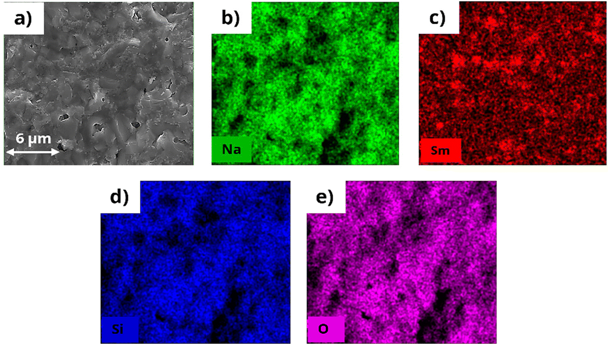 | ||
| Fig. 4 (a) Cross-section SEM of N5Sm pellet with (b)–(e) mapping of the desired elements present (Na, Sm, Si, and O). | ||
The Archimedes bulk density of silicates was measured using 2-propanol as the suspension medium and then computed using
 | (5) |
From Table S2,† comparing the density and ionic conductivity of silicates, the density increases slightly with the addition of excess Na, where 5-N3Sm has the lowest density, which starts to slightly increase from 10-N3Sm to 20-N3Sm, and N5Sm exhibits a higher density of 3.417 g cm−3 among the five compositions. In contrast, the ionic conductivity linearly increases by increasing the concentration of excess NaNO3 in the silicate compositions, from 5-N3Sm to 15-N3Sm, but after 15-N3Sm, the ionic conductivity decreases for 20-N3Sm. Among them, N5Sm showed the highest conductivity with higher density. N3Sm is not included since it showed a lower density of 2.738 g cm−3 with low ionic conductivity at 200 °C. Even though density is slightly higher for 20-N3Sm, the Na ion conduction is not as good as that of 15-N3Sm. This proves that the density alone cannot play a significant role in the movement of sodium ions in the solid electrolyte, which influences the ionic conductivity. Excess Na in the structure could have influenced the formation of more secondary phases that can block ionic pathways in 20-N3Sm compared to 15-N3Sm, as seen in phase analysis. Therefore, according to the compositions prepared, 15-N3Sm is the optimum excess Na needed for the silicate to facilitate high Na+ movement in the structure among 5, 10 and 20-N3Sm.
3.4 Electronic conductivity and electrochemical stability window of N5Sm
Electronic conductivity pertains to the mobility of electrons or holes within a material. This is an important parameter that can affect solid electrolyte performance. Ideally, solid electrolytes should be perfect electronic insulators, as any electronic conductivity can lead to self-discharge.44 A non-negligible electronic conductivity is a possible contributing factor for the internal growth of dendrites, where mobile Li+/Na+ ions are directly reduced to Li0/Na0 metal within the solid electrolyte bulk.45–47 The electronic conductivity, which is in the range of 10−10 to 10−12 S cm−1, is the upper limit threshold for a solid electrolyte to resist dendrite growth via bulk nucleation at a current density of 1 and 10 mA cm−2 proposed by Han et al.47Electronic conductivity is measured through DC polarization by applying a constant potential to the solid electrolyte coated with Au-blocking electrodes on both surfaces. Here, the Au/N5Sm/Au cell was polarized at a DC voltage of 0.1 V, as shown in Fig. 5a. The current response under DC polarization was recorded for 16 h to determine the steady-state current.
 | ||
| Fig. 5 (a) DC polarization current versus time curve using a two-blocking electrode cell, Au/N5Sm/Au at 0.1 V (RT) (initial and steady-state currents are represented in the curve, and the electronic conductivity value is determined from the steady-state current based on Ohm's law). (b) Electrochemical stability window of N5Sm using the cell configuration Na/N5Sm/Au at a scan rate of 3 mV s−1 (RT). The redox peak around 0 V represents the oxidation and reduction of sodium metal. | ||
A high current response is exhibited by applying a constant voltage, indicating the ionic contribution (Iin). As time progresses, the current decreases and eventually reaches a steady state (Iss), reflecting the polarized state of the solid electrolyte.48,49 The steady state current is contributed by the electron conduction. Using Ohm's law, σe = L/(S) × I/E, where σe is the electronic conductivity, L is the thickness of the solid electrolyte, S is the area of the solid electrolyte, E is the polarization voltage, and I is the steady state current obtained from the curve. Using the equation, the electronic conductivity was calculated to be 9.47 × 10⁻¹⁰ S cm−1, seven orders of magnitude lower than the respective ionic conductivity. This significantly lower electronic conductivity can reduce the self-discharge of batteries, enhance the Na+ transference number and help mitigate Na dendrite formation, making it advantageous for advanced solid-state batteries.
To enable high voltage output for SSSBs, coupling a sodium metal anode with a high voltage cathode requires a wide electrochemical stability window (0–5 V) for an ideal solid electrolyte. The electrochemical stability window of N5Sm was determined using cyclic voltammetry (CV) with the cell configuration Na||N5Sm||Au, where Au acts as the working electrode. CV was conducted at a scan rate of 3 mV S−1 over a voltage range from −0.5 to 9 V vs. Na. A redox peak around 0 V was observed, attributed to the reversible oxidation and reduction of sodium (plating and stripping on Au), as shown in Fig. 5b. No other reduction or oxidation peaks were detected up to 9 V, indicating that the N5Sm solid electrolyte possesses superior electrochemical stability. This makes it highly suitable for high-voltage cathodes for next-generation energy storage applications.
3.5 Wetting behaviour of molten sodium on silicate electrolytes
Proper wetting of alkali metals on the surface of solid electrolytes is crucial for improving the performance of solid-state batteries. The large surface energy difference between molten Na and solid electrolyte surface causes molten Na to appear as a bead with a large contact angle.50 For solid electrolytes like NASICON, a chemical reaction occurs between molten Na and the NASICON surface at 380 °C, which results in the partial reduction of the surface that improves the Na wettability.16,51 Some research has proven that annealing the solid electrolyte can remove the surface functional groups, thus enhancing Na wettability.50 Others have also demonstrated other strategies by developing alloying anodes to tune the surface energy, thereby improving lithiophilicity/sodiophilicity.52,53Here, to investigate the wetting behaviour of molten sodium metal on the surface of silicate electrolytes, we heated all six pellets to around 200 °C on a hot plate to remove the absorbed moisture or any other organic impurities. After cooling, sodium metal foils were placed on the cleaned surfaces and reheated to around 200 °C until the sodium melted. The wettability of molten sodium on the surface of six different compositions is shown in Fig. 6. The results indicate that almost all compositions exhibited poor wettability with molten sodium, as evidenced by the spherical shape of the sodium droplets. The contact angles of molten sodium on the first three compositions, including N3Sm, 5-N3Sm, and 10-N3Sm, were relatively large, exceeding 90°. The wettability is improved for the other three compositions, which are 15-N3Sm, 20-N3Sm, and N5Sm. N5Sm, in particular, demonstrates the best wettability of sodium among all others. Considering the improved Na ion conductivity and wettability of N5Sm among other compositions, long-term sodium plating/stripping stability tests were performed at a low current density of 0.05 mA cm−2 for 300 h (150 cycles) with a plating and stripping time of 60 minutes, as shown in Fig. 7. The cell showed a symmetric voltage plateau during plating and stripping, indicating uniform deposition of sodium on both sides of the solid electrolyte for 150 cycles. The flat voltage profile is also observed from the inset, which is shown at the start and end of the cycles. EIS before and after 300 h plating/stripping is included in Fig. S7,† where there is a negligible change in resistance before and after plating/stripping. Further research is needed to modify the interface to improve wettability, reduce interfacial resistance and increase the critical current density of silicates for high-energy density batteries.
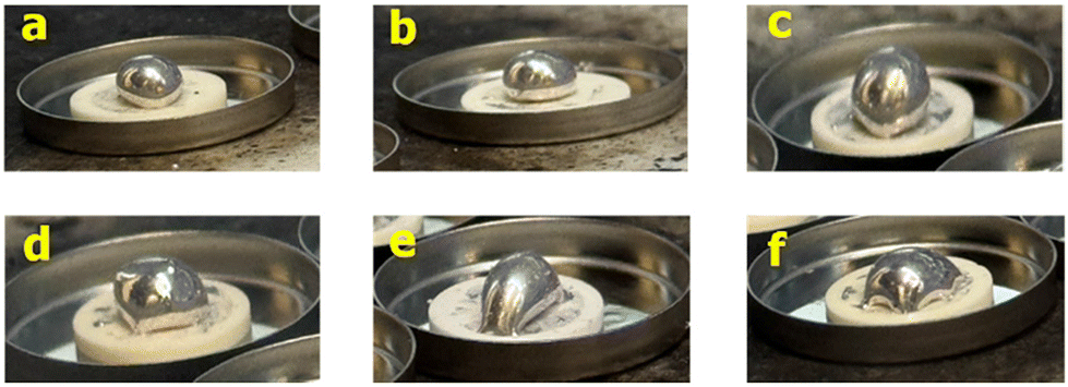 | ||
| Fig. 6 Optical images of the wettability of molten sodium on top of the annealed silicate surfaces: (a) N3Sm, (b) 5-N3Sm, (c) 10-N3Sm, (d) 15-N3Sm, (e) 20-N3Sm, and (f) N5Sm. | ||
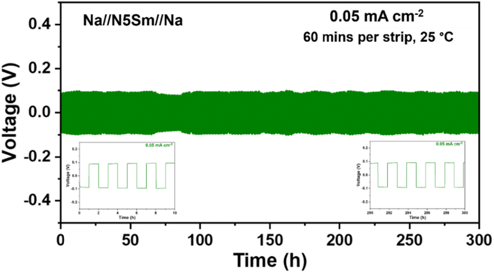 | ||
| Fig. 7 Long-term galvanostatic Na plating/stripping cycling profiles of Na//N5Sm//Na at a constant current density of 0.05 mA cm−2 for 300 h (60 minutes per strip). | ||
3.6 Hybrid battery performance
A full cell has been fabricated to validate the potential use of silicate as a separator and solid electrolyte. The hybrid battery utilizing N5Sm silicate solid electrolyte is paired with a sodium metal anode and the synthesized Na3V2(PO4)3 (NVP) cathode, followed by the synthesis procedure from previous work.54 The cathode loading is 1.28 mg cm−2 and its diameter is 10 mm. A small amount of liquid electrolyte, 1 M NaClO4 in PC:FEC (95:05%), is added on the cathode side to improve the wettability of the NVP cathode. The coin cell was assembled in an Ar-filled glovebox, and the galvanostatic charge–discharge tests were conducted at RT using a battery cycler. The voltage range was set between 2 and 4 V at a current rate of 0.1 C. As shown in Fig. 8, the flat voltage profile at 3.4 V can be ascribed to the Na (de)intercalation into the NVP structure. During the first cycle, the charging and discharging capacities are 75 and 73 mAh g−1. However, the capacity achieved is lower than the theoretical capacity of NVP (118 mA h g−1), whereas negligible capacity degradation is observed over 50 charge–discharge cycles.
 | ||
| Fig. 8 Galvanostatic charge–discharge curves between 2 and 4 V at a current rate of 0.1 C of a hybrid battery at RT using the configuration Na//N5Sm//LE//NVP (liquid electrolyte used: 1 M NaClO4 in PC:FEC (95:05%)). | ||
3.7 Comparison with other recent developments in silicate based sodium-ion conductors
The reports on sodium silicates developed in recent years (2019–present) are summarized in Table 1.25–31,33,40,55–58 Research works on sodium silicates have started to emerge since 2019, where all NASICON-type solid-state sodium-ion full cells have been developed by Sun et al., which utilize a Na3V2(PO4)2O2F cathode and Na3V2(PO4)3 anode, along with Na5YSi4O12 composite electrolyte.55 Notably, the sintering temperature for silicates is lower than that of other oxide electrolytes like β-alumina and NASICON. Among the silicates, Y3+-based materials exhibit the highest sintering temperature of 1100 °C, while Sm3+-based materials demonstrate the lowest at 950 °C, with other silicates falling within this range. Silicates also demonstrate a higher electrochemical stability window, making them promising candidates for next-generation batteries with high-voltage cathodes. For example, Na4.92Y0.92Zr0.08Si4O12 showed an impressive electrochemical stability window between −0.5 and 10 V.40 These silicates achieved higher critical current densities than other solid electrolytes without interfacial treatment. Na5YSi4O12, reported by Sun et al., went up to 2.2 mA cm−2 for sodium plating/stripping without any modification.26 The highest CCD of 3 mA cm−2 is achieved for the Na5YSi4O12 scaffold developed via an aqueous tape casting approach. Na5YSi4O12 is the most widely studied silicate, and recently, Gd- and Sm-based silicates have also been developed and achieved outstanding performance.30,31,33 Based on a recent study, Na5SmSi4O12 developed by Yi et al. showed a superior ionic conductivity of 5.61 mS cm−1 with an activation energy of 0.2 eV. Na2O–Sm2O3–SiO2 prepared in the current work has achieved an ionic conductivity of 1.33 mS cm−1 comparable with that of others with an electrochemical stability window up to 9 V. We have also achieved the lowest electronic conductivity of 9.47 × 10⁻¹⁰ S cm−1 for N5Sm compared to others. Further research has to be continued on these materials, which have excellent electrical and electrochemical properties and are suitable as solid electrolytes for SSSBs.| Composition | Sintering temperature (°C) | Ionic conductivity (S cm−1) (25 °C) | Activation energy (eV) | Electronic conductivity (S cm−1) (25 °C) | Electrochemical stability window (V) | Critical current density (mA cm−2) | Ref. |
|---|---|---|---|---|---|---|---|
| Na5YSi4O12 | 800 | 5.46 × 10⁻⁵ | 0.32 | — | — | — | 55 |
| Na5YSi4O12 | 1100 | 1.59 × 10⁻³ | 0.20 | 10−8 | 8 | 2.2 | 26 |
| Na5YSi4O12 (thin film) | 1100 | 1 × 10⁻³ | 0.30 | — | 8 | 2.2 | 27 |
| Na4.0Y0.6P0.2Si2.8O9 | 1100 | 3.7 × 10⁻² (300 °C) | 0.20 | — | — | — | 56 |
| Na5RSi4O12 (R = Y, Gd, and Sm) | 1050–1120 | 1.82 × 10⁻³ (20 °C) (Y) | 0.27–0.14 | — | — | — | 25 |
| Na5YSi4O12 glass-ceramic | 1100 | NYS: 0.4 × 10⁻³ | 0.26 | — | — | 106 μA cm−2 | 57 |
| NYSP: 1.78 × 10⁻³ | 0.28 | 1 mA cm−2 | |||||
| Na5SmSi4O12 | 950 | 2.9 × 10⁻³ | 0.15 | 5.8 × 10⁻¹⁰ | 8 | 1.4 | 31 |
| Na2O–Gd2O3–SiO2 (NGS) | 1075 | 7.25 × 10⁻⁴ | 0.30 | — | — | 0.4 | 29 |
| Na4.92Y0.92Zr0.08Si4O12 | 1100 | 3.3 × 10⁻³ | 0.30 | <10−9 | 10 | 2.4 | 40 |
| Na5YSi4O12 scaffold | 1100 | 1 × 10⁻³ | 0.29 | — | 8 | 3 | 28 |
| Na5MSi4O12 (M = Yb, Y, Dy, Gd, Eu, and Sm) | 950–1100 | 1.43–2.41 × 10⁻³ (Yb–Sm) | 0.20–0.21 | 1.52 × 10⁻⁷–1 × 10⁻⁷ | — | — | 58 |
| Na5SmSi4O12 | 900–950 | 5.6 × 10⁻³ | 0.20 | — | — | 2.5 | 33 |
| Na5GdSi4O12 | 1050 | 1.9 × 10⁻³ (30 °C) | — | — | — | 0.5 | 30 |
| Na2O–Sm2O3–SiO2 (current work) | 975 | 1.33 × 10⁻³ | 0.25 | 9.47 × 10⁻¹⁰ | 9 | — | Current work |
4 Dielectric studies of silicate electrolytes
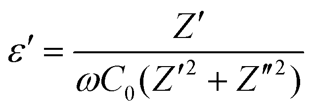
We further analyzed the AC impedance data to determine the dielectric properties of the prepared silicates. Dielectric permittivity is a crucial parameter for identifying the ion transport and phase transformation mechanism within a system by visualizing the electrolyte capacitive behaviour.59 The dielectric constant (ε′) and dielectric loss (ε′′) can be found based on the following relationships.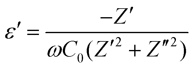 | (6) |
 | (7) |
Fig. 9a shows the real part of permittivity (ε′) as a function of frequency for all five silicates, including 5, 10, 15, 20-N3Sm and N5Sm. All ceramics exhibit a plateau with high ε′ values at low frequencies. N5Sm demonstrates an exceptionally high dielectric constant at low frequencies. This upturn at low frequencies corresponds to the electrode–electrolyte interface polarization. As the frequency continues to increase, the polarity of the field reversals becomes too rapid for the charge displacement to match the size of the conducting region.
 | ||
| Fig. 9 (a) Real permittivity as a function of frequency and (b) tangent loss as a function of frequency for all five silicates, including 5, 10, 15, 20-N3Sm, and N5Sm. | ||
Consequently, the oscillating carriers lack sufficient time to accumulate, preventing polarization. Beyond a specific frequency, the dielectric constant reaches saturation and approaches the steady-state value (ε∞). Therefore, as frequency increases, the dielectric constant decreases, consistent with the typical behaviour of ion-conducting materials.60,61 For compositions N5Sm and 15-N3Sm, electrode and dipole polarization increase due to the enhanced mobility of thermally activated charge carriers, resulting in higher dielectric constant values than the other three compositions. Additionally, the plateau observed at low frequencies shifts to higher frequencies for N5Sm and 15-N3Sm, indicating increased Na+ ion mobility and a higher dipole rotation frequency.62
The relaxation process during the conduction mechanism can be understood using the tangent loss plot as a function of frequency. It can be estimated using the ratio of the imaginary to the real part of permittivity based on the relation given in eqn (8):
 | (8) |
In Fig. 9b, the appearance of one peak for all five compositions is observed due to the dielectric loss caused by grain boundary polarization. N5Sm showed a shift in the peak to a higher frequency with a lower peak intensity of the loss curve than the other compositions. This typically indicates an increase in charge carriers (lower relaxation time) and a minor dielectric loss in the particular composition, implying better conduction.62 This decrease in relaxation time results from the fast sodium ion migration from one site to another neighbouring site, thus providing higher ionic conductivity for N5Sm, among other silicates developed in the work.
5 Conclusions
In summary, six compositions of sodium samarium silicates were prepared using the solid-state synthesis method. Among them, N5Sm demonstrated the highest ionic conductivity of 1.33 × 10⁻³ S cm−1 at 25 °C with an activation energy of 0.25 eV. N5Sm also exhibited a denser microstructure, with higher density and fewer impure phases, as confirmed by cross-sectional SEM analysis, Archimedes density measurements, and PXRD. Furthermore, the electronic conductivity of N5Sm was seven orders of magnitude lower than its ionic conductivity, effectively suppressing sodium dendrite growth and enhancing the sodium-ion transference number. Its stability window extends to 9 V, making N5Sm a promising electrolyte candidate for advanced high-voltage energy storage applications. Based on these findings, sodium samarium silicates, particularly N5Sm, stand out as excellent sodium ion conductors for future sodium metal batteries.Author contributions
Methodology, experimental work, data collection, investigation and analysis, validation, and writing – original draft, review and editing: Abinaya Sivakumaran; investigation, draft review and editing: Vishnu Surendran; draft review, discussion, and editing: Shantel Butler; discussion and funding: Samuel Reid; supervision, conceptualization, project administration and funding, communication, draft review and editing: Venkataraman Thangadurai.Data availability
All data supporting the findings of this study are included in this article and its ESI.†Conflicts of interest
There are no conflicts to declare.Acknowledgements
This work was funded by the Natural Sciences and Engineering Research Council of Canada (NSERC) Collaborative Research and Development (CRD) Grants and Geometric Energy Corporation. We extend our gratitude to Dr. Alfred Samson for his contributions during the early stages of the work. Abinaya Sivakumaran would like to thank Prof. Todd C Sutherland for his invaluable mentorship during her graduate program.References
- C. Zhou, S. Bag and V. Thangadurai, ACS Energy Lett., 2018, 3, 2181–2198 CrossRef CAS.
- J. Y. Hwang, S. T. Myung and Y. K. Sun, Chem. Soc. Rev., 2017, 46, 3529–3614 RSC.
- J. Deng, W.-B. Luo, S.-L. Chou, H.-K. Liu and S.-X. Dou, Adv. Energy Mater., 2018, 8, 1701428 CrossRef.
- H. Peng, J. Huang, X. Cheng and Q. Zhang, Adv. Energy Mater., 2017, 7, 1700260 Search PubMed.
- X. Y. Li, S. Feng, Y. W. Song, C. X. Zhao, Z. Li, Z. X. Chen, Q. Cheng, X. Chen, X. Q. Zhang, B. Q. Li, J. Q. Huang and Q. Zhang, J. Am. Chem. Soc., 2024, 146, 14754–14764 CrossRef CAS PubMed.
- S. Zhai, A. M. Abraham, B. Chen, Z. Fan, J. Hu, Z. Cai and V. Thangadurai, Carbon, 2022, 195, 253–262 CrossRef CAS.
- T. Boteju, A. M. Abraham, S. Ponnurangam and V. Thangadurai, J. Phys. Chem. C, 2023, 127, 4416–4424 CrossRef CAS.
- X. Xu, D. Zhou, X. Qin, K. Lin, F. Kang, B. Li, D. Shanmukaraj, T. Rojo, M. Armand and G. Wang, Nat. Commun., 2018, 9, 1–12 CrossRef PubMed.
- R. M. Dell and P. T. Moseley, J. Power Sources, 1981, 6, 143–160 CrossRef CAS.
- H. Engstrom, J. B. Bates, W. E. Brundage and J. C. Wang, Solid State Ionics, 1981, 2, 265–276 CrossRef CAS.
- J. B. Goodenough, H.-P. Hong and J. A. Kafalas, Mater. Res. Bull., 1976, 11, 203–220 CrossRef CAS.
- F. Li, M. Hou, L. Zhao, D. Zhang, B. Yang and F. Liang, Energy Storage Mater., 2024, 65, 1747–1770 Search PubMed.
- K. B. Hueso, M. Armand and T. Rojo, Energy Environ. Sci., 2013, 6, 734–749 RSC.
- S. K. Pal, R. Saha, G. V. Kumar and S. Omar, J. Phys. Chem. C, 2020, 124, 9161–9169 CrossRef CAS.
- Q. Ma, M. Guin, S. Naqash, C. L. Tsai, F. Tietz and O. Guillon, Chem. Mater., 2016, 28, 4821–4828 CrossRef CAS.
- J. Wu, R. Zhang, Q. Fu, J. Zhang, X. Zhou, P. Gao, C. Xu, J. Liu and X. Guo, Adv. Funct. Mater., 2021, 31, 2008165 CrossRef CAS.
- B. A. Maksimov, Y. A. Kharitonov and A. N. V. Belov, Sov. Phys. Dokl., 1974, 18, 763–765 Search PubMed.
- R. D. Shannon, B. E. Taylor, T. E. Gier, H. Y. Chen and T. Berzins, Inorg. Chem., 1978, 17, 958–964 CrossRef CAS.
- T. T. Okura, H. Monma and K. Yamashita, Phosphorus Res. Bull., 2004, 17, 91–94 CrossRef CAS PubMed.
- T. Okura, T. Takahashi, H. Monma and K. Yamashita, Solid State Ionics, 2008, 179, 1291–1295 CrossRef CAS.
- T. Okura, M. Tanaka, H. Kanzawa and G. Sudoh, Solid State Ionics, 1996, 86–88, 511–516 CrossRef CAS.
- T. Okura, H. Monma and K. Yamashita, J. Ceram. Soc. Jpn., 2004, 112, S685–S689 Search PubMed.
- T. Okura, H. Monma and K. Yamashita, Solid State Ionics, 2004, 172, 561–564 CrossRef CAS.
- T. Okura, H. Monma and K. Yamashita, J. Eur. Ceram. Soc., 2006, 26, 619–622 CrossRef CAS.
- J. Schilm, R. Anton, D. Wagner, J. Huettl, M. Kusnezoff, M. Herrmann, H. K. Kim and C. W. Lee, Materials, 2022, 15, 1104 CrossRef CAS PubMed.
- G. Sun, X. Yang, N. Chen, S. Yao, X. Wang, X. Jin, G. Chen, Y. Xie and F. Du, Energy Storage Mater., 2021, 41, 196–202 CrossRef.
- A. Yang, R. Ye, X. Li, Q. Lu, H. Song, D. Grüner, Q. Ma, F. Tietz, D. Fattakhova-Rohlfing and O. Guillon, Chem. Eng. J., 2022, 435, 134774 CrossRef CAS.
- A. Yang, R. Ye, H. Song, Q. Lu, X. Wang, E. Dashjav, K. Yao, D. Gruner, Q. Ma, F. Tietz and O. Guillon, Carbon Energy, 2023, 12, e371 CrossRef.
- A. Sivakumaran, A. J. Samson, A. A. Bristi, V. Surendran, S. Butler, S. Reid and V. Thangadurai, J. Mater. Chem. A, 2023, 11, 15792–15801 RSC.
- A. Michalak, S. Behara and A. Reddy, ACS Appl. Mater. Interfaces, 2024, 16, 7112–7118 CrossRef CAS PubMed.
- G. Sun, C. Lou, B. Yi, W. Jia, Z. Wei, S. Yao, Z. Lu, G. Chen, Z. Shen, M. Tang and F. Du, Nat. Commun., 2023, 14, 1–11 Search PubMed.
- A. Sivakumaran, A. J. Samson and V. Thangadurai, Energy Technol., 2023, 2201323 CrossRef CAS.
- B. Yi, Z. Wei, W. Jia, G. Sun, W. Si, S. Yao, G. Chen and F. Du, Nano Lett., 2024, 24, 8911–8919 CrossRef CAS PubMed.
- H. Li, X. Jiang, J. Zhang and J. Zhang, Mater. Today Commun., 2023, 34, 105203 CrossRef CAS.
- S. Narayanan, S. Reid, S. Butler and V. Thangadurai, Solid State Ionics, 2019, 331, 22–29 CrossRef CAS.
- G. Sun, X. Yang, N. Chen, S. Yao, X. Wang, X. Jin, G. Chen, Y. Xie and F. Du, Energy Storage Mater., 2021, 41, 196–202 CrossRef.
- H. Park, K. Jung, M. Nezafati, C. S. Kim and B. Kang, ACS Appl. Mater. Interfaces, 2016, 8, 27814–27824 CrossRef CAS PubMed.
- S. Shalini, P. Sandhyarani, Y. S. Rao, D. Chakravarty and R. Subasri, Ceram. Int., 2012, 38, 295–300 CrossRef CAS.
- T. Okura, H. Monma and K. Yamashita, Phosphorus Res. Bull., 2006, 20, 111–118 CrossRef CAS.
- A. Yang, K. Yao, M. Schaller, E. Dashjav, H. Li, S. Zhao, Q. Zhang, M. Etter, X. Shen, H. Song, Q. Lu, R. Ye, I. Moudrakovski, Q. Pang, S. Indris, X. Wang, Q. Ma, F. Tietz, J. Chen and O. Guillon, eScience, 2023, 3, 100175 CrossRef.
- K. Funke, Solid State Ionics, 1997, 94, 27–33 CrossRef CAS.
- J. C. Dyre, P. Maass, B. Roling and D. L. Sidebottom, Rep. Prog. Phys., 2009, 72, 046501 CrossRef.
- J. C. Dyre, J. Appl. Phys., 1988, 64, 2456–2468 CrossRef.
- B. V. Lotsch and J. Maier, J. Electroceram., 2017, 38, 128–141 CrossRef.
- L. C. De Jonghe, L. Feldman and A. Beuchele, J. Mater. Sci., 1981, 16, 780–786 CrossRef CAS.
- J. Schoonman and J. R. Macdonald, Solid State Ionics, 1981, 5, 617–620 Search PubMed.
- F. Han, A. S. Westover, J. Yue, X. Fan, F. Wang, M. Chi, D. N. Leonard, N. J. Dudney, H. Wang and C. Wang, Nat. Energy, 2019, 4, 187–196 CrossRef CAS.
- A. J. Samson, K. Hofstetter, E. Wachsman and V. Thangadurai, J. Electrochem. Soc., 2018, 165, A2303–A2311 CrossRef CAS.
- H. Rusdi, N. S. Mohamed, R. H. Y. Subban and R. Rusdi, J. Sci.:Adv. Mater. Devices, 2020, 5, 368–377 Search PubMed.
- J. A. S. Oh, L. He, B. Chua, K. Zeng and L. Lu, Energy Storage Mater., 2021, 34, 28–44 Search PubMed.
- S. Lou, F. Zhang, C. Fu, M. Chen, Y. Ma, G. Yin and J. Wang, Adv. Mater., 2021, 33, 2000721 CrossRef CAS PubMed.
- G. V. Alexander, O. V. Sreejith, M. S. Indu and R. Murugan, ACS Appl. Energy Mater., 2020, 3, 9010–9017 CrossRef CAS.
- D. Li, X. Wang, Q. Guo, X. Yu, S. Cen, H. Ma, J. Chen, D. Wang, Z. Mao and C. Dong, Carbon Energy, 2023, 5, 1–9 Search PubMed.
- S. Bag, H. Murarka, C. Zhou, A. Bhattacharya, D. Jokhakar, V. G. Pol and V. Thangadurai, ACS Appl. Energy Mater., 2020, 3, 8475–8486 CrossRef CAS.
- H.-B. Sun, J.-Z. Guo, Y. Zhang, T. Wei, Y.-X. Zhou, L.-L. Zhang, X.-L. Wu, Y. Huang and W. Luo, ACS Appl. Mater. Interfaces, 2019, 11, 24192–24197 CrossRef CAS PubMed.
- N. Horiuchi, K. Ryu, A. Nagai, T. Okura and K. Yamashita, Open Ceram., 2021, 8, 100175 CrossRef CAS.
- J. Hüttl, W. Cai, D. Wagner, J. Schilm, M. Kusnezoff, K. Nikolowski, N. Shaji, C. W. Lee, M. Partsch and A. Michaelis, Solid State Ionics, 2022, 376, 115856 CrossRef.
- L. Liu, Y. Xu, X. Zhou, W. Guo, J. Li, X. Guo and Y. Jiang, J. Solid State Chem., 2024, 336, 124781 Search PubMed.
- M. K. Chong, Z. Zainuddin, F. S. Omar, M. H. H. Jumali and M. N. M. Ansari, J. Energy Storage, 2024, 90, 111873 CrossRef.
- A. K. Baral, S. Narayanan, F. Ramezanipour and V. Thangadurai, Phys. Chem. Chem. Phys., 2014, 16, 11356–11365 RSC.
- A. K. Baral and V. Sankaranarayanan, Physica B: Condens. Matter, 2009, 404, 1674–1678 Search PubMed.
- B. P. Dubey, A. Sahoo, V. Thangadurai and Y. Sharma, Solid State Ionics, 2020, 351, 115339 CrossRef CAS.
Footnote |
| † Electronic supplementary information (ESI) available. See DOI: https://doi.org/10.1039/d4eb00021h |
| This journal is © The Royal Society of Chemistry 2025 |