
 Open Access Article
 This Open Access Article is licensed under a
 Creative Commons Attribution 3.0 Unported Licence
Extrinsic and intrinsic factors for electrochemical reduction of carbon dioxide on heterogeneous metal electrocatalysts
Mulatu Kassie
Birhanu
 a,
Begüm
Ünveroğlu Abdioglu
*a and
Ahmet
Uçar
*bc
a,
Begüm
Ünveroğlu Abdioglu
*a and
Ahmet
Uçar
*bc
aAnkara Yıldırım Beyazıt University, Faculty of Engineering and Natural Sciences, Department of Metallurgy and Materials Engineering, 06010, Ankara, Turkey. E-mail: bunveroglu@aybu.edu.tr
bAnkara Yıldırım Beyazıt University, Faculty of Engineering and Natural Sciences, Department of Energy Systems Engineering, 06010, Ankara, Turkey. E-mail: ahmet.ucar@aybu.edu.tr
cKing Abdullah University of Science and Technology (KAUST), Biological and Environmental Science and Engineering (BESE) Division, Thuwal, 23955-6900, Saudi Arabia
First published on 2nd December 2024
Abstract
Excessive CO2 emissions from the traditional consumption of fossil fuels have led to severe environmental and ecological issues, including global temperature rise, atmospheric carbon imbalance, and expansion of desertification. To address these challenges, various green technologies and remediation techniques aimed at reducing CO2 emissions are being implemented worldwide. Among them, the electrochemical reduction (ECR) of CO2 into value-added fuels and chemicals has emerged as a promising strategy to complete the anthropogenic carbon cycle and promote sustainable development. However, the ECR of CO2 faces several challenges, including the inherent properties of CO2, harsh reduction conditions, poor catalytic performance, limited catalyst efficiency and stability, intermediate properties, competitive side reactions, and low product selectivity. Addressing these challenges requires a comprehensive understanding of both the extrinsic and intrinsic factors that influence the reduction process. This review provides a detailed examination of these factors, along with insights into the reduction principles and reaction mechanisms for the ECR of CO2. Extrinsic factors include the reduction temperature, electrolyte type and concentration, reaction cell design, catalyst/mass loading, electrolyte pH, pressure, and applied potential. Intrinsic factors encompass the active site properties of electrocatalysts, binding strength between CO2 and the reduction intermediates on the catalyst surface, electroactive surface area, nanocatalyst dimension, surface structure, morphology, and composition of the electrocatalyst. Additionally, we discuss advanced influences, such as electric fields, surface strain, dangling bonds, structural defects, ionomers, and hydrophobicity of electrocatalysts. The role and impact of each factor are analyzed, with a particular focus on the stability, reduction efficiency, and selectivity of the electrocatalyst and the product distribution in the ECR of CO2. This review aims to provide valuable insights for advancing the design and optimization of efficient and selective electrocatalysts to effectively address global CO2 emissions.
 Mulatu Kassie Birhanu | Mulatu Kassie Birhanu is a Postdoctoral Researcher at Ankara Yildirim Beyazit University, Department of Metallurgy and Materials Engineering under TÜBİTAK-TWAS-UNESCO Postdoctoral Fellowship Program. He obtained his PhD degree in Chemical Engineering at the National Taiwan University of Science and Technology (NTUST) in 2019. His research interests are catalysis, electrocatalytic reduction of CO2, analytical chemistry, material chemistry, synthesis and application of nanomaterials. |
 Begüm Ünveroğlu Abdioglu | Begüm Ünveroğlu Abdioglu is an Assistant Professor at Ankara Yildirim Beyazit University, Department of Metallurgy and Materials Engineering. She received her PhD from the University of Virginia, in Materials Science. Her research interests are semiconductor and composite materials, testing and control of materials, chemical and electrochemical properties, electroplating and material characterization. |
 Ahmet Uçar | Ahmet Uçar is an Assistant Professor at Ankara Yildirim Beyazit University, Department of Energy Systems Engineering. Also, he is currently working as a Visiting Researcher at King Abdullah University of Science and Technology (KAUST), Organic Bioelectronics Laboratory. He obtained his PhD from the University of Edinburgh in the field of electrochemical sensors. His research interests include electrochemical systems for health and energy applications, bioanalytical techniques, nanomaterials and surface chemistry. |
1. Introduction
1.1 Background
Recently, worldwide energy-related CO2 emissions reached 31.5 billion tons due to the increase in human activities, rapid population growth, economic expansion, and consumption of excess fossil fuels.1 As a significant threat to humanity, global climate change has an impact on both natural and economical aspects of the world. CO2, methane, water vapor, ozone, freons (chlorofluorocarbon compounds), and nitrogen oxides are the main greenhouse gases contributing to climate change. Among them, CO2, which obviously and gradually contributes to the greenhouse effect, is the primary cause of global warming. If CO2 emissions keep increasing at the current rate, global warming is expected to exceed 1.5 °C by 2030. The Paris Agreement, signed by world leaders from 195 countries in 2016, marked an important milestone in terms of developing strategies to overcome climate change issues. They agreed to limit the increase in global warming to less than 2 °C compared to pre-industrial levels by the end of the 21st century.2Environmental and energy issues represent one of the biggest challenges faced by mankind in this century.3–6 Energy consumption is rapidly increasing, and it is expected to reach a level approximately two times greater by 2050 compared to the current consumption level.7 Despite the tremendous efforts to develop renewable energy sources, the majority of energy used is derived from non-renewable fossil fuels. The use of natural resources throughout history, especially fossil fuels, has contributed significantly to unprecedented human development.3,5,8–12 However, the inappropriate and excessive utilization of fossil fuels without consideration and development of better mitigation techniques has led to the adverse effects of CO2 emission on the atmosphere. Consequently, CO2 emissions and their levels in the atmosphere are increasing continuously, mainly because of the increase in the number of power plants, industries, vehicles, and other activities that consume fossil fuels as an energy source. Currently, the level of CO2 has reached an approximate concentration of 423 ppm (≈0.04% by volume). This level/concentration has a significant impact on disrupting the atmosphere and has become one of the leading causes of global warming, which is eventually expected to lead to higher temperatures on the Earth, expanded desertification, deforestation, severe storms, increased drought, warming/rising oceans, loss of land and ocean species, food scarcity, health risks, poverty, and displacement. In general, this seriously threatens the community of living organisms and the ecological balance.3,4,13–19
Nowadays, significant efforts have been devoted to developing and promoting green (sustainable) energy sources to minimize carbon emissions. However, most of the energy consumption is still related to non-renewable energy sources, specifically fossil fuels, resulting in an increase in the CO2 level in the atmosphere and devastating the carbon balance. Therefore, intensive efforts have been dedicated to developing different techniques to mitigate the high level of CO2, including its storage, conversion, and capture. Furthermore, carbon capture, conversion and storage (CCUS) technology based on catalytic, photocatalytic, and electrocatalytic conversion is a new and promising approach for effectively reducing the CO2 emissions and concentration in ambient air. CCUS is the most important step to direct how the scientific community can transform CO2 into usable and essential fuels/chemicals through electrocatalytic reduction. The technologies of CO2 capture can be divided into three types, i.e. a) pre-combustion, b) post-combustion, and c) oxy-fuel combustion methods. Little research has been conducted on the application of pre-combustion and oxy-fuel combustion technologies. These methods require appropriate materials and certain conditions to meet high-temperature requirements. Post-combustion capture is a widely applicable, mature technology with good CO2 efficiency, selectivity and effectiveness.2–4,20–22 In the ECR of CO2, the preparation of selective catalysts towards the formation of high energy density chemicals such as C2+ products (alcohols and hydrocarbons) is vital. Next, the commercialization of the electrocatalytic reduction of CO2 at the industry level is crucial for the use of the reduced products/chemicals as fuels. In this context, collaboration between industries that emit CO2 and technologists focused on converting CO2 into fuels is vital. All the aforementioned activities are essential tasks in guiding and assisting the community in utilizing the electrocatalytic reduction of CO2 as an alternative energy source.
Among the alternative processes, the electrocatalytic conversion of CO2 is the most widely applicable, as it can effectively convert this toxic gas into essential chemicals with high energy density, such as carbon monoxide, alcohols, hydrocarbons and formate. Therefore, managing and minimizing gas emissions through various methods such as electrochemical, photochemical, biochemical, hydrothermal and thermochemical reduction of CO2, are vital for converting into valuable chemicals that serve as alternative energy sources. This approach will not only reduce or eliminate the effects of global warming but also minimize the consumption of natural resources.13,23–29
The reutilization of emitted CO2 as a novel feedstock for the production of new compounds strongly aligns with sustainable infrastructure and green chemistry principles. Among the many alternatives, the electrochemical reduction of CO2 is simple, emerging, promising and novel technology. The advantages of the ECR of CO2 are as follows:2,4,8,23,30–35
- The reduction process is carried out at ambient temperature and pressure.
- The process can be easily controlled and tuned by adjusting external parameters such as the applied voltage, pH, type and concentration of electrolyte.
- The electricity consumed is derived from renewable resources, meaning that no additional CO2 is generated during the reduction process.
- The final products obtained are fuels and essential chemicals, with water and greenhouse gas CO2 being consumed. Additionally, the electrolyte can be fully recycled.
Generally, the conversion efficiency of CO2 ECR is significantly higher than that of other conversion techniques. Effective, efficient and selective electrocatalysts can reduce CO2 into the desired products with nearly 100% Faradaic efficiency (%FE). To enhance the %FE of each reduction product, the selection and methods for the preparation of the electrocatalyst, including the supporting material, play a great role.3,4,36–42 ECR of CO2 is a promising technique for sustainable energy conversion and storage.4 If this reduction process can be realized at a reasonable cost and efficiency, fuels and essential chemicals can be generated sustainably, enabling a zero-emission energy conversion cycle.43–46 Specifically, the production of C2 products, which commonly have higher energy densities and values than simpler products such as H2 and CH4, is attractive for applications in the chemical industry, energy storage and transportation.44,47–49
1.2 Motivation
The main objective here is to identify the parameters (both extrinsic and intrinsic) for analyzing the impacts and roles of each factor in the ECR of CO2, and to investigate the gaps in research related to these phenomena. As indicated in the previous section, achieving effective and efficient electrocatalytic reduction of CO2 depends on factors such as the properties, nature, environmental conditions and stability of the electrocatalyst. These factors can generally be classified as extrinsic (external) and intrinsic (internal). Extrinsic factors are related to parameters influenced by external conditions such as temperature, pressure, reaction cell, electrolyte solution, ionomers, hydrophobicity, and applied potential. Intrinsic factors pertain to the performance, nature, and properties of the electrocatalyst, including electrochemical surface area, particle size, binding interactions, active sites, electric field, strain effects, and composition. We believe that analyzing and understanding these factors is highly significant for securing the effective and efficient conversion of CO2 into usable, energy-rich and green chemicals. However, only a limited number of studies have been published thus far, with limited elaboration on the factors affecting the electrocatalytic reduction of CO2.3,4,15,50 Additionally, the previous works lack a well-structured categorization and detailed discussion of these factors.8,13,30,51,52 The potential individual impacts of each factor on CO2 reduction should be investigated for a comprehensive analysis. Therefore, the motivation of this review is to identify and categorize each factor (see Section 2) with an adequate discussion based on previous research in this field, along with our perspectives and outlooks. We also present new insights into the reduction principles and reaction mechanisms concisely.1.3 Concepts on electrocatalytic reduction of CO2
Typically, the electroreduction of CO2 is conducted in a divided cell (H-cell) containing both anode and cathode electrodes. An ion exchange membrane is required between these electrodes to prevent the flow of electrons by allowing the passage of protons within the compartments. This scenario is important to avoid the further oxidation of the intermediates and products at the cathode during the electrochemical reduction process. At the cathode, the hydrogen evolution reaction (HER) is expected to take place in a common electrolyte solution in addition to the reduction of CO2. It is known that HER is considered a competitive or side reaction of CO2 ECR. This side reaction is one of the challenges in the selectivity of this electrochemical reduction process.Three crucial steps are carried out during the electrochemical reduction of CO2, as shown in Fig. 1A and B.
 | ||
| Fig. 1 (A) Principles of ECR of CO2 on the surface of heterogeneous electrocatalysts. (B) Detailed scheme showing the role of the anode and cathode in the reduction process. | ||
i. Adsorption of CO2 on the electrode surface.
ii. Charge transfer reaction with harmonization of H+/e− to form intermediates.
iii. Desorption or removal of products on the active sites of electrocatalyst during the electroreduction of CO2.
1.4 Reduction mechanism of ECR of CO2
The electrocatalytic reduction of CO2 involves several steps, including adsorption, reduction, and dissociation of CO2 and the reduction intermediates.53–61 Primarily, CO2 molecules are adsorbed on the surface of the catalyst through chemical or physical adsorption. During the adsorption process, chemical bonds are formed between CO2 and the catalyst atoms, and then charge redistribution occurs between the species.51,54,62–67 Following the chemisorption of CO2 on the catalyst surface, it typically accepts electrons from the catalyst and a reduction reaction occurs. This process can be invigorated by an applied potential, which enables the reduction to proceed. The formation of various products requires different potentials to drive the reactions, with the specific potential required for each product provided in Table 1.51| Reaction | E 0/V (vs. RHE) |
|---|---|
| CO2 + e− → CO2− | −1.900 |
| CO2 + 2H+ + 2e− → CO + H2O | −0.530 |
| CO2 + 2H+ + 2e− → HCOOH | −0.610 |
| CO2 + 4H+ + 4e− → HCHO + H2O | −0.480 |
| CO2 + 6H+ + 6e− → CH3OH + H2O | −0.380 |
| CO2 + 8H+ + 8e− → CH4 + 2H2O | −0.240 |
| 2CO2 + 10H+ + 10e− → CH3CHO + 3H2O | −0.06 |
| 2CO2 + 12H+ + 12e− → C2H4 + 4H2O | −0.340 |
| 2CO2 + 14H+ + 14e− → C2H3 + 4H2O | −0.270 |
| 3CO2 + 16H+ + 16e− → C2H5CHO + 5H2O | −0.09 |
| 2CO2 + 2H+ + 2e− → H2C2O4 | −0.913 |
| 2CO2 + 2e− → C2O42− | −1.003 |
| 2CO2 + 12H+ + 12e− → C2H5OH + 3H2O | −0.330 |
| 3CO2 + 18H+ + 18e− → C3H7OH + 5H2O | −0.320 |
Initially, the transfer of H+/e− to CO2 occurs in the electrochemical CO2 reduction process (Fig. 2).69 Both carbon and oxygen can be used by the resultant intermediate to bind to the electrode surface. Electrons from the catalyst and protons from the electrolyte solution are transferred to CO2 molecules, which progressively lose oxygen atoms to create compounds in a more reduced state, including CO, CH3OH and other products. Subsequently, the product molecules are desorbed or released from the active sites on the catalyst surface, followed by the eventual dissociation of the product molecules. Over the past few decades, researchers have used common metal electrocatalysts such as Cu, Au, Ag, and Sn to study the reduction mechanism of electrocatalysts.70,71 The formation of the CO2˙− intermediate is typically regarded as the rate-determining step in the ECR of CO2. Stabilizing essential intermediates for the effective and efficient production of reduction products is one of the primary functions of electrocatalysts. Based on the capacity of metal electrocatalysts to bind various intermediates and end products on their surface, metals can be categorized into three classes.34,72,73 In the ECR of CO2, Sn, Hg, Pb, and In fall into class 1 and can generate formate or formic acid.8,74 In the initial stages of the reduction process, formate or formic acid is produced as a result of the limited interaction or binding of these metals with the CO2˙− intermediate.72 Alternatively, Ag, Au, Pd, and Zn are categorized as class 2 metals because of their significant ability to bind *COOH, which enables its further reduction. The *CO intermediate is weakly bonded on these metal surfaces. CO is easily desorbable from the surface as a significant reduction product due to this phenomenon. Cu is the unique metal in class 3 and has the greatest capacity to bind the intermediates (*CO, *COH, and *CHO) and transform CO2 into energy-rich compounds such as alcohols (methanol, ethanol and propanol) and hydrocarbons (methane, ethylene, etc.).75–79
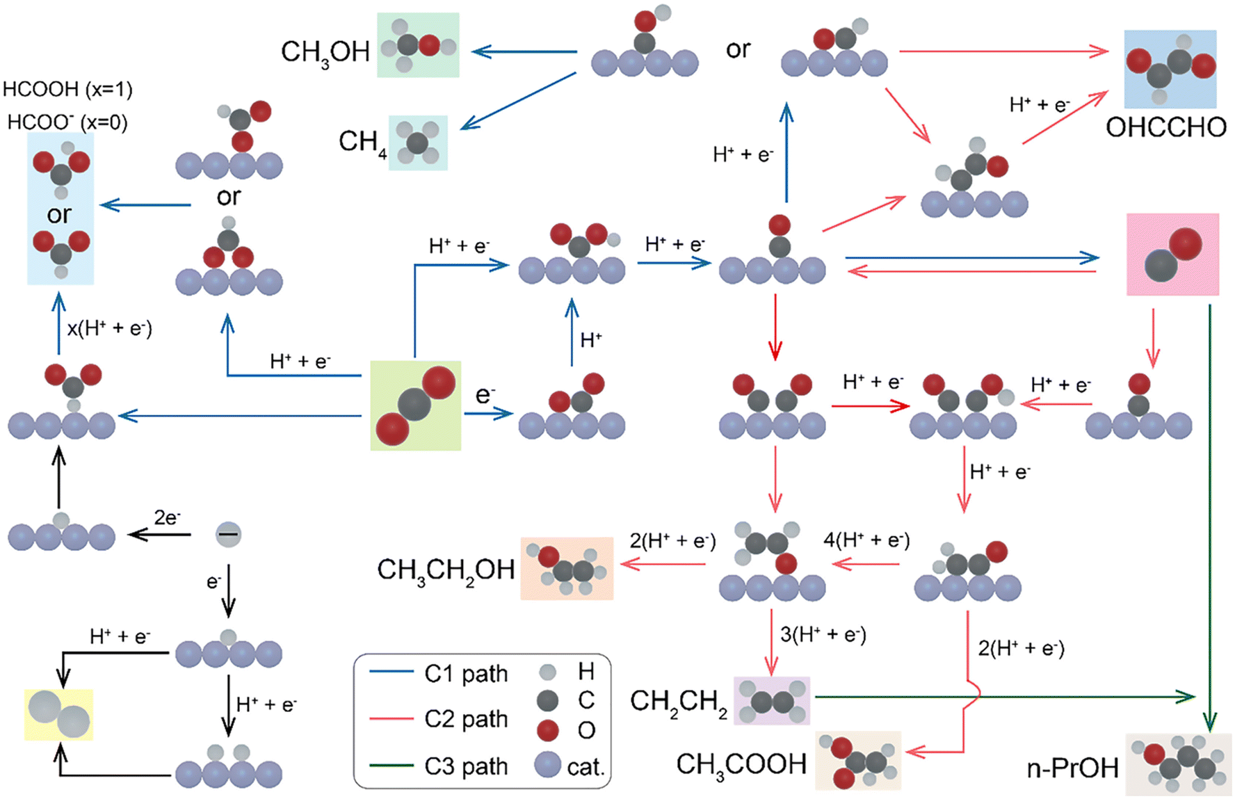 | ||
| Fig. 2 Possible carbon dioxide reduction reaction pathways for C1 and C2 products.69 ©Elsevier. | ||
Copper plays a unique role in the ECR of CO2 given that it is the only metal that can generate higher hydrocarbons and oxygenates and it can form a wide range of compounds. The ability of copper catalysts to produce a wide range of products demonstrates the complexity of the reduction reaction. The vital reaction step that distinguishes the paths for single and multicarbon products is the formation of C–C bonds. Bidentate *CO*CO is an intermediate species that is produced when two *CO species dimerize, which is frequently regarded as a crucial step in the creation of C–C bonds. Due to its low cost, H2O is the most feasible solvent for CO2 reduction. In the case of reactions with a pH greater than 7, the proton supply is regulated by the flow of H2O to the interface. The reactivity and selectivity are significantly impacted by the availability of the proton donor, which is H2O, at the interface given that the reduction of CO2 to any product (except that of C2O42−) requires a proton transfer step. For instance, its pH-dependent reaction rate (on a pH-independent reference scale) indicates that the synthesis of CH4 includes proton transfer in its rate-limiting step (RLS). It is believed that the coupling of two CO*, which has a pH-independent reaction rate, is the RLS for C2 products, such C2H4 formation. It should be mentioned that a growing amount of research indicates that the rate at which C2 products are generated is not determined by C–C dimerization. Instead, these investigations assume that CO* protonation to COH* is essential. However, the precise underlying process in the synthesis of C2 products remains a topic of active debate, despite these revelations.80,81 H2O is present in all aqueous reaction settings, despite the fact that pH-dependent experiments have provided valuable insights. As a result, the reaction is always mediated by a valid proton donor. Therefore, it is essential to fully understand the basic mechanisms through which H2O, the primary proton donor in CO2 reduction, influences the branching between the C1 and C2+ pathways.82
Generally, formate, CO and lately reduced CO2 (hydrocarbons and alcohols) are the major products of class 1, class 2 and class 3, respectively. It is important to consider the presence of HER as a competitive reaction across all metal groups, particularly on metal electrocatalysts containing Pt, Ti, Fe and Ni, as these are known to be selective for HER. With this in mind, by tuning the binding strength between reduction intermediates and metal surfaces, it is possible to control the types of reduction products in this process. Liu et al. studied this using density functional theory (DFT) and provided insights into the mechanism of electrochemical CO2 reduction over single-atom copper alloy catalysts. According to this study, as shown in Fig. 3A and B, the most stable adsorption sites are classified into two groups, where on Ag, Al, Au, Ge, Ga, Pb, Si, and Sn@Cu, the adsorption site is H2, denoted as the AD mode. In contrast, on Fe, Ru, Pd, Co, Ni, and Pt@Cu, the strongest adsorption site is T1, which is adsorbed directly on the top site of the metal. Comparing the adsorption energy of *CO on the top site of M(T1) and hollow site (H1 and H2) allows the identification of the preferred site. They performed an investigation into the formation of intermediates (*COOH, *CO, *CHO, *COH, **OCH3, *O + CH4, *OH and * + H2O) to reveal the free energy profiles for the C1 products on M@Cu SAAs. CO and HCOOH are commonly known as two-electron reduction products in ECR of CO2.4,8,54,83,84
 | ||
| Fig. 3 Adsorption energies of *CO on M@Cu and corresponding configurations. Adsorption energies on (A) M@Cu(111) and (B) (100) surfaces. (C–R) *CO adsorption configurations on M@Cu(111).54 | ||
Different types of catalysts and reaction conditions are expected to show different reaction pathways and product selectivity, leading to different possibilities for the formation mechanisms of various C1 and C2+.85,86 Hu et al. proposed the reaction mechanisms, describing that CO2 initially forms the COOH intermediate, which is then converted to *CO (considered the key intermediate). *CO forms various types of intermediates through different dimerization and hydrogenation mechanisms depending on the reaction conditions. Generally, many studies reveal that the reduction reaction process is characterized by a variety of reaction pathways and product selectivity, in which the specific types of multi-carbon products depend on the reaction conditions and catalyst type and nature.51,54,85,87,88
1.5 Selectivity of products on different types of metal electrocatalysts
Numerous studies conducted by Nitopi and others have shown that the metal employed as the cathode has a significant impact on the product selectivity. Sn has strong formic acid (HCOOH) selectivity. However, only Cu shows strong selectivity for the production of oxygenated molecules and multicarbon hydrocarbons, while Ag and Au show high selectivity for CO. Many other studies have also demonstrated that the product distributions seen on different catalysts are significantly influenced by the catalyst structure.19,89–91Even at low water concentrations, the competing hydrogen evolution process commonly reduces the selectivity of ECR of CO2, which can provide a sustainable method for producing chemicals and fuels. To alter the HER activity and selectivity of ECR of CO2, Gomes et al.92 adjusted the water solvation and dynamics in a range of aprotic solvents with various functional groups and physicochemical characteristics. They demonstrated that enclosing water in a robust hydrogen bond network can increase the HER onset potential by nearly 1 V. This team used a gold catalyst to obtain approximately 100% CO FE at water concentrations as high as 3 M. Moreover, they maintained over 100% FE towards CO with minimal carbonate loss during prolonged electrolysis with an earth-abundant zinc catalyst in a slightly acidic environment. Regarding significant electrochemical reactions, their study revealed descriptors that guide electrolyte design and offers insights into controlling the reactivity of water.
An attractive and sustainable method for effective CO2 conversion and utilization is to produce extensively reduced (net number of electrons transferred per carbon atom of more than 2e−) products from ECR of CO2. Cu-based bimetallic electrocatalysts are the focus of current research on profoundly reduced products in the ECR of CO2, and notable progress has been made in recent years to increase their activity and selectivity. Nevertheless, the bottleneck in Cu-based ECR of CO2 technology continues to be its inherent low selectivity (wide product profile) and poor stability. In this case, electrocatalysts that are not based on copper show promise as options for selectively converting CO2 into deeply reduced compounds or a variety of products.93
ECR of CO2 to ethanol and ethylene enables the long-term storage of renewable electricity in valuable multi-carbon (C2+) chemicals. Metal electrocatalysts are grouped into different categories based on the types of reduction products they facilitate. Specifically, electrocatalysts are classified as CO-selective, formate-selective, or favorable for the formation of hydrocarbons, including multi-carbon hydrocarbons such as C2H4.5,94 Cu is particularly notable for its unique property of having a strong interaction and binding energy with CO2 reduction intermediates.56,95,96 This property promotes the formation of hydrocarbons but also leads to significant side reactions associated with HER. Cu not only produces hydrocarbons in a distinctive manner, but is also a catalyst for the formation of various reduction products. Bimetallic electrocatalysts can generate more efficient and selective reduction products compared to the corresponding monometallic counterparts.3,7,8,36,97–106 However, it is important to understand that when we refer to an electrocatalyst as being selective towards a specific product, this does not mean that the reduction produces 100% of that product. Instead, it means that the majority of the reduction product will be the desired product, along with small amounts of other products. Electrocatalysts that are selective for formate typically generate lower current densities, while precious metals that are selective for CO generally generate higher current densities. Li et al. identified volcano trends in their product analysis (Fig. 4A–C) between activity toward CO, HCOO− and H2 formation and the nature of the transition metal in MNx sites, with Fe and/or Co at the top of the volcano, depending on the electrochemical potential over atomically dispersed metal sites on nitrogen-doped carbon.55,107,108
 | ||
| Fig. 4 (A) Product analysis, % FE. (B) Partial current densities at (a) −0.6 V and (b) −0.5 V vs. RHE obtained over MNC catalysts (M = Mn, Fe, Co, Ni, and Cu). (C) Volcano trends for the formation of formate. | ||
Bagger et al. proposed four non-coupled binding energies of intermediates as descriptors for predicting the product distribution in ECR of CO2. They compared the groups based on multiple binding energies of the intermediates calculated by density functional theory. It was found that three descriptors can explain the grouping, i.e., the adsorption energies of H*, COOH*, and CO*, and beyond CO*. In the case of beyond CO* intermediates, the production of alcohols and hydrocarbons is expected via the C–C coupling dimerization reaction. They also identified oxygen binding (adsorption energy of CH3O*) as an additional descriptor to describe alcohol formation in the reduction activities. Overall, the adsorption energy of H*, COOH*, CO*, and CH3O* can be used to differentiate, group, and describe the products in ECR of CO2 processes involving CO2, CO, and carbon–oxygen compounds. The product distribution and selectivity depends on the adsorption energy between these intermediates and electrocatalyst surfaces. This research group also identified experimental data for different metals in four groups based on the major product, assigning colors and showing the FE% including comparing the groups with multiple binding energies of intermediates (Fig. 5A). Fig. 5B shows the plot of FE% of ECR of CO2 as a function of the ΔEH* binding energy, indicating that the hydrogen binding energy is potentially the theoretical limiting factor for improving the FE% of the CO2 reduction reaction.109
 | ||
| Fig. 5 (A) Major product classification of metal catalysts for ECR of CO2 obtained from other experimental data. (B) FE% of ECR of CO2 as a function of ΔEH* (binding energy of H*). Reproduced with permission.109 ©John Wiley and Sons. | ||
Karapinar et al. studied the Cu–N–C material synthesized through a simple pyrolytic method, exclusively featuring single copper atoms with a CuN4 coordination environment, which is atomically dispersed in a nitrogen-doped conductive carbon matrix. This catalyst material achieved a FE% of 55% for the formation of ethanol in the electrochemical reduction (ECR) of CO2 in aqueous media under optimized conditions. When considering both C2-products (ethanol and ethylene), a total FE of 80% was recorded.110 This indicates that the novel CuN4 material serves as a selective electrocatalyst, with active sites that promote the formation of C2 products (ethanol and ethylene).
1.6 Highlights on aspects for the commercialization of ECR of CO2
ECR of CO2 presents a promising route for converting intermittent renewable energy into storable, valuable chemicals and fuel feedstocks.98 To scale this technology for industrial implementation, an intensive understanding of CO2 reduction reaction is essential for determining the optimal operating parameters. Currently, there is a growing demand for energy-rich chemicals such as hydrocarbons (methane, ethane, ethylene propane and butane), alcohols (methanol and ethanol) and ethylene glycol is increasing. In addition to conventional production methods, the commercial production of these chemicals through the ECR of CO2 is becoming increasingly important. The successful commercialization of ECR technology hinges on a comprehensive techno-economic analysis. Life-cycle assessments, technology evaluations, and operational cost analyses are crucial tools for addressing challenges in the ECR process. Key factors include the economic feasibility of various CO2 reduction products, sensitivity to CO2 reduction metrics, and evaluations of both economic and environmental sustainability, including whether the process is carbon-negative and profitable. Studies suggest that the cost of electricity and even CO2 itself are highly sensitive factors that influence overall production costs, highlighting the importance of efficient CO2 capture methods for successful commercialization. Furthermore, operational costs related to CO2 reduction, product separation, and electrolyzer efficiency are critical for techno-economic assessments. Recent studies have shown that the production of formate and carbon monoxide is more economical, as their production rates are comparable to commercially available methods and can be scaled up to industrial levels.111–115The feasibility of the process of ECR of CO2 for commercialization and the competitiveness of its products depends on several key indicators and parameters. Generally, techno-economic analysis reports have overlooked the interdependence among the FE, current density, and cell voltage in their commercialization analysis. The goal of studying techno-economic analysis is identifying maximally profitable products and the performance targets that should be achieved to ensure economic viability metrics, which include current density, FE, energy efficiency, and stability.112,113,116,117
Generally, the efficiency of the electrocatalyst, electrolyte selection in terms of type and concentration, quality of electrocatalyst characterization, types of cell reactor/design that are applicable for the reduction (H-cell type, flow cell, or other types), advancement of product quantification and separation are the key issues in the commercialization of ECR of CO2. A few studies have been conducted regarding the commercialization. In a recent study by Kumar et al., they reported a CO2 cost of $40 per t, electrolyzer cost of $5000 per m2 and electricity price of 2 cents per kW h−1.111,118,119 Verma et al. have introduced a gross-margin model to investigate the techno-economic feasibility of reaction products (specially C1 and C2 products), employing the maximum operating applied voltage (Vmax), minimum operating current density (jmin), FE, and catalyst durability as key parameters.113,116 Bushuyev et al. performed a techno-economic analysis with an electrolyzer cost of $500 per kW together with other predefined standard parameters. (e.g. F.E. = 90%; EE = 60%; electricity cost = $0.02 per kW h−1, and CO2 cost = $30 per ton). This study suggests that higher carbon products such as (CH2OH)2 and C3H7OH can be more attractive for commercialization due to their high demand and increasing prices in the market.26
Commercial or large-scale CO2 electrolysis can be achieved using gas diffusion electrodes (GDEs), which is an important step towards the wider implementation of carbon capture and utilization techniques. However, due to the complexity of the reaction, and also the substrate and the electrolyzer stack, there is still limited understanding on how the GDE performance is influenced by the complex interplay among the system parameters. GDEs are comprised of a porous conducting material with the electrocatalyst being deposited on its surface, which are immersed into the catholyte. The reactant i.e. CO2 is fed from the backside, either in a flow-through or flow-by configuration. The reaction occurs at 3-phase boundaries created by the catalyst, electrolyte and CO2 gas. This configuration reduces the depletion of CO2 at the reaction interface, enabling the reaction to operate at higher current densities. Furthermore, the porous structure of the GDE needs to be hydrophobic to allow gas transport while preventing the electrolyte flow. Various parameters, including pressure, catalyst loading, reactor geometry, electrolyte flow rate, electric resistance, wettability of the substrate, and conductivity, have been shown to influence the activity of GDEs. However, deconvoluting their interrelated effects can be challenging.120 Recently, researchers have devoted tremendous effort to commercialize the ECR of CO2 through the formation of formate and CO. The ECR of CO2 to formate is an emerging carbon utilization method that can be carried out at ambient temperature and pressure, which only requires two electrons, and has a high atom efficiency. In this case, efforts have shifted toward understanding how the design of the electrolyzer affects the efficiency and rate of the reaction. Regarding the commercialization process, optimization of the reaction conditions is an important step. Achieving high current densities is one of the critical issues restricting the commercialization of this technology. To achieve industrially applicable conditions, the generation of a high current density (>100 mA cm−2) using GDEs and flow reactors is required. In the past decade year, although GDE-based electrolyzers have frequently been reported to attain a few 100 mA cm−2, faster reaction rates are still necessary to enhance the process flexibility and reduce the capital costs required for peak-shaving of fluctuating, renewable energies. Löwe et al. synthesized a tin oxide nanoparticle-based, homogeneous single-layer gas diffusion electrode operating at current densities of up to 1.8 A cm−2. At this current density, over 70% FE was reported for the formation of formate. Parameters such as type of cation available in the electrolyte, hydrophobicity of the electrode and loading of the catalyst in the electrode were optimized and investigated specifically for this electrode to achieve the maximum current density (1.8 A cm−2), which is considered sufficient for the commercialization step.121,122
Ávila-Bolívar et al. studied the selective reduction of CO2 to formate, where they prepared carbon-supported 10 nm Bi nanoparticles using a simple, fast and scalable approach performed at room temperature. They reported a 100% FE at a low potential (−1.5 V vs. AgCl/Ag) with a formate concentration of about 55 mM. This group studied the output of FE% as a function of applied potential, which indicated that the efficiency for the formation of formate depends on the potential. Interestingly, they investigated the concentration of formate during a specific reduction time (3 h) at different potentials. They obtained the maximum formate concentration of 77 mM at −1.6 V. This concentration value decreased to 70 and 64 mM at −1.7 and −1.8 V, respectively. The evaluation of the FE of formate and its change in concentration during the 24 h experiment was reported. The results confirmed that after 4–5 h, the electrode begins to be less efficient and both the FE% and formate concentration decreased gradually. The FE% for formate, CO, hydrocarbons and alcohols and the electrocatalyst used, electrolyte solutions, applied potential and reactor type are described in Table 4 (sub-section 2.1.5).
Silver is one of the best metal electrocatalysts for the selective ECR of CO2 towards CO. The values of FE% for this reaction significantly depend on the quality of the surface modification of Ag. Buckley et al. revealed an approach to achieve 100% FE in ECR of CO2 towards the formation of CO using surface additive/modified Ag at a low potential. They reported the discovery of a quaternary ammonium surface additive on the surface of Ag, which alters the FE% for CO from 25% on Ag foil to 97% on modified Ag. According to the results, the Ag surface modified with 2-C16 showed the highest FE of 97% at −0.8 V vs. RHE, while the Ag surface modified using 1-C16 demonstrated a lower FE% of CO i.e. 90% at −0.8 V vs. RHE.123 This dramatic enhancement through the addition of a simple surface additive indicates that an alternative strategy for the selective ECR of CO2 towards CO is modifying the surface of Ag. Monti et al. developed a method for the facile fabrication of Ag electrodes for the selective ECR of CO2, achieving 100% FE for CO. They synthesized the Ag electrodes through sputtering deposition by controlling the metal loading. They also reported that the high selectivity from CO2-to-CO is applicable in a wider range of applied potentials (−0.3 to −1.2 V vs. RHE). This indicates that the sputtering deposition technique is a suitable technique for the fabrication of selective and stable Ag electrodes for ECR of CO2.
1.7 Challenges associated with ECR of CO2
Although ECR of CO2 has many advantages, which were detailed in the previous sections, it also encounters several challenges (Scheme 1), impacting the values of the faradaic efficiency and product selectivity.27,31,124 The competitive HER is one of these major challenge in terms of the reduction efficiency and separation of reduced products. The occurrence of HER during ECR of CO2 diminishes the conversion efficiency and faces a problem with the selectivity of the products due to the close onset potential of both reduction processes. Possibly, the active sites on the surface of the electrocatalyst are covered/blocked by the reduction products and/or intermediates, leading to the deactivation of its catalytic activity and shorten the lifetime of the catalyst material. The low solubility and sluggish kinetics of CO2 (because it is one of the most stable molecules) result in weak mass transfer in the reduction process. The coupling or transfer of multiple electrons and protons and the presence of different possible reaction pathways and mechanisms make the ECR process more complicated compared to other electrocatalytic reactions such as the oxygen evolution reaction (OER), oxygen reduction reaction (ORR) and HER. ECR of CO2 involves different multi-electron and multi-proton transport activities involving 2, 4, 6, 8 and 12 electron routes. Consequently, a range of essential chemicals (such as CO, CH4, CH3OH, HCOOH, HCHO and C2H4 HCHO) can be obtained when the reaction follows a different path. CO2 is thermodynamically stable, and thus additional energy is required for bond breakage during a reduction reaction using the catalysts to lower the activation energy. More precisely, the Gibbs free energy of the relevant reaction can be controlled by changing the potential of the reduction. The complexity of the reaction network, the importance of the electrochemical activation energy, and the influence of ion-adsorbate interactions also pose major challenges in the development of a mechanistic understanding of the activity and selectivity toward C2+ products.3,4,7,47,125–129 These limitations are fundamental challenges in the ECR of CO2, especially when performed using heterogeneous electrocatalysts.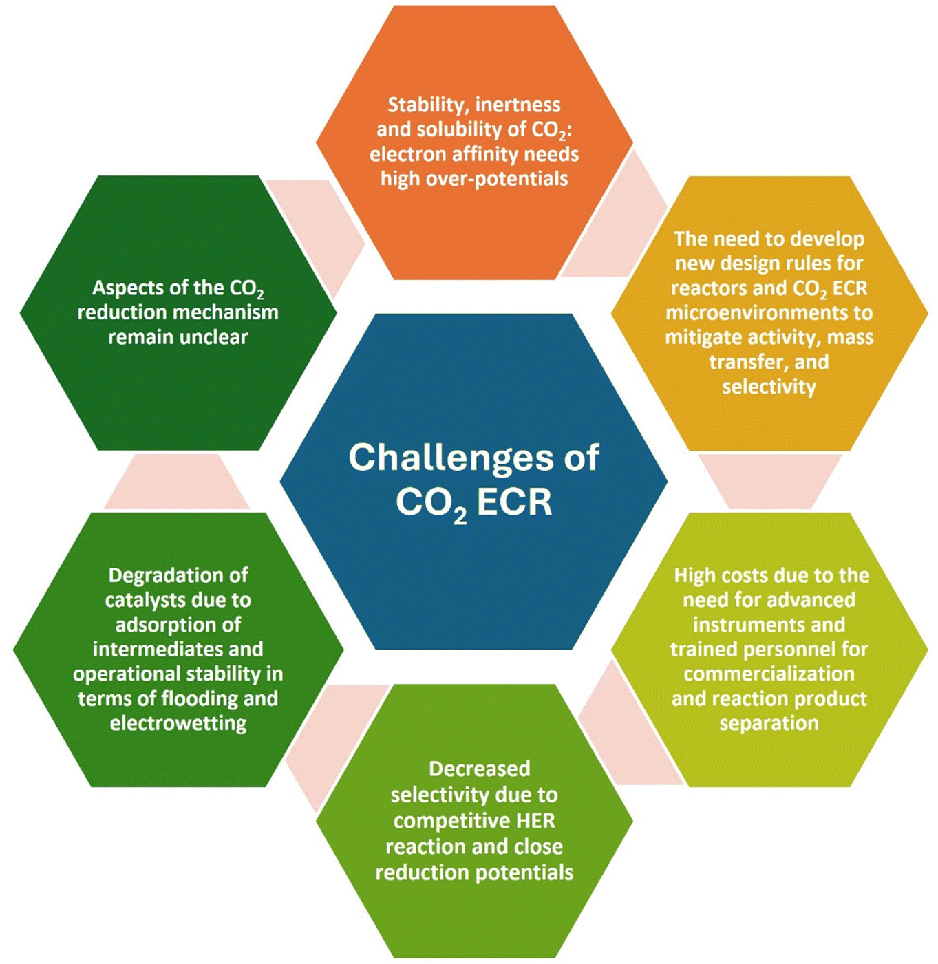 | ||
| Scheme 1 Challenges during the ECR of CO2. | ||
The main challenge in the commercialization of CO2 conversion technology is determining the optimal method for sourcing CO2 as addressing the cost of CO2 capture remains a significant obstacle.130 Many industries that emit CO2 are interested in overcoming its emission but lack the necessary technology to do so. Several challenges arise from this technological gap. For instance, collecting the entire CO2 ecosystem to a site to ensure that its sufficient upstream (CO2 capture) and downstream components (thermochemical and biochemical upgrading) are integrated into a single plant is a challenge. This also adds the challenge of providing internal project management, contract, and contingency professionals to support large-scale commercialization. The site for commercialization is another logistical challenge. CO2 electrolyzers need to be located near areas with large amounts of cheap renewable electricity, and also boundary customer premises for direct integration into downstream processes and avoid the need for constructing new infrastructure/facilities. In some situations where customer areas are not suitable for optimal cost conditions for electrolysis, the implementation of existing pipeline infrastructure can provide an economical method for transporting CO2 or downstream liquid fuels to customers. Despite the above-mentioned challenges, the industry is advised to develop CO2 electrolysis for larger commercial applications. Therefore, through strict regulations on the regions and the impacts of climate change becoming more apparent, this technology is an important means to integrate industrial production in the future.131
2. Extrinsic and intrinsic factors with impacts on activities and products of ECR of CO2
Heterogeneous catalysis is associated with an intensively complex set of scenarios, and to formulate or develop catalyst design strategies, it is necessary to identify the major parameters that are responsible for the catalytic rate and selectivity. As mentioned in the Introduction (see section 1.2), the main purpose of this review is to identify and categorize the potential factors that have a significant impact on the electrocatalytic reduction of CO2. These factors are categorized as extrinsic and intrinsic factors, which are individually discussed in detail below. Table 2 elaborates the fundamental differences in the extrinsic and intrinsic parameters with their features and corresponding impacts on ECR of CO2.| Extrinsic factors | Intrinsic factors | |
|---|---|---|
| Features | - Defined by the relationship of the catalyst with its environment | - Material-specific properties |
| - Sources of electronic and structural effect | - Sources of electronic and structural effect | |
| Dependability on the environment | The extrinsic properties require another material or geometrical structuring, for example, an interface of some type either with another solid material, liquid, or gas to influence the host catalyst | Independent of the surroundings |
| Degree of tunability | Easily to tune and control the parameters | The intrinsic properties can be tuned |
| Impacts on ECR of CO2 | Impacts on activity, stability and selectivity | Impacts on activity, stability and selectivity |
| Selected examples from each factor | Applied voltage, pressure, electrolyte solution (ions, pH and concentration) and temperature | Chemical composition, atomic structure, nature or type of electrocatalyst, surface area & active site |
Scheme 2 aims to systematize the various approaches for overcoming scaling relations. This 2D scheme simplifies a multi-parameter space, where the ordinate represents extrinsic versus intrinsic parameters, and the abscissa reflects the structural versus electronic effects.132 This scheme illustrates the interrelationship between intrinsic and extrinsic parameters, showing that the effect of each parameter can indirectly or directly influence the others. Additionally, the electronic properties/effect also have a significant impact on the structural properties of the electrocatalyst. Therefore, to effectively describe this scenario, we present the interrelated impacts and relationships among all parameters and effects in the diamond-shape scheme.
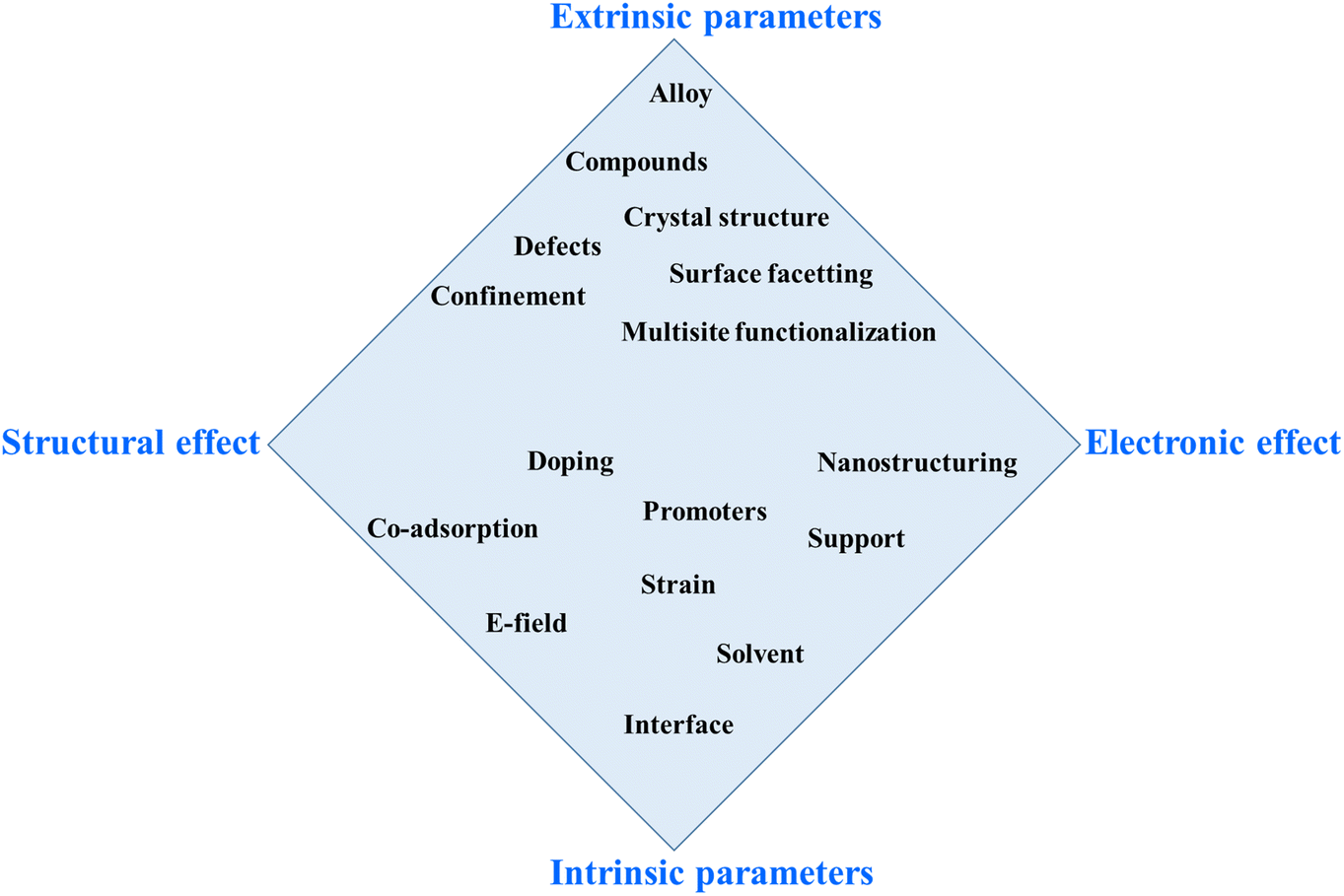 | ||
| Scheme 2 Possible approaches to circumvent the energy scaling relations. The routes are positioned in a space spanned by structural and electronic effects and extrinsic and intrinsic parameters.132 | ||
2.1 Extrinsic factors
The catalytic activities and product distribution of the reduction processes are affected by extrinsic and intrinsic parameters and the reaction conditions, as shown in Fig. 6. These factors can be broadly classified into two categories. The first category consists of the external conditions/factors, which are categorized as extrinsic, including type and concentration of electrolyte, pH of electrolyte, applied potential, pressure of CO2 flow, type of reaction cell, ionomers, hydrophobicity and temperature of the electrolyte solution. | ||
| Fig. 6 Extrinsic and intrinsic factors affecting the ECR of CO2. | ||
2.1.1.1 Impact of cations. Here, we analyze the studies showing that the cation specifications in the electrolyte remarkably affect the selectivity and reaction rates of ECR of CO2. Resasco et al. investigated solid–liquid interface engineering as an emerging and promising technique to optimize the activity and product selectivity.52 Particularly, the cation properties/identity and interfacial electric field have been shown to have a significant impact on the activity for the desired products. Experimental and theoretical studies showed that the cation size and its resultant influence on the interfacial electric field are crucial factors in the ion specificity of ECR of CO2. The abrupt change in the potential between the electrolyte and electrode and the resulting interfacial electric field are the driving force in electrochemical reaction activities. In the case of surface-mediated electrocatalytic reactions, the interfacial electric field is thought to affect the reactivity and stability of the adsorbed intermediates during the reduction process. The effect of an electric field in ECR of CO2 is also discussed together with dangling bonds and strain effect in detail in sub-section 2.2.2. The accurate measurement of the interfacial electric field is a pre-condition in understanding how it impacts the rate and product distribution in electrochemical reactions. The vibrational Stark effect of adsorbates, such as CO, offers an accessible means to assess the interfacial electric field ability by determining the shift in the vibrational peaks of the adsorbates with potential, i.e., the Stark tuning rate. However, the role of the vibrational Stark effect can be convoluted with the dynamical dipole coupling effect of the adsorbates on less binding surfaces such as Cu, complicating the detection/determination of the intrinsic Stark tuning rate. Chang et al. reported an effective strategy for determining the intrinsic Stark tuning rate by removing the impact of the dynamical coupling of adsorbed CO on a Cu surface using surface enhanced infrared absorption spectroscopy.140
Understanding how the cations distribute in the electric double layer (EDL), as shown in Fig. 7A, and their critical effect on the reduction process are important for selecting an appropriate electrolyte solution.141,142 The EDL structure contains an outer Helmholtz plane (OHP) and an inner Helmholtz plane (IHP). In the OHP, ions are not chemisorbed but surrounded by solvent molecules (i.e. solvated), and a diffuse layer extends from the OHP to the bulk of the solution (ions in the diffuse layer are disorderly arranged). In the IHP, ions are specifically adsorbed on the electrode. This scenario indicates that the effect of cations occurs on these two regions of the double-layer.51,141,143–146 The cations in the EDL have been reported to play an important role in different electrocatalytic reactions such as HOR, HER, and ORR. Generally, cations are categorized into multivalent cations, alkali metals and cationic surfactants.
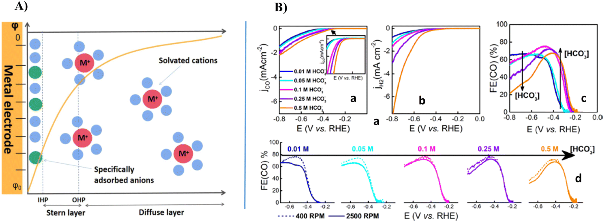 | ||
| Fig. 7 (A) Scheme of electric double layer structure using Gouy–Chapman–Stern model. The green, blue, and red spheres represent anions, solvent molecules, and cations, respectively. (B) (a) ECR of CO2; (b) HER currents; and (c) % FE(CO) in CO2-saturated bicarbonate electrolytes with different concentrations of NaHCO3 and a constant concentration of Na+ (0.5 M), as measured by RRDE voltammetry at 20 mV s−1 and 2500 rpm; and (d) % FE(CO) for different bicarbonate concentrations at 400 and 2500 rpm.141,147,148 | ||
According to the study by Marcandalli et al., as depicted in Fig. 7B, the bicarbonate concentration affects ECR of CO2. Using an RRDE to probe the amount of CO evolved at the disk electrode, they measured the dependence of ECR current (jCO) and HER current (jH2) on bicarbonate. This figure presents the generation of current in ECR of CO2 and HER, respectively, for different bicarbonate concentrations as measured by RRDE at 2500 rpm with the Na+ concentration of 0.5 M. The comparison in Fig. 7B indicates that both ECR of CO2 and HER are favored to a different extent by an increase in bicarbonate concentration. Employing jCO, they calculated the % FE(CO) at 2500 rpm between 0.0 and −0.8 V vs. RHE. They also reported the effect of rotation rate (400 and 2500 rpm) on the % FE(CO) for a specific electrolyte solution.15,137,147,149–151
Alkali metal ions. The effect of alkali metal cations in enhancing the activity and selectivity of ECR of CO2 toward the desired products was first studied by Resasco et al.152 They found that the reduction overpotential for the formation of HCOOH decreased by changing the Li+-containing electrolyte to Na+- or tetraethylammonium-containing electrolytes. Murata et al.153 revealed that the faradaic efficiency of C2+ products was enhanced on polycrystalline Cu, while the selectivity for the HER decreased from Li+ to Cs+. Continuous research showed that the cation increases the reduction activity for CO2 on metal electrocatalysts such as Au, Pb, Ag, Cu and Sn. It was proposed that cation-specific first proposed that cation-specific adsorption alters the potential profile in the EDL according to Frumkin's theory.19 Another opinion on the effect of alkali metal cations on the reduction process is their possible steric hindrance to influence the OHP potential due to the variation in cation size. The variation in the size of hydrated cations has an insignificant impact on the OHP potential for an applied potential higher than −1 V vs. RHE.141,145,148,154–156
Singh et al. proposed that cations can influence the ECR of CO2 by buffering the interfacial pH to maintain a correspondingly high concentration of CO2, which is contrary to the above-mentioned concept.157 They noted that the pH near the cathode increases as the applied cell voltage increases, resulting in a reduction in the amount of dissolved CO2 existing as molecular CO2 in the vicinity of the cathode. This phenomenon is responsible for the increment in the concentration of HCO3− and CO3−, leading to the selective reduction of CO2 towards C2+ and hydrocarbons. For instance, A. Schizodimou et al. reported that the rate of the reduction using a CuSnPb alloy electrode in the presence of La3+ is two times higher than that of solutions containing Na+ under the same potential and reduction conditions.158 Moreover, the % FE for CH3OH increased from 17.8% to 35.7% in the presence of La3+. In the presence of Zr4+, the % FE for CH3CHO increased significantly compared to the electrolyte solutions containing monovalent cations such as Na+. According to the DFT calculations reported by Ringe et al., the existence of multivalent cations such as Be2+, Al3+, Ba2+, and La3+ resulted in two orders of magnitude higher reduction activity on Ag(111) at −1 V vs. RHE.17,52,141,159,160
Therefore, it can be summarized that alkali metal cations, cationic surfactants, and multivalent cations play a role in modifying the electrode–electrolyte interface in the EDL. They can influence both the selectivity and activity of the electrochemical reduction of CO2 in the following ways:141
a) Controlling the pH gradient near the electrode, and hence affecting the local CO2 concentration by buffering the interfacial pH.
b) Establishing and modifying the interfacial electric field to stabilize certain reaction intermediates with large dipole moments.
c) Determining the HER activity by tuning the H+ concentration near the electrode via electrostatic interactions.
In contrast to the effect of alkali cations, some studies141 investigated amphiphilic surfactants, which consist of long alkyl chains with a polar head group that can enhance the performance of ECR of CO2 by suppressing the competitive HER. Besides alkali cations and cationic surfactants, the presence of multivalent cations in the electrolyte solution has an impact on the reduction activity.141,148
The cation has a significant impact on the products of electrocatalytic reactions such as oxidation of alcohols, oxidation of formate, HER, OER, and ORR. Studies revealed that the cation identity and the interfacial electric field play a particularly significant role in the activity for ECR of CO2 to obtain the of desired products.52 Potassium bicarbonate (KHCO3) is commonly applied as an electrolyte due to the established equilibrium between CO2 and carbonate–water, which maintains the neutral bulk pH. Hydrated cations are expected to act as proton donors and can alter the pH of the electrode by shifting in local potential at the OHP or by acting as a buffer close to the electrode. It has been suggested that cation adsorbate interactions occur through non-covalent chemical interactions. The effect of alkali cations in ECR of CO2 arises from chemisorbed ions. However, another study noted that alkali ion adsorption including charge transfer is unlikely due to its very negative reduction potential (approximately −3 V vs. RHE).133,145,152 Ringe et al.52 revealed that cations affect the reduction activity through their electrostatic interactions with the electric dipole of specific adsorbates. They built on their studies, employing a mean-field electrostatic approach and analyzing the electrolyte distribution with a modified Poisson–Boltzmann model. They found that the surface charge density and electric field are reduced by the ion-size-dependent hydrated cation repulsions at the OHP. They conducted surface charge-dependent DFT calculations of reaction intermediates to relate the ion-specific surface charge to differences in electrocatalytic activity.52
2.1.1.2 Impact of anions. Both concentration and identity of the anions present in the electrolyte solution influence the ECR of CO2. Therefore, it is important to understand how their effect appears and to what extent their impact has on the reduction activity. Resasco et al.152 experimentally and computationally studied the role of the electrolyte anions in the reduction of CO2 on Cu surfaces. Their practical investigations were conducted to show the effects of bicarbonate buffer concentration and the composition of other buffering anions. The effect is shown in the current and major products generated during the reduction on the Cu electrocatalyst. Their study showed that the composition and concentration of electrolyte anions have a relatively very low impact on the formation of CO, HCOOH, C2H4, and CH3CH2OH. However, the concentration of anions has a significant effect on the formation of CH4 and H2. Other studies15,136,142,150,153,161 also investigated the effect of anions and cations present in the electrolyte.
An ion plays a great role in altering the pH value and the reduction activity on the Cu surface towards the formation of CH4 and H2. However, this phenomenon is insignificant at the nearest electrode surface and results in minor differences in the activity and product selectivity due to changes in the concentration of ions. Thus, Resasco et al. formulated that pH differences are the result of the tendency of buffering anions to donate hydrogen directly to the electrode surface and in competition with the water redox reaction. The efficiency of buffering anions to serve as hydrogen donors increases with a decrease in the pKa of the buffering anion. Hori et al. reported that non-buffering anions (Cl−, ClO4−, and SO42−) result in high selectivity for C2H4 and CH3CH2OH, but lower selectivity for CH4 compared to bicarbonate anions (HCO3−), whereas phosphate anions (H2PO4−) result in a higher selectivity towards CH4.162 The reported study examined the impact of bicarbonate concentration and discovered that a higher ion concentration leads to increased methane production and hydrogen evolution.161,163,164 This group showed (Fig. 8A–F) the effect of bicarbonate ions on the partial current density and major product in the reduction process.15
 | ||
| Fig. 8 (A–F) Impact of HCO3− buffer concentration on the production of main products and generation of partial current for each of major products in ECR of CO2 on Cu(100). The current density for each product is represented as a function of the bicarbonate buffer concentration in the electrolyte solution in the range of −0.7 and −1.0 V vs. RHE. Reproduced with permission.15 ©2018, Wiley-VCH Verlag GmbH & Co. KGaA, Weinheim. | ||
This group has concluded that the concentration and composition of the electrolyte anions have a relatively minor effect on the formation of HCOOOH, C2H4, CO and CH3CH2OH. This finding is attributed to the fact that the rate-limiting step for the generation of each of these products does not involve the addition of hydrogen atoms. This process can be thought of as the concerted transfer of a proton and electron or the reaction of a water molecule and an electron with the release of a hydroxyl anion. In contrast, the formation of H2 and CH4 exhibits strong sensitivity to the composition and concentration of ions in the electrolyte solution.15
2.1.1.3 Impact of halide ions. Similar to other ions, the presence of halides in the electrolyte solution can also affect the catalytic activity and performance of ECR of CO2. Ma et al. studied and reported the presence of halide anions in the electrolyte to improve the % FE for the multi-hydrocarbon (C2+) products for the electrochemical reduction of CO2 on the surface of Cu electrocatalysts. However, the underlying mechanism for the increment in C2+ products with the addition of halide anions is still unclear. This group studied the mechanism by computing the relative free energies and investigating the electronic structures of the intermediates formed from CO2 to C2H4 on the Cu(100) facet based on DFT calculations. The results indicate that formyl *CHO from the hydrogenation reaction of the adsorbed *CO acts as the key intermediate, and the C–C coupling reaction occurs preferentially between *CHO and *CO with the formation of a *CHO–CO intermediate. Then, they proposed the free-energy pathway for C2H4 formation. This group found that the presence of halide anions significantly decreases the free energy of the *CHOCH intermediate and increases the desorption of C2H4 in the order of I− > Cl− > Br− > F−. The DFT calculations performed by this group focused on the CO* coupling for the formation of multiple carbon products (C2+), as shown in Fig. 9.152,157,165
 | ||
| Fig. 9 (A) Calculated relative free energy (ΔG) of three reaction pathways from *CO to C–C bond formation on Cu(100) facet without halide ions at U = 0 V (vs. RHE) and T = 298.15 K. The energy unit is eV. (B) Optimized structures of key intermediates. The distance unit is Å. Color legend: Cu blue, O red, C brown, and H pink. Reproduced with permission.165 ©2022, Wiley-VCH GmbH. | ||
According to the DFT calculations, the ΔG for the dimerization of surface-adsorbed *CO to form *COCO in pathway I is 1.09 eV, while the ΔG for further hydrogenation to *CHOCO is −0.30 eV.15,166 In pathway II, the adsorbed *CO on the Cu(100) facet is first converted to formyl *CHO through the proton–electron transfer, which is an endothermic process with a calculated ΔG of 0.67 eV. Afterwards, *CHO couples with *CO, leading to the formation of *CHOCO, and ΔG is 0.12 eV for this step. In pathway III, the adsorbed *CO also reacts with the proton–electron transfer but forms *COH with a higher reaction-free energy (0.96 eV).126,158,165 Then, *COH reacts with *CO and forms *COHCO, requiring an energy of 0.17 eV. In conclusion, pathway II is the most energetically favorable owing to its lowest free energy of 0.67 eV, that is, *CO is firstly hydrogenated to form *CHO, and further couples with an incoming *CO with the help of the halide ions present in the electrolyte solution.9,79,117
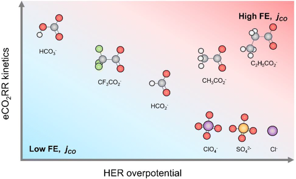
Yoo et al. reported a systematic investigation of the anion-dependent selectivity and activity in ECR of CO2 on gold catalysts using in situ differential electrochemical mass spectrometry (DEMS) employing a wide range of anions. Their results showed that by replacing HCO3− with carboxylate anions, HER is significantly suppressed. Additionally, they revealed that propionate and acetate can promote ECR of CO2 comparable with HCO3− unlike the other studied anions, which display a largely increased overpotential for ECR of CO2. Specifically, propionate benefits from both the suppressed HER and kinetics comparable to HCO3−, reaching an impressive FE% close to 100%, while displaying high CO production rates that are comparable to bicarbonate. These insights underscore the vital role of anion selection in achieving highly efficient ECR of CO2 in aqueous electrolytes. This group compared the selectivity and activity of ECR of CO2 on an Au electrocatalyst in different electrolytes with different anions including perchlorate, bicarbonate, sulfate, carboxylates and chloride. A potassium salt was selected due to its promoting role in the reduction process.152,167 Propionate (C2H5COO−), trifluoroacetate (CF3COO−), acetate (CH3COO−) and formate (HCOO−) were selected as representative carboxylate anions owing to their structural closeness to bicarbonate. The testing configuration (e.g. mass transfer of electrolyte) can affect the absolute values of activity and selectivity in the reduction of CO2.30,147,168 Specifically, to gain real-time insights into the activity, selectivity and reaction kinetics,30 they employed a DEMS approach for operando monitoring of the products. Consequently, they obtained the production rates of both H2 and CO molecules on the Au catalyst surface as a function of potential and selected anion.142
Another group studied the effect of anions on the HER kinetics on polycrystalline Au using rotating-disk electrode (RDE) for 3 different inorganic anions (i.e., perchlorate, sulfate and chloride) and benchmarked them against bicarbonate. In all cases, the potassium (K+) cation concentration was set at 0.1 M.152,167 Similar HER current densities were detected for all the anions, except bicarbonate for which much larger HER activity was measured (Fig. 10A). They further corroborated the bicarbonate-driven HER by conducting additional experiments in perchlorate–bicarbonate mixtures at different ratios, while maintaining [K+] = 0.1 M (Fig. 10B). By increasing the molar fraction of bicarbonate, lower HER overpotentials and thereby higher HER activities were obtained (Fig. 10C). This group found that the HER activity trend was similar to that of the Ar-saturated electrolyte case, where the HER currents were significantly higher in bicarbonate electrolytes compared to other anions (Fig. 10D). Concurrently, the CO2-to-CO conversion is characterized by an earlier onset potential in bicarbonate (Eonset = −0.30 V vs. RHE) than other anions (Eonset ≈ −0.5 V vs. RHE) (Fig. 10E), indicating more favorable reduction kinetics in the presence of bicarbonate compared to perchlorate, sulfate, and chloride electrolytes. Eventually, they compared the % FE for CO2-to-CO conversion as a function of applied potential and anion type (Fig. 10F).
 | ||
| Fig. 10 LSV for hydrogen evolution on polycrystalline Au catalyst in Ar-saturated K+-based electrolytes: (A) bicarbonate, perchlorate, sulfate, and chloride anions and (B) mixture of bicarbonate and perchlorate anions. (C) Hydrogen evolution overpotential at current density j = −2 mA cm−2, (D) hydrogen evolution and ECR of CO2 partial current density on Au thin-film catalyst in CO2-saturated electrolytes, (F) faradaic efficiency for ECR of CO2 in each carboxylate electrolyte and (E) effect of electrolyte type in terms of current density.142 | ||
Yoo et al.133,142 also investigated the fact that carboxylate anions show structural similarity to the HCO3− anion with a negatively charged carboxyl group. Consequently, they can significantly participate in the stabilization of the ECR of CO2 intermediates, but thus far there have been no reports on the use of carboxylate-based electrolytes for the electrocatalytic reduction. This research group studied the ECR of CO2 activity and selectivity in propionate, acetate, trifluoroacetate, and formate. Each of these anions showed a different electron density on the carboxylic acid group, and thereby characterized by distinct pKa values. They emphasized the crucial role of anions in maximizing the CO2 reduction and controlling HER by electrolyte engineering for advanced electrochemical CO2 conversion systems.142
Studies reported that bicarbonate is highly important for the ECR of CO2, and at the same time it promotes HER (from bicarbonate), as shown in Fig. 11. Consequently, it can decrease the selectivity of ECR of CO2, especially at a higher overpotential (beyond −0.6 V vs. RHE). Replacing bicarbonates with perchlorate, sulfate, or chloride largely suppresses the current generated by HER, leading to a significant increase in the FE% at potentials below E = −0.8 V (vs. RHE). The lack of bicarbonate also causes a significant decrease in the reduction activity. Another scenario involves carboxylate anions, where on the whole, the HER is primarily suppressed by excluding bicarbonate-related HER, whereas the efficiency and selectivity of the electrochemical reduction of CO2 vary depending on the type of carboxylate, with the highest values observed in the case of propionate. As a result, both high activity and selectivity were achieved in 0.1 M C2H5COOK electrolyte, overcoming the characteristic limitations of electrolytes with bicarbonate or salts of conventional inorganic anions.142
 | ||
| Fig. 11 Effect of electrolyte anions on ECR of CO2 and hydrogen evolution reaction.142 | ||
The use of ionomers in fabricating catalytic electrodes showed a significant effect on their catalytic activity and product selectivity, particularly for Cu-catalyzed multicarbon (C2+) product formation. Zeng et al. reported the performance of ECR of CO2 using Cu catalysts coated with 8 different commercial ionomers to determine how ionomers influence the formation of the C2+ product in zero-gap membrane electrode assembly (MEA) reactors. They found that the ionomer hydrophobicity plays the most crucial role in determining the FE% and partial current density of C2+ products. Cu coated with the most hydrophobic ionomer reduced CO2 into C2+ products by generating 180 mA cm−2 and FE of about 75%. This was attributed to the hydrophobicity-induced *CO adsorption stabilization. This result also demonstrated that the ionized side chains of ionomers possibly have an impact on the activity and selectivity of the C2+ products by changing the electric double layer (EDL) structures. Ionized side chains with bulkier molecular structures and smaller hydration numbers likely lead to less compact EDLs, enhancing the C–C coupling process.175
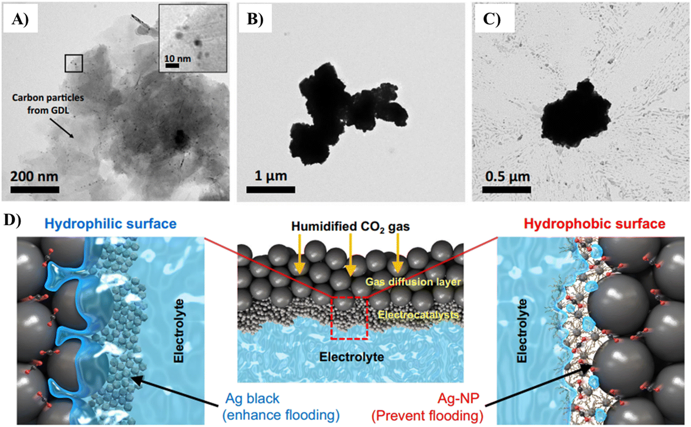 | ||
| Fig. 12 Low-magnification TEM image of (A) Ag-NP, (B) Ag black, (C) and Ag-PTFE catalysts after the durability test at 3.4 V vs. RHE. (D) Schematic (low and high magnifications) of the triple-phase boundary for the hydrophilic Ag black and hydrophobic Ag-NP catalysts in the CO2 electrolyzer.176 | ||
The submerged hydrophobic electrocatalyst surface traps sufficient gas at the nanoscale level. This also occurs at the microscale if the Cassie–Baxter state is reached, which can allow gaseous CO2 to accumulate at the Cu–solution interface.178–181 Many reports investigated gas–electrode–solution i.e. triple-phase boundaries to enhance the activity of CO2 reduction using Cu on GDEs with hydrophobic polytetrafluoroethylene layers. However, it is difficult to remark if this enhancement is solely owing to hydrophobicity over other factors such as porosity and enhancement of mass transport of CO2.182,183
David et al. studied hydrophobicity as a significant parameter on a Cu surface to establish its role in enhancing gas trapping, and then promoting the selectivity for CO2 reduction. Interestingly and appreciably, they introduced hydrophobicity based on the ‘plastron effect’ utilized by aquatic arachnids, such as the diving bell spider (Fig. 13A). These plastrons consist of hydrophobic hairs that can trap air and allow the spider to respire underwater. The gas-trapping situation is carried out when hydrophobicity occurs simultaneously on the microscale and nanoscale surface structure. This research group attained an analogous multiscale hydrophobic surface via the modification of hierarchically structured dendritic Cu with a monolayer of waxy alkanethiol. The final electrode visibly trapped CO2 at the electrolyte–electrode interface to produce a triple-phase boundary (Fig. 13B). Consequently, HER on this surface was significantly minimized in CO2-saturated electrolyte than its unmodified hydrophilic equivalent from 71% FE to 10%. Alternatively, the FE% for CO2 reduction increased from 24% to 86%, among which 74% was towards the formation of C2 products. Specifically, they also reported that the hydrophobic electrode achieved an FE of 56% for C2H4 and 17% for C2H5OH formation at neutral pH compared to that of 9% and 4% on a hydrophilic, wettable equivalent, respectively. These results were assigned to the trapped gases at the hydrophobic Cu surface, which enhanced the level of CO2 at the electrode–solution interface, and thus increased the selectivity for CO2 reduction. Therefore, hydrophobicity is proposed as a determinant parameter or factor in the selectivity for ECR of CO2, which can help describe the trends observed on previously studied electrocatalysts.178,184,185
 | ||
| Fig. 13 (A) Diving bell spider for subaquatic breathing in and (B) on a hydrophobic dendritic cu surface for aqueous CO2 reduction.178 | ||
Buckley et al. investigated oxide-derived Cu (Cu-OD) electrocatalysts modified using protic or aprotic functional groups (hydrophobic nature). The authors proposed a relationship between hydrophobicity and product selectivity, indicating the presence of H+/H2O on the metal–ligand interface of the Cu surface.171 In another study, the preparation of Ag–Cu nanodimers (25 nm) with a hexadecylamine ligand (hydrophobic property) was carried out. The synthesized hydrophobic nanodimer showed a good performance in ECR of CO2. However, the possible impact of the ligand on the selectivity for CO2 reduction was not reported.186 Another study revealed the impact of the incorporated ligand on the ECR of CO2 activity. The treatment of the ligand on the Ag-NP electrocatalyst resulted in a change in the activity for the formation of CO.177 In the above-mentioned studies, the utilization of ligands during colloidal preparation may affect the local environment of the active sites for ECR of CO2. This is because the hydrophobic ligand tends to limit or restrict not only the physical but also the electrical contact between the substrate and individual particles. Irtem et al. prepared a Cu–Ag core–shell nanoparticle electrocatalyst with a particle size of ∼11 nm for ECR of CO2. They prepared three different surface modes, as follows: (a) capped with monoisopropylamine (MIPA), (b) capped with oleylamine (OAm), and (c) surfactant-free with a reducing borohydride agent (NaBH4). Their experimental results showed that among the three modes, Cu–Ag (OAm) gave the lowest onset potential for the formation of hydrocarbon, whereas Cu–Ag (NaBH4) and Cu–Ag (MIPA) enhanced the production of syngas (CH4 and C2H4). The surface area and electrochemical impedance measurement on the well-controlled electrodes indicated a gradual increase in the electrical conductivity and active surface area after the treatment of each surface using MIPA, NaBH4 and OAm. The authors found and recommended that increasing the amount of triple phase boundaries i.e. electrolyte–meeting point for electrons–CO2 reactant influences the required electrode overpotential, and eventually the product distribution.122 Their investigation overviews the necessity of the electron transfer to the active sites influenced by the capping agents specifically on larger substrates, which will play a key role in the commercialization process.
Monteiro et al. studied the effect of catalyst loading on the activity and selectivity for ECR of CO2. They utilized shear-force-based Au nanoelectrode positioning and scanning electrochemical microscopy (SECM) in the surface generation tip collection mode to measure/evaluate the activity of Au GDEs for the reduction of CO2 as a function of catalyst loading and back pressure of CO2. Using an Au nanoelectrode, they locally quantified the amount of CO generated along a catalyst loading gradient via operando conditions. It was observed and understood that an appropriate and optimum local loading of electrocatalyst is required to attain high activity and selectivity. However, this optimum catalyst loading is directly related and dependent on the CO2 back pressure. This work not only provides a tool to analyze the activity of GDEs locally, but it also directs drawing a more precise picture concerning the impact of catalyst loading and back pressure of CO2 on the reduction performance.120
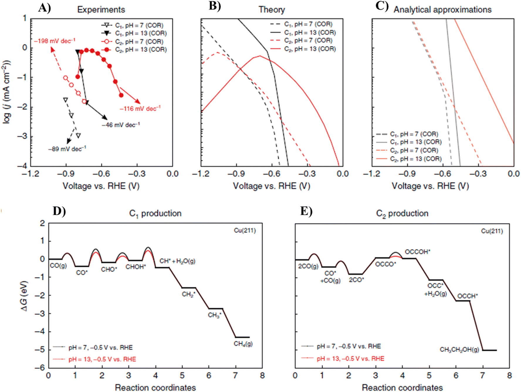
The theoretical result was consistent with the experimental findings191,192 such as the depletion of C2 product activity at a high overpotential, differences in the Tafel slopes between the C2 and C1 products at a low overpotential, similarities in the CO2 and CO reduction activity, and the dramatic impact of pH on the C2 and C1 product activity and selectivity. They found that the differences in the pH dependence between the C1 and C2 paths arise from the differences in their rate-determining proton–electron transfer steps with water as the proton source. This group also showed that given the facile kinetics for CO2 conversion to CO on Cu, there is minor difference between the reduction activities of CO and CO2. The original mechanistic insights supplied in their work revealed how the reaction conditions can lead to significant enhancements in selectivity and activity of ECR of CO2 toward C2 products. Furthermore, the differences in the rate-limiting steps for C1 and C2 production also induce differences in pH dependence.47
As shown in Fig. 14A, Liu et al. also recorded the experimental polarization curves for the CO reduction reaction in the bulk at a pH of 7 and 13, respectively. Fig. 14B and C reveal the corresponding predictions from micro-kinetic modeling and the analytical approximation, respectively. It was found that the analytical approximation can give qualitatively good agreement with experiments in the low overpotential range, resulting in consistent Tafel slopes and shifts in the overpotential with a change in pH. The competing pathways present in the micro-kinetic model also give rise to its lower simulated rates vs. the analytical formulation. This is because the intermediate coverages are lower given that they are consumed by multiple pathways. The experimental and theoretical pictures together show that the electrolyte pH can be tuned to favor the activity and selectivity toward more C2+ products. The shift of around 0.36 V in the overpotential for C2 products between pH 7 and 13 translates to over three orders of magnitude enhancement in C2 activity. The lower shift in C1 products translates to a tremendous enhancement in C2 selectivity (1–2 order(s) of magnitude). It should be noted that their model predicted a similar depletion in C2 products at high overpotentials at pH 7 as in pH 13 for the same reasons, though to date no experimental data exist for pH 7 at such high overpotentials. It has been suggested both experimentally72 and theoretically87 that the formation of CO* from CO2(g) is relatively facile on copper. Therefore, ECR of CO2 and CO should display similar kinetics if operated at the same environmental pH.47
 | ||
| Fig. 14 Effect of pH on C1 and C2 product activities. (A) Measured COR activities toward C1 and C2 on pc-Cu at pH = 7 and 13. Data are taken from Wang et al.26,47,91 (B) Predicted COR polarization curves from the micro-kinetic model at pH = 7 and pH = 13. (C) Approximated COR polarization curves using eqn (4) at pH = 7 and pH = 13. (D) Free energy diagram of the dominant pathway at low coverage for C1 formation at −0.5 V vs. RHE at pH = 7 and pH = 13. (E) Free energy diagram of the dominant pathway at low coverage for C2 formation at −0.5 V vs. RHE at pH = 7 and pH = 13.47 | ||
Liu et al. summarized a detailed micro-kinetic model of CO2 reduction on Cu(211) surfaces toward the formation of C1 and C2 products. The simulation activities showed a qualitative and even semi-quantitative agreement with experimental observations, and it was shown that the distinctive potential dependence (Tafel slope and pH effects) of C1 and C2 formation can be rationalized through differences in their rate-limiting steps. C2 production at low overpotentials is limited by the rate of the first proton–electron transfer to the OCCO* intermediate, resulting in a conventional SHE-scale dependence, while at high overpotentials, it is limited by CO coverage. Alternatively, C1 formation is limited by a later proton–electron transfer to the CHOH* intermediate at a low overpotential, in contrast to previous studies, which focus on the protonation of CO*. Consequently, it exhibits a much higher Tafel slope and a smaller enhancement in activity with an increase in pH. This group demonstrated that ECR of CO2 and CO shows similar kinetics within the potential range of interest.47 The mechanistic insights supplied in this work provide ways to tune the activity and selectivity toward higher-value C2 products, which has major implications for the design of industrial-scale ECR of CO2.47
Marcandalli et al. reported that the current due to ECR of CO2 towards CO exhibits little pH dependence and zero-reaction order in proton donors for both bicarbonate147,193 and water.194,195 This independence of the ECR of CO2 rate on the concentration of proton donor together with a Tafel slope value of 120 mV dec−1 was interpreted as the first electron transfer (CO2 + e− + * → *CO2) being the RDS.193,194 The proton donor can be any acid (AH), strong or weak, present in the solution.15,147,196 Hence, we refer to AH as the proton source leading to HER according to the following reaction (1):133
| 2AH + 2e− ↔ H2 + 2A− | (1) |
 | ||
| Fig. 15 (A) Faradaic efficiency for CO and (B) partial current density of CO as a function of cell potential for 3 different pH levels and two different CO2 concentrations (10 and 100%). Comparison of ECR of CO2 and CO at pH 7: (C) measured CO and CO2 reduction activities toward C1 and C2 at pH = 7 and (D) theoretically predicted polarization curves of ECR of CO2 and CO on Cu(211) at pH = 7.197 | ||
Xinyan et al. studied the effect of pH on ECR of CO2 by comparing theoretical predictions and experimental results. According to their study, as shown in Fig. 15C and D, the experimental and theoretical pictures together reveal that the electrolyte pH can be employed to bias the activity and selectivity toward the formation of C2+ products. The overpotential shift of ∼0.36 V for C2 products in the pH range 7–13 translates to over three orders of magnitude increase in C2 activity. The smaller shift in C1 products translates to a significant enhancement in C2 selectivity by approximately two orders of magnitude. This group suggested that their model indicates a similar depletion in C2 products at a large overpotential at pH 7 as pH 13 for the same reasons, though no experimental data exist for pH 7 to date at such high overpotentials in ECR of CO2.47,70,136
Vos et al.204 investigated the effect of reaction temperature on the product distribution and activity of ECR of CO2 on a copper electrocatalyst. In this study, they conducted the electrolysis experiments at different applied potentials and reaction temperatures within two distinct temperature regimes. In the temperature range of 18–48 °C, C2+ products were significantly produced with higher % FE, while the selectivity for methane and formic acid decreased and the selectivity for hydrogen remained approximately constant. In the temperature range of 48 °C to 70 °C, they found that HER was dominant and the activity for ECR of CO2 decreased. Additionally, in the higher temperature range, the reduction products were mainly the C1 products, i.e., HCOOH and CO. This group argued that the local pH, CO surface coverage, and kinetics all play a crucial role in the lower-temperature range, while the second regime appears most likely to be related to the structural changes in the copper surface.200,203,205
Vos et al.204 showed the effect of reaction temperature on the product distribution of ECR of CO2 using a copper surface as the electrocatalyst. Fig. 16 shows the effect of reaction temperature on the product distribution on the copper surface. They also reported the % FE toward the most important products between 18 °C and 70 °C at −1.1 V vs. RHE in dark circles.
 | ||
| Fig. 16 Faradaic efficiency (in dark circles) and partial current density (in light squares) during ECR of CO2 at different reaction temperatures in 0.1 M KHCO3 at −1.1 V vs. RHE for (A) hydrogen, (B) CO, (C) methane, (D) formic acid, (E) ethylene, (F) ethanol, and (G) 1-propanol. The error bars are determined from at least 3 separate experiments. The gray background indicates the second regime, and the dotted lines are a guide to the eye.205 | ||
According to the data reported by this research group, as shown in Fig. 17, the total current density increased with an increase in temperature, even if tgaqciecan be calculated from the polarizatnsity decreased slightly in the range of 48 °C to 62 °C due to the fast decrease in CO2 reduction activity, after which HER took over and the total current density increased rapidly at higher temperatures. The total current, CO2 consumption rate and% carbon efficiency values as a function of temperature are revealed in Fig. 17A–C, respectively.205
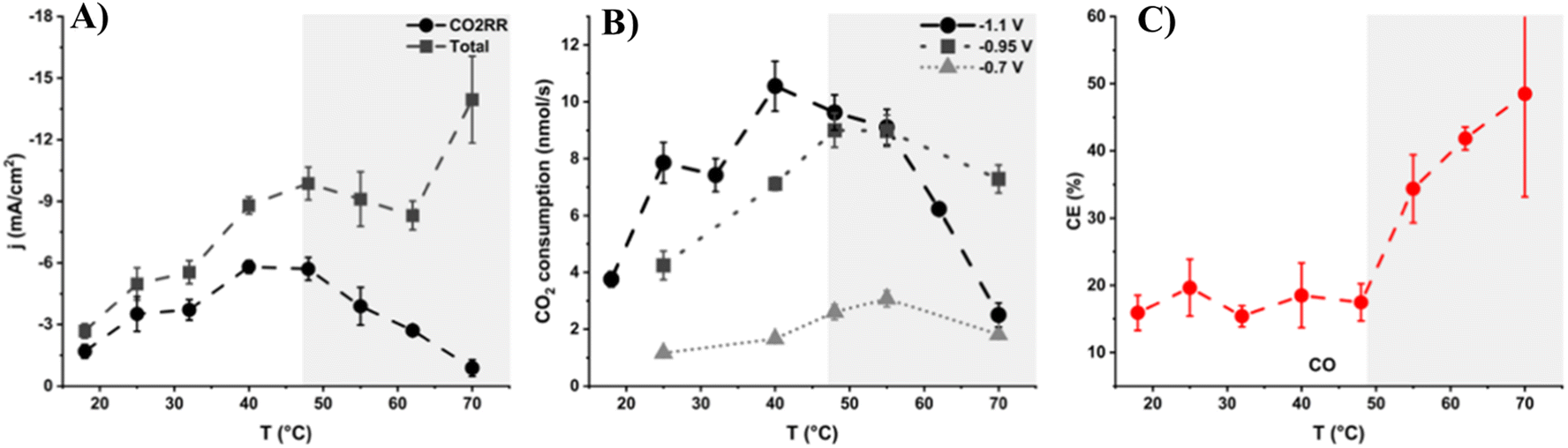 | ||
| Fig. 17 (A) Total current density and current density toward ECR of CO2 at −1.1 V vs. RHE, (B) total consumption of CO2 during the reduction at different reaction temperatures in 0.1 M KHCO3 at −1.1, −0.9, and −0.7 V vs. RHE, and (C) carbon efficiency toward CO at −1.1 V vs. RHE.205 | ||
In another report by Vos et al.,204 they investigated the impact of temperature on a simple ECR of CO2 system using gold as the electrocatalyst. They have found that on the gold electrocatalyst, it is preferable to conduct the reduction at high temperatures, which enhanced the selectivity and activity toward CO. However, mass transport becomes more important at elevated temperatures and at a certain point, the availability of CO2 becomes the limiting factor in the reaction. At temperatures higher than 55 °C, they observed a plateau in the reduction activity. Fig. 18A and B show the effect of temperature on the activity of ECR of CO2 and hydrogen evolution on the gold electrode. The partial current density for CO increased with an increase in temperature up to 50–55 °C.
 | ||
| Fig. 18 Partial current density towards CO formation (A) and H2 (B) at different temperatures in 0.1 M NaHCO3 on a gold RRDE at 2500 rpm and 20 mV s−1.205 Curves (the fifth cycle) of Pt in N2 (C) and CO2-saturated, a (−2 to 2 V), (D) ionic liquid in the potential range of −3.1 to 1.7 V vs. Ag/AgCl, a′ (−2.5 to 2 V). Reproduced with permission.206 ©2020, the American Chemical Society. | ||
Because of the different thermodynamics, the activity and selectivity in ECR of CO2 and HER are influenced by the reaction temperature and other conditions. Particularly, the reaction temperature has a crucial effect on the selectivity and product distribution of the CO2 reduction process. Thus, it is vital to thoroughly examine the specific connection between the reduction temperature and the reduction selectivity and activity. Early in 1986, Hori et al. reported the change in the products in ECR of CO2 on a copper electrode in the range of 0 °C to 40 °C. They indicated that the % FE of the reduction activity towards the formation of CH4 was about 65% at 0 °C. However, this value (% FE for CH4) decreased with an increase in temperature, while the % FE for C2H4 formation increased to 20% at 40 °C.207 Zhan et al. studied the effect of temperature on the reaction path of ECR of CO2. Their results showed that temperature can be used to regulate the reaction pathway of ECR of CO2 in an imidazolium-based ionic liquid through its effects on (a) the adsorption and solubility of the intermediates species; (b) the mass transport of the reactant and intermediates, and (c) the ionic liquid–electrode interface structure and properties. This group investigated the effects of temperature by analyzing the cyclic voltammetry (CV) curves in an N2-saturated ionic liquid by extending the cathodic potential limit up to −3.1 V vs. Ad/AgCl at various temperatures in the range of −10 °C to 40 °C. Fig. 18C and D clearly show the effect of temperature on the ECR of CO2 in N2- and CO2-saturated solution, respectively. At higher temperatures, tgaqciecan be calculated from the polarizatnsity for the reduction in both cases also increased. The maximum current was recorded at 40 °C compared to 25 °C, 0 °C, −5 °C and −10 °C.206
Lobaccaro et al.146 studied the effect of electrolyte temperature through an in situ heating system on the electrochemical reduction process. In situ heating of the H-cell is expected to drive the reaction at both the cathode and anode at the specified potential. As the electrolyte temperature in the H-cell increases, the solubility of CO2 will decrease, which can affect its kinetics and the reaction selectivity. Despite the various research efforts on ECR of CO2, reports on the impact of the temperature are rare. Higher operating temperatures lead to higher currents, and the trends in selectivity are more complex due to the generation of a high amount of hydrogen from HER.146,198,204,205 Most researchers revealed an optimum value of % FE at low temperatures i.e. between 0 °C and 35 °C, as shown in Fig. 19A. When the temperature increases, the solubility of CO2 decreases, resulting in predominantly HER occurring. In contrast to CO2 solubility, the diffusion coefficient increases with temperature, which leads to the highest performance at the optimum temperature. Fig. 19B illustrates the effect of temperature on solution pH and dissolved CO2 concentration in 0.1 M NaHCO3 buffer solution at 1 atm. The temperature slightly changed the bulk electrolyte pH for only a 5 °C shift in electrolyte temperature, while the concentration of dissolved CO2 changed by more than 10%.
 | ||
| Fig. 19 (A) Dependence of CO2 solubility (S) in 2 M aqueous NaCl solution (triangles, black: red) and CO2 diffusion coefficient in water (circles, blue, green) temperature effect on electrolyte,200 (B) effect of temperature on the equilibrium pH (black) and equilibrium dissolved CO2 concentration (red) obtained for a 0.1 M NaHCO3 electrolyte in equilibrium with 1 atm of CO2. The far right hand axis (blue) shows the dissolved CO2 concentration normalized to the value for 25 °C. Reproduced with permission.146 ©The Royal Society of Chemistry. | ||
The study performed by Scialdone et al. revealed the impact of pressure and temperature on the formation of formate in ECR of CO2. The results showed that an increase in pressure promotes the formate formation, but when the temperature increases, this was inhibited. Although an increase in temperature speeds up the reduction kinetics and diffusivity of CO2, it decreases the solubility of CO2, enhancing the competing hydrogen evolution reaction.146,208 The effect of temperature on the % FE of the products, turnover frequency of CO in the reduction, and possible reduction mechanism/scheme was investigated by Hu et al. in 2024, as shown in Fig. 20.51,209
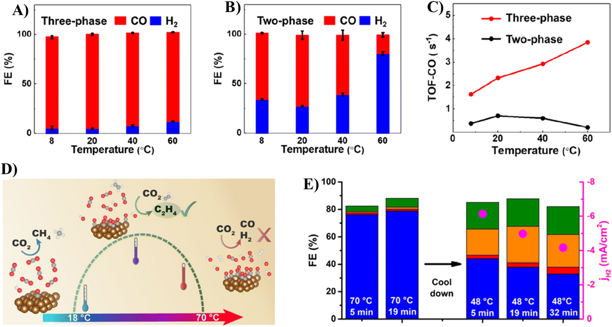 | ||
| Fig. 20 (A and B) % FE for ECR of CO2 evaluated at a potential of −0.7 V and different temperatures. (C) TOFs of CO production at a potential of −0.7 V. (D) Mechanisms for the selective changes in temperature-dependent products. (E) Comparison of the gaseous product % FE in ECR of CO2 at 1.1 V with RHE at 70 °C after 5 and 19 min, and after cooling at 48 °C for 5, 19, and 32 min. The current density of the HER is indicated by the red dots (at 70 °C).51,204 | ||
According to the studies by Hu et al.,51 the impact of pressure on the generation of current density, % FE, product selectivity and utilization of energy in ECR of CO2 is demonstrated in Fig. 21. This group revealed that a higher *CO coverage on the copper surface at higher CO2 pressures could effectively promote the selective production of CH3CH2OH compared with CH2CH2. Measurements in a high-pressure electrolyzer (higher CO2 pressures) with a proton exchange membrane barrier indicated that presence of high *CO coverage on the surface of the Cu2O@Cu hollow sphere (Fig. 21A).14,51 The major C2+ product of the hollow sphere catalyst under high-pressure conditions could be converted from CH2CH2 at ambient pressure to CH3CH2OH, with a conversion rate/efficiency of CH3CH2OH as high as 36.6% at CO2 pressures as high as 100 bar (Fig. 21B and C). To show the mechanism for the pressure-dependent modulation of selectivity in ECR of CO2, another research group studied the catalytic process on Cu, Au, Ag, and Sn electrodes/surfaces at high-pressure using Raman spectroscopy (Fig. 21D). Their result showed that the selectivity for formate was enhanced with an increase in pressure (Fig. 21E).14,207,212
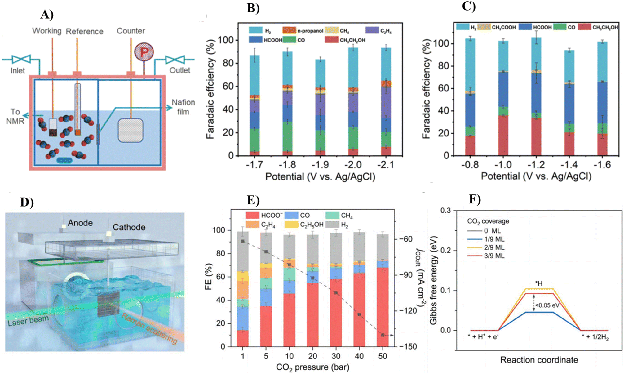 | ||
| Fig. 21 (A) Schematic of an electrolyzer cell with a high-pressure environment, (B) % FE of different products on the hollow sphere-Cu (HS-Cu) electrode under 1 bar and different potential conditions, (C) % FE of different products on the HS-Cu electrode under 100 bar and different potential conditions, (D) schematic of the customized high-pressure H-cell used for evaluating the CO2 reduction performance and conducting operando Raman spectroscopy, (E) % FE towards ECR of CO2 products and H2, as well as the partial current densities of ECR of CO2 on the Cu catalyst studied at various pressures at a potential of −1.1 V vs. RHE and (F) free energy diagram of HER on Cu(111) surface at different CO2 coverages.14,51 | ||
Corson et al. studied the effect of pressure and temperature at multiple applied potentials under both dark and illuminated conditions to understand the mechanism of selectivity changes driven by plasmon-enhanced electrochemical conversion. In their study, the pressure of CO2 was varied from 0.2 to 1 atm during the analysis by linear sweep voltammetry and chronoamperometry at −0.7, −0.9, and −1.1 V vs. RHE. They reported that at a given applied overpotential, the total current density increased with an increase in the pressure in both the dark and under light. However, there was a significant difference in the Tafel behavior between the dark and illuminated conditions. The reduction of CO2 to CO was found to show first-order behavior with respect to the pressure of CO2 at all the specified applied potentials in both the dark and under light. This likely indicates that no change was shown in the rate-determining step upon illumination.213
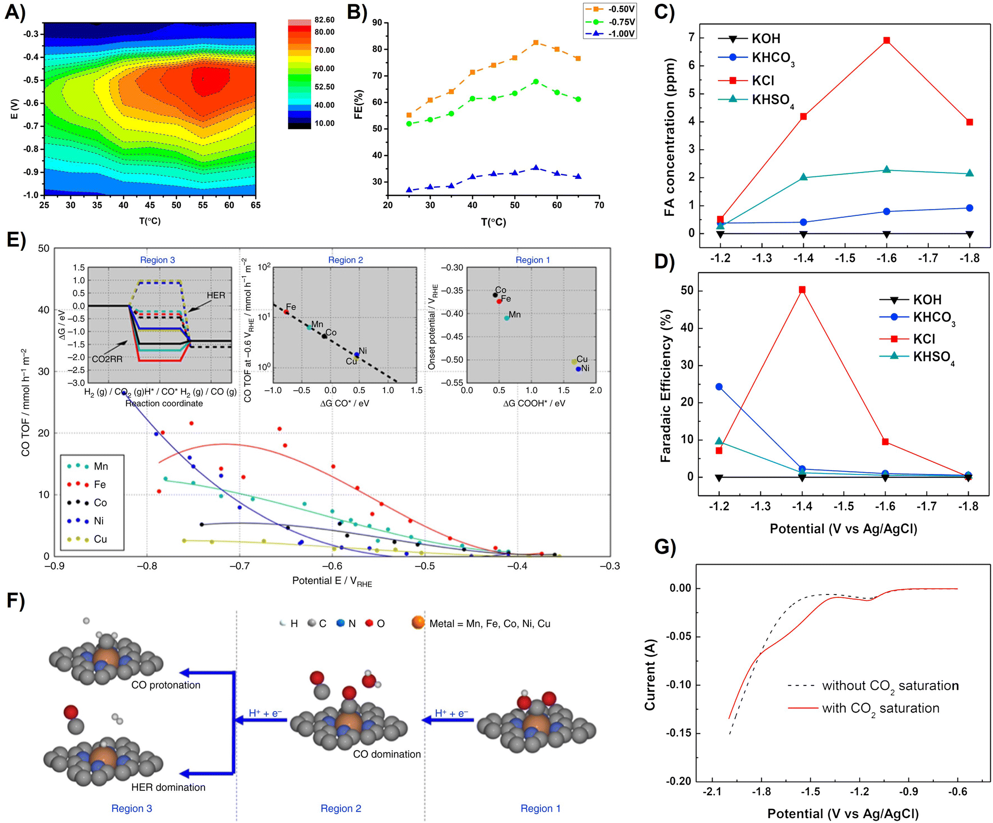 | ||
| Fig. 22 (A) % FE for CO formation plotted as a function of both potential and (B) temperature and as a function of temperature. (C) Amount of formic acid produced and (D) % FE at different reduction potentials according to the type of catholyte with a fixed concentration of 0.5 M; KOH, KHCO3, KCl, and KHSO4. (E) Catalytic reactivity trends and (F) reaction pathway split into 3 potential regions with distinctly different rate-determining mechanistic features. (G) LSV result for CO2 reduction; 0.5 M KCl (catholyte) and 0.1 M KOH (anolyte); CO2-free KCl (black dashed line) and CO2-saturated KCl (red straight line). Region 1: low over potentials, region 2: intermediate over-potentials, CO production TOF at −0.6 V RHE correlates with the free energy of adsorbed CO, region 3: high over potentials.55,198 Fig. 22C, D and G, reproduced with permission. ©2014, Elsevier. | ||
The reduction potential or standard electrode potential for the formation of each product in ECR of CO2 is different. The sluggish kinetics of ECR of CO2 means that a much more negative potential is needed to drive the reactions at a favorable rate than implied by the standard electrode potential value. This is because the activation energy of the CO2 molecule to create the CO2˙− radical anion, which is considered the first elementary electron transfer step in the reduction process, is only achieved at a very negative applied potential (−1.9 V vs. RHE) on a non-catalytic surface. Regarding the development of electrocatalysts for ECR of CO2, it is important to lower the kinetic energy barriers and improve the energy efficiency, which depend on the type of catalyst and techniques for its modification.214Table 3 presents a comparison of the overpotential on each catalyst together with the maximum FE%, product type, reactor type and electrolyte solution.
| Product | Catalyst | Potential (V vs. RHE) | Electrolyte | FE% (∼) | Reactor type | Ref. |
|---|---|---|---|---|---|---|
| HCOOH | Cu NP | −0.91 | 0.5 M KHCO3 | 15 | H-cell | 3 |
| Cu3Au NP | −0.91 | 0.5 M KHCO3 | 11 | H-cell | ||
| S-doped Cu2O derived Cu | −0.80 | 0.1 M KHCO3 | 74 | H-cell | 215 | |
| S-modified Cu | −0.80 | 0.1 M KHCO3 | 80 | H-cell | 216 | |
| Cu2O/CuO/CuS | −0.70 | 01. M KHCO3 | 84 | H-cell | 217 | |
| Nano-Sn/graphene | −1.80 | 0.1 M NaHCO3 | 94 | H-cell | 218 | |
| Pd NP/C | −0.15 | 2.8 M KHCO3 | 95 | H-cell | 219 | |
| Mesoporous SnO2 | −0.90 | 0.5 M NaHCO3 | 83 | H-cell | 220 | |
| Sn–OH | −1.15 | 0.1 M KCl | 82 | H-cell | 221 | |
| CuSn3 alloy | −0.50 | 0.1 M KHCO3 | 95 | H-cell | 222 | |
| SnO2 NPs | −0.95 | 1 M KOH | 46 | Flow cell | 223 | |
| Cu-doped Bi NPs | −1.20 | 0.5 M KHCO3 | 90 | H-cell | 224 | |
| Bi NPs | −0.83 | 0.5 M KHCO3 | 94 | H-cell | 225 | |
| Bi nanosheets | −0.90 | 0.5 M NaHCO3 | 95 | H-cell | 226 | |
| B-doped Pd | −0.50 | 0.1 M KHCO3 | 70 | H-cell | 227 | |
| Electrodeposited Pd film | −0.40 | 0.1 M KHCO3 | 55 | H-cell | 228 | |
| PbO2-derived Pb | −0.80 | 0.5 M NaHCO3 | 100 | H-cell | 229 | |
| CO | AuCu NP | −0.91 | 0.5 M KHCO3 | 82 | H-cell | 3 |
| AuCu3 NP | −0.91 | 0.5 M KHCO3 | 47 | H-cell | ||
| Cu–Ag NP | −1.1 | 0.5 M KHCO3 | 65 | Flow cell | 122 | |
| Au NP | −0.91 | 0.5 M KHCO3 | 77 | H-cell | 3 | |
| Cu NP | −0.91 | 0.5 M KHCO3 | 38 | H-cell | ||
| Ag/PTFE | −0.70 | 1 M KOH | 90 | GDL-flow cell | 230 | |
| Ag dendrites on Cu foam | −0.80 | 0.5 M KHCO3 | 96 | Flow cell | 231 | |
| Ag-CNT | −0.80 | 1 M KOH | 100 | GDL-flow cell | 232 | |
| AuCu alloy NPs | −0.38 | 0.5 M KHCO3 | 90 | H cell | 233 | |
| Mesoporous Ag | −0.60 | 0.1 M KHCO3 | 90 | H cell | 234 | |
| CuSn | −0.60 | 0.1 M KHCO3 | 90 | H cell | 235 | |
| C2H5OH | Dual single atom Ni/Cu | −0.4 | 0.5 M KHCO3 | 36 | H-cell | 236 |
| Dual single atom Ni/Cu | −0.60 | 0.5 M KHCO3 | 92 | H-cell | ||
| Dual single atom Ni/Cu | −0.80 | 0.5 M KHCO3 | 84 | H-cell | ||
| CuO NS | −0.8 | 0.1 M KHCO3 | 30 | H-cell | 237 | |
| CuO NS | −1.0 | 0.1 M KHCO3 | 27 | H-cell | ||
| CuO NS | −1.1 | 0.1 M KHCO3 | 21 | H-cell | ||
| Dual single atom Ni/Cu | −1.0 | 0.5 M KHCO3 | 58 | H-cell | 236 | |
| Cu–Ag NP | −1.1 | 0.5 M KHCO3 | 17 | Flow cell | 122 | |
| Dual single atom Ni/Cu | −1.2 | 0.5 M KHCO3 | 45 | H-cell | 236 | |
| Defect-rich Cu surface | −0.95 | 0.1 M KHCO3 | 53 | H-cell | 238 | |
| C2H4 | Defect-rich Cu surface | −1.23 | 0.1 M KHCO3 | 60 | H-cell | |
| Cu–Ag NP | −1.1 | 0.5 M KHCO3 | 14 | Flow cell | 122 | |
| CH4 | Cu–Ag NP | −1.1 | 0.5 M KHCO3 | 6 | Flow cell | |
| C3H7OH | Defect-rich Cu surface | −1.08 | 0.1 M KHCO3 | 18 | H-cell | 238 |
| CH3COCH3 | Dual single atom Ni/Cu | −0.4 | 0.1 M KHCO3 | 10 | H-cell | 236 |
Kim et al. studied the % FE towards the formation of CO at average overpotentials, observing the highest value at a temperature of 55 °C, as shown in Fig. 25B. At higher overpotentials, the optimum temperature remained 55 °C; however, the differences in % FE between different temperatures became smaller. As shown in Fig. 25C, when KOH and KHCO3 were used as the catholytes, the amount of HCOOH was significantly low. The maximum amount of HCOOH obtained with KHSO4 was 2.2 ppm at −1.6 V. However, with KCl, the resulting amount of HCOOH increased with a reduction potential up to −1.6 V, reaching a maximum amount of ∼7 ppm. Any further increase in the potential decreased the amount of HCOOH.
Fig. 22G shows the LSV results with and without CO2 purging in the catholyte, where it can be observed that the current in the absence of CO2 increased rapidly at −1.5 V, indicating the generation H2. The current from the CO2-saturated catholyte was slightly higher than that from the CO2-free catholyte in the potential range of −1.1 to −1.8 V. The difference in the currents became considerable at potentials more negative than −1.4 V, implying that the excess current corresponded to the reduction of CO2. As the potential became more negative than −1.8 V, H2 production became dominant over CO2 reduction, resulting in an i–v behavior similar to that of the CO2-free catholyte. Therefore, the potential range varying from −1.2 to −1.8 V vs. Ag/AgCl was chosen for further investigation. Moreover, the selected potential range was in good agreement with the literature values. Fig. 22D indicates that the efficiencies of KOH, KHCO3, and KHSO4 were <10% over all the potential ranges, except for KHCO3 at −1.2 V (24%), owing to the low amount of HCOOH. In the case of the KCl catholyte, the efficiency was maximum (50.4%) at −1.4 V, although the amount of resulting HCOOH was the highest at −1.6 V. Ju et al. investigated the activity and selectivity of metal–nitrogen-doped carbon catalysts for the electrochemical reduction of CO2, which were found to be potential dependent for CO and hydrogen, as shown in Fig. 22E and F.55,202
H-type cells are widely applicable due to their simple assembly and operation. The product separation in this reactor type is effective. It has versatile configurations and low cost. An H-type cell usually consists of an intermediate ion exchange membrane and two symmetrical electrolytic cells chambers. The actual separation of the anode and cathode restricts the occurrence of side reactions together with the reduction of CO2. The reaction process needs the flow of CO2 gas into the cathode chamber. In the cathode section, CO2 is dissolved in the electrolyte, and then undergoes a reduction reaction with the cathode surface. The resulting gaseous product will pass into the gas chromatograph together with the CO2 gas, while the liquid reduction product will be retained in the electrolyte, and the liquid will be removed for subsequent detection using liquid chromatography or NMR.51
The flow cell mainly consists of a cathode chamber, a porous hydrophobic gas diffusion layer, and an ion exchange membrane and anode chamber. Unlike the H-cell, CO2 will go into the porous hydrophobic gas diffusion electrode (GDE) and undergo a reduction reaction with the catalyst and electrolyte at the gas–liquid–solid three-phase interface.2 It is possible to reduce the path of CO2 diffusion to the catalyst surface from about 50 μm in the H-cell to about 50 nm, resulting in a higher mass transfer efficiency.240 Therefore, GDE can provide a higher CO2 concentration at the three-phase interface compared to the H-cell, and this controllable localized CO2 concentration provides environmental conditions for the selective reduction reaction.51,240
The MEA-cell is built on the development of the flow-cell, and its basic components are similar to the flow-cell, retaining high mass transfer efficiency. The difference between a flow cell and MEA is that the MEA cell flows the CO2 gas with humidity into the GDE, and then directly reacts with the catalyst in the cathode chamber, avoiding the problems caused by the use of electrolytes. The direct contact between the cathode GDE and anode GDE and the membrane effectively reduces the distance between the electrodes, and therefore has a smaller ohmic loss.241 The ion exchange membrane in the MEA reactor has a high ion transfer rate, which can maintain the balance of ions inside the reactor and improve the efficiency and stability of the reaction.51 In comparison to H-cells, flow-cell reactors enable the CO2 reduction reaction operating at much greater current densities by mitigating the mass-transport limitation aspect. Mostly, the lack of a standard testing methodology has led to the inaccurate determination of the products in ECR of CO2, and thus unfair performance comparisons may occur. Niu et al. identified different commonly overlooked aspects based on product measurements during CO2 electrolysis in flow cells, which could cause a considerable misestimating even up to a ratio of 45% in certain situations. Their systematic experiments suggest a modified flow-cell testing method that permits the establishment of benchmarks in which products of ECR of CO2 can be accurately assessed. This pioneer study offers a rigorous protocol towards the accurate measurement of both liquid and gaseous products using flow cells.242 Weekes et al. found that flow cell systems provide a testing platform for electrocatalytic materials, which are more relevant to commercialization compared to the batch type H-cell experiments. They overviewed how the effect of non-catalytic components [i.e. gas diffusion layers (GDL), polymer electrolyte membrane (PEM), and flow field] and feedstock characteristics (e.g., gas vs. liquid, flow rate, and electrolyte supply) in the entire CO2 reduction performance in flow cells can supersede the activity of the electrocatalyst tested independently in an H-cell. By reviewing a few studies that systematically tuned the non-catalytic features of electrochemical flow reactors, there are several promising strategies that can drive the performance metrics for CO2 reduction toward industrially relevant levels, in terms of catalyst stability, current density, selectivity and efficiency.243
In addition to catalyst-focused and reactor-focused developments of many typical CO2 reduction reaction parameters, such as pH, flow rates, and hydrophobicity, Wong et al.247 proposed that a deeper fundamental understanding of the CO2 reduction microenvironment is necessary for optimizing the reduction activity and selectivity. These considerations are unavoidable regardless of the type of reactor, even if researchers do not intentionally aim to modulate the microenvironment. Therefore, the local microenvironment of ECR of CO2 can be significantly impacted by factors (chemical, transport, or reactor environment) that alter the circumstances at the active sites, whether intentional or not. Several significant factors, including the following, work together to contribute to the high sensitivity of the reduction to the microenvironment:
(a) Poor solubility of CO2 in watery environments.
(b) The careful balancing act between the delivery of necessary proton donors for ECR of CO2 and the potent propensity of the competing HER to transform supplied protons to H2.
(c) The intricate harmonization of reaction pathways leading to various reduction products.
(d) Dynamic adjustments to local pH, ion concentrations, hydrophobicity, and active sites in the reaction to electrocatalyst rearrangement and carbonate formation.
The local microenvironment near the catalyst surface determines the selectivity, activity and stability of the reduction process. The cations and anions of the electrolyte salt play a crucial role in the microenvironment near the catalytic surface in aqueous CO2 reduction, where they affect the activity and selectivity. To further understand their impact on the generation of the product over Cu, many studies examined the impacts of alkali metal/bicarbonate (MHCO3−) electrolytes (Li+, Na+, K+, Rb+, and Cs+) on ECR of CO2. In contrast to H2, CO, and CH4, the partial current densities associated with the synthesis of HCOO−, C2H4, and C2H5OH showed an increase with regard to the atomic radius of the cation, following the order of Li+ < Na+ < K+ < Rb+ < Cs+.89,248
The microenvironment of catalytic center plays a vital role in adjusting the activity, selectivity and stability of ECR of CO2, which has received increasing attention in the past few years. However, controllable microenvironment construction and the effects of multi-microenvironment variations for enhancing the ECR of CO2 performance remain unclear. Generally, as discussed in section 2.1.1, 2.1.2 and 2.1.3, the local microenvironment has potential to tune the results of the electrochemical reduction of CO2. The types of anions present in the electrolyte, ionomers and hydrophobicity of the catalyst can be categorized under the microenvironment that affects the effectiveness of ECR of CO2. Other microenvironments can also affect the performance of the reduction. For example, the gas diffusion layer has an impact on the activity and selectivity.
Bilayer cation and anion conducting ionomer coatings were used by Kim et al.174 to thoroughly investigate and optimize the microenvironment to regulate the local pH and CO2/H2O ratio (via ionomer properties), respectively. Further improvements in the local ratio of CO2/H2O and pH were made when the customized microenvironment was combined with pulsed electrolysis. This resulted in selective C2+ generation, which increased by 250% (with 90% FE and just 4% H2) in comparison to static electrolysis over bare Cu. These findings highlight the importance of modifying the catalyst microenvironment to enhance the overall performance of electrochemical synthesis. They showed that advantageous microenvironments for the selective synthesis of C2+ on Cu can be produced by using ionomer layers. They combined systematic studies of CO2 reduction on Cu covered by various ionomer layers with an analysis of the structure–property correlations of these ionomer films to completely clarify the impacts of the ionomers on the local Cu catalyst microenvironment. This enhanced comprehension was used to further improve the reduction activity and C2+ selectivity together with prior knowledge of pulsed electrolysis. The local concentrations of CO2, H2O, OH− and H+ can also be altered by ion-conducting polymers (ionomers) due to the hydrophobicity induced by their –CH2- or –CF2-containing backbone chains and the modulation of ion transport by the charged moieties at the ends of their side chains. However, little is known about how ionomers affect CO2 reduction; the majority of research thus far has been empirical and has provided various justifications for the effects of ionomer films on the ECR of CO2. Consequently, it is critical to establish a systematic understanding of how the ionomer layers affect CO2 reduction through changes in properties such as background charge, counter-ions, and ion exchange capacity. With this information, the chemical microenvironment around a Cu catalyst can be tailored for the best possible C2+ product formation.249,250
Dolmanan et al.251 found that tuning the local microenvironment induces switching between electrochemical CO2 reduction pathways in terms of the gas diffusion layer (GDL). They revealed that tuning the GDL pore size can be used to control the local microenvironment of the catalyst, resulting in significant changes in catalytic selectivity and efficiency. Their concept was shown by sputtering Ag films on hydrophobic PTFE substrates with six different pore sizes. They found that smaller pore sizes favor the formation of formate up to 43% FE. This is due to the influence of the pore size on the CO2 mass transport, which changes the local pH at the electrode, resulting in reaction pathway switching between CO and formate. Their results indicate the importance of the local microenvironment and its impact on ECR of CO2. Liu et al.252 performed a systematic investigation by tailoring the microenvironment in the catalyst layer of the GDE, showing that both solid PTFE and flexible Nafion nanoparticles are important to create robust and abundant triple-phase boundaries (TPB) with more active sites. In this scenario, CO2 and H2O meet at the nanosheet surface to output a high formate partial current density, i.e. 380 mA cm−2 with an FE of 88.4%. Furthermore, these new Nafion/PTFE/SnO2 TPB porous structures largely increased the single-pass carbon efficiency up to 29.3% in aqueous electrolyte. This study depicts that engineering the TPB active sites is an efficient approach for the design of advanced CO2 electrolyzers. Wang et al.253 highlighted the representative strategies for tuning the catalyst and local microenvironments to increase the selectivity and activity of ECR of CO2. This group addressed the multifactor synergistic effects of microenvironment regulation for improving the CO2 accessibility, stabilizing the key intermediates, and enhancing the activity of ECR of CO2.
Tuning and controlling the microenvironments in ECR of CO2 will be beneficial for promoting, and eventually achieving the industrialization of the conversion of CO2 through electrochemical techniques. Promoting and ultimately attaining the industrialization of CO2 conversion via electrochemical technology will benefit from the tuning and management of the microenvironment in the ECR of CO2. To further develop the reduction process, new methods for comprehending and controlling the microenvironment must be developed. In the upcoming years, there will be fascinating new breakthroughs in this microenvironment frontier.
2.2 Intrinsic factors of ECR of CO2
In addition to the extrinsic conditions, intrinsic factors also have a major impact on the activity performance and product distribution of ECR of CO2. These factors include the active sites of the electrocatalyst, particle size, electrochemical surface area (ECSA), binding strength of the catalyst surface with CO2 and the reduction intermediates, surface structure of the electrocatalyst, electric field, impact of strain, dangling bonds and electric field. The impacts of each factor are discussed in the following sub-sections.| Catalytic activity = site activity × number of active sites | (2) |
Mostly, techniques for the in situ characterization of ECR of CO2 under real operating conditions provide an intense understanding of the reaction mechanisms, material structures, and surface sites. Raman spectroscopy, X-ray absorption spectroscopy, X-ray photoelectron spectroscopy, X-ray absorption spectroscopy, scanning electron microscopy, and transmission electron microscopy are the common techniques employed to identify the active sites of electrocatalysts through analyzing various features and properties of the electrocatalyst material.54,264
The active sites for ECR of CO2 to single-carbon or multi-carbon (C2+) products over metal electrocatalysts have been under long-term intense debate. To improve the activity and selectivity of the catalyst for C2+ products, it is crucial to understand the nature of its active sites applicable for the reduction of CO2. Cheng et al. investigated the atomic structure design for product-specific active sites on oxide-derived copper catalysts in ECR of CO2. This group described actual oxide-derived copper surface models by simulating the oxide-derived process through molecular dynamic demonstration with neural network potential. Following the examination of more than 150 surface sites via neural network potential-based high-throughput testing, coupled with DFT analysis, three square-like sites for C–C coupling were highlighted. Among them, convex-square sites and the sum of grain boundaries such as planar-square sites are accountable for the formation of ethylene. Meanwhile, the step-square sites, i.e. n(111) × (100), favor the production of alcohol. This is because of their geometrical position for stabilizing the acetaldehyde intermediates and destabilizing the Cu–O interactions, which were quantitatively described by experimental and theoretical studies. These research findings provide crucial insights into the origin of the activity and selectivity on Cu-based catalysts, demonstrating the value of their research framework in identifying the active sites in complex heterogeneous catalysts.37,265,266
Cheng et al. also presented the pathway for C2+ products,37,38,267,268 as shown in Fig. 23A. This group randomly selected 155 surface sites on oxide-derived copper surface models to elaborate this dimerization process (Fig. 23B). According to the reaction energy of the C–C coupling process, as seen in Fig. 23C, the average reaction energy on the square sites is 1.27 eV, which is 0.36 eV lower than that of the non-square sites. For this reason, square-like sites are the most potential favorite to serve as the active sites for C–C coupling. For the purpose of inspecting C–C coupling more precisely, they abstracted four different surface sites (step-square, planar-square, concave-square, and convex-square) into small slab models for accurate density functional theory calculations (Fig. 23D). These four active sites are expected to have similar chemical properties to the selective sites. The DFT results indicate that the CO dimerization reaction based on these four square-like structures is less endothermic than that of the Cu(111) and Cu(221) facets under the optimal electrochemical interface (Fig. 23E and F).37,166
 | ||
| Fig. 23 Identification of C–C coupling active sites: (A) reaction pathway for C2+ products in CO2 reduction; (B) adsorption energy of *COCO as a function of the average adsorption energy of two adsorbed *CO; (C) reaction energy (2*CO → *COCO) as a function of the average E(*CO) on these sites; D) DFT periodic slab models of four square-like sites; E) *OCCO configurations on these four sites (solvent molecules have been removed to show the adsorbate configurations); F) reaction energies, and G) barriers (2*CO → *COCO) on different DFT slab models under appropriate electrochemical interface. Color code: brown-Cu; yellow-Cu in square-like sites; gray-C; and red-O.37 | ||
Cheng et al. formulated a theoretical simulation for the ECR of CO2 over oxide-derived copper catalysts (Fig. 24). As shown in the theoretical simulation, Fig. 24A shows that oxygen below the third layer had a very small effect on the adsorption behavior of the adsorbates.37 Therefore, this group reported that their oxide-derived copper surface models are consistent with the current experimental research in which metallic copper is the active phase for ECR of CO2 over the oxide Cu rather than the oxide phase.269 In their simulated OD-Cu surface structures, as shown in Fig. 24B, the (111) facet is dominant, occupying about 53% of the surface area. In addition, there are a few clear steps, which resemble the Cu(S)–[n(111) × (111)] step sites in which one atomic height of the (111) step is introduced into several atomic rows of the (111) terrace. Furthermore, some defects such as grain boundaries and vacancies exist, as revealed in the simulation. To date, authentic oxide-derived copper surface structures are obtained based on molecular dynamic simulation with global neural network potential simulation of the whole reduction process.37,107,265,270
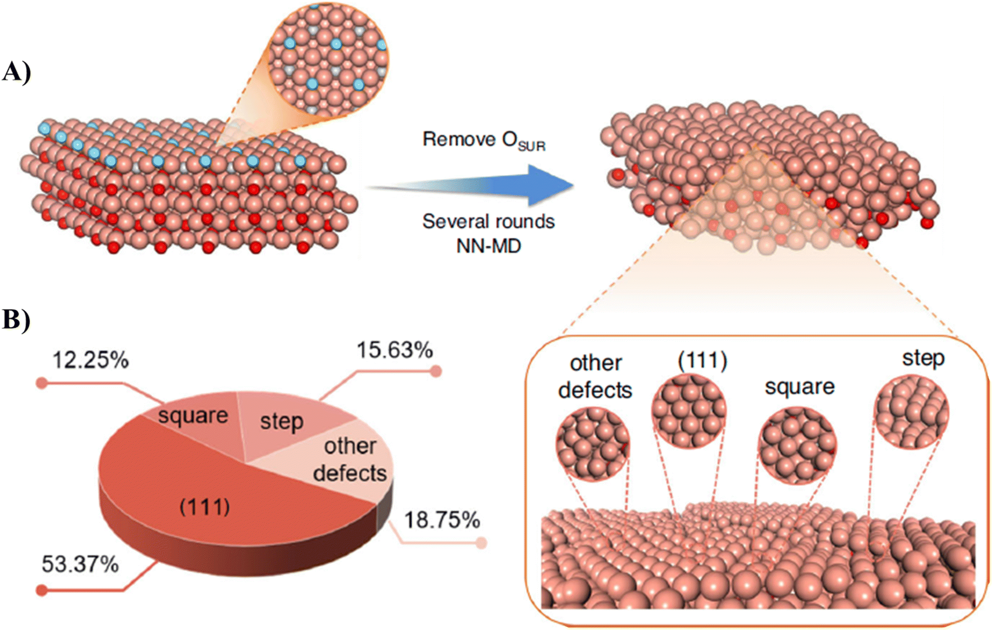 | ||
| Fig. 24 Theoretical simulation of oxide-derived process. (A) Illustration of our procedure to construct OD-Cu model with molecular dynamic simulation. Color code: brown-Cu; blue-surface O; gray-subsurface O; red-bulk O. (B) Proportions of different surface structures.37 | ||
Hursán et al. studied an advanced and interesting way to prepare a series of M–N–C catalysts (M = Fe, Sn, Cu, Co, Ni, and Zn), which was investigated using operando X-ray absorption spectroscopy. They observed that Sn–N–C and Fe–N–C are prone to oxide cluster formation even before ECR of CO2. Alternatively, the respective metal cations are singly dispersed in the as-prepared Cu–N–C, Co–N–C, Ni–N–C, and (Zn)–N–C. During CO2RR, metallic clusters/nanoparticles were reversibly formed in all the catalysts, except for Ni–N–C. Their result shows that the competition between M–N and M–O interactions is a crucial factor determining the mobility of the metal atom in M–N–C. Specifically, the strong interaction between the Ni centers and the N-functional groups of the carbon support results in good stability of the Ni single-sites. This leads to an outstanding performance by Ni–N–C in ECR of CO2 towards the formation of CO (above 90% FE) compared with other transition metals used in these types of coordinated catalysts. They characterized this coordinated material using high-resolution STEM (HR-STEM) before and after the reduction of CO2. According to the interesting images (Fig. 25), it is possible to identify not only the amorphous carbon structure of the materials but also the availability of single metallic atoms in the carbon matrix. These single atoms are most apparent in the case of Sn–N–C because Sn has the highest atomic number among the studied metals, and thus the contrast between C and Sn is the highest. In the case of Fe–NCcryst, single-atoms are also available (Zn or Fe), in addition to the observed iron oxide nanoparticles. The high-resolution HR-STEM images (bottom) revealed the disordered structure of the carbon framework and overview of the single atom doping of the added metals (yellow circles) as well as availability of small clusters and nanoparticles.271
 | ||
| Fig. 25 (A) High-angle annular dark-field scanning transmission electron microscopy (HAADF-STEM) images of the metal–nitrogen-doped carbon (M–NC) catalysts in the as-prepared state and (B) after performing ECR of CO2 at −1.15 V for 80 min. Low-magnification (top) images show the morphological features of the M–N–C nanostructures and the presence of nanoparticles/aggregates (marked with red arrows). Reproduced with permission.271 ©John Wiley and Sons. | ||
A large number of active sites and high site activity (turnover frequency, TOF) enable the ECR activity of CO2 to be improved. The common techniques to increase the number of active sites and surface area are (a) fabrication of efficient electrocatalysts with different morphologies to enhance the active edge sites such as nanoparticles, nanowires, defect-rich films, porous nanosheets, mesoporous films, core–shell structure of bimetallic, nanoflakes and nanoflower properties of the electrocatalyst; (b) chemical doping for the increment of the activity of edge sites; and (c) activating the basal plane by introducing new vacancies, strain, and/or grain boundaries. Basically, to improve the TOF, overpotential, and tgaqciecan be calculated from the polarizatnsity of the ECR of CO2, different structural engineering and surface modification of the electrocatalyst can be performed. To understand the efficient ECR of CO2, the TOF and Tafel slope values are the common parameters that need to be quantified.259
TOF of a specific electrocatalyst can be calculated using eqn (3).
 | (3) |
Tafel analysis, derived from Butler–Volmer kinetics, is a powerful and common tool that has long been used to assist in the understanding of electrochemical mechanisms. By determining the logarithm of current against applied potential, information can be obtained regarding the number of protons and electrons transferred before the rate-determining step (RDS). Through better mechanistic understanding, catalysts and systems can be adjusted and optimized to minimize the energy barriers and change the selectivity. However, recently, it has emerged that this method provides only limited reliable insight, in part because of the overreliance on the Tafel slope and bias toward reporting cardinal values. The effects from mass transport can hide the observation of the desired Tafel behavior. CO, an intermediate in the path to carbon-coupled products of ECR of CO2, has been used as the reactant to try and simplify mechanistic studies. However, this type of technique cannot replicate the catalyst microenvironment resulting from HCO3/CO2 equilibrium, pH gradients, and equilibration of the electrode with CO as a product, highlighting the importance of directly interrogating CO2 reduction systems. The Butler–Volmer equation (eqn (4)) is used to calculate the Tafel plot.
 | (4) |
The Tafel plot is derived from the Butler–Volmer equation, which calculated as shown in eqn (5).
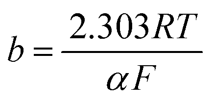 | (5) |
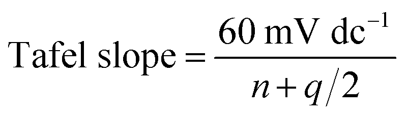 | (6) |
Watkins et al. observed that an increase in the hydrodynamics at the surface of the electrode directly alters the methane and ethylene Tafel slopes, indicating that mass transport is on equal footing with the catalyst active sites in analyzing the reaction mechanisms and the ensuing product distribution.273 Generally, it is believed that ECR of CO2 towards CO proceeds through *COOH and *CO intermediates, but the rate-limiting step remains a key point of controversy. According to recent Tafel analysis and kinetic isotope effect (KIE) studies, three different reaction steps have been hypothesized to be rate limiting, as follows: (a) electron transfer to CO2 and concomitant adsorption, (b) proton transfer to *CO2 to form *COOH or *COOH to form a protonated *COOH complex, and (c) electron transfer to *COOH to form *CO.274–277 In the outstanding experimental work by Ringe et al., they elucidated the long-standing controversy surrounding the rate-limiting step of ECR of CO2. They carried out the experiment on gold at neutral to acidic pH values. They found that the CO formation rate is constant with pH on a standard hydrogen electrode scale. Based on this phenomenon, they concluded that the CO production rate is limited by the CO2 adsorption step. This research group established a new multi-scale modeling platform that integrates the beginning of the reaction kinetics with mass transport simulations, explicitly considering the charged electric double layer. The model reproduced the experimental CO polarization curve and showed the rate-limiting step to be *COOH to *CO at low overpotentials, while CO2 mass transport and CO2 adsorption at intermediate overpotentials at high overpotentials. Finally, their research output revealed that the Tafel slope increases from the electrostatic interaction between the interfacial field and the dipole of *CO2. This experimental research indicates the importance of surface charging for mass transport and electrochemical kinetics. They also discussed the reasons for the controversy and provided experimental and theoretical evidence for field-driven CO2 adsorption as the limiting step of ECR of CO2.195
Hossain et al. investigated the reaction mechanism and kinetics for ECR of CO2 on Ni single-atom catalysts based on quantum mechanics. Their experiments indicated that graphene-supported Ni-single atom catalysts (Ni-SACs) provide a promising platform for the ECR of CO2 towards CO. Given that the nature of the Ni sites (Ni–N2C2, Ni–N3C1, Ni–N4) in Ni-SACs has not been determined experimentally, they were interested in developing grand canonical potential kinetics (GCP-K) formulation of quantum mechanics to predict the kinetics as a function of applied potential to determine the TOF, Tafel slope and FE% for CO and H2 production for all three sites. According to their report, they examined the kinetics and reaction mechanism for ECR of CO2 over graphene-supported Ni-SACs using the new GCP-K formulation. This allowed the geometry of the transition states and the charge transfer from the electrode to adsorbed species to alter continuously along the reaction coordinates as the potential varied. GCP-K showed the electron transfer accompanying proton transfer as a continuous process instead of a discrete electron jump as in the proton coupled electron transfer (PCET) formulation of the traditional Butler–Volmer kinetics.278
The CO-strip technique is based on the electrochemical oxidation of an adsorbed layer of CO from a sample surface of interest. Usually, it is analyzed using voltammetry combined with a mass spectrometer. This method can be considered an EC-MS application. This technique is often used to quantify the active surface area of a sample and can deliver insight into the crystalline facets and binding energies of the adsorbed species. Additionally, the CO2 mass spectrometer (MS) signal of the EC-MS may be calibrated via the CO-strip technique. Eqn (7) is used for the analysis of CO-stripping.
| *CO + H2O → CO2 + 2H+ + 2e− | (7) |
Xu et al. synthesized carbon-supported Sn electrocatalysts with the tin size varying from single atom, ultrasmall clusters to nanocrystallites for selective ECR of CO2. This single-atom electrocatalyst resulted in high single-product FE% and low onset potential of CO2 conversion to acetate with FE of 90% at −0.6 V, 92% ethanol at −0.4 V, and 91% formate at −0.6 V. The ECR of CO2 on these highly selective, size-modulated p-block element electrocatalysts was studied by computational modeling and structural characterization together with kinetic isotope effect investigation.284 Metal–organic frameworks (MOFs) are also considered better platforms for investigating catalytic mechanisms due to their well-defined active sites and tunable coordination structures. These types of platforms can attain high FE and selectivity towards specific products.285 Hwang et al. reported that NiCu-SACs/N–C electrocatalysts with cooperative dual hetero-active sites can attain the highest FE% (92.2%) at −0.6 V vs. RHE towards the formation of ethanol (Fig. 7).236 Their result shows that the single-atom electrocatalyst system exhibits the lowest onset potential i.e. at −0.4 V versus RHE to reduce CO2 towards ethanol. The dual single-atom catalyst exhibited an outstanding performance in terms of current density generation, FE% of each product and TOF of ethanol, as shown in Fig. 26A–F.236
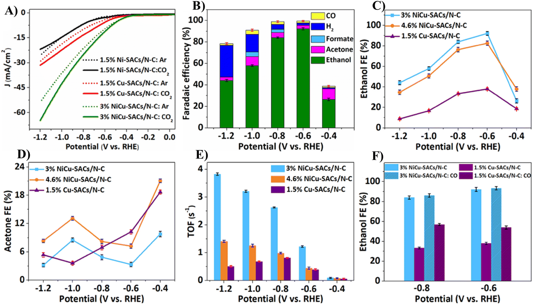 | ||
| Fig. 26 (A) LSV curves of 3% NiCu-SACs/N in 0.5 M KHCO3. (B) FE% & product distribution on 3% NiCu-SACs/N–C. (C) FE% of ethanol, (D) FE% of acetone, and (E) TOF of ethanol over NiCu-SACs/N–C hybrids with different metal loadings at different applied potentials. (F) FE% of ethanol over 3% NiCu-SACs/N–C and 1.5% Cu-SACs/N–C. Reproduced with permission.236 ©2024, Elsevier B.V. | ||
This result indicates that single-atom electrocatalysts are efficient for the electrocatalytic conversion of CO2 due to their maximum atomic utilization of Cu and Ni single atoms.
In another case, the unsaturated metal sites of the coordination network materials act as Lewis acid sites, which are considered active electrocatalysts. A few studies reported that the exposed metal atoms in coordination networks were used as active sites of single-atom electrocatalysts for CO2 reduction. Jin-Hang et al. studied the catalytic features of transition metal–tetracyanoquinodimethane (TM–TCNQ) monolayers as single-atom catalysts for ECR of CO2. Their results revealed that the TM–TCNQ monolayers are highly efficient and stable to bind the isolated metal atoms in the specified site of the monolayer. The coordinated atom in TM–TCNQ acts a single-atom electrocatalyst for efficient utilization in the catalysis process.286 Herein, selected single-atom active sites with their support, FE% for products and electrolyte used are compiled in Table 4.
| SACs | Support | Electrolyte | Product | FE% | Ref. |
|---|---|---|---|---|---|
| Fe–N–C | N-doped porous carbon | 0.1 M KHCO3 | CO/CH4 | 70%/0.09% | 287 |
| Ni–N–C | N-doped porous carbon | 0.1 M KHCO3 | CO | 85% | |
| N–C | N-doped graphitic | 0.1 M KHCO3 | CO | 20% | 288 |
| Co–N–C | N-doped graphitic | 0.1 M KHCO3 | CO | 45% | |
| Fe–N–C | N-doped graphitic | 0.1 M KHCO3 | CO | 93% | |
| Cu–C3N4 | Graphitic carbon nitride (g-C3N4) | 0.1 M KHCO3 | CO/CH4, CH2H4, C2H6, CH3CH2OH | 40%/<10% | 289 |
| In SACs-800 | MOF-derived NxC4−x (1 ≤ x ≤ 4) | 0.5 M KHCO3 | CO/HCOOH | 38%/52% | 290 |
| In SACs-1000 | NxC4−x (1 ≤ x ≤ 4) | 0.5 M KHCO3 | CO | 97% | |
| M–N–C | N-doped carbon materials | 0.1 M KHCO3 | CO | 80% | 291 |
| Ni/Cu cooperative dual single atom | N–C coordinated | 0.5 M KHCO3 | C2H5OH | 92% | 236 |
| Ni/Cu cooperative dual single atom | N–C coordinated | 0.5 M KHCO3 | Acetone | 12% |
Alternatively, Mistry et al.292,296 obtained their ECSAs from double-layer capacitance measurements, which are known to produce inaccurate findings due to the notable variations in particular double-layer capacitances among porous catalysts. This can be aggravated by choosing potential windows and/or scan rates erroneously. As an alternative, additional research has used metal underpotential deposition (UPD) techniques to estimate the ECSA of Au electrocatalysts. These techniques are based on the potential-controlled adsorption of a Pb or Cu (sub)monolayer on the Au surface, and they are likely the most dependable methods for this purpose.297,298
Chauhan et al.292 used surface oxide reduction and copper underpotential deposition techniques to measure the ECSA of an Au aerogel with a web thickness of about 5 nm. Subsequently, the ability of the aerogel to reduce CO2 was evaluated in a two-compartment electrochemical cell that was created internally. Similar measurements were also performed on polycrystalline Au and a commercial catalyst made of Au nanoparticles supported on carbon black (Au/C) for comparison. Compared to Au/C, the Au aerogel showed an FE of 97% for CO synthesis at ≈−0.48 V RHE, with the suppression of H2 production, which is attributed to the larger Au-particle size. At the potential of maximum CO generation, the aerogel network, in contrast to Au/C, maintained its nanoarchitecture, according to identical location transmission electron microscopy of both nanomaterials before and after CO2 reduction. Potential-hold Cu-UPD measurements yield a far more accurate ECSA quantification than the frequently used potential-sweep Cu-UPD method, and the results showed the ECSAs of polycrystalline Au, Au on carbon, and unsupported Au aerogels using the surface oxide-reduction and Cu-UPD methods.
Generally, it is believed that the catalysts used for electrocatalytic CO2 reduction will have the highest possible activity, stability, and product selectivity. The electrochemically active surface area (ECSA) of electrocatalysts is one of the crucial intrinsic factors that affect their CO2 ECR outputs. ECSA typically relies on the morphology, structure, atom arrangement, and texture of the catalyst surface, which contains the active sites for electro-catalytic activity. The number of active sites and site activity on a particular catalyst refer to its activity as an electrocatalyst. Assuming that the catalyst surface is porous or hollow, a high ECSA should result in high catalytic activity throughout the reduction process. The ECSA of the catalyst can be determined using eqn (8).4,299,300
| ECSA = Rf × S | (8) |
Using an anionic electrolyte membrane electrode assembly, Uenishi et al. investigated the effect of the catalyst surface area, as evaluated by electrochemical techniques, on the performance of CO2 electrolysis cells. Cyclic voltammetry and copper under-potential deposition were used to examine the ECSA of the active metals supported on the carbon of the cathode side catalyst layer. The ECSA determined using stripping cyclic voltammetry in the copper under-potential deposition process is shown in Fig. 27A. The smaller the particle size, the higher the ECSA in the comparison of 2 and 4 nm nanoparticle gold-loaded carbon; nevertheless, the 12 nm nanoparticle gold-loaded carbon had the highest ECSA. According to their preliminary experimental prediction, the ECSA decreases as the particle size increases. This is true for 2 nm and 4 nm particles. However, the ECSA increased as the particle size reached 12 nm.50,248 Using the Cu under-potential deposition approach, the CV results are shown in Fig. 27B. The difference between cyclic voltammetry stripping and cyclic voltammetry following copper under-potential deposition varied with grain size.
 | ||
| Fig. 27 (A) Effect of nanoparticle diameter on ECSA calculated with copper under-potential deposition stripping voltammetry. (B) Copper underpotential deposition stripping voltammetry on each nanoparticle diameter (D = 2, 4, and 12 nm). Electrolyte concentration: 0.5 M H2SO4 and 50 mM copper(II) sulfate (CuSO4)·5H2O. The scan direction: forward scan.50 | ||
The findings obtained by Uenishi et al. provide guidelines for improving the catalytic performance of CO2 electrolysis cells using an anionic electrolyte membrane electrode assembly (MEA), and these results will promote efforts toward achieving carbon neutrality. They concluded that although the ECSA tends to increase with a decrease in particle size, the effective ECSA does not always correlate with particle size because gold may not be supported on the effective area for the electrochemical reaction when the particle size is too small. In addition, the electrolytic current density and FE of the target product are not necessarily correlated with the effective ECSA, suggesting the need to optimize the design of the electrolyte membrane, which determines the balance among the amount of CO2, pH of the atmosphere, and active metal loading.50
Zhen et al. studied the detailed optimization on a large scale to get serious realistic nanoparticle (NP) models of various particle sizes and the identification of atomic-level structures of active sites for CO products on CuZn and CuAu NP catalysts in ECR of CO2 using DFT calculations and machine learning. After the analysis of 300 surface sites (600 computational data points) through neural network (NN) potential-based high-throughput testing, they showed that the bimetallic Cu-based NPs have superior activity for the catalytic reduction of CO2. This is because many bimetallic synergistic effect sites significantly stabilize the carboxyl intermediate during CO2 reduction to CO, breaking the inherent linear relationship. Their work shed light on the structure-performance relationship over more realistic large NPs, facilitating the rational design of Cu-based catalysts in the ECR of CO2.
| ε = (dp − ds)/ds | (9) |
 | ||
| Fig. 28 Schematic of formation mechanisms and types of strains.303 | ||
Electrocatalysts with 2D nanosheets have attracted interest due to their unique structural and electronic features; however, this research area is still in its infancy. Ultrathin nanosheets containing open double-sided surfaces possess abundant exposed surface atoms, which can easily escape from the respective lattice to create vacancy-type defects. These defects together with the structural disorder that usually exists in nanosheets tend to reduce the coordination number of the surface atoms. This scenario leads to the formation of dangling bonds, increasing the catalytic activities in ECR of CO2. An increase in low-coordinated surface sites promotes the chemisorption of the reactants. Controlling the vacancy defects allows a change in the electronic structure and the corresponding catalytic activities in the reduction process. The properties of nanosheets can be easily controlled by altering their thickness and exposure to external stimuli/inducement such as strain, illumination, and electric field, directing new insights to engineer 2D materials for the electrocatalysis and photocatalysis of CO2. The intensity of these external stimuli will have an influence on the properties of 2D materials, significantly affecting the selectivity and activity of the electrocatalyst in the CO2 reduction process. Sun et al. reviewed the fundamentals and challenges of ECR of CO2 specifically on 2D materials.7
A dangling bond refers to an unsatisfied valence on an immobilized atom, mostly found in solids with unpaired electrons. It is an immobilized free radical that can react with other ions or molecules by sharing an electron pair. Dangling bonds play a key role in the growth of crystals and can lead to the anisotropic growth of nanoparticles. This results in unique optical performances and catalytic functionalities. Although single-atom catalysts (SACs) have attracted enormous attention for application in the ECR of CO2 due to their extraordinary catalytic performance and well-defined active sites, the neighboring impacts and their influence on the catalytic performance of SACs have not been well investigated. Wong et al. presented a review on the neighboring effects on SACs for the ECR of CO2. They reported that the surrounding atoms not only induce electronic modulation of the metal atom but also participate in the reduction process. In their analysis, both experimental and theoretical investigations depicted that the neighboring sites of the anchored metal center can contribute or provide second active locations in the catalysis process. This scenario enhances the performance of CO2 reduction. The edge defects and vacancies on graphitic layers during ECR of CO2 played a crucial role during intermediate formation. A comprehensive study into the reactivity and catalytic sites of M–N4 SACs (M = Fe and Co) for ECR of CO2 revealed that the nearby C atoms with dangling bonds played a vital role in dissociating *COOH for the formation of CO. It is convincing that the remarkable CO2 reduction preference of their synthesized M–N4 SACs arises from the highly active edge-hosted M–N2+2–C8 moieties. In comparison with conventional bulk-hosted Fe–N4–C10 embedded in a compact carbon plane, the edge-hosted M–N2+2–C8 bridged two armchair-like graphitic layers, creating a defective carbon plane with dangling bonds and micropores. These edge-hosted M–N2+2–C8 moieties were highlighted as the active sites for the cleavage of COOH* to produce CO.304 Considering the previous research and discussion, we summarized how the neighboring sites on metal-based SACs act as active sites in ECR of CO2. Experimental and theoretical calculations results indicate that the neighboring carbon sites on carbon material-supported transition metal (TM)-based SACs can adsorb specific reaction intermediates in the reduction process. In addition, the neighboring sites on TM-based SACs can play a significant role in the formation of intermediates, such as *COOH dissociation for the formation of *CO including *CO dimer formation through C–C coupling.
An electric field has an effect on ECR of CO2 because it can greatly stabilize the *COOH intermediate in the reduction activity. The electrode geometry significantly affects the activity and selectivity of the reduction even if the same materials are used. Thus, to obtain insight into why the electrode geometry affects ECR of CO2, a computational study using the COMSOL Multiphysics software was carried out by Golru et al. They employed a three-dimensional (3-D) simulation to compare three electrodes with identical surface areas (0.9 cm2) and different geometries, i.e., a two-dimensional (2-D) flag, a 3-D foil coil, and a 3-D wire coil, all composed of silver. The output of this study demonstrated that the corners and edges have a higher current density and intensive electric field than the flat regions. This implies that the wire coil and foil coil, which have more corners and edges compared to the flag, have a higher total current, a powerful electric field, and result in a uniform current distribution on the surface. The high current at the corners and edges can minimize the energy barrier needed for ECR of CO2. An increased electric field can also enhance the concentration of cations at the interface, leading to the stabilization of the intermediate (CO2˙−) and improvement in the reduction activity and selectivity.305 Chen et al. found that the electric field from the solvated cations in the double layer and their corresponding image charges on the metal surface intensively stabilize the main intermediates i.e. *CO2 and *COOH. The investigation was performed on the surface of Ag(111) using density functional theory (DFT) calculations and an explicit model of the electrochemical interface. The result revealed that at the field-stabilized sites, the formation of *CO is the rate-determining step. They presented a microkinetic model that incorporates field effects and electrochemical barriers at the beginning of the calculations.306
Xu et al. investigated non-Cu electrocatalysts (Sn-based) for selective ECR of CO2 with size modulation of the electrocatalysts, and also by varying the electronic structure of Sn. These variations ultimately changed/enhanced the electrocatalytic reduction pathways. They demonstrated that the paths for the electrochemical conversion of CO2 to organics, including C2 chemicals such as ethanol and acetate, can be modulated by the dimensions of the Sn active sites with very high selectivity (FE > 90%) and low onset potentials for the reduction. The new amalgamated lithium metal (ALM) synthesis technique provides a unique low-temperature method for preparing Sn electrocatalysts with continually tunable active center sizes, leading to multiple 3-D response contours among catalyst loading, FE%, and operating potential, and their transitions from one to another. Advanced structural characterization, together with computational modeling, depicted the nature of the electrocatalyst site, intermediates, reaction, and energetics as the catalytic mechanism of the reduction process.284
A few studies revealed that the origin of the catalytic performance for CO and particle size effect over CuZn and CuAu NPs (various forms) is still ambiguous,32,44,106,192 which can be ascribed to factors such as effect of surface area,311 local pH,312 and field effects.168 Although the former encourages experimental results, the combination of size effect and alloying effect of NPs makes it tricky and complex to identify the active sites through existing characterization techniques (electron microscopy with insufficient spatial resolution and ex situ spectroscopy).
As mentioned before, the effect of particle size alters the catalytic activity and selectivity of ECR of CO2, but the mechanism and the actual science behind it still need intensive investigation and analysis. The variation in chemisorption was studied by changing the size of the electrocatalyst species, which affected the area of the active sites where reduction is performed.307,313–315 A change in particle size also has a significant impact on the electrochemical reduction of CO2 in terms of generation of current density, product distribution and values of faradaic efficiency for each product. Although some researchers investigated this, it is believed that studies and research conducted on this area and phenomena are not sufficient.4,300,307–309
In 2014, Reske et al. analyzed and studied the particle size effects during ECR of CO2 on size-controlled Cu nanoparticles (NPs). This group prepared Cu NPs with a size of 2–15 nm size and performed CO2 reduction to compare the selectivity and activity of catalysis between the Cu NPs and bulk Cu electrodes. A significant and intensive increment in the catalytic activity and selectivity for H2 and CO was detected with a decrease in the particle size of Cu NPs. Especially, the reduction activity was outstanding for Cu NPs with a particle size below 5 nm. Alternatively, the selectivity and current density for the formation of hydrocarbons were suppressed when the particle size decreased. The effects of particle size on the selectivity, current density and amounts of product formation including the impact of the potential applied are shown in Fig. 29.307
 | ||
| Fig. 29 Particle size dependence of (A) composition of gaseous reaction products (balance is CO2) during catalytic CO2 electroreduction over Cu NPs, (B) faradic selectivity of reaction products during CO2 electroreduction on Cu NPs; (C) particle size effect during catalytic CO2 electro-reduction, where the faradaic current densities at −1.1 and −1.0 V RHE−1 are plotted against the size of the Cu NP catalysts; and (D) linear sweep voltammetry of the CO2 electroreduction on Cu NP catalysts, S1–S6, in 0.1 M KHCO3 at room temperature and a scan rate of −5 mV s−1.307 | ||
Yuan et al. investigated nanoporous Cu–Sn bimetallic electrocatalysts prepared by chemically dealloying fast solidified Al–Cu–Sn alloys for the ECR of CO2. The nanoparticles of the Cu11Sn1 electrocatalyst depicted a three-dimensional inter-coordinated ligament-channel network structure, which could effectively, efficiently and selectively convert CO2 to formate with an FE% of 72.1% at −1.0 V (vs. RHE).322 Engineering the internal surfaces of 3D nanoporous electrocatalysts is a productive technique for the selective and efficient ECR of CO2 towards formate/formic acid. To tune and control the nanoporous structure of catalysts, Guan et al. synthesized nanoporous bismuth (Na3CA-NPB) via a top-down sodium citrate-modified dealloying mechanism for promoting the reduction process. The Na3CA-NPB electrocatalyst showed high activity and selectivity for the formation of formate with an FE% above 89% by generating a current density of 100 mA cm–2. The FE% for formate was maintained at 80% over 45 h at the solid-state electrolytic cell. The outstanding performance of Na3CA-NPB is ascribed to its irregular interpenetrating kink-like nanoporous structural network. This structure offers highly active internal exposed crystalline facets, improving the intrinsic activity, and the interconnected structure enables an effective mass transport route. Their research output opens a direction to develop high-performance nanoporous electrocatalysts by top-down dealloying for improving the ECR of CO2.323
During ECR of CO2, reaction intermediates such as CO*, COOH*, CHO* and COH* are produced during the formation of the desired product. The binding interaction between electrocatalysts and each intermediate including CO2 varies depending on the type of catalyst used. This variation in binding strength affects the selectivity and product distribution of the reduction. For instance, if the binding strength between the intermediates and the catalyst surface is weak, the formation of formate and CO is dominant. In this situation, the bond cleavage of C–O will not happen due to the weak interaction between the surface and intermediates. This leads to the easy desorption of the reduction products immediately, and it is possible to say that the electrocatalyst is selective towards CO or formate. Alternatively, if the interaction between the surface of the electrocatalyst and the reduction intermediates is intense, the formation of CO and formate is limited, instead hydrocarbons and alcohols are the major reduction products. When the interaction is strong bond, cleavage between C and O will occur, and further reduction towards hydrocarbons, alcohols and other products is preferable. These types of electrocatalysts are categorized as hydrocarbon-selective catalysts.2–4,8,53
Yang et al. conducted ECR of CO2 on the surface AuCu3, AuCu, Au and Cu nanoparticles. They revealed that Au3Cu shows an outstanding performance in terms of activity, TOF and selectivity towards the formation of CO. This is because the interaction between the surface of Au3Cu and reduction intermediates is weak due to the electronic nature of Au.148,300 This group determined the binding strength between the catalyst surface and reduction intermediates through the scheme shown in Fig. 30. This scheme clearly shows the nature of the surface (in terms of surface composition) and the ability of each intermediate interaction and desorption of reduction products during ECR of CO2.
 | ||
| Fig. 30 Illustrations of binding strength of CO2, hydrogen, CO, formate, and hydrocarbons on Au3Cu, AuCu, AuCu3 surfaces in ECR of CO2. Gray, red, and white colors refer to C, O, and H, respectively. The right corner stroke indicates the binding strength of each species to the surfaces. Dotted lines depict the additional attraction between intermediates and the surface. Red, blue, and green arrows indicate the formation of CO, formate and hydrocarbons, respectively, and the thickness of the arrow shows the production capacity. Reproduced with permission.148 Copyright 2014, Springer Nature.4 | ||
A variation in the electrocatalyst composition creates different enrichment of the surface by Au and Cu i.e. one composition is rich in Au and the other electrocatalyst composition is rich in Cu. This scenario leads to different binding strengths due to the different electronic natures of Cu and Au. The surface that is rich in Au is selective towards CO, while that rich in Cu is not selective towards CO, instead it is preferable for the formation of other products (hydrocarbons and alcohols including H2). In short, the scheme reveals the binding tendency of each atom (C, O, and H) with the reduction intermediates that determine the type of product and activity of the reduction.148,324,325 The synergistic effect (electronic and geometric) between Au and Cu establishes a preferable condition for higher activity and selectivity. Therefore, synthesizing alloys in different types and forms of structures (core–shell, ordered or disordered arrangement of atoms) has a significant impact on tuning the binding strength, and then the activity and selectivity of ECR of CO2.4
To elaborate the study of Yang et al. shown in Fig. 24, we present Fig. 31 by considering the surface compositions of the electrocatalyst and its interaction/binding strength with the reduction intermediates and products. This sketch indicates that the gold rich surface of the catalyst produces a different product from the copper rich surface. It also shows that the synergistic effect between the two atoms enhances the activity and selectivity of CO2 reduction.
 | ||
| Fig. 31 Role of surface composition and type of electrocatalyst in reactivity and selectivity of ECR of CO2. | ||
The results of advanced and sophisticated structural characterization and identification of the configuration of a single-atom catalyst (N–Cu) are shown in Fig. 32, which was analyzed by XAS (XANES and EXAFS), aberration-corrected HAADF-STEM, TEM, dark-field STEM and operando analysis of CO2 reduction. Their results provide evidence on how the complex interplay among dynamic atomic configuration, chemical state change and surface coulombic variation determines the resulting product. Eventually, they reported that for single-atom electrocatalysts (Cu, Fe and Co), the surface charge value for efficient CO production is closely correlated with the configuration transformation to generate the dynamic low-coordinated configuration. Following the result, they concluded that the dynamic low-coordinated configuration is the active form to efficiently catalyze the CO2-to-CO conversion.263,326
 | ||
| Fig. 32 Structural characterization of as-prepared N–Cu SAC during ECR of CO2. (A) Aberration-corrected HAADF-STEM image of N–Cu SAC. (B) Cu K-edge XANES spectra of N–Cu SAC (blue dotted line) with references of Cu foil (orange), Cu2O (blue), CuO (green), and CuPc (pink). (C) R-Space EXAFS spectra of Cu K-edge for N–Cu SAC (with fitting result) and references. (D) Schematic of liquid electrochemical TEM and corresponding electrochemical chip. (E) Dark-field STEM images at truly calibrated potentials vs. RHE with various duration from 0 to 160 s. (F) Magnified images of selected area in (E). (G) Line profiles of selected clusters. (H) Corresponding i–t curve during the TEM characterization. (I) Linear fitting curve for the changes in open-circuit potential vs. Pt reference within 200 s as CO bubbling was started.326 | ||
Lum et al. studied ECR of CO2 in aqueous media using Cu catalysts that can generate many different C2 and C3 products, which led to the question whether all the products are produced from the same types of active sites or if the product-specific active sites are responsible for the specified products? In this study, by reducing mixtures of 13CO and 12CO2, they showed that oxide-derived Cu catalysts have three different types of active sites for C–C coupled products, one that produces ethanol and acetate, another that produces ethylene, and another that produces 1-propanol. In contrast, they did not find evidence of product-specific sites on polycrystalline Cu and oriented (100) and (111) Cu surfaces. Analysis of the isotopic composition of the products led to the prediction that the adsorption energy of *COOH (the product of the first step of CO2 reduction) may be a descriptor for the product selectivity of a given active site. These features and properties showed high selectivity towards the desired product. The hypothetical scenario in the reduction mixture of 13CO and 12CO2 and types of active sites with the corresponding reduction products are shown in Fig. 33A.54,328,329
 | ||
| Fig. 33 (A) Hypothetical scenario in which the reduction of a mixture of 13CO and 12CO2 is carried out on a catalyst with two types of active sites, A and B. Site A favours ethylene formation (green), whereas site B favours ethanol formation (blue). It is assumed that the turnover frequency of 12CO2 reduction to *12CO is higher for the ethanol-selective sites, which leads to a higher probability of *12CO on site B. This results in ethylene having more 13C compared to ethanol. (B) Illustration of AuCu bimetallic electrocatalysts and the favorable products in ECR of CO2 caused by the disordered and ordered atomic arrangements of bimetallic atoms.4,328 | ||
A few studies revealed that based on the degree of ordering of each atom in copper-based (Cu–M) bimetallic electrocatalysts, which is controlled by a stabilizing agent, optimizing the temperature and time during the preparation of nanoparticles has a significant impact on the activity and selectivity of the reduction. The scheme from our previous article (Fig. 33B) showed the ordered-disordered arrangement of AuCu bimetallic NPs, in which the ordered arrangements have a tendency to produce CO, while the disordered arrangements are favorable for the generation of hydrogen.4
Mathematically, the degree of ordering (S) can be expressed using eqn (10), as follows:4,324,325
| S = (χA − FA)/(1 − FA) | (10) |
Conclusion and outlooks
Renewable energy sources should be prioritized as alternatives to mitigate the adverse consequences of fossil fuels. Inappropriate and excessive reliance on fossil fuels is the primary reason for the increase in CO2 emissions in the atmosphere. Global warming is driven by the CO2 concentration in the atmosphere rising faster than predicted. As a result, it is essential to implement various strategies to reduce and manage CO2 emissions. One promising method is the ECR of CO2 into chemical fuels. The development of competitive green technology (ECR of CO2) can be crucial in achieving a CO2-neutral society, reducing carbon footprint, and minimizing environmental threats. ECR of CO2 has two purposes: first, it converts CO2 into green chemicals; second, it is a promising method for reducing the consequences of global warming and other major environmental issues. By transforming CO2 into useful and energy-rich compounds such as alcohols (CH3OH and C2H5OH), formate, and other oxygenates, as well as hydrocarbons (CH4, C2H4, and C2H6), it emerges as one of the most advanced and desirable green technologies for regulating atmospheric CO2 levels. Therefore, the development and application of CO2 conversion technologies should be a top priority for researchers.The complexity introduced by various reduction reaction conditions and pathways is the primary reason for the challenges in achieving effective ECR of CO2. The development of stable, efficient, and selective electrocatalysts is crucial to addressing and overcoming these challenges. It is essential to comprehend the reduction principles, methods, and reaction routes, as well as to identify key reduction intermediates and the degree of interaction with the electrocatalyst surface. The single-atom approach presents an innovative and effective strategy for enhancing the selectivity and efficiency of CO2 ECR. Furthermore, it is vital to examine and investigate the extrinsic and intrinsic factors that significantly influence the structural and electronic properties of electrocatalyst.
Herein, these factors were identified, and their potential impacts on catalytic activity, catalyst stability, FE%, and product selectivity were discussed. The intrinsic factors include active sites, particle size, ECSA, bulk/surface composition, binding ability, morphology, strain effect, structure of atoms/particles, electric field, and dangling bonds in the electrocatalyst. Altering one factor also impacts other factors that collectively influence reduction performance. The product distribution, FE%, and current density of the ECR of CO2 are all significantly varied by changes in the particle size of metal nanoparticles such as Ag, Cu, Sn, and Au. However, the effects of nanoparticles smaller than 10 nm—commonly used in electrocatalysis—have not been extensively investigated. Importantly, not all metal nanoparticle types exhibit the same influence of particle size on selectivity and activity. The type of metals used in electrocatalysis and the applied potential also determine the role of particle size. The desired reduction products largely depend on the particle size and the type of metal. Generally, smaller particle sizes result in higher FE% and current densities compared to larger metal nanoparticles. For instance, hydrocarbon selectivity shifts to a lower, constant plateau and eventually disappears when nanoparticle sizes are at or below 2 nm. At such small scales, there is a sharp increase in under-coordinated atoms with coordination number below eight. The evolution of hydrogen and the reduction of CO2 to the desired product are accelerated by these highly binding sites. The size of the nanoparticles affects the binding strength between the reduction intermediate and the electrocatalyst surface, which in turn influences the overall FE% and the product distribution. As the nanoparticle size increases, particle size distribution progressively broadens. Overall, catalytic activity and FE% dramatically improve with nanometer-sized metal nanoparticles.
The ECSA typically tends to increase as the particle size decreases. Generally, increasing the ECSA also increases the ECR of CO2 in terms of current density and reduction activity. However, particle size and effective ECSA do not always correlate. This discrepancy arises because, when the particle size of certain metal nanoparticles becomes too small, they may not remain stable on the effective surface area required for the electrochemical reaction. Furthermore, the target product's FE% and current density are not always directly linked to the effective ECSA, suggesting that additional extrinsic factors such as pH and catalyst loading, need to be optimized for improved performance.
Numerous trends in the activity and selectivity for ECR of CO2 products, and especially for the production of hydrocarbons, are shown to depend on the electrocatalyst surface composition. The desorption of the reduction products is altered by the surface composition, which also influences the binding strength between the catalyst surface and intermediates. The selectivity, efficiency, stability, and product distribution of ECR of CO2 are all significantly impacted by the electrocatalyst composition. For instance, the degree of Cu–M alloying in Cu-based bimetallic electrocatalysts induces geometric and/or electronic effects, that synergistically enhance active sites, improving reduction activity. The electronic state, characteristics, and structure of bimetallic electrocatalysts significantly influence the reaction mechanism and pathways for forming single- or multi-carbon products. These effects are directly related to the strength of intermediate binding to the catalyst surface.
The types of C1 and C2+ products formed during the ECR of CO2 are determined by the properties and number of active sites. Specific types of active sites in the electrocatalyst are essential for C–C coupling and the formation of multi-carbon (C2+) products. To identify and quantify these active sites, electrocatalysts must be characterized using both in situ and ex situ techniques. Additional methods, such as CO stripping, are also applicable for active site quantification. Effective and selective reduction relies on enhancing the active sites in electrocatalysts through strategies such as introducing more defects, doping or incorporating atoms into the catalyst, modifying surface strain, improving atomic utilization (single-atom electrocatalyst), and optimizing dangling bonds with neighboring atoms. Quantifying active sites not only aids in assessing their actual activity but also provides insights for further improvement using various enhancement methods.
The extrinsic factors that significantly affect the ECR of CO2 include the microenvironment, hydrophobicity, ionomer incorporation, reactor design, applied voltage, pressure, temperature, electrolyte concentration, catalyst loading, and pH of the electrolyte. These factors all influence catalyst stability, activity, and selectivity for the reduction products. Currently, the use and advancement of in situ/operando characterization techniques provide additional insights into the properties of the catalysts, intermediates, and products during reduction activities. These techniques allow for determining the extent to which each parameter influences reduction activity. Given that these methods can offer valuable information on the electronic and structural characteristics of electrocatalysts, as well as their interaction with intermediates under reaction conditions (in situ analysis), it is essential to continue developing them alongside ex situ analysis. Overall, the activity, stability, and selectivity for products in the reduction process may be affected by changes in the microenvironment, electrical characteristics, and structural composition of the electrocatalyst. The following conclusions and recommendations are drawn from the key issues emphasized in this review article:
a) A variety of factors that are important in the electrocatalytic reduction of CO2 should be identified and examined in terms of their possible impact on ECR outcomes. These factors can be categorized into extrinsic and intrinsic factors, which are considered to have varying levels of impact on the stability, activity and selectivity of the reduction products.
b) The effects of ionomers, hydrophobicity/ligand incorporation, catalyst/mass loading, pressure, reduction temperature, electrolyte concentration and type, pH, reaction cell types, and applied potential are all included in the extrinsic category.
c) The active sites, chemical composition, particle size, surface structure, morphology, binding strength with CO2 and intermediates, and ECSA of the electrocatalyst are all considered intrinsic factors.
d) To investigate these features, and assess their potential effects during the reduction activity, extensive characterization of the electrocatalyst surface is essential.
The development of innovative and effective electrocatalysts, processes, reactor systems, and environmental conditions is essential for the effective ECR of CO2, enabling the selective, energy-efficient, and scaled-up conversion of CO2 into valuable fuels and chemicals. Researchers and professionals working on the ECR of CO2 must understand and consider the extrinsic and intrinsic factors that affect reduction activity, selectivity, and conversion efficiency. This understanding will facilitate the successful and efficient completion of the reduction process. To realize and implement at the industry level, scientists need to establish extensive and constructive relationships with industrial stakeholders. Addressing the potential and challenges of ECR, including the influence of intrinsic and extrinsic factors, requires interdisciplinary collaboration across several fields. The nanostructured nature of the catalyst materials, alloying, inducing surface strain and defects, functionalizing or modifying the catalyst surface, and adjusting the chemical environment (microenvironment) are just a few of the promising approaches to further improve selectivity and scalability.
Data availability
No primary research results, software or code have been included and no new data were generated or analysed as part of this review.Author contributions
M. K. B.: conceptualization, visualization, writing – original draft, review & editing. B. Ü. A.: supervision, funding acquisition, writing – review & editing, project administration. A. U.: supervision, funding acquisition, writing – review & editing, project administration.Conflicts of interest
There are no conflicts to declare.Acknowledgements
M. K. B. thanks to TÜBİTAK (The Scientific and Technological Research Council of Türkiye), TWAS (The World Academy of Sciences) and UNESCO (The United Nations Educational, Scientific and Cultural Organization) for his postdoctoral scholarship (2216B-TÜBİTAK-UNESCO-TWAS Postgraduate and Postdoctoral Fellowship Programmes).References
- J. Zhang, C. Guo, S. Fang, X. Zhao, L. Li, H. Jiang, Z. Liu, Z. Fan, W. Xu, J. Xiao and M. Zhong, Nat. Commun., 2023, 14, 1–11 Search PubMed.
- G. Yergaziyeva, Z. Kuspanov, M. Mambetova, N. Khudaibergenov, N. Makayeva and C. Daulbayev, J. CO2 Util., 2024, 80, 102682 CrossRef CAS.
- M. K. Birhanu, M. C. Tsai, C. T. Chen, A. W. Kahsay, T. S. Zeleke, K. B. Ibrahim, C. J. Huang, Y. F. Liao, W. N. Su and B. J. Hwang, Electrochim. Acta, 2020, 356, 136756 CrossRef CAS.
- M. K. Birhanu, M. C. Tsai, A. W. Kahsay, C. T. Chen, T. S. Zeleke, K. B. Ibrahim, C. J. Huang, W. N. Su and B. J. Hwang, Adv. Mater. Interfaces, 2018, 5, 1–34 CAS.
- A. W. Kahsay, K. B. Ibrahim, M. Tsai, M. K. Birhanu, S. A. Chala and W. Su, Catal. Lett., 2019, 149, 860–869 CrossRef CAS.
- Z. Gu, H. Shen, L. Shang, X. Lv, L. Qian and G. Zheng, Small Methods, 2018, 2, 1–16 CAS.
- Z. Sun, T. Ma, H. Tao, Q. Fan and B. Han, Chem, 2017, 3, 560–587 CAS.
- D. D. Zhu, J. L. Liu and S. Z. Qiao, Adv. Mater., 2016, 28, 3423–3452 CrossRef CAS PubMed.
- H. J. Zhu, D. H. Si, H. Guo, Z. Chen, R. Cao and Y. B. Huang, Nat. Commun., 2024, 15, 1–11 CAS.
- S. Chu, Y. Cui and N. Liu, Nat. Mater., 2016, 16, 16–22 CrossRef PubMed.
- X. Zheng, Appl. Comput. Eng., 2024, 58, 17–25 CrossRef.
- R. M. Arán-Ais, D. Gao and B. Roldan Cuenya, Acc. Chem. Res., 2018, 51, 2906–2917 CrossRef PubMed.
- A. Mustafa, B. G. Lougou, Y. Shuai, Z. Wang, S. Razzaq, J. Zhao and H. Tan, Sustainable Energy Fuels, 2020, 4, 4352–4369 RSC.
- L. Huang, G. Gao, C. Yang, X. Y. Li, R. K. Miao, Y. Xue, K. Xie, P. Ou, C. T. Yavuz, Y. Han, G. Magnotti, D. Sinton, E. H. Sargent and X. Lu, Nat. Commun., 2023, 14, 1–11 Search PubMed.
- J. Resasco, Y. Lum, E. Clark, J. Z. Zeledon and A. T. Bell, ChemElectroChem, 2018, 5, 1064–1072 CrossRef CAS.
- J. Sisler, S. Khan, A. H. Ip, M. W. Schreiber, S. A. Jaffer, E. R. Bobicki, C. T. Dinh and E. H. Sargent, ACS Energy Lett., 2021, 6, 997–1002 CrossRef CAS.
- D. Corral, J. T. Feaster, S. Sobhani, J. R. Deotte, D. U. Lee, A. A. Wong, J. Hamilton, V. A. Beck, A. Sarkar, C. Hahn, T. F. Jaramillo, S. E. Baker and E. B. Duoss, Energy Environ. Sci., 2021, 14, 3064–3074 RSC.
- B. Obama, Science, 2017, 355, 126–129 CrossRef CAS PubMed.
- S. Nitopi, E. Bertheussen, S. B. Scott, X. Liu, A. K. Engstfeld, S. Horch, B. Seger, I. E. L. Stephens, K. Chan, C. Hahn, J. K. Nørskov, T. F. Jaramillo and I. Chorkendorff, Chem. Rev., 2019, 119, 7610–7672 CrossRef CAS PubMed.
- S. Mukhopadhyay, M. S. Naeem, G. Shiva Shanker, A. Ghatak, A. R. Kottaichamy, R. Shimoni, L. Avram, I. Liberman, R. Balilty, R. Ifraemov, I. Rozenberg, M. Shalom, N. López and I. Hod, Nat. Commun., 2024, 15, 1–14 Search PubMed.
- Standardizing photocatalytic CO2 reduction, Nat. Synth., 2024, 3, 279 Search PubMed.
- A. D. Handoko, F. Wei, Jenndy, B. S. Yeo and Z. W. Seh, Nat. Catal., 2018, 1, 922–934, DOI:10.1038/s41929-018-0182-6.
- G. Wang, J. Chen, Y. Ding, P. Cai, L. Yi, Y. Li, C. Tu, Y. Hou, Z. Wen and L. Dai, Chem. Soc. Rev., 2021, 50, 4993–5061 RSC.
- F. P. García de Arquer, C. T. Dinh, A. Ozden, J. Wicks, C. McCallum, A. R. Kirmani, D. H. Nam, C. Gabardo, A. Seifitokaldani, X. Wang, Y. C. Li, F. Li, J. Edwards, L. J. Richter, S. J. Thorpe, D. Sinton and E. H. Sargent, Science, 2020, 367, 661–666 CrossRef PubMed.
- Y. Lum and J. W. Ager, Angew. Chem., Int. Ed., 2018, 57, 551–554 CrossRef CAS PubMed.
- P. De Luna, C. Hahn, D. Higgins, S. A. Jaffer, T. F. Jaramillo and E. H. Sargent, Science, 2019, 364, eaav3506 CrossRef CAS PubMed.
- S. Xu and E. A. Carter, Chem. Rev., 2019, 119, 6631–6669 CrossRef CAS PubMed.
- X. Li, J. Yu, M. Jaroniec and X. Chen, Chem. Rev., 2019, 119, 3962–4179 CrossRef CAS PubMed.
- F. J. Müller, J. Fuchs, S. Müller and F. Winter, J. CO2 Util., 2024, 83, 102792 CrossRef.
- E. L. Clark and A. T. Bell, J. Am. Chem. Soc., 2018, 140, 7012–7020 CrossRef CAS PubMed.
- H. R. M. Jhong, S. Ma and P. J. Kenis, Curr. Opin. Chem. Eng., 2013, 2, 191–199 CrossRef.
- A. M. Appel, J. E. Bercaw, A. B. Bocarsly, H. Dobbek, D. L. Dubois, M. Dupuis, J. G. Ferry, E. Fujita, R. Hille, P. J. A. Kenis, C. A. Kerfeld, R. H. Morris, C. H. F. Peden, A. R. Portis, S. W. Ragsdale, T. B. Rauchfuss, J. N. H. Reek, L. C. Seefeldt, R. K. Thauer and G. L. Waldrop, Chem. Rev., 2013, 113, 6621–6658 CrossRef CAS PubMed.
- I. Ganesh, Renewable Sustainable Energy Rev., 2014, 31, 221–257 CrossRef CAS.
- D. T. Whipple and P. J. A. Kenis, J. Phys. Chem. Lett., 2010, 1, 3451–3458 CrossRef CAS.
- A. L. Speelman, J. B. Gerken, S. P. Heins, E. S. Wiedner, S. S. Stahl and A. M. Appel, Energy Environ. Sci., 2022, 15, 4015–4024 RSC.
- D. Gao, R. M. Arán-Ais, H. S. Jeon and B. Roldan Cuenya, Nat. Catal., 2019, 2, 198–210 CrossRef CAS.
- D. Cheng, Z. J. Zhao, G. Zhang, P. Yang, L. Li, H. Gao, S. Liu, X. Chang, S. Chen, T. Wang, G. A. Ozin, Z. Liu and J. Gong, Nat. Commun., 2021, 12, 1–8 CrossRef PubMed.
- Y. Zheng, A. Vasileff, X. Zhou, Y. Jiao, M. Jaroniec and S. Z. Qiao, J. Am. Chem. Soc., 2019, 141, 7646–7659 CrossRef CAS PubMed.
- M. Schreier, F. Héroguel, L. Steier, S. Ahmad, J. S. Luterbacher, M. T. Mayer, J. Luo and M. Grätzel, Nat. Energy, 2017, 2, 1–9 Search PubMed.
- X. Jiang, L. Ke, K. Zhao, X. Yan, H. Wang, X. Cao, Y. Liu, L. Li, Y. Sun, Z. Wang, D. Dang and N. Yan, Nat. Commun., 2024, 15, 1–12 Search PubMed.
- W. Ma, S. Xie, T. Liu, Q. Fan, J. Ye, F. Sun, Z. Jiang, Q. Zhang, J. Cheng and Y. Wang, Nat. Catal., 2020, 3, 478–487 CrossRef CAS.
- W. Ma, S. Xie, X. G. Zhang, F. Sun, J. Kang, Z. Jiang, Q. Zhang, D. Y. Wu and Y. Wang, Nat. Commun., 2019, 10, 1–10 CrossRef PubMed.
- M. R. Shaner, H. A. Atwater, N. S. Lewis and E. W. McFarland, Energy Environ. Sci., 2016, 9, 2354–2371 RSC.
- S. Verma, B. Kim, H. R. M. Jhong, S. Ma and P. J. A. Kenis, ChemSusChem, 2016, 9, 1972–1979 CrossRef CAS PubMed.
- J. Ding, H. Bin Yang, X. L. Ma, S. Liu, W. Liu, Q. Mao, Y. Huang, J. Li, T. Zhang and B. Liu, Nat. Energy, 2023, 8, 1386–1394 CrossRef CAS.
- L. Zhang, I. Merino-Garcia, J. Albo and C. M. Sánchez-Sánchez, Curr. Opin. Electrochem., 2020, 23, 65–73 CrossRef CAS.
- X. Liu, P. Schlexer, J. Xiao, Y. Ji, L. Wang, R. B. Sandberg, M. Tang, K. S. Brown, H. Peng, S. Ringe, C. Hahn, T. F. Jaramillo, J. K. Nørskov and K. Chan, Nat. Commun., 2019, 10, 1–10 CrossRef PubMed.
- X. She, L. Zhai, Y. Wang, P. Xiong, M. M. J. Li, T. S. Wu, M. C. Wong, X. Guo, Z. Xu, H. Li, H. Xu, Y. Zhu, S. C. E. Tsang and S. P. Lau, Nat. Energy, 2024, 9, 81–91 CrossRef CAS.
- M. Arumugam and H. H. Yang, J. CO2 Util., 2024, 83, 102808 CrossRef CAS.
- T. Uenishi and M. Ibe, Fuel, 2023, 346, 128309 CrossRef CAS.
- L. Hu, X. Sai, X. Liu, Z. Chen, G. Wang and X. Yi, ChemCatChem, 2023, 202301335, 1–17 Search PubMed.
- S. Ringe, E. L. Clark, J. Resasco, A. Walton, B. Seger, A. T. Bell and K. Chan, Energy Environ. Sci., 2019, 12, 3001–3014 RSC.
- J. Yu, J. Wang, Y. Ma, J. Zhou, Y. Wang, P. Lu, J. Yin, R. Ye, Z. Zhu and Z. Fan, Adv. Funct. Mater., 2021, 31, 1–28 Search PubMed.
- T. Liu, G. Song, X. Liu, Z. Chen, Y. Shen, Q. Wang, Z. Peng and G. Wang, iScience, 2023, 26, 107953 CrossRef CAS PubMed.
- W. Ju, A. Bagger, G. P. Hao, A. S. Varela, I. Sinev, V. Bon, B. Roldan Cuenya, S. Kaskel, J. Rossmeisl and P. Strasser, Nat. Commun., 2017, 8, 1–9 CrossRef CAS PubMed.
- M. Etzi, J. Dangbegnon, A. Chiodoni and C. F. Pirri, J. CO2 Util., 2024, 83, 102772 CrossRef CAS.
- E. W. Lees, J. C. Bui, O. Romiluyi, A. T. Bell and A. Z. Weber, Nat. Chem. Eng., 2024, 1–14 Search PubMed.
- L. Xu, P. Trogadas and M. O. Coppens, Adv. Energy Mater., 2023, 13, 1–13 Search PubMed.
- K. Tran and Z. W. Ulissi, Nat. Catal., 2018, 1, 696–703 CrossRef CAS.
- T. T. Zhuang, Z. Q. Liang, A. Seifitokaldani, Y. Li, P. De Luna, T. Burdyny, F. Che, F. Meng, Y. Min, R. Quintero-Bermudez, C. T. Dinh, Y. Pang, M. Zhong, B. Zhang, J. Li, P. N. Chen, X. L. Zheng, H. Liang, W. N. Ge, B. J. Ye, D. Sinton, S. H. Yu and E. H. Sargent, Nat. Catal., 2018, 1, 421–428 CrossRef CAS.
- J. T. L. Gamler, H. M. Ashberry, S. E. Skrabalak and K. M. Koczkur, Adv. Mater., 2018, 30, 1–19 CrossRef PubMed.
- X. Chen, J. Chen, N. M. Alghoraibi, D. A. Henckel, R. Zhang, U. O. Nwabara, K. E. Madsen, P. J. A. Kenis, S. C. Zimmerman and A. A. Gewirth, Nat. Catal., 2021, 4, 20–27 CrossRef CAS.
- A. Wuttig, C. Liu, Q. Peng, M. Yaguchi, C. H. Hendon, K. Motobayashi, S. Ye, M. Osawa and Y. Surendranath, ACS Cent. Sci., 2016, 2(8), 522–528 CrossRef CAS PubMed.
- S. Zhu, B. Jiang, W. Bin Cai and M. Shao, J. Am. Chem. Soc., 2017, 139, 15664–15667 CrossRef CAS PubMed.
- M. M. Millet, G. Algara-Siller, S. Wrabetz, A. Mazheika, F. Girgsdies, D. Teschner, F. Seitz, A. Tarasov, S. V. Levchenko, R. Schlögl and E. Frei, J. Am. Chem. Soc., 2019, 141, 2451–2461 CrossRef CAS PubMed.
- B. M. Tackett, E. Gomez and J. G. Chen, Nat. Catal., 2019, 2, 381–386 CrossRef CAS.
- A. Rendón-Calle, S. Builes and F. Calle-Vallejo, Curr. Opin. Electrochem., 2018, 9, 158–165 CrossRef.
- X. Zhao, L. Du, B. You and Y. Sun, Catal. Sci. Technol., 2020, 10, 2711–2720 RSC.
- J. Zhang, J. Ding, Y. Liu, C. Su, H. Yang, Y. Huang and B. Liu, Joule, 2023, 7, 1700–1744 CrossRef CAS.
- Y. Hori, in Modern Aspects of Electrochemistry, 2008, pp. 89–189 Search PubMed.
- Y. Chen, S. Ji, C. Chen, Q. Peng, D. Wang and Y. Li, Joule, 2018, 2, 1242–1264 CrossRef CAS.
- J. H. C. Smith, Plant Physiol., 1943, 18, 207–223 CrossRef PubMed.
- P. Verma, S. Zhang, S. Song, K. Mori, Y. Kuwahara, M. Wen, H. Yamashita and T. An, J. CO2 Util., 2021, 54, 101765 CrossRef CAS.
- Y. Yao, T. Shi, W. Chen, J. Wu, Y. Fan, Y. Liu, L. Cao and Z. Chen, Nat. Commun., 2024, 15, 1–10 Search PubMed.
- Y. Huang, Y. Chen, T. Cheng, L. W. Wang and W. A. Goddard, ACS Energy Lett., 2018, 3, 2983–2988 CrossRef CAS.
- J. D. Goodpaster, A. T. Bell and M. Head-Gordon, J. Phys. Chem. Lett., 2016, 7, 1471–1477 CrossRef CAS PubMed.
- R. Krause, D. Reinisch, C. Reller, H. Eckert, D. Hartmann, D. Taroata, K. Wiesner-Fleischer, A. Bulan, A. Lueken and G. Schmid, Chem. Ing. Tech., 2020, 92, 53–61 CrossRef CAS.
- S. Back and Y. Jung, ACS Energy Lett., 2017, 2, 969–975 CrossRef CAS.
- D. U. Nielsen, X. M. Hu, K. Daasbjerg and T. Skrydstrup, Nat. Catal., 2018, 1, 244–254 CrossRef CAS.
- X. Chang, J. Li, H. Xiong, H. Zhang, Y. Xu, H. Xiao, Q. Lu and B. Xu, Angew. Chem., Int. Ed., 2022, 61, 1–9 Search PubMed.
- X. Lu, T. Shinagawa and K. Takanabe, ACS Catal., 2023, 13, 1791–1803 CrossRef CAS.
- H. Zhang, J. Gao, D. Raciti and A. S. Hall, Nat. Catal., 2023, 6, 807–817 CrossRef CAS.
- D. C. Grenoble, M. M. Estadt and D. F. Ollis, J. Catal., 1981, 67, 90–102 CrossRef CAS.
- E. Roduner, Chem. Soc. Rev., 2014, 43, 8226–8239 RSC.
- R. Kortlever, J. Shen, K. J. P. Schouten, F. Calle-Vallejo and M. T. M. Koper, J. Phys. Chem. Lett., 2015, 6, 4073–4082 CrossRef CAS PubMed.
- F. Chang, M. Xiao, R. Miao, Y. Liu, M. Ren, Z. Jia, D. Han, Y. Yuan, Z. Bai and L. Yang, Electrochem. Energy Rev., 2022, 5, 4–39 CrossRef CAS.
- X. Liu, J. Xiao, H. Peng, X. Hong, K. Chan and J. K. Nørskov, Nat. Commun., 2017, 8, 1–7 CrossRef PubMed.
- H. Yang, Y. Wu, G. Li, Q. Lin, Q. Hu, Q. Zhang, J. Liu and C. He, J. Am. Chem. Soc., 2019, 141, 12717–12723 CrossRef CAS PubMed.
- J. C. Bui, C. Kim, A. J. King, O. Romiluyi, A. Kusoglu, A. Z. Weber and A. T. Bell, Acc. Chem. Res., 2022, 55, 484–494 CrossRef CAS PubMed.
- S. Nitopi, E. Bertheussen, S. B. Scott, X. Liu, A. K. Engstfeld, S. Horch, B. Seger, I. E. L. Stephens, K. Chan, C. Hahn, J. K. Nørskov, T. F. Jaramillo and I. Chorkendorff, Chem. Rev., 2019, 119, 7610–7672 CrossRef CAS PubMed.
- L. Wang, S. A. Nitopi, E. Bertheussen, M. Orazov, C. G. Morales-Guio, X. Liu, D. C. Higgins, K. Chan, J. K. Nørskov, C. Hahn and T. F. Jaramillo, ACS Catal., 2018, 8, 7445–7454 CrossRef CAS.
- R. J. Gomes, R. Kumar, H. Fejzić, B. Sarkar, I. Roy and C. V. Amanchukwu, Nat. Catal., 2024, 7, 689–701 CrossRef CAS.
- H. Yu, H. Wu, L. Chow, J. Wang and J. Zhang, Energy Environ. Sci., 2024, 17, 5336–5364 RSC.
- J. Qiao, Y. Liu, F. Hong and J. Zhang, Chem. Soc. Rev., 2014, 43, 631–675 RSC.
- D. Raciti and C. Wang, ACS Energy Lett., 2018, 3, 1545–1556 CrossRef CAS.
- C. W. Lee, K. D. Yang, D. H. Nam, J. H. Jang, N. H. Cho, S. W. Im and K. T. Nam, Adv. Mater., 2018, 30, 1–18 Search PubMed.
- J. Li, J. Guo and H. Dai, Sci. Adv., 2022, 8, 1–12 Search PubMed.
- M. G. Kibria, J. P. Edwards, C. M. Gabardo, C. T. Dinh, A. Seifitokaldani, D. Sinton and E. H. Sargent, Adv. Mater., 2019, 31, 1–24 CrossRef PubMed.
- J. Li, Y. Kuang, Y. Meng, X. Tian, W. H. Hung, X. Zhang, A. Li, M. Xu, W. Zhou, C. S. Ku, C. Y. Chiang, G. Zhu, J. Guo, X. Sun and H. Dai, J. Am. Chem. Soc., 2020, 142, 7276–7282 CrossRef CAS PubMed.
- H. Xu, D. Rebollar, H. He, L. Chong, Y. Liu, C. Liu, C. J. Sun, T. Li, J. V. Muntean, R. E. Winans, D. J. Liu and T. Xu, Nat. Energy, 2020, 5, 623–632 CrossRef CAS.
- A. M. Abdel-Mageed, B. Rungtaweevoranit, M. Parlinska-Wojtan, X. Pei, O. M. Yaghi and R. Jürgen Behm, J. Am. Chem. Soc., 2019, 141, 5201–5210 CrossRef CAS PubMed.
- R. Sen, C. J. Koch, V. Galvan, N. Entesari, A. Goeppert and G. K. S. Prakash, J. CO2 Util., 2021, 54, 101762 CrossRef CAS.
- Q. Zhu, Y. Cao, Y. Tao, T. Li, Y. Zhang, H. Shang, J. Song and G. Li, J. CO2 Util., 2021, 54, 101781 CrossRef CAS.
- Y. Zhou, F. Che, M. Liu, C. Zou, Z. Liang, P. De Luna, H. Yuan, J. Li, Z. Wang, H. Xie, H. Li, P. Chen, E. Bladt, R. Quintero-Bermudez, T. K. Sham, S. Bals, J. Hofkens, D. Sinton, G. Chen and E. H. Sargent, Nat. Chem., 2018, 10, 974–980 CrossRef CAS PubMed.
- J. W. Vickers, D. Alfonso and D. R. Kauffman, Energy Technol., 2017, 5, 775–795 CrossRef CAS.
- J. He, N. J. J. Johnson, A. Huang and C. P. Berlinguette, ChemSusChem, 2018, 11, 48–57 CrossRef CAS PubMed.
- J. Li, P. Pršlja, T. Shinagawa, A. J. Martín Fernández, F. Krumeich, K. Artyushkova, P. Atanassov, A. Zitolo, Y. Zhou, R. García-Muelas, N. López, J. Pérez-Ramírez and F. Jaouen, ACS Catal., 2019, 9, 10426–10439 CrossRef CAS.
- F. Pan, W. Deng, C. Justiniano and Y. Li, Appl. Catal., B, 2018, 226, 463–472 CrossRef CAS.
- A. Bagger, W. Ju, A. S. Varela, P. Strasser and J. Rossmeisl, ChemPhysChem, 2017, 18, 3266–3273 CrossRef CAS PubMed.
- D. Karapinar, N. T. Huan, N. Ranjbar Sahraie, J. Li, D. Wakerley, N. Touati, S. Zanna, D. Taverna, L. H. Galvão Tizei, A. Zitolo, F. Jaouen, V. Mougel and M. Fontecave, Angew. Chem., Int. Ed., 2019, 58, 15098–15103 CrossRef CAS PubMed.
- B. Kumar, B. Muchharla, M. Dikshit, S. Dongare, K. Kumar, B. Gurkan and J. M. Spurgeon, Environ. Sci. Technol. Lett., 2024, 11, 1161–1174 CrossRef CAS PubMed.
- D. Segets, C. Andronescu and U. P. Apfel, Nat. Commun., 2023, 14, 1–5 Search PubMed.
- K. Fernández-Caso, G. Díaz-Sainz, M. Alvarez-Guerra and A. Irabien, ACS Energy Lett., 2023, 8, 1992–2024 CrossRef.
- I. Bagemihl, L. Cammann, M. Pérez-Fortes, V. van Steijn and J. R. van Ommen, ACS Sustainable Chem. Eng., 2023, 11, 10130–10141 CrossRef CAS PubMed.
- E. Ruiz-López, J. Gandara-Loe, F. Baena-Moreno, T. R. Reina and J. A. Odriozola, Renewable Sustainable Energy Rev., 2022, 161, 112329 CrossRef.
- S. Verma, B. Kim, H. R. M. Jhong, S. Ma and P. J. A. Kenis, ChemSusChem, 2016, 9, 1972–1979 CrossRef CAS PubMed.
- H. Shin, K. U. Hansen and F. Jiao, Nat Sustain, 2021, 4, 911–919 CrossRef.
- M. G. Kibria, J. P. Edwards, C. M. Gabardo, C.-T. Dinh, A. Seifitokaldani, D. Sinton and E. H. Sargent, Adv. Mater., 2019, 31(31), 1807166 CrossRef PubMed.
- Z. Huang, R. G. Grim, J. A. Schaidle and L. Tao, Energy Environ. Sci., 2021, 14, 3664–3678 RSC.
- M. C. O. Monteiro, S. Dieckhöfer, T. Bobrowski, T. Quast, D. Pavesi, M. T. M. Koper and W. Schuhmann, Chem. Sci., 2021, 12, 15682–15690 RSC.
- A. Löwe, M. Schmidt, F. Bienen, D. Kopljar, N. Wagner and E. Klemm, ACS Sustainable Chem. Eng., 2021, 9, 4213–4223 CrossRef.
- T. B. Erdem Irtem, D. A. Esteban, M. Duarte, D. Choukroun, S. Lee, M. Ibáñez and S. Bals, ACS Catal., 2020, 10, 13468–13478 CrossRef.
- A. K. Buckley, T. Cheng, M. H. Oh, G. M. Su, J. Garrison, S. W. Utan, C. Zhu, F. D. Toste, W. A. Goddard and F. M. Toma, ACS Catal., 2021, 11, 9034–9042 CrossRef CAS.
- A. Arifutzzaman, M. Kheireddine and M. Khalil, J. CO2 Util., 2024, 83, 102797 CrossRef CAS.
- S. Verma, S. Lu and P. J. A. Kenis, Nat. Energy, 2019, 4, 466–474 CrossRef CAS.
- D. C. Grills, Y. Matsubara, Y. Kuwahara, S. R. Golisz, D. A. Kurtz and B. A. Mello, J. Phys. Chem. Lett., 2014, 5, 2033–2038 CrossRef CAS PubMed.
- Y. Kim, S. Park, S. J. Shin, W. Choi, B. K. Min, H. Kim, W. Kim and Y. J. Hwang, Energy Environ. Sci., 2020, 13, 4301–4311 RSC.
- H. P. Iglesias Van Montfort and T. Burdyny, ACS Energy Lett., 2022, 7, 2410–2419 CrossRef CAS.
- M. Jouny, W. Luc and F. Jiao, Nat. Catal., 2018, 1, 748–755 CrossRef CAS.
- C. Chen, J. F. Khosrowabadi Kotyk and S. W. Sheehan, Chem, 2018, 4, 2571–2586 CAS.
- I. E. I. Stephens, K. Chan and A. Bagger, et al. , JPhys Energy, 2022, 4, 042003 CrossRef CAS.
- A. Vojvodic and J. K. Nørskov, Natl. Sci. Rev., 2015, 2, 140–143 CrossRef CAS.
- G. Marcandalli, M. C. O. Monteiro, A. Goyal and M. T. M. Koper, Acc. Chem. Res., 2022, 55, 1900–1911 CrossRef CAS PubMed.
- S. Vijay, J. A. Gauthier, H. H. Heenen, V. J. Bukas, H. H. Kristoffersen and K. Chan, ACS Catal., 2020, 10, 7826–7835 CrossRef CAS.
- J. He, K. E. Dettelbach, D. A. Salvatore, T. Li and C. P. Berlinguette, Angew. Chem., Int. Ed., 2017, 56, 6068–6072 CrossRef CAS PubMed.
- L. Wang, S. A. Nitopi, E. Bertheussen, M. Orazov, C. G. Morales-Guio, X. Liu, D. C. Higgins, K. Chan, J. K. Nørskov, C. Hahn and T. F. Jaramillo, ACS Catal., 2018, 8, 7445–7454 CrossRef CAS.
- M. Dunwell, Q. Lu, J. M. Heyes, J. Rosen, J. G. Chen, Y. Yan, F. Jiao and B. Xu, J. Am. Chem. Soc., 2017, 139, 3774–3783 CrossRef CAS PubMed.
- Y. C. Tan, K. B. Lee, H. Song and J. Oh, Joule, 2020, 4, 1104–1120 CrossRef CAS.
- H. Zhong, K. Fujii, Y. Nakano and F. Jin, J. Phys. Chem. C, 2015, 119, 55–61 CrossRef CAS.
- X. Chang, H. Xiong, Y. Xu, Y. Zhao, Q. Lu and B. Xu, Catal. Sci. Technol., 2021, 11, 6825–6831 RSC.
- J. Wu, W. Li, K. Liu, A. Kucernak, H. Liu, L. Chai and M. Liu, Next Energy, 2023, 1, 100032 CrossRef.
- J. M. Yoo, J. Ingenmey, M. Salanne and M. R. Lukatskaya, J. Am. Chem. Soc., 2024, 146(46), 31768–31777 CrossRef CAS PubMed.
- M. Asadi, B. Kumar, A. Behranginia, B. A. Rosen, A. Baskin, N. Repnin, D. Pisasale, P. Phillips, W. Zhu, R. Haasch, R. F. Klie, P. Král, J. Abiade and A. Salehi-Khojin, Nat. Commun., 2014, 5, 1–8 Search PubMed.
- S. Gao, Y. Lin, X. Jiao, Y. Sun, Q. Luo, W. Zhang, D. Li, J. Yang and Y. Xie, Nature, 2016, 529, 68–71 CrossRef CAS PubMed.
- J. Gu, S. Liu, W. Ni, W. Ren, S. Haussener and X. Hu, Nat. Catal., 2022, 5, 268–276 CrossRef CAS.
- P. Lobaccaro, M. R. Singh, E. L. Clark, Y. Kwon, A. T. Bell and J. W. Ager, Phys. Chem. Chem. Phys., 2016, 18, 26777–26785 RSC.
- G. Marcandalli, A. Goyal and M. T. M. Koper, ACS Catal., 2021, 11, 4936–4945 CrossRef CAS PubMed.
- D. Kim, J. Resasco, Y. Yu, A. M. Asiri and P. Yang, Nat. Commun., 2014, 5, 1–8 Search PubMed.
- A. Wuttig, M. Yaguchi, K. Motobayashi, M. Osawa and Y. Surendranath, Proc. Natl. Acad. Sci. U. S. A., 2016, 113, E4585–E4593 CrossRef CAS PubMed.
- A. S. Hall, Y. Yoon, A. Wuttig and Y. Surendranath, J. Am. Chem. Soc., 2015, 137, 14834–14837 CrossRef CAS PubMed.
- H. T. Ahangari, T. Portail and A. T. Marshall, Electrochem. Commun., 2019, 101, 78–81 CrossRef CAS.
- J. Resasco, L. D. Chen, E. Clark, C. Tsai, C. Hahn, T. F. Jaramillo, K. Chan and A. T. Bell, J. Am. Chem. Soc., 2017, 139, 11277–11287 CrossRef CAS PubMed.
- A. Murata and Y. Hori, Bull. Chem. Soc. Jpn., 1991, 64, 123–127 CrossRef CAS.
- B. Ávila-Bolívar, L. García-Cruz, V. Montiel and J. Solla-Gullón, Molecules, 2019, 24, 1–15 CrossRef PubMed.
- J. Liu, C. Guo, A. Vasileff and S. Qiao, Small Methods, 2017, 1, 1–7 Search PubMed.
- X. Zhang, J. Li, Y. Y. Li, Y. Jung, Y. Kuang, G. Zhu, Y. Liang and H. Dai, J. Am. Chem. Soc., 2021, 143, 3245–3255 CrossRef CAS PubMed.
- M. R. Singh, Y. Kwon, Y. Lum, J. W. Ager and A. T. Bell, J. Am. Chem. Soc., 2016, 138, 13006–13012 CrossRef CAS PubMed.
- A. Schizodimou and G. Kyriacou, Electrochim. Acta, 2012, 78, 171–176 CrossRef CAS.
- Q. Lu, J. Rosen, Y. Zhou, G. S. Hutchings, Y. C. Kimmel, J. G. Chen and F. Jiao, Nat. Commun., 2014, 5, 1–6 Search PubMed.
- S. Lee, D. Kim and J. Lee, Angew. Chem., Int. Ed., 2015, 54, 14701–14705 CrossRef CAS PubMed.
- Y. Hori, A. Murata and R. Takahashi, J. Chem. Soc., Faraday Trans. 1, 1989, 85, 2309–2326 RSC.
- A. Goeppert, M. Czaun, J. P. Jones, G. K. Surya Prakash and G. A. Olah, Chem. Soc. Rev., 2014, 43, 7995–8048 RSC.
- A. S. Varela, M. Kroschel, T. Reier and P. Strasser, Catal. Today, 2016, 260, 8–13 CrossRef CAS.
- R. Kas, R. Kortlever, H. Yilmaz, M. T. M. Koper and G. Mul, ChemElectroChem, 2015, 2, 354–358 CrossRef CAS.
- X. Ma, L. Xing, X. Yao, X. Zhang and L. Liu, ChemPhysChem, 2023, 24, 0–7 Search PubMed.
- A. Eilert, F. Cavalca, F. S. Roberts, J. Osterwalder, C. Liu, M. Favaro, E. J. Crumlin, H. Ogasawara, D. Friebel, L. G. M. Pettersson and A. Nilsson, J. Phys. Chem. Lett., 2017, 8, 285–290 CrossRef CAS PubMed.
- M. C. O. Monteiro, F. Dattila, B. Hagedoorn, R. García-Muelas, N. López and M. T. M. Koper, Nat. Catal., 2021, 4, 654–662 CrossRef CAS.
- A. Goyal, G. Marcandalli, V. A. Mints and M. T. M. Koper, J. Am. Chem. Soc., 2020, 142, 4154–4161 CrossRef CAS PubMed.
- M. Chang, W. Ren, W. Ni, S. Lee and X. Hu, ChemSusChem, 2023, 16, 276 Search PubMed.
- J. Wang, T. Cheng, A. Q. Fenwick, T. N. Baroud, A. Rosas-Hernández, J. H. Ko, Q. Gan, W. A. Goddard and R. H. Grubbs, J. Am. Chem. Soc., 2021, 143, 2857–2865 CrossRef CAS PubMed.
- A. K. Buckley, M. Lee, T. Cheng, R. V. Kazantsev, D. M. Larson, W. A. Goddard, F. D. Toste and F. M. Toma, J. Am. Chem. Soc., 2019, 141, 7355–7364 CrossRef CAS PubMed.
- H. Ning, Z. Jiao, P. Lu, M. Wang, Y. Wang, L. Wang, Y. Zhao, X. Fei, D. Song and M. Wu, Chem. – Asian J., 2022, 17, 2–7 CrossRef PubMed.
- U. O. Nwabara, A. D. Hernandez, D. A. Henckel, X. Chen, E. R. Cofell, M. P. De-Heer, S. Verma, A. A. Gewirth and P. J. A. Kenis, ACS Appl. Energy Mater., 2021, 4, 5175–5186 CrossRef CAS.
- C. Kim, J. C. Bui, X. Luo, J. K. Cooper, A. Kusoglu, A. Z. Weber and A. T. Bell, Nat. Energy, 2021, 6, 1026–1034 CrossRef CAS.
- F. Zeng, H. Deng, M. Zhuansun, W. Teng and Y. Wang, J. Mater. Chem. A, 2024, 20990–20998 RSC.
- Y. J. Ko, C. Lim, J. Jin, M. G. Kim, J. Y. Lee, T. Y. Seong, K. Y. Lee, B. K. Min, J. Y. Choi, T. Noh, G. W. Hwang, W. H. Lee and H. S. Oh, Nat. Commun., 2024, 15, 3356 CrossRef CAS PubMed.
- J. R. Pankhurst, Y. T. Guntern, M. Mensi and R. Buonsanti, Chem. Sci., 2019, 10, 10356–10365 RSC.
- D. Wakerley, S. Lamaison, F. Ozanam, N. Menguy, D. Mercier, P. Marcus, M. Fontecave and V. Mougel, Nat. Mater., 2019, 18, 1222–1227 CrossRef CAS PubMed.
- A. Checco, T. Hofmann, E. Dimasi, C. T. Black and B. M. Ocko, Nano Lett., 2010, 10, 1354–1358 CrossRef CAS PubMed.
- Y. B. Melnichenko, N. V. Lavrik, E. Popov, J. Bahadur, L. He, I. I. Kravchenko, G. Smith, V. Pipich and N. K. Szekely, Langmuir, 2014, 30, 9985–9990 CrossRef CAS PubMed.
- D. Zheng, Y. Jiang, W. Yu, X. Jiang, X. Zhao, C. H. Choi and G. Sun, Langmuir, 2017, 33, 13640–13648 CrossRef CAS PubMed.
- D. Higgins, C. Hahn, C. Xiang, T. F. Jaramillo and A. Z. Weber, ACS Energy Lett., 2019, 4, 317–324 CrossRef CAS.
- C. Dinh, T. Burdyny, G. Kibria, A. Seifitokaldani, C. M. Gabardo, F. P. G. de Arquer, A. Kiani, J. P. Edwards, P. De Luna, O. S. Bushuyev, C. Zou, R. Quintero-Bermudez, Y. Pang, D. Sinton and E. H. Sargent, Science, 2018, 787, 783–787 CrossRef PubMed.
- D. Neumann and D. Woermann, Springerplus, 2013, 2, 1–7 CrossRef PubMed.
- B. V. Hokmabad and S. Ghaemi, Sci. Rep., 2017, 7, 1–10 CrossRef PubMed.
- J. Huang, M. Mensi, E. Oveisi, V. Mantella and R. Buonsanti, J. Am. Chem. Soc., 2019, 141, 2490–2499 CrossRef CAS PubMed.
- M. Duarte, B. De Mot, J. Hereijgers and T. Breugelmans, ChemElectroChem, 2019, 6, 5596–5602 CrossRef CAS.
- S. S. Bhargava, F. Proietto, D. Azmoodeh, E. R. Cofell, D. A. Henckel, S. Verma, C. J. Brooks, A. A. Gewirth and P. J. A. Kenis, ChemElectroChem, 2020, 7, 2001–2011 CrossRef CAS.
- M. C. O. Monteiro, M. F. Philips, K. J. P. Schouten and M. T. M. Koper, Nat. Commun., 2021, 12, 1–7 CrossRef PubMed.
- J. Rossmeisl, E. Skúlason, M. E. Björketun, V. Tripkovic and J. K. Nørskov, Chem. Phys. Lett., 2008, 466, 68–71 CrossRef CAS.
- K. P. Kuhl, T. Hatsukade, E. R. Cave, D. N. Abram, J. Kibsgaard and T. F. Jaramillo, J. Am. Chem. Soc., 2014, 136, 14107–14113 CrossRef CAS PubMed.
- C. W. Li, J. Ciston and M. W. Kanan, Nature, 2014, 508, 504–507 CrossRef CAS PubMed.
- A. Wuttig, Y. Yoon, J. Ryu and Y. Surendranath, J. Am. Chem. Soc., 2017, 139, 17109–17113 CrossRef CAS PubMed.
- Q. Dong, X. Zhang, D. He, C. Lang and D. Wang, ACS Cent. Sci., 2019, 5, 1461–1467 CrossRef CAS PubMed.
- S. Ringe, C. G. Morales-Guio, L. D. Chen, M. Fields, T. F. Jaramillo, C. Hahn and K. Chan, Nat. Commun., 2020, 11, 1–11 CrossRef PubMed.
- M. N. Jackson and Y. Surendranath, J. Am. Chem. Soc., 2016, 138, 3228–3234 CrossRef CAS PubMed.
- B. Kim, S. Ma, H. R. Molly Jhong and P. J. A. Kenis, Electrochim. Acta, 2015, 166, 271–276 CrossRef CAS.
- R. E. Vos and M. T. M. Koper, ChemElectroChem, 2022, 9, 1–12 CrossRef.
- E. J. Dufek, T. E. Lister and M. E. McIlwain, J. Appl. Electrochem., 2011, 41, 623–631 CrossRef CAS.
- A. Löwe, C. Rieg, T. Hierlemann, N. Salas, D. Kopljar, N. Wagner and E. Klemm, ChemElectroChem, 2019, 6, 4497–4506 CrossRef.
- T. Mizuno, K. Ohta, A. Sasaki, T. Akai, M. Hirano and A. Kawabe, Energy Sources, 1995, 17, 503–508 CrossRef CAS.
- H. Y. Kim, I. Choi, S. H. Ahn, S. J. Hwang, S. J. Yoo, J. Han, J. Kim, H. Park, J. H. Jang and S. K. Kim, Int. J. Hydrogen Energy, 2014, 39, 16506–16512 CrossRef CAS.
- S. T. Ahn, I. Abu-Baker and G. T. R. Palmore, Catal. Today, 2017, 288, 24–29 CrossRef CAS.
- R. E. Vos and M. T. M. Koper, ACS Catal., 2024, 14, 4432–4440 CrossRef CAS PubMed.
- R. E. Vos, K. E. Kolmeijer, T. S. Jacobs, W. Van Der Stam, B. M. Weckhuysen and M. T. M. Koper, ACS Catal., 2023, 13, 8080–8091 CrossRef CAS PubMed.
- T. Zhan, A. Kumar, M. Sevilla, A. Sridhar and X. Zeng, J. Phys. Chem. C, 2020, 124, 26094–26105 CrossRef CAS.
- S. Zong, A. Chen, M. Wiśniewski, L. Macheli, L. L. Jewell, D. Hildebrandt and X. Liu, Carbon Capture Sci. Technol., 2023, 8, 100133 CrossRef CAS.
- F. Proietto, R. Rinicella, A. Galia and O. Scialdone, J. CO2 Util., 2023, 67, 102338 CrossRef CAS.
- M. Ghosh and S. Khan, ACS Catal., 2023, 13, 9313–9325 CrossRef CAS.
- Z. Duan, R. Sun, C. Zhu and I. M. Chou, Mar. Chem., 2006, 98, 131–139 CrossRef CAS.
- S. He, F. Ni, Y. Ji, L. Wang, Y. Wen, H. Bai, G. Liu, Y. Zhang, Y. Li, B. Zhang and H. Peng, Angew. Chem., Int. Ed., 2018, 57, 16114–16119 CrossRef CAS PubMed.
- E. Bahadori, A. Tripodi, A. Villa, C. Pirola, L. Prati, G. Ramis and I. Rossetti, Catalysts, 2018, 8, 1–18 CrossRef.
- E. R. Corson, E. B. Creel, R. Kostecki, J. J. Urban and B. D. Mccloskey, Electrochim. Acta, 2021, 374, 137820 CrossRef CAS.
- X. Zhang, S. X. Guo, K. A. Gandionco, A. M. Bond and J. Zhang, Mater. Today Adv., 2020, 7, 100074 CrossRef.
- Y. Huang, Y. Deng, A. D. Handoko, G. K. L. Goh and B. S. Yeo, ChemSusChem, 2018, 11, 320–326 CrossRef CAS PubMed.
- T. Shinagawa, G. O. Larrazábal, A. J. Martín, F. Krumeich and J. Pérez-Ramírez, ACS Catal., 2018, 8, 837–844 CrossRef CAS.
- A. W. Kahsay, K. B. Ibrahim, M. Tsai, M. K. Birhanu, S. A. Chala and W. Su, Catal. Lett., 2019, 149, 860–869 CrossRef CAS.
- S. Zhang, P. Kang and T. J. Meyer, J. Am. Chem. Soc., 2014, 136, 1734–1737 CrossRef CAS PubMed.
- X. Min and M. W. Kanan, J. Am. Chem. Soc., 2015, 137, 4701–4708 CrossRef CAS PubMed.
- N. Han, Y. Wang, J. Deng, J. Zhou, Y. Wu, H. Yang, P. Ding and Y. Li, J. Mater. Chem. A, 2019, 7, 1267–1272 RSC.
- W. Deng, L. Zhang, L. Li, S. Chen, C. Hu, Z. J. Zhao, T. Wang and J. Gong, J. Am. Chem. Soc., 2019, 141, 2911–2915 CrossRef CAS PubMed.
- X. Zheng, Y. Ji, J. Tang, J. Wang, B. Liu, H. G. Steinrück, K. Lim, Y. Li, M. F. Toney, K. Chan and Y. Cui, Nat. Catal., 2019, 2, 55–61 CrossRef CAS.
- C. Liang, B. Kim, S. Yang, Y. Liu, C. F. Woellner, Z. Li, R. Vajtai, W. Yang, J. Wu, P. J. A. Kenis and P. M. Ajayan, J. Mater. Chem. A, 2018, 6, 10313–10319 RSC.
- M. Y. Zu, L. Zhang, C. Wang, L. R. Zheng and H. G. Yang, J. Mater. Chem. A, 2018, 6, 16804–16809 RSC.
- X. Zhang, X. Hou, Q. Zhang, Y. Cai, Y. Liu and J. Qiao, J. Catal., 2018, 365, 63–70 CrossRef CAS.
- N. Han, Y. Wang, H. Yang, J. Deng, J. Wu, Y. Li and Y. Li, Nat. Commun., 2018, 9, 1–8 CrossRef PubMed.
- B. Jiang, X. G. Zhang, K. Jiang, D. Y. Wu and W. Bin Cai, J. Am. Chem. Soc., 2018, 140, 2880–2889 CrossRef CAS PubMed.
- F. Zhou, H. Li, M. Fournier and D. R. MacFarlane, ChemSusChem, 2017, 10, 1509–1516 CrossRef CAS PubMed.
- C. H. Lee and M. W. Kanan, ACS Catal., 2015, 5, 465–469 CrossRef CAS.
- C. T. Dinh, F. P. García De Arquer, D. Sinton and E. H. Sargent, ACS Energy Lett., 2018, 3, 2835–2840 CrossRef CAS.
- F. Urbain, P. Tang, N. M. Carretero, T. Andreu, J. Arbiol and J. R. Morante, ACS Appl. Mater. Interfaces, 2018, 10, 43650–43660 CrossRef CAS PubMed.
- S. Ma, R. Luo, J. I. Gold, A. Z. Yu, B. Kim and P. J. A. Kenis, J. Mater. Chem. A, 2016, 4, 8573–8578 RSC.
- W. Zhu, L. Zhang, P. Yang, C. Hu, H. Dong, Z. J. Zhao, R. Mu and J. Gong, ACS Energy Lett., 2018, 3, 2144–2149 CrossRef CAS.
- Y. Yoon, A. S. Hall and Y. Surendranath, Angew. Chem., Int. Ed., 2016, 55, 15282–15286 CrossRef CAS PubMed.
- S. Sarfraz, A. T. Garcia-Esparza, A. Jedidi, L. Cavallo and K. Takanabe, ACS Catal., 2016, 6, 2842–2851 CrossRef CAS.
- S. A. Chala, K. Lakshmanan, W.-H. Huang, A. W. Kahsay, C.-Y. Chang, F. T. Angerasa, Y.-F. Liao, J.-F. Lee, H. Dai, M.-C. Tsai, W.-N. Su and B. J. Hwang, Appl. Catal., B, 2024, 358, 124420 CrossRef CAS.
- Z. Yan and T. Wu, Int. J. Mol. Sci., 2022, 23, 13468–13478 CrossRef PubMed.
- Z. Gu, H. Shen, Z. Chen, Y. Yang, C. Yang, Y. Ji, Y. Wang, C. Zhu, J. Liu, J. Li, T. K. Sham, X. Xu and G. Zheng, Joule, 2021, 5, 429–440 CrossRef CAS.
- S. Alinejad, G. K. H. W. Jonathan Quinson, N. Schlegel, D. Zhang, S. B. Yao Li, S. Reichenberger and M. Arenz, ChemElectroChem, 2022, 9, 1–11 CrossRef.
- T. Burdyny and W. A. Smith, Energy Environ. Sci., 2019, 12, 1442–1453 RSC.
- W. H. Lee, C. Lim, S. Y. Lee, K. H. Chae, C. H. Choi, U. Lee, B. K. Min, Y. J. Hwang and H. S. Oh, Nano Energy, 2021, 84, 105859 CrossRef CAS.
- Z. Z. Niu, L. P. Chi, R. Liu, Z. Chen and M. R. Gao, Energy Environ. Sci., 2021, 14, 4169–4176 RSC.
- D. M. Weekes, D. A. Salvatore, A. Reyes, A. Huang and C. P. Berlinguette, Acc. Chem. Res., 2018, 51, 910–918 CrossRef CAS PubMed.
- C. J. Kaminsky, S. Weng, J. Wright and Y. Surendranath, Nat. Catal., 2022, 5, 430–442 CrossRef CAS.
- M. Schreier, P. Kenis, F. Che and A. S. Hall, ACS Energy Lett., 2023, 8, 3935–3940 CrossRef CAS.
- C. Lucky, T. Wang and M. Schreier, ACS Energy Lett., 2022, 7, 1316–1321 CrossRef CAS.
- A. B. Wong, Acc. Mater. Res., 2024 DOI:10.1021/accountsmr.4c00294.
- S. Ringe, E. L. Clark, J. Resasco, A. Walton, B. Seger, A. T. Bell and K. Chan, Energy Environ. Sci., 2019, 12, 3001–3014 RSC.
- F. P. García de Arquer, C. T. Dinh, A. Ozden, J. Wicks, C. McCallum, A. R. Kirmani, D. H. Nam, C. Gabardo, A. Seifitokaldani, X. Wang, Y. C. Li, F. Li, J. Edwards, L. J. Richter, S. J. Thorpe, D. Sinton and E. H. Sargent, Science, 2020, 367, 661–666 CrossRef PubMed.
- Z. Yan, J. L. Hitt, Z. Zeng, M. A. Hickner and T. E. Mallouk, Nat. Chem., 2021, 13, 33–40 CrossRef CAS PubMed.
- S. Bin Dolmanan, A. Böhme, Z. Fan, A. J. King, A. Q. Fenwick, D. Handoko, R. Leow, A. Z. Weber, X. Ma, D. E. Khoo and A. Atwater, J. Mater. Chem. A, 2023, 11, 13493–13501 RSC.
- H. Liu, Y. Su, Z. Liu, H. Chuai, S. Zhang and X. Ma, Nano Energy, 2023, 105, 108031 CrossRef CAS.
- D. Wang, J. Mao, C. Zhang, J. Zhang, J. Li, Y. Zhang and Y. Zhu, eScience, 2023, 3, 100119 CrossRef.
- X. Feng, K. Jiang, S. Fan and M. W. Kanan, ACS Cent. Sci., 2016, 2, 169–174 CrossRef CAS PubMed.
- T. Cheng, H. Xiao and W. A. Goddard, J. Am. Chem. Soc., 2017, 139, 11642–11645 CrossRef CAS PubMed.
- C. Azenha, C. Mateos-Pedrero, M. Alvarez-Guerra, A. Irabien and A. Mendes, Chem. Eng. J., 2022, 445, 136575–136586 CrossRef CAS.
- M. Serhan, M. Sprowls, D. Jackemeyer, M. Long, I. D. Perez, W. Maret, N. Tao and E. Forzani, AIChE Annual Meeting, Conference Proceedings, 2019, vol. 00, pp. 2–9 Search PubMed.
- H. Bin Yang, S. F. Hung, S. Liu, K. Yuan, S. Miao, L. Zhang, X. Huang, H. Y. Wang, W. Cai, R. Chen, J. Gao, X. Yang, W. Chen, Y. Huang, H. M. Chen, C. M. Li, T. Zhang and B. Liu, Nat. Energy, 2018, 3, 140–147 CrossRef.
- T. S. Zeleke, M. Tsai, A. W. Misganaw, C. Huang, M. K. Birhanu, T. Liu, C. Huang, Y. Soo, Y. Yang, W. Su and B. Hwang, ACS Nano, 2019, 13, 6720–6729 CrossRef CAS PubMed.
- P. Yang, Z. J. Zhao, X. Chang, R. Mu, S. Zha, G. Zhang and J. Gong, Angew. Chem., Int. Ed., 2018, 57, 7724–7728 CrossRef CAS PubMed.
- R. G. Mariano, K. McKelvey, H. S. White and M. W. Kanan, Science, 2017, 358, 1187–1192 CrossRef CAS PubMed.
- J. Gu, C. S. Hsu, L. Bai, H. M. Chen and X. Hu, Science, 2019, 364, 1091–1094 CrossRef CAS PubMed.
- Y. Pan, R. Lin, Y. Chen, S. Liu, W. Zhu, X. Cao, W. Chen, K. Wu, W. C. Cheong, Y. Wang, L. Zheng, J. Luo, Y. Lin, Y. Liu, C. Liu, J. Li, Q. Lu, X. Chen, D. Wang, Q. Peng, C. Chen and Y. Li, J. Am. Chem. Soc., 2018, 140, 4218–4221 CrossRef CAS PubMed.
- Y. Zou and S. Wang, Adv. Sci., 2021, 8, 1–20 Search PubMed.
- Y. Lum, B. Yue, P. Lobaccaro, A. T. Bell and J. W. Ager, J. Phys. Chem. C, 2017, 121, 14191–14203 CrossRef CAS.
- S. Back, J. Lim, N. Y. Kim, Y. H. Kim and Y. Jung, Chem. Sci., 2017, 8, 1090–1096 RSC.
- E. Pérez-Gallent, M. C. Figueiredo, F. Calle-Vallejo and M. T. M. Koper, Angew. Chem., 2017, 129, 3675–3678 CrossRef.
- F. Calle-Vallejo and M. T. M. Koper, Angew. Chem., Int. Ed., 2013, 52, 7282–7285 CrossRef CAS PubMed.
- Y. Lum and J. W. Ager, Angew. Chem., 2018, 130, 560–563 CrossRef.
- K. Jiang, R. B. Sandberg, A. J. Akey, X. Liu, D. C. Bell, J. K. Nørskov, K. Chan and H. Wang, Nat. Catal., 2018, 1, 111–119 CrossRef CAS.
- D. Hursán, J. Timoshenko, E. Ortega, H. S. Jeon, M. Rüscher, A. Herzog, C. Rettenmaier, S. W. Chee, A. Martini, D. Koshy and B. Roldán Cuenya, Adv. Mater., 2024, 36, 1–18 CrossRef PubMed.
- K. Park, B. Y. Chang and S. Hwang, ACS Omega, 2019, 4, 19307–19313 CrossRef CAS PubMed.
- N. B. Watkins, Z. J. Schiffer, Y. Lai, C. B. Musgrave, H. A. Atwater, W. A. Goddard, T. Agapie, J. C. Peters and J. M. Gregoire, ACS Energy Lett., 2023, 8, 2185–2192 CrossRef CAS.
- M. Dunwell, W. Luc, Y. Yan, F. Jiao and B. Xu, ACS Catal., 2018, 8, 8121–8129 CrossRef CAS.
- B. A. Zhang, T. Ozel, J. S. Elias, C. Costentin and D. G. Nocera, ACS Cent. Sci., 2019, 5, 1097–1105 CrossRef CAS PubMed.
- A. Wuttig, M. Yaguchi, K. Motobayashi, M. Osawa and Y. Surendranath, Proc. Natl. Acad. Sci. U. S. A., 2016, 113, E4585–E4593 CrossRef CAS PubMed.
- M. Dunwell, Q. Lu, J. M. Heyes, J. Rosen, J. G. Chen, Y. Yan, F. Jiao, B. Xu, A. Wuttig, M. Yaguchi, K. Motobayashi, M. Osawa, Y. Surendranath, H. T. Ahangari, T. Portail, A. T. Marshall, Y. Hori, A. Murata, R. Takahashi, A. S. Hall, Y. Yoon, A. Wuttig, Y. Surendranath, J. Resasco, Y. Lum, E. Clark, J. Z. Zeledon, A. T. Bell, A. Murata and Y. Hori, J. Am. Chem. Soc., 2018, 137, E4585–E4593 Search PubMed.
- M. D. Hossain, Y. Huang, T. H. Yu, W. A. Goddard and Z. Luo, Nat. Commun., 2020, 11, 1–14 CrossRef PubMed.
- G. Bae, H. Kim, H. Choi, P. Jeong, D. H. Kim, H. C. Kwon, K. S. Lee, M. Choi, H. S. Oh, F. Jaouen and C. H. Choi, JACS Au, 2021, 1, 586–597 CrossRef CAS PubMed.
- Z. Zhao, J. Huang, P. Liao and X. Chen, Angew. Chem., 2023, 135, e202301767 CrossRef.
- J. Gu, F. Héroguel, J. Luterbacher and X. Hu, Angew. Chem., Int. Ed., 2018, 57, 2943–2947 CrossRef CAS PubMed.
- X. Zu, X. Li, W. Liu, Y. Sun, J. Xu, T. Yao, W. Yan, S. Gao, C. Wang, S. Wei and Y. Xie, Adv. Mater., 2019, 31, 1–8 CrossRef PubMed.
- S. Zhao, S. Li, T. Guo, S. Zhang, J. Wang, Y. Wu and Y. Chen, Nano-Micro Lett., 2019, 11, 1–19 CrossRef PubMed.
- H. Xu, J. Wang, H. He, I. Hwang, Y. Liu, C. Sun, H. Zhang, T. Li, J. V. Muntean, T. Xu and D. Liu, J. Am. Chem. Soc., 2024, 10357–10366 CrossRef CAS PubMed.
- Y. Wu, C. Chen, X. Yan, R. Wu, S. Liu, J. Ma, J. Zhang, Z. Liu, X. Xing, Z. Wu and B. Han, Chem. Sci., 2022, 13, 8388–8394 RSC.
- J. H. Liu, L. M. Yang and E. Ganz, J. Mater. Chem. A, 2019, 7, 3805–3814 RSC.
- T. Möller, W. Ju, A. Bagger, X. Wang, F. Luo, T. Ngo Thanh, A. S. Varela, J. Rossmeisl and P. Strasser, Energy Environ. Sci., 2019, 12, 640–647 RSC.
- F. Pan, H. Zhang, K. Liu, D. Cullen, K. More, M. Wang, Z. Feng, G. Wang, G. Wu and Y. Li, ACS Catal., 2018, 8, 3116–3122 CrossRef CAS.
- Y. Jiao, Y. Zheng, P. Chen, M. Jaroniec and S. Z. Qiao, J. Am. Chem. Soc., 2017, 139, 18093–18100 CrossRef CAS PubMed.
- J. Zhang, G. Zeng, L. Chen, W. Lai, Y. Yuan, Y. Lu, C. Ma, W. Zhang and H. Huang, Nano Res., 2022, 15, 4014–4022 CrossRef CAS.
- A. S. Varela, N. Ranjbar Sahraie, J. Steinberg, W. Ju, H. S. Oh and P. Strasser, Angew. Chem., Int. Ed., 2015, 54, 10758–10762 CrossRef CAS PubMed.
- P. Chauhan, K. Hiekel, J. S. Diercks, J. Herranz, V. A. Saveleva, P. Khavlyuk, A. Eychmüller and T. Schmidt, ACS Mater. Au, 2022, 2, 278–292 CrossRef CAS PubMed.
- J. Durst, C. Simon, A. Siebel, P. J. Rheinländer, T. Schuler, M. Hanzlik, J. Herranz, F. Hasché and H. A. Gasteiger, ECS Trans., 2014, 64, 1069–1080 CrossRef CAS.
- J. Herranz, J. Durst, E. Fabbri, A. Patru, X. Cheng, A. A. Permyakova and T. J. Schmidt, Nano Energy, 2016, 29, 4–28 CrossRef CAS.
- Y.-C. Lu, H. A. Gasteiger and Y. Shao-Horn, Electrochem. Solid-State Lett., 2011, 14, 19048–19051 Search PubMed.
- H. Mistry, R. Reske, Z. Zeng, Z. J. Zhao, J. Greeley, P. Strasser and B. R. Cuenya, J. Am. Chem. Soc., 2014, 136, 16473–16476 CrossRef CAS PubMed.
- C. Wei, S. Sun, D. Mandler, X. Wang, S. Z. Qiao and Z. J. Xu, Chem. Soc. Rev., 2019, 48, 2518–2534 RSC.
- D. M. Morales and M. Risch, JPhys Energy, 2021, 3, 034013 CrossRef CAS.
- M. Fields, X. Hong, J. K. Nørskov and K. Chan, J. Phys. Chem. C, 2018, 122, 16209–16215 CrossRef CAS.
- L. Zhang, Z. J. Zhao and J. Gong, Angew. Chem., Int. Ed., 2017, 56, 11326–11353 CrossRef CAS PubMed.
- H. Noh, Y. Park, A. Bhadouria and B. M. Tackett, J. Catal., 2024, 437, 115662 CrossRef CAS.
- Y. Xue, H. Ge, Z. Chen, Y. Zhai, J. Zhang, J. Sun, M. Abbas, K. Lin, W. Zhao and J. Chen, J. Catal., 2018, 358, 237–242 CrossRef CAS.
- X. Yang, Y. Wang, X. Tong and N. Yang, Adv. Energy Mater., 2022, 12, 2102261 CrossRef CAS.
- H. H. Wong, M. Sun, T. Wu, C. H. Chan, L. Lu, Q. Lu, B. Chen and B. Huang, eScience, 2024, 4, 100140 CrossRef.
- S. Sharifi Golru and E. J. Biddinger, Energy Fuels, 2024, 38, 7049–7056 CrossRef CAS.
- L. D. Chen, M. Urushihara, K. Chan and J. K. Nørskov, ACS Catal., 2016, 6, 7133–7139 CrossRef CAS.
- R. Reske, H. Mistry, F. Behafarid, B. Roldan Cuenya and P. Strasser, J. Am. Chem. Soc., 2014, 136, 6978–6986 CrossRef CAS PubMed.
- L. Li, A. H. Larsen, N. A. Romero, V. A. Morozov, C. Glinsvad, F. Abild-Pedersen, J. Greeley, K. W. Jacobsen and J. K. Nørskov, J. Phys. Chem. Lett., 2013, 4, 222–226 CrossRef CAS PubMed.
- G. A. Tritsaris, J. Greeley, J. Rossmeisl and J. K. Nørskov, Catal. Lett., 2011, 141, 909–913 CrossRef CAS.
- P. Yang, L. Li, Z. J. Zhao and J. Gong, Chin. J. Catal., 2021, 42, 817–823 CrossRef CAS.
- M. Liu, Y. Pang, B. Zhang, P. De Luna, O. Voznyy, J. Xu, X. Zheng, C. T. Dinh, F. Fan, C. Cao, F. P. G. De Arquer, T. S. Safaei, A. Mepham, A. Klinkova, E. Kumacheva, T. Filleter, D. Sinton, S. O. Kelley and E. H. Sargent, Nature, 2016, 537, 382–386 CrossRef CAS PubMed.
- J. Hu, F. Yu and Y. Lu, Catalysts, 2012, 2, 303–326 CrossRef CAS.
- D. Gao, H. Zhou, J. Wang, S. Miao, F. Yang, G. Wang, J. Wang and X. Bao, J. Am. Chem. Soc., 2015, 137, 4288–4291 CrossRef CAS PubMed.
- H. A. Gasteiger, S. S. Kocha, B. Sompalli and F. T. Wagner, Appl. Catal., B, 2005, 56, 9–35 CrossRef CAS.
- S. Mukerjee, J. Appl. Electrochem., 1990, 20, 537–548 CrossRef CAS.
- Z. Z. Wu, F. Y. Gao and M. R. Gao, Energy Environ. Sci., 2021, 14, 1121–1139 RSC.
- R. B. Sandberg, J. H. Montoya, K. Chan and J. K. Nørskov, Surf. Sci., 2016, 654, 56–62 CrossRef CAS.
- K. Jiang, R. B. Sandberg, A. J. Akey, X. Liu, D. C. Bell, J. K. Nørskov, K. Chan and H. Wang, Nat. Catal., 2018, 1, 111–119 CrossRef CAS.
- X. Liu, P. Schlexer, J. Xiao, Y. Ji, L. Wang, R. B. Sandberg, M. Tang, K. S. Brown, H. Peng, S. Ringe, C. Hahn, T. F. Jaramillo, J. K. Nørskov and K. Chan, Nat. Commun., 2019, 10, 1–10 CrossRef PubMed.
- I. V. Chernyshova, P. Somasundaran and S. Ponnurangam, Proc. Natl. Acad. Sci. U. S. A., 2018, 115, E9261–E9270 CrossRef CAS PubMed.
- Y. Lum and J. W. Ager, Nat. Catal., 2019, 2, 86–93 CrossRef CAS.
- H. Yuan, B. Kong, Z. Liu, L. Cui and X. Wang, Chem. Commun., 2023, 60, 184–187 RSC.
- S. Guan, Z. N. Chen, L. Q. Liu, Y. K. Li, C. Y. Lan, J. Z. Wang, P. F. Yin, J. Yang, H. Liu, X. W. Du and C. Dong, ACS Appl. Energy Mater., 2024, 7, 3201–3209 CrossRef CAS.
- J. Xie, Y. Huang and H. Yu, Front. Environ. Sci. Eng., 2015, 9, 861–866 CrossRef CAS.
- D. Kim, C. Xie, N. Becknell, Y. Yu, M. Karamad, K. Chan, E. J. Crumlin, J. K. Nørskov and P. Yang, J. Am. Chem. Soc., 2017, 139, 8329–8336 CrossRef CAS PubMed.
- C. S. Hsu, J. Wang, Y. C. Chu, J. H. Chen, C. Y. Chien, K. H. Lin, L. D. Tsai, H. C. H. M. Chen, Y. F. Liao, N. Hiraoka, Y. C. Cheng and H. C. H. M. Chen, Nat. Commun., 2023, 14, 1–14 Search PubMed.
- Y. Chen, C. W. Li and M. W. Kanan, J. Am. Chem. Soc., 2012, 4, 1–4 Search PubMed.
- Y. Lum and J. W. Ager, Nat. Catal., 2019, 2, 86–93 CrossRef CAS.
- W. Liu, P. Zhai, A. Li, B. Wei, K. Si, Y. Wei, X. Wang, G. Zhu, Q. Chen, X. Gu, R. Zhang, W. Zhou and Y. Gong, Nat. Commun., 2022, 13, 1–12 Search PubMed.
| This journal is © The Royal Society of Chemistry 2025 |