Electrochemical–mechanical model of the space charge zone at the interface
Received
4th February 2025
, Accepted 25th April 2025
First published on 25th April 2025
Abstract
The interface between a solid electrolyte and an electrode plays an important role in determining the physical processes controlling the electrochemical performance of metal-ion batteries. In this work, we developed an electrochemical–mechanical model for the determination of net charge density, stress and electric fields in a solid electrolyte, which is in contact with an electrode, under the framework of thermodynamics and linear elasticity. Mobile species are cations, which occupy interstitial sites through the formation of Frenkel defects. Analytical solutions of net charge density, stress and electric fields are derived using the linear coupling model, which is a simplification of the nonlinear coupling system under low stress and electric fields. For a solid electrolyte sandwiched between two parallel electrodes, numerical results predict that there exists an accumulation/adsorption of a layer of charges (interstitial ions) onto the electrode, i.e., the presence of a space charge zone whose size is dependent on the electric potential and elastic constants of the solid electrolyte. Such behavior is similar to the Stern layer of a liquid electrolyte and allows for the storage of energy in a capacitive form, similar to an electrical double layer. The ratio of the nominal size of the space charge zone to the thickness of a solid electrolyte decreases as the thickness of the solid electrolyte increases. The nonlinear and coupling system developed in this work lays a foundation to analyze the interface behavior of heterogeneous structures and the effects of the space charge zone on the energy storage of multilayer structures. The approach presented in this work can be extended to investigate the multi-field coupling problems in solid oxide fuel cells, mixed halide quantum dots and transducers.
Introduction
Lithium-ion batteries (LIBs) with liquid electrolytes have been dominant in the applications of mobile electronics and electric vehicles for many years. The safety concern for LIBs under fast charging and discharging and/or dynamic environments has stimulated the development of solid state electrolytes for all-solid-state batteries.1 One of the challenges faced by all-solid-state batteries is their low capacity under fast (dis)charging,2 which is likely due to the factors associated with the interface between electrode and electrolyte, such as “imperfect” contact,3,4 large resistance to ionic migration,5,6 and the space-charge zone.7,8 Among these factors, the roles of space-charge zones remain elusive.
The existence of a space-charge zone and its effect on interfacial Li-ion accumulation in all-solid-state LIBs have been reported in the literature.7,9–13 Using transition electron microscopy (TEM)-based techniques, the potential profile was directly determined at the interface of the electrode-active material (negative or positive electrode) and the solid-state electrolyte. TEM-based electron holography was used for operando observations to determine the distribution of electric potential around the interface between the positive electrode (cathode) and a solid electrolyte for all-solid-state LIBs and assess how Li ions move in the batteries during charging and discharging.9,11,12 Yamamoto et al.10 used a TEM-based technique equipped with electron energy loss spectroscopy to “visualize” the Li distribution at the interface between the negative electrode and the solid electrolyte in all-solid-state LIBs. Masuda et al.13 determined the distribution of internal potential in all-solid-state LIBs via in situ Kelvin probe force microscopy. Wang et al.7 visualized the effect of the space charge zone on the interfacial accumulation of Li ions in situ in all-solid-state LIBs using differential phase contrast (DPC) scanning TEM. They observed the presence of net charge density at the interface between the LiCoO2 positive electrode (cathode) and the Li6PS5Cl solid state electrolyte.
There are conflicting reports on the role of space-charge zones in electrochemical performance of all-solid-state batteries. For example, it is stated that the interfacial resistance associated with space-charge zone can hinder the motion of electrolyte ions9,13 and dissipate energy during electrochemical cycling. However, the recent review of Hüger et al.14 commented on the experimental findings that inserting an LiNbO3 layer leads to the decrease of the barrier imposed by the space-charge-layer for the migration of Li through the interface between electrolyte and electrode. Essentially, space charge zones are present at all interfaces depending on their differences in the Fermi-energy (electron work function) and can alter the charge transport, transfer and storage properties.15–19 For the case with a space charge zone being built up between LiNbO3 and the active materials of positive LIB electrodes (which is very likely to occur), the space charge zone may facilitate and does not hinder the transport of lithium. In general, this points to the need to understand the physicochemical characteristics of space-charge zones and ionic transport through them.
Concerning theoretical calculations, Braun et al.20 considered the contributions of both elastic energy and electric energy to the free energy, while they did not include elastic deformation in the analysis of the distribution of electrolyte ions, i.e., the Poisson–Boltzmann equation. The mechanical equation used in their analysis is similar to the one for inviscid flow with electric force as the body force. Landstorfer et al.21 assumed that the solid electrolyte was a crystal and included the contribution of vacancies in the analysis of the space-charge zone. They did not consider the deformation effect on the diffusion and electric fields. de Klerk and Wagemaker22 included the contribution of the Coulomb interaction between defects to the chemical potential of electrolyte ions and used the formulation determined numerically by Gobel et al.23 in analyzing the spatial distribution of electrolyte ions. They did not include the contribution of strain energy to the chemical potential and the Poisson–Boltzmann equation. Chen et al.24 incorporated the mechanical work done by hydrostatic pressure in the chemical potential of point defects, which includes the contribution of self-stress, and discussed the charge distribution in a bent beam. However, they did not present the analysis of the defect effect on the stress field. Xiao et al.25 suggested that the discrete characteristics of the space charge zone can be described by linear distribution of electric potential in individual regions. All these studies reveal the complexity of space charge zones from different viewpoints and point to the need to understand the effects of electric field and mechanical deformation on the distribution of electrolyte ions in space charge zones. However, there are few studies on the contribution of the interaction between ionic concentration and the stress to space charge zone.
Currently, most analyses of electric potential/field in the space charge zone at the interface between electrode and electrolyte have relied on the Boltzmann distribution with the state energy of electrolyte ions solely dependent on electric energy, i.e., the ionic concentration is an exponential function of electric potential, which is similar to the study of the electric double layer in liquid solutions.26 Such an approach is applicable if electric energy is the dominant one contributing to the state energy of the system as well as the electrolyte in the space charge zone. In general, there is a size misfit between different ions and between ions and defects, e.g., free volume for amorphous solid electrolytes and vacancies for crystalline solid electrolytes. Thus, the difference between the spatial distribution of ions in the space charge zone and the corresponding one at the equilibrium state can introduce local strain and strain energy from the size misfit. The strain energy then contributes to the state energies of the system and the electrolyte in the space charge zone. The co-existence of the electric field and stress field likely leads to a multifield-coupling problem in addition to the coupling between the stress field and ionic concentration.
This work is targeted at the development of governing equations and constitutive relationships for the description of the spatial distributions of the electric field, stress/strain field, and ionic concentration in the charge space zone. The contribution of strain energy to the free energy of electrolyte ions was incorporated, which allows for the analysis of the effect of the stress field on the electric field and highlights the effects of the size misfit between ions and defects on the field distributions in stressed solid electrolytes. Numerical methods were used to solve the linear, multifield-coupling problem in the one-dimensional case and to illustrate the coupling effects. The approach developed in this work can be extended to investigate the multifield-coupling problems presented in solid-oxide fuel cells,27,28 mixed-halide quantum dots,29–31 and transducers.32,33
Mathematical formulations
Consider a solid electrolyte AB, in which an A cation can migrate into an interstitial site from a lattice site to form a Frenkel defect. Let NA and NV be the numbers of interstitial cations and the associated vacancies in a RVE (representative volume element), shown in Fig. 1a. Both the interstitial cations and the associated vacancies distribute randomly in the RVE at an equilibrium state, and there are no electric field and stress gradients.
 |
| | Fig. 1 Schematic of (a) a solid electrolyte AB and (b) the contact between the electrolyte material of AB and an electrode material. | |
Fig. 1b shows the contact between the electrolyte material of AB and an electrode material. The differences of work functions and surface states between the electrolyte material of AB and the electrode material lead to change in the spatial distribution of the interstitial A cations and the corresponding vacancies for associated Frenkel defects, as illustrated in Fig. 1b. This introduces stress/strain field due to the size misfit between the cation and the interstitial site and electric field, resulting in change in the state of local energy.
Let N and N′ be the numbers of lattice sites and interstitial sites available in the RVE, respectively. Note that the number N is of the same order of magnitudes as N′. The number of possible states, ϖ, consists of the number of possible states of vacant sites in the lattice, ϖ1, and the number of possible states of interstitial atoms in the interstitial sites, ϖ2, as
| |  | (1) |
Using Boltzmann's entropy relation,
S = ln
![[thin space (1/6-em)]](https://www.rsc.org/images/entities/char_2009.gif) ϖ
ϖ, the configuration entropy (entropy of mixing) can be calculated from
eqn (1) as
| |  | (2) |
where
NA and
NV are the numbers of interstitial cations and vacant lattice sites, respectively.
The migration of an A cation into an interstitial site creates a vacant lattice site (vacancy), which is surrounded by B anions and nearby A cations. This results in a net negative charge of the same magnitude as the A cation, whose gravity center is at the vacant lattice site. Thus, the total charge in the RVE, Q, is proportional to the number difference of (NA− NV) and can be calculated as
According to the theory of electricity,
34 the electric energy of a point charge,
q, is equal to
qϕ (
ϕ is the electric potential of the point charge). Thus, the electric energy,
Ue, of the RVE in an electric field is calculated as
| | | Ue = Qφ = ze(NA− NV)φ, | (4) |
where
z is the charge number carried by the cations/anions,
e is the electronic charge, and
φ is the electric potential in the RVE.
The migration of A cations to interstitial sites leads to volumetric changes due to the size misfits at two individual locations: one is at the interstitial site with A cation, and the other is at the vacant site with a vacancy. Let εA and εV be the respective volumetric strains at the interstitial site with A cation and at the vacant site associated with a migrated A cation. According to the theory of elasticity,35 the strain energy stored in the RVE, Us, is calculated as
| | 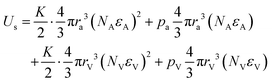 | (5) |
Here,
K is the bulk modulus of the electrolyte material,
ra and
rV are the radii of the cation and vacancy, respectively, and
pa and
pV are the respective pressures externally applied to the interstitial site with the A cation and the vacant lattice associated with the migrated A cation. Note that the pressure
pa consists of external pressure and the stress from the vacant lattice sites associated with migrated A cations and
pV consists of external pressure and the stress from the interstitial A cations.
According to the theory of thermodynamics,36 the change in the Gibbs free energy is
| | | ΔG = kSconf + Us + Ue + ΔHA + ΔHV, | (6) |
with Δ
HA and Δ
HV as the energies needed to form the corresponding interstitial cations and vacancies without stress and electric fields. Using
eqn (2), (4) and (5), we have the change of the Gibbs free energy for the solid electrolyte in the RVE under stress and electric fields as
| |  | (7) |
where
wA and
wV are the energies needed to have an A ion at an interstitial site and a vacancy at a lattice site, respectively, without stress and electric fields. It should be mentioned that
eqn (7) does not include the contribution of ion–ion interaction due to the low concentration of Frenkel defects in ionic crystals. For example, the formation energy of Frenkel defects in LiNbO
3 is ∼1.2 eV per def,
37 which yields ∼3.6 × 10
−7 in atomic ratio for the concentration of Frenkel defects. According to the theory of thermodynamics, the change in the Gibbs free energy is the lowest at an equilibrium state under constant temperature and pressure. This requires that the partial derivatives of the change in the Gibbs free energy with respect to
NA and
NV are equal to zero,
i.e.,
| |  | (8) |
| |  | (9) |
where
σ (=
p1 +
KNAεA =
p2 +
KNVεV) is the resultant hydrostatic stress on the RVE.
Eqn (8) and (9) yield the concentrations of interstitial cations,
Ca, and vacancies,
CV, in the RVE as
| |  | (10) |
| |  | (11) |
with the units of
Ca and
CV being mole per unit volume,

(
N0 is the Avogadro constant) being the Faraday constant,
R being the gas constant, and
ΩA and
ΩV being respective volume changes of the solid electrolyte per mole of interstitial cations and vacancy. The parameter
C0 is the concentration of interstitial cations and the associated vacancies without stress and electric fields.
Eqn (10) uses the condition of
Ca =
CV =
C0 at an equilibrium state for
φ = 0 and
σ = 0. It is evident that the concentrations of interstitial cations and the associated vacancies are exponentially dependent on electric potential and strain energy from the size misfits.
Eqn (10) and (11) reduce the Boltzmann distribution of electrolyte ions in an electric field if there are no contributions from external stress and self-stress.
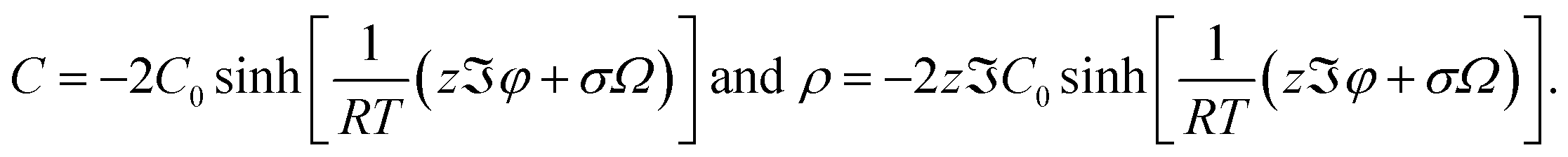
As an approximation used in the work by Chen et al.,24 we have ΩA ≈ ΩV ≈ Ω. Thus, the charge density in the units of Coulomb per unit volume is calculated from eqn (10) and (11) as
| |  | (12) |
Substituting
eqn (12) into Gauss's law,

(
ρ is effective charge density and
ε is the dielectric constant), gives the differential equation as
| |  | (13) |
which is used to determine the spatial distribution of the electric potential.
Eqn (13) is reduced to the Poisson–Boltzmann equation if there is no stress effect,
i.e.,
σ = 0. The linearized form of
eqn (13) is
| |  | (14) |
Here,
εr and
ε0 are the relative dielectric constant and the dielectric constant of the vacuum. Similar to the linear Poisson–Boltzmann equation,
eqn (14) rests on the conditions of low surface potential and small stress with the contributions of higher order terms of (

(
n = 2, 3, 4, …)) being negligible.
For mechanical deformation with small strain, the theory of linear elasticity prevails. The relationship between the displacement vector, u, and the strain tensor, ε, is
| |  | (15) |
Analogous to thermal stress and diffusion-induced stress,
38–41 the constitutive relationships for the elastic deformation of the solid electrolyte induced by interstitial cations and the associated vacancies can be expressed as
| |  | (16) |
where
σ and
I are the stress and unit tensors, respectively, and
E and
ν are Young's modulus and Poisson's ratio of the solid electrolyte, respectively. The term of (
Ca −
CV)
Ω represents the volumetric strain associated with the presence of interstitial cations and the associated vacancies.
The “1/3” comes from the contribution of linear strain components in three orthogonal directions to volumetric strain. It is worth noting that the mean strain in an RVE is generally small due to the low concentration of Frenkel defects even though local strains associated with individual interstitial cations may be large. For electrode materials with large diffusion-induced strains, such as silicon and tin, finite deformation theory needs to be used.
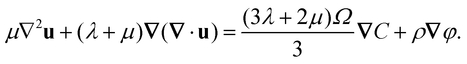
The equilibrium equation at the static state is
in which the second term on the left side represents the electric force on the solid electrolyte. Letting
C = (
Ca −
CV) and using
eqn (15)–(17), we obtain
| |  | (18) |
For a detailed derivation, see Appendix. According to
eqn (10)–(12) and (18) can be rewritten as
| |  | (19) |
Eqn (13) and (19) together with the corresponding boundary conditions form the basis to determine the spatial distributions of electric potential and electrolyte ions as well as the stress field at the equilibrium state. It is evident that there exists coupling between the electric field and stress field. Note that the resultant hydrostatic stress,
σ, is equal to Tr(
σ)/3.
Under the conditions of low surface potential and small stress, eqn (19) is simplified to
| |  | (20) |
which is a set of nonlinear partial differential equations.
One-dimensional problem
To understand the characteristics of the space charge zone around electrode, we consider a one-dimensional problem. A symmetrical binary solid electrolyte is sandwiched between two planar electrodes with an electric potential difference of φ0. The contact between the solid electrolyte and the electrodes is frictionless. The distance between the electrodes is L. For simplification, the analysis is limited to the linearized form of eqn (13). Using eqn (14) and (20), the first order of φ becomes| |  | (21) |
| |  | (22) |
with u as the displacement in the x-direction. Here, the parameter of κ is defined as| |  | (23) |
The resultant hydrostatic stress, σ, is equal to σx/3 with σx as the normal stress in the x-direction. The boundary conditions are| | | φ|x=0 = φ0 and φ|x=L = 0, | (24) |
The general solutions of eqn (21) and (22) are| |  | (26) |
| |  | (27) |
with A1, A2, B1 and B2 being constants determined by the boundary conditions of 24 and 25. The analytical formulations of A1, A2, B1 and B2 are given in Appendix. Using eqn (26) and (27) and the analytical formulations of A1, A2, B1 and B2, we obtain| |  | (28) |
| |  | (29) |
| |  | (30) |
| |  | (31) |
It is interesting to note that the uniaxial stress uniformly distributes in the solid electrolyte. No stress gradient is present provided that the contribution of electric force is negligible and the contact between the solid electrolyte and the electrodes is frictionless.
Results and discussion
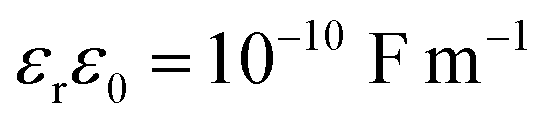
There are various solid electrolytes available for lithium-ion batteries, including oxide electrolytes, sulfide electrolytes, borohydrides. Among them, niobium pentoxide (Nb2O5) exhibited great potential as an anode material with its fast rate and good cyclability.42 The following numerical values are focused on a solid electrolyte of LixNb2O5 of 0.1 μm in thickness, which is sandwiched between two planar electrodes. The potential difference between the two electrodes is 0.01 V. The mobile species are interstitial Li+ ions and associated excess “vacancies”, with z = 1, C0 = 10 mol m−3, Ω = 5 × 10⁻⁶ m3 mol−1, v = 0.3, K = 50 GPa, and  according to the work by Chen et al.24 in the analysis of the space charge zone in a bent-sandwiched beam from interstitial Li+ ions in LixNb2O5 at T = 300 K. Note that there is only a 3% increase in the c-axis lattice constant for the lithiation of T-Nb2O5 in the voltage range of 1.2–3.0 V vs. Li/Li+.43 Thus, the theory of linear elasticity prevails.
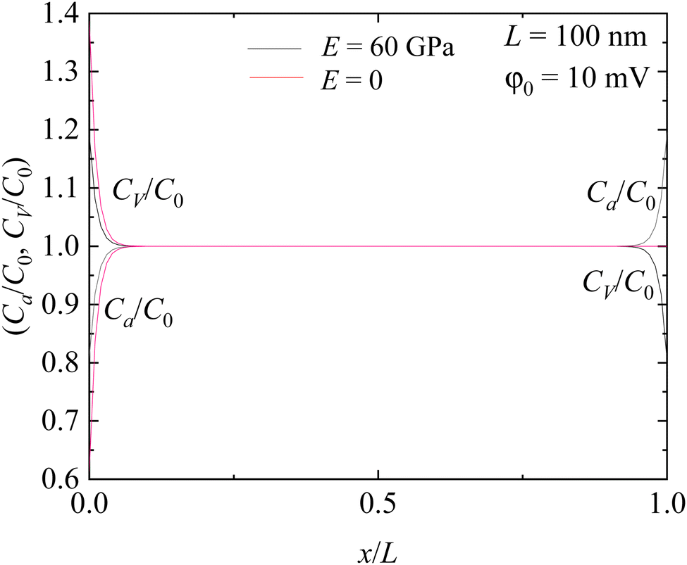
Fig. 2 depicts the spatial distribution of interstitial Li+ ions and associated “vacancies” in the solid electrolyte. At the electrode with a higher electric potential (x = 0), there is a depletion of Li ions; on the other side (x = L), there is a depletion of the associated “vacancies”. Such behavior can be attributed to the interaction between the electric field and electric charge. With the electrode at x = 0 having a higher potential and the electrode at x = L having a lower potential, the direction of the electric field points to the x-direction, which causes the accumulation of interstitial Li+ ions near the electrode at x = L and the associated “vacancies” near the electrode at x = 0. The thickness of the depletion (accumulation) zones of interstitial Li+ ions (associated “vacancies”) is ∼18 nm for the solid electrolyte with a 100 nm thickness. Between the depletion (accumulation) zones, both the interstitial Li+ ions and the associated “vacancies” exhibit nearly uniform distribution, which is almost the same as the one without the action of electric and stress fields.
 |
| | Fig. 2 Spatial distribution of interstitial Li+ ions and associated “vacancies” in the solid electrolyte. | |
For comparison, the results without the stress effect (E = 0) are also included in the Figure. Similar to the case with the stress effect, there exists a depletion of Li+ ions and an accumulation of the associated “vacancies” near x = 0. However, the stress effect reduces the extent of the depletion of Li+ ions and increases the accumulation of the associated “vacancies”. Near x = L, there is nearly no accumulation of Li+ ions. Such behavior can be attributed to the dependence of A2 and B2 on Young's modulus of the solid electrolyte. Without the stress effect, B2/A2 = −e2κL. For the geometrical configuration of L = 0.1 μm, there is |B2| ≫ |A2|. Thus, the solid electrolyte can be approximated as semi-infinite.
Fig. 3 depicts the spatial distribution of the net charge density in the solid electrolyte. Near the electrode at x = 0, the net charge is negative; near the electrode at x = L, the net charge is positive. Away from the depletion (accumulation) zones, the net charge is nearly null. The effects of both the electric field and stress field are mainly limited to the regimes near the electrodes. Thus, the depletion (accumulation) zones represent the space-charge zone. It should be pointed out that both A2 and B2 are proportional to the potential difference, indicating that the net charge density in the depletion (accumulation) zones is proportional to the potential difference. However, such a proportionality is based on the condition of low surface potential and small stress. Otherwise, no closed-form solutions are available, and numerical methods are needed to determine the net charge density in the depletion (accumulation) zone.
 |
| | Fig. 3 Spatial distribution of charge density in the solid electrolyte. | |
Fig. 4 shows the spatial distribution of electric potential in the solid electrolyte. It is interesting to note that the electric potential exhibits similar distribution to that of the charge density, except that the electric potential decreases with the increase of x, reaches a “plateau” of φ = 0.5φ0, and then decreases with the further increase of x. Such behavior is consistent with the potential difference between two electrodes with the electrode at x = 0 having a higher potential than the one at x = L. The potential “plateau” corresponds to the region with nearly null net charge density, as shown in Fig. 3. No electric field is presented in the “plateau” region. The local electric field only occurs near the electrodes, in accord with the presence of the space charge zone.
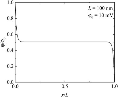 |
| | Fig. 4 Spatial distribution of electric potential in the solid electrolyte. | |
To examine if the size of the space charge zone is dependent on the thickness of solid electrolyte, we performed numerical calculations of the net charge density for the thickness of solid electrolyte within the range of 10 nm to 1 μm. Fig. 5 shows the spatial distribution of net charge density in the solid electrolytes of different thicknesses. Note that the abscissa in Fig. 5 is normalized by the corresponding thickness. In general, the size of the space charge zone is a function of the thickness of solid electrolyte. For a solid electrolyte of 10 nm, the space charge zone nearly spans over the entire solid electrolyte, as revealed in Fig. 5. Increasing the thickness of solid electrolyte leads to the presence of a region with nearly null net charge density, whose size increases with the greater thickness of solid electrolyte.
 |
| | Fig. 5 Spatial distribution of net charge density in the solid electrolytes of different thicknesses. | |
Let x0 be the size of the space charge zone, which is determined by the solution of ρ(x) = 0. Fig. 6 shows the variation in the size of space charge zone, x0, with the thickness of solid electrolyte. The size of the space charge zone increases linearly with increasing the thickness of solid electrolyte. Using linear regression to fit the data in Fig. 6, we obtain a slope of 0.5. This result indicates that the space charge zone actually spans over the whole solid electrolyte in a way similar to the case with L = 10 nm, as shown in Fig. 5. However, this is significantly different from the intuitive results presented in Fig. 5.
 |
| | Fig. 6 Variation in the size of the space charge zone, which is determined by the solution of ρ(x) = 0, with the thickness of the solid electrolyte. | |
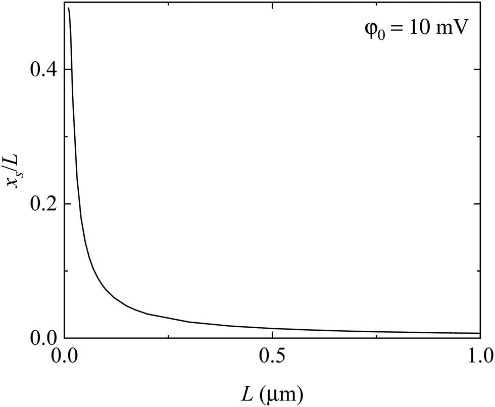
To be consistent with the visual observation from Fig. 5, we let xs be the nominal size of the space charge zone. The condition for the determination of xs is
| | | A2eκx + B2e−κx = 10−5. | (32) |
Fig. 7 shows the variation of the nominal size of the space charge zone, which is determined by
eqn (32), with the thickness of the solid electrolyte. In contrast with the results shown in
Fig. 6, the nominal size of the space charge zone is a nonlinear function of the thickness of the solid electrolyte. The ratio of the nominal size of the space charge zone to the thickness of the solid electrolyte is a decreasing function of the thickness of the solid electrolyte. Increasing the thickness of the solid electrolyte eventually leads to the separation of the space charge zones.
 |
| | Fig. 7 Variation in the nominal size of the space charge zone, which is determined by the solution of A2eκx + B2e−κx = 10−5, with the thickness of the solid electrolyte. | |
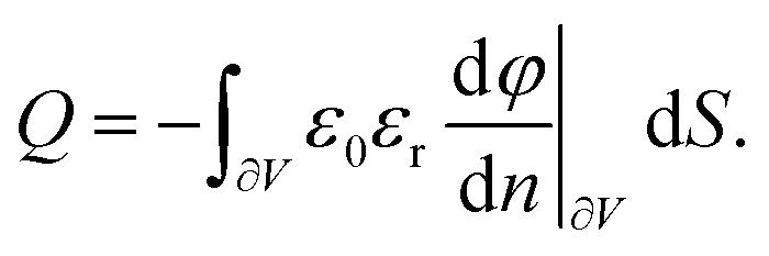
According to the above results, it is expected that there is accumulation/adsorption of a layer of charges (interstitial cations) at the electrode. Such behavior is similar to the Stern layer for liquid electrolyte. This allows for the storage of energy in a capacitive form, similar to the electric double layer.26 The charge density of the layer of charges adsorbed to the electrode is calculated as
| |  | (33) |
where ∂
V represents the surface of the electrode. From
eqn (33), the total charge stored in the adsorption layer,
Q, is calculated as
| |  | (34) |
Using
eqn (27) and (34), the integral capacitance of the adsorption layer per unit area is found as
| |  | (35) |
It is evident that the integral capacitance is dependent on the concentration of interstitial cations at the equilibrium state as well as the elastic constant of solid electrolyte.
For κL ≪ 1, there are (1 + e2κL) ≈ 2, (1 − e2κL) ≈ −2κL, and (1 − eκL) ≈ −κL. Thus, eqn (35) is simplified as
| |  | (36) |
which is the same as the capacitance of a parallel capacitor.
Space charge zones are thought to allow a third (additional) mode of charge storage, i.e., interfacial storage of Li+ ions in LIBs, in addition to the well-known bulk storage of Li+ ions (Li intercalation and Li reaction (Li alloying) mechanisms).17–19 In the extreme case, a composite of two phases can store Li+ ions, although none of the constituent phases can store Li.17 LiNbO3 is of particular interest.14 From the class of perovskites, LiNbO3 is one of the most technologically important materials in science and technology due to its favorable combination of pyroelectric, piezoelectric, electrocaloric, acousto-optic, giant-photovoltaic, ferroelectric, electrooptic, photorefractive, and nonlinear optical properties, and not least due to its energy conversion properties combined with a simple fabrication technique and low fabrication cost.14 In addition, the Li mobility in LiNbO3 generally plays a critical role in the successful implementation of LiNbO3's versatile properties in the performance of LiNbO3-based devices.14
Superlattices combining amorphous nano-sized LiNbO3 layers with nano-sized Si spacer layers, which are the next generation of high-capacity LIB active materials,44 have been found to increase the ability to transport Li by up to five orders of magnitude.45,46 Recent unpublished measurements of Li transport show that the huge transport capability of Li+ ions depends not only on the thickness of the Si spacer layer, but also on the thickness of the LiNbO3 spacer layers. Multilayers combining amorphous LiNbO3 layers with spacers other than Si have also been reported.47 It was calculated that the space charge layers extend over the whole Li–Nb–O film thickness depending on the thickness of the Li–Nb–O based film. This result may be the origin of the strongly enhanced Li transport measured experimentally in the LiNbO3/Si superlattice.
It should be noted that an electric field can occur if the superlattices contain layers of piezoelectric material (e.g., LiNbO3). When these layers are under stress, a piezoelectric electric field can appear over the spacer layer, which can promote or suppress Li+ ion transport. This is important for self-charging LIBs, which hybridize mechanical energy harvesting and ion storage into one process.14 The electric field can also affect the electronic structure of the spacer layer and change the property in the superlattice.
Summary
We have incorporated the contributions of strain energy and electric energy to the Gibbs free energy for a solid electrolyte consisting of interstitial cations and associated “vacancies” in the framework of linear elasticity. Using the change of the Gibbs free energy and the equilibrium conditions in stress and electric fields, the dependences of the concentrations of interstitial cations and associated “vacancies” on the stress and electric fields were formulated analytically. Combining Gauss's law, elastic constitutive relationships, and mechanical equilibrium equations yields a nonlinear and coupling system for the determination of the spatial distributions of interstitial cations, associated “vacancies”, and stress and electric fields. Under small stress and electric fields, the nonlinear and coupling system can be reduced to a linear and coupling system.
For a solid electrolyte sandwiched between two parallel electrodes in a way similar to a parallel capacitor, analytical solutions of the charge density, stress and electric fields have been obtained for the linear and coupling system with frictionless contact between the solid electrolyte and the electrodes. The solid electrolyte is subjected to constant stress. The numerical results reveal that there is a layer of charges (interstitial cations or charged “vacancies”) in the associated electrode corresponding to the space charge zone surrounding the electrode. The space charge zone can span over the whole solid electrolyte if the condition of null net charge density is used. Using a non-null (a very small) net charge density in the determination of the size of the space charge zone, which is in accord with the visual observation of the distribution of net charge density, the size of the space charge zone is determined numerically. The ratio of the nominal size of the space charge zone to the thickness of the solid electrolyte is a decreasing function of the thickness of the solid electrolyte. The presence of the space charge zone allows for the storage of energy in a capacitive form, similar to the Stern layer for liquid electrolytes, and the integral capacitance is dependent on the concentration of interstitial cations at the equilibrium state as well as elastic constants of the solid electrolyte.
This work has developed a new nonlinear and coupling system to analyze the interface behavior of heterogeneous structures, including the interface between solid electrolyte and electrode. It provides the basis for analyzing the effects of the space charge zone on the energy storage of multilayer structures to be used in metal-ion systems. The approach presented in this work can be extended to study the multi-field coupling problems in solid oxide fuel cells, mixed halide quantum dots, and transducers.
Data availability
The authors declare that the data supporting the findings of this study are available within the paper.
Conflicts of interest
There are no conflicts to declare.
Appendix
Using the Lamé parameters, λ and μ, eqn (16) can be written in an index form as follows:| |  | (A1) |
with δij as the Kronecker delta. The equilibrium eqn (17) in an index form can be written as follows:| |  | (A2) |
Substituting eqn (A1) in eqn (A2) yields the following equation:| |  | (A3) |
which can be rewritten in a vector form:| |  | (A4) |
Using the correlations between (λ, μ) and (E, v), we can reduce eqn (A4) to (18). Note that there are| |  | (A5) |
Substituting eqn (A5) in eqn (A4) yields eqn (19).
The analytical formulations of A1, A2, B1 and B2 are given below.
| |  | (A6) |
| |  | (A7) |
| |  | (A8) |
| |  | (A9) |
Acknowledgements
The authors thank the National Science Foundation (NSF) for the support (award number (FAIN): CBET-2438033) and the German Science Foundation (DFG) for the support under contract HU 2170/3-1 (project number 540944754), as part of the NSF-DFG Lead Agency Activity in Measurements of Interfacial Systems at Scale with in situ and Operando Analysis (NSF-DFG MISSION initiative).
References
- N. J. de Klerk and M. Wagemaker, ACS Appl. Energy Mater., 2018, 1, 5609–5618 CrossRef CAS PubMed.
- C. Yu, S. Ganapathy, E. R. V. Eck, H. Wang, S. Basak, Z. Li and M. Wagemaker, Nat. Commun., 2017, 8, 1086 CrossRef PubMed.
- G. Bucci, B. Talamini, A. Renuka Balakrishna, Y.-M. Chiang and W. C. Carter, Phys. Rev. Mater., 2018, 2, 105407 CrossRef.
- E. L. Molel, J. A. Lewis, S. E. Sandoval, D. L. Nelson, M. T. McDowell and T. F. Fuller, J. Electrochem. Soc., 2024, 171, 103504 CrossRef CAS.
- S. Wang, H. Xu, W. Li, A. Dolocan and A. Manthiram, J. Am. Chem. Soc., 2018, 140, 250–257 CrossRef CAS PubMed.
- S. Lou, Q. Liu, F. Zhang, Q. Liu, Z. Yu, T. Mu, Y. Zhao, J. Borovilas, Y. Chen and M. Ge, Nat. Commun., 2020, 11, 5700 CrossRef CAS PubMed.
- L. Wang, R. Xie, B. Chen, X. Yu, J. Ma, C. Li, Z. Hu, X. Sun, C. Xu and S. Dong, Nat. Commun., 2020, 11, 5889 CrossRef CAS PubMed.
- S.-H. Chen and C.-C. Chen, Phys. Chem. Chem. Phys., 2024, 26, 24689–24698 RSC.
- K. Yamamoto, Y. Iriyama, T. Asaka, T. Hirayama, H. Fujita, C. A. Fisher, K. Nonaka, Y. Sugita and Z. Ogumi, Angew. Chem., Int. Ed., 2010, 49, 4414–4417 CrossRef CAS PubMed.
- K. Yamamoto, R. Yoshida, T. Sato, H. Matsumoto, H. Kurobe, T. Hamanaka, T. Kato, Y. Iriyama and T. Hirayama, J. Power Sources, 2014, 266, 414–421 CrossRef CAS.
- Y. Aizawa, K. Yamamoto, T. Sato, H. Murata, R. Yoshida, C. A. Fisher, T. Kato, Y. Iriyama and T. Hirayama, Ultramicroscopy, 2017, 178, 20–26 CrossRef CAS PubMed.
- Y. Nomura, K. Yamamoto, T. Hirayama, S. Ouchi, E. Igaki and K. Saitoh, Angew. Chem., 2019, 131, 5346–5350 CrossRef.
- H. Masuda, N. Ishida, Y. Ogata, D. Ito and D. Fujita, Nanoscale, 2017, 9, 893–898 RSC.
- E. Hüger, L. Riedel, J. Zhu, J. Stahn, P. Heitjans and H. Schmidt, Batteries, 2023, 9, 244 CrossRef.
- J. Maier, Nat. Mater., 2005, 4, 805–815 CrossRef CAS PubMed.
- L. A. Haverkate, W. K. Chan and F. M. Mulder, Adv. Funct. Mater., 2010, 20, 4107–4116 CrossRef CAS.
- L. J. Fu, C. C. Chen, D. Samuelis and J. Maier, Phys. Rev. Lett., 2014, 112, 208301 CrossRef.
- C.-C. Chen, L. Fu and J. Maier, Nature, 2016, 536, 159–164 CrossRef CAS PubMed.
- R. Usiskin and J. Maier, Adv. Energy Mater., 2021, 11, 2001455 CrossRef CAS.
- S. Braun, C. Yada and A. Latz, J. Phys. Chem. C, 2015, 119, 22281–22288 CrossRef CAS.
- M. Landstorfer, S. Funken and T. Jacob, Phys. Chem. Chem. Phys., 2011, 13, 12817–12825 RSC.
- N. J. J. de Klerk and M. Wagemaker, ACS Appl. Energy Mater., 2018, 1, 5609–5618 CAS.
- M. C. Göbel, G. Gregori and J. Maier, Phys. Chem. Chem. Phys., 2014, 16, 10214–10231 RSC.
- C. C. Chen, Y. K. Yin, S. D. Kang, W. Cai and W. C. Chueh, Phys. Chem. Chem. Phys., 2021, 23, 23730–23740 RSC.
- C. L. Xiao, C. C. Chen and J. Maier, Phys. Chem. Chem. Phys., 2022, 24, 11945–11957 RSC.
- A. A. Kornyshev, J. Phys. Chem. B, 2007, 111, 5545–5557 CrossRef CAS PubMed.
- G. J. Nelson, B. N. Cassenti, A. A. Peracchio and W. K. Chiu, J. Power Sources, 2012, 205, 48–56 CrossRef CAS.
- M. Chen, X. Xie, J. Guo, D. Chen and Q. Xu, J. Mater. Chem. A, 2020, 8, 12566–12575 RSC.
- D. Yuan, Z. Han, F. Cao, X. Liu, M. Liu, L. Zhang, S. Cao, J. Li, T. Zeng and Y. Chen, ACS Appl. Electron. Mater., 2024, 6, 8455–8462 CrossRef CAS.
- F. Yang, Phys. Scr., 2024, 99, 025937 CrossRef CAS.
- A. F. Gualdron-Reyes, J. Rodriguez-Pereira, E. Amado-Gonzalez, J. Rueda-P, R. Ospina, S. Masi, S. J. Yoon, J. Tirado, F. Jaramillo and S. Agouram, ACS Appl. Mater. Interfaces, 2019, 12, 914–924 CrossRef PubMed.
- J. Lewiner, IEEE Trans. Dielectr. Electr. Insul., 2010, 17, 1096–1105 Search PubMed.
- L. Barhoumi, A. Baraket, N. M. Nooredeen, M. B. Ali, M. N. Abbas, J. Bausells and A. Errachid, Electroanalysis, 2017, 29, 1586–1595 CrossRef CAS.
-
L. Landau and M. Lifshitz, Electrodynamics of continuous media, Pergamon Press, Oxford, 2nd edn, 1984 Search PubMed.
-
M. H. Sadd, Elasticity: theory, applications, and numerics, Academic Press, New York, 2009 Search PubMed.
-
D. A. Porter and K. E. Easterling, Phase transformations in metals and alloys, CRC Press, New York, 2009 Search PubMed.
- H. Xu, D. Lee, S. B. Sinnott, V. Dierolf, V. Gopalan and S. R. Phillpot, J. Condens Matter Phys., 2010, 22, 135002 CrossRef PubMed.
-
N. Noda, Thermal stresses, Taylor & Francis Group, New York, 2nd edn, 2018 Search PubMed.
-
M. R. Eslami, J. Eslami and M. Jacobs, Buckling and postbuckling of beams, plates, and shells, Springer, New York, 2018 Search PubMed.
- F. Yang, J. Electrochem. Soc., 2021, 168, 040520 CrossRef CAS.
- F. Yang, Mater. Sci. Eng., A, 2005, 409, 153–159 CrossRef.
- J. Lin, S. Zhao, T. G. Tranter, Z. Zhang, F. Peng, D. Brett, R. Jervis and P. R. Shearing, Electrochim. Acta, 2023, 443, 141983 CrossRef CAS.
- S. C. Wechsler, A. Gregg and M. Stefik, Adv. Funct. Mater., 2024, 34, 2312839 CrossRef CAS.
- K. Zhang, E. Hüger, Y. Li, H. Schmidt and F. Q. Yang, Batteries, 2023, 9, 105 CrossRef CAS.
- E. Hüger and H. Schmidt, J. Phys. Chem. C, 2018, 122, 28528–28536 CrossRef.
- E. Hüger, J. Stahn, P. Heitjans and H. Schmidt, Phys. Chem. Chem. Phys., 2019, 21, 16445–16450 RSC.
- E. Hüger, L. Dörrer, R. Yimnirun, J. Jutimoosik, J. Stahn and A. Paul, Phys. Chem. Chem. Phys., 2018, 20, 23233–23243 RSC.
|
| This journal is © the Owner Societies 2025 |
Click here to see how this site uses Cookies. View our privacy policy here. 
 Open Access Article
 This Open Access Article is licensed under a Creative Commons Attribution-Non Commercial 3.0 Unported Licence
 *a and
Erwin
Hüger
*a and
Erwin
Hüger


 (N0 is the Avogadro constant) being the Faraday constant, R being the gas constant, and ΩA and ΩV being respective volume changes of the solid electrolyte per mole of interstitial cations and vacancy. The parameter C0 is the concentration of interstitial cations and the associated vacancies without stress and electric fields. Eqn (10) uses the condition of Ca = CV = C0 at an equilibrium state for φ = 0 and σ = 0. It is evident that the concentrations of interstitial cations and the associated vacancies are exponentially dependent on electric potential and strain energy from the size misfits. Eqn (10) and (11) reduce the Boltzmann distribution of electrolyte ions in an electric field if there are no contributions from external stress and self-stress.

 (ρ is effective charge density and ε is the dielectric constant), gives the differential equation as

 (n = 2, 3, 4, …)) being negligible.


 according to the work by Chen et al.24 in the analysis of the space charge zone in a bent-sandwiched beam from interstitial Li+ ions in LixNb2O5 at T = 300 K. Note that there is only a 3% increase in the c-axis lattice constant for the lithiation of T-Nb2O5 in the voltage range of 1.2–3.0 V vs. Li/Li+.43 Thus, the theory of linear elasticity prevails.