
 Open Access Article
 This Open Access Article is licensed under a
 Creative Commons Attribution 3.0 Unported Licence
Different mechanisms for lanthanide(III) sensitization and Yb-field-induced single-molecule magnet behaviour in a series of pentagonal bipyramidal and octahedral lanthanide complexes with axial phosphine oxide ligands†
Hadjer
Allia
 a,
Ana
Rodríguez-Expósito
b,
María A.
Palacios
*a,
Juan-Ramón
Jiménez
a,
Albano N.
Carneiro Neto
c,
Renaldo T.
Moura
Jr.
d,
Fabio
Piccinelli
e,
Amparo
Navarro
b,
María Mar
Quesada-Moreno
*b and
Enrique
Colacio
*a
a,
Ana
Rodríguez-Expósito
b,
María A.
Palacios
*a,
Juan-Ramón
Jiménez
a,
Albano N.
Carneiro Neto
c,
Renaldo T.
Moura
Jr.
d,
Fabio
Piccinelli
e,
Amparo
Navarro
b,
María Mar
Quesada-Moreno
*b and
Enrique
Colacio
*a
aDepartamento de Química Inorgánica, Facultad de Ciencias, Campus Fuentenueva, Universidad de Granada, 18071-Granada, Spain. E-mail: mpalacios@ugr.es; ecolacio@ugr.es
bDepartamento de Química Física y Analítica, Facultad de Ciencias Experimentales, Campus Las Lagunillas, Universidad de Jaén, 23071-Jaén, Spain. E-mail: mqmoreno@ujaen.es
cDepartment of Physics, University of Aveiro, 3810-193-Aveiro, Portugal
dAcademic Unit of Cabo de Santo Agostinho, Federal Rural University of Pernambuco (UFRPE), Cabo de Santo Agostinho 54518-430, Brazil
eLuminescent Materials Laboratory, DB, University of Verona, and INSTM, Verona 37134, Italy
First published on 25th April 2025
Abstract
Seven mononuclear lanthanide complexes have been isolated and structurally characterised. Four of them are cationic, whose charges are balanced by chloride counteranions, and exhibit pentagonal bipyramidal coordination geometry, whereas the rest of them are neutral and display octahedral coordination environment. In all cases, the coordination sphere of the LnIII ions consists of two di(1-adamantyl)benzylphosphine oxide ligands in axial positions, whereas in the equatorial plane the former contains a chloride and four water molecules and the latter a solvent molecule and three chloride ligands. We report a detailed photophysical investigation, including time-dependent density functional theory (TD-DFT) calculations and intramolecular energy transfer (IET) analysis, which reveals two distinct lanthanide sensitization mechanisms. Compound-specific energy transfer pathways occur through either the S1 or T1 states, as supported by calculated IET rates and resonance with lanthanide acceptor transitions. In addition, dc and ac magnetic properties were measured on complexes 1 and 2, showing that compound 1 behaves as a bi-functional compound, exhibiting field-induced single molecule magnet behaviour together with YbIII-centred NIR luminescence. The relaxation of the magnetization in this pentagonal bipyramidal complex takes place through Raman and direct processes, as supported by ab initio calculations.
Introduction
Lanthanides are widely recognized for their unique electronic properties, attributed to the configuration of their 4f orbitals, making them valuable for various technological applications, including magneto–luminescent materials and imaging agents.1–3 The 4f electrons are shielded by the filled 5s and 5p shells, which limits their interaction with the external environment, making the luminescence and magnetic properties intrinsic to the lanthanide ions.1–3 For instance, they exhibit sharp emission bands, long-lived excited states and/or significant pseudo Stokes shift. However, lanthanide ions display low molar extinction coefficients because their f–f transitions are Laporte forbidden. Thus, direct excitation leads to weak photoluminescence.4,5One strategy to overcome their weak luminescence is through the “antenna effect”, which uses highly absorbing organic ligands4,6 or d-block chromophores7–9 to sensitize the lanthanide center via efficient energy transfer. In the case of organic chromophores, sensitization occurs when the lowest excited state of the lanthanide is populated through energy transfer from the T1 state of the antenna. While energy transfer can also take place from the S1 state10–12 or via other pathways, such as a charge transfer state,13 energy transfer from the T1 state is generally accepted as the primary mechanism due to its longer lifetime.1–3 This indirect sensitization method has been proven to be highly efficient when both the antenna and the lanthanide ion are in close proximity within coordination complexes that remain stable over the duration of the luminescence experiment. This property makes luminescent lanthanides suitable for live-cell and in vivo imaging.8,14
Furthermore, the combination of luminescence with another physical property in a single crystalline solid enables the development of multifunctional materials, featuring the coexistence of two or more electronic properties of interest (such as luminescence and magnetism).15,16 These magneto–luminescent materials hold potential applications in optoelectronics, sensors, and various biological fields, including luminescent markers, neurobiology, cancer research, stem cell biology, and the study of infectious diseases.17
Single molecule magnets (SMMs) are metal coordination compounds that can, below a critical temperature known as blocking temperature (TB), block the magnetization through an anisotropy barrier (Ueff) for long periods of time in the absence of an external magnetic field.18–22 In other words, they display magnetic storage at the nanometer scale. SMMs have been extensively studied due to their significant technological potential in molecular spintronics, ultra-high-density data storage, and as spin qubits in quantum information technologies.23–25 However, the primary challenge in the magnetism field remains achieving a magnetic memory effect at high temperatures, while simultaneously ensuring high thermal air and humidity stability.
In the early stages of SMMs discovery, the focus was primarily on 3d SMMs, particularly Mn-based polynuclear compounds.26 However, since the first report of {Tb(Pc)2},27 Ln-based complexes have made significant advancements in magnetic performance, owing to their inherent large magnetic moments and magnetic anisotropy, which are further enhanced by the surrounding ligand field. This includes complexes such as DyIII,20,28–31 TbIII,32,33 HoIII,34 and ErIII,35,36 which have all contributed to notable progress in this research field.
The DyIII mononuclear [Dy(C5Me5(CpiPr5))][B(C6F5)4]37 and the mixed-valence DyIIIDyII dinuclear [Dy2I3(CpiPr5)2] metallocene29 compounds have achieved remarkable performance with Ueff values of 2217 K and 2347 K, respectively, and a TB of 80 K in both cases, surpassing the temperature of liquid nitrogen. This breakthrough paves the way for potential commercial applications of these molecules in technology. However, their major limitation is their extreme instability. Mononuclear SMMs with D5h geometry occupy a relevant place38 because they display in most of the cases (there are some exceptions39–42) thermal air and humidity stability, with Ueff and TB value as high as 1162 K43 and 36 K44 in DyIII SIMs (single ion magnets), respectively.
It should be noted that the combination of SMM and luminescence in the same compound to give magneto–luminescent multifunctional materials45,46 has attracted much attention not only because these materials can exhibit distinct physical properties, but also because they can display a synergistic effect due to the interaction of both properties.17,47,48 In fact, some luminescent SMMs show emission switching under magnetic field,49 and field-induced YbIII SMMs show potential and luminescent thermometers.15,17,47,48,50 Moreover, these systems are useful to establish an experimental correlation experimental between the emissions, the electronic structure and the relaxation dynamics.51
In view of the previous considerations, we focused our efforts on the preparation of a series of multifunctional mononuclear lanthanide complexes with bipyramid pentagonal geometry, luminescent properties and SMM or field-induced SMM behaviour. Their synthesis rendered two different type of coordination compounds, one of general formula [Ln(OPAd2Bz)2(H2O)4Cl]Cl2·xTHF·zH2O (Ln = YbIII, x = 2, z = 0 (1); Ln = TbIII, x = 3, z = 1.5 (2); Ln = GdIII, x = 1.8, z = 0 (3); Ln = DyIII, x = 2, z = 0 (4)), where the lanthanide ion exhibits a pentagonal bipyramidal coordination geometry and, other of general formula [Ln(OPAd2Bz)2(z)Cl3]·xTHF (Ln = EuIII, z = H2O, x = 1.4 (5); Ln = GdIII, z = THF, x = 0 (6); Ln = DyIII, z = THF, x = 0 (7)), in which the LnIII atom presents an octahedral coordination environment. We describe here the synthesis and X-ray crystal structures of compounds 1–3, 5 and 6, as well as an in-depth photophysical study of all the complexes, in which we also include a similar complex of formula [Dy(OPAd2Bz)2(H2O)4Br]Br2·4THF (8) prepared by some of us,52 whereas dc and ac magnetic properties are displayed for 1 and 2. Magnetic properties and structures of compounds 4, 7 and 8 are reported in ref. 52 (compound 8) and ref. 53 (compounds 4 and 7). In this work, we used comprehensive spectroscopic characterization and state-of-the-art time-dependent density functional theory (TD-DFT) calculations to investigate the photophysical properties and lanthanide sensitization mechanisms of lanthanide complexes 1–8. Notably, our findings demonstrate that several pathways contribute to the sensitization of lanthanide emission in this series of compounds.
Experimental
General procedures
The analytical reagents were purchased from commercial sources and used without further purification. The ligand di(1-adamantyl)benzylphosphine oxide was prepared according to a previously described procedure.52![[double bond, length as m-dash]](https://www.rsc.org/images/entities/char_e001.gif) C); 1500–1300 δ(C–H); 1200–1100, ν(PO); 700, ν(P–C).
C); 1500–1300 δ(C–H); 1200–1100, ν(PO); 700, ν(P–C).
After several days, suitable colourless crystals for X-ray diffraction were obtained by slow evaporation of the mother solution. Yield: 29%. Anal. Calcd for C66H109Cl3TbO10.5P2, C: 56.71%, H: 7.86%. Found C: 56.61%, H: 8.02%. IR (cm−1): 2900–2800, ν(C–H); 1600–1500, ν(CC); 1500–1300 δ(C–H); 1200–1100, ν(PO); 700, ν(P–C).
C); 1500–1300 δ(C–H); 1200–1100, ν(PO); 700, ν(P–C).
C); 1500–1300 δ(C–H); 1200–1100, ν(PO); 700, ν(P–C).
C); 1500–1300 δ(C–H); 1200–1100, ν(PO); 700, ν(P–C).
C); 1500–1300 δ(C–H); 1200–1100, ν(PO); 700, ν(P–C).
C); 1500–1300 δ(C–H); 1200–1100, ν(PO); 700, ν(P–C).
Physical measurements
Elemental analyses were performed on a Fisons-Carlo Erba analyser model EA 1108 and IR spectra were recorded on a Bruker Tensor 27 spectrophotometer by using ATR detection.X-ray powder diffraction (XRPD) spectra were registered on a Bruker D8 DISCOVER using CuKα (λ = 1.5406 Å) radiation and DECTRIS PILATUS3R 100K-A detector, from 5 to 50° (2θ) at a scanning rate of 0.02° 2θ min−1 at the “Centro de Instrumentación Científica” (University of Granada). The experimental X-ray powder spectra of 5–6 are, practically coincident with the theoretical ones, just indicating that the compounds are pure and homogeneous (Fig. S1, ESI†). However, the X-ray powder diffractograms of 1–3 do not match exactly with those generated from the corresponding X-ray structures, but these small differences are due to the quick loss of the crystallization solvent molecules in these crystals (Fig. S2, ESI†). The experimental powder X-ray diffractograms of 4 and 7 match well with the theoretical ones and they are superimposable with those of 1 and 6, respectively, as expected for isostructural compounds. In Fig. S1 and S2 (ESI†) it can be seen that the diffractograms present the same diffraction peaks, thus confirming that 4 and 1 (and 7 and 6) are isostructural.
Variable-temperature (2–300 K) magnetic susceptibility measurements were carried out on polycrystalline samples under an applied field of 1000 Oe using a DynaCool PPMS-9 physical properties measurement equipment at the CIC-UGR. Alternating-current (ac) susceptibility measurements in the temperature range of 2–15 (1) or 2–20 (2) were performed in a PPMS-9 equipment in the 50–10![[thin space (1/6-em)]](https://www.rsc.org/images/entities/char_2009.gif) 000 Hz (1) or 100–10000 Hz (2) frequency range, using an oscillating field of Hac = 3 Oe. The magnetic susceptibility values were corrected for the diamagnetism of the molecular constituents and sample holder.
000 Hz (1) or 100–10000 Hz (2) frequency range, using an oscillating field of Hac = 3 Oe. The magnetic susceptibility values were corrected for the diamagnetism of the molecular constituents and sample holder.
The UV-Vis spectrum of the ligand in solution was recorded on an AGILENT CARY-100 spectrophotometer. In addition, the solid UV-VIS-NIR of the ligand and compounds 1–8 were measured on a VARIAN CARY-5E spectrophotometer at the CIC-UGR.
Emission and excitation spectra were measured on a UV-VIS-NIR HORIBA QuantaMaster-8000 spectrofluorometer equipped with a UV-VIS PMT PPD850C Detector (210–870 nm) (2–8) or NIR PMT R5509-73 detector (300–1700 nm) (1) and a continuous Xenon Short Arc Lamp (190–2000 nm, USHIO). All the spectra (emission and excitation) were corrected with real-time correction functions.
Time correlated single photon counting (TCSPC) lifetime measurements were performed using a flash lamp (1 μs pulse, HORIBA Scientific).
Single-crystal structure determinations
Suitable crystals of 1–3 and 5–6 were mounted on a glass fibre and used for data collection. X-ray diffraction data were collected at 100 K using a Bruker D8 Venture diffractometer (MoKα radiation, λ = 0.71073 Å) outfitted with a PHOTON 100 detector. Unit-cell parameters were determined and refined on all observed reflections using APEX2 software.54 Correction for Lorentz polarization and absorption were applied by SAINT55 and SADABS56 programs, respectively.The structures were solved using SHELXT57 and refined by the full-matrix least-squares method on F2 using SHELXL-201858 and OLEX2 program.59 In 1 and 3 the non-coordinated chloride atoms, in 2 the THF solvent molecule, in 6 the coordinated THF molecule and in 5 the coordinated water molecule and two chloride atoms as well as the benzene ring belonging to the ligands are disordered and, the disorder models were satisfactory. However, the disordered THF solvent molecules in 1 and 4 and the non-coordinated water molecule in 2 could not be modelled with a satisfactory model. Moreover, in 1 and 3 there exist solvent accessible voids, even after assigning electron density peaks to solvent molecules, that should be occupied for others volatile solvent molecules that probably were evaporated from the crystal lattice before measuring the crystal data. Also, the hydrogen atoms bonded to coordinated water molecules in 1, 3 and to solvent water molecules in 2 as well as in the methyl benzene part of the ligand in 5 could not be directly located from difference Fourier maps. For this reason, the calculated and reported SumFormula differs. In all cases, hydrogen atom positions were calculated and isotropically refined as riding models to their parent atoms.
A summary of selected data collection and refinement parameters can be found in ESI† (Table S1) and CCDC 2411638–2411642.
Theoretical calculations
Initially, a conformational study of the di(1-adamantyl)benzylphosphine oxide ligand (OPAd2Bz) was conducted to identify its most stable geometries. This conformational search, carried out in both CH2Cl2 solution and gas phase, is described in detail in the ESI.† The optimized structures from this analysis served as an initial investigation of the electronic properties of the ligand in the intramolecular energy transfer processes.Intramolecular energy transfer (antenna effect)
The molecular geometries of compounds 1, 2, 4, 5, and 7 were extracted from their crystallographic data (CIF files) and used as starting points for structure optimization via density functional theory (DFT) calculations using Gaussian 16 program package (revision A.03).60 Subsequently, time-dependent DFT (TD-DFT) was also employed to obtain important photophysical parameters, including donor–acceptor distances (denoted as RL). The M06-L61 was used in combination with the def2-SVP basis set62 for O, H, C, P, and Cl atoms. For the LnIII ions, the MWB63 pseudopotentials and corresponding basis sets were employed (MWB52 for EuIII, MWB54 for TbIII, and MWB55 for DyIII). This level of theory (M06-L/def2-SVP/MWB) was selected due to its demonstrated balance between computational efficiency and accuracy in reproducing geometries of lanthanide complexes.64From TD-DFT calculations, the donor–acceptor distance (RL) can be extracted using the methodology proposed by Moura Jr. et al.:65
 | (1) |
In this expression, aj represents the contribution of the j-th orbital excitation to the excited state, ci is the atomic coefficient of the i-th atom contributing to the ligand donor state (either singlet or triplet), and RL(i) is the distance between the centre of atom i and the LnIII ion.
After extracting the RL values, the intramolecular energy transfer (IET) rates can be calculated through three primary mechanisms: dipole–dipole (Wd−d), dipole–multipole (Wd−m), and exchange (Wex), as follows:6,66,67
 | (2) |
 | (3) |
 | (4) |
The terms 〈rλ〉 are 4f radial integrals,69 and 〈f‖C(λ)‖f〉 represents the reduced matrix element of Racah's tensor operators.70 The squared reduced matrix elements |〈ψ′J′||U(λ)||ψJ〉|2 were taken from Carnall et al.,71 except for the YbIII transition 2F7/2 → 2F5/2, which was sourced from Kushida.72 The reduced matrix elements of the spin operator 〈ψ′J′‖S‖ψJ〉, relevant to the LnIII side in eqn (4), were calculated using intermediate coupling scheme wavefunctions.13,73
In eqn (4), sm denotes the spin operator acting on the ligand, μs refers to the dipole operator (specifically, its z-component). Thus, the term  is assumed to have typical value on the order of ∼10−36 esu2 cm2.74
The F in eqn (2)–(4) represents the spectral overlap factor, which accounts for the energy resonance condition between donor and acceptor transitions. It can be calculated using eqn (5):66
 | (5) |
Here, Δ is the energy difference between the donor and acceptor transitions, and γL is the full width at half maximum (FWHM) of the ligand donor transition. The term G(Δ,T) = exp(Δ/kBT) applies an energy barrier correction (where kB is the Boltzmann constant and T is the temperature) when Δ < 0, i.e., when the donor transition is at lower energy than the acceptor. For Δ ≥ 0, G(Δ,T) = 1.
The JOYSpectra web platform75 was employed to calculate the energy transfer rates for compounds 1, 2, 4, 5, and 7.
The energy transfer rate for a particular pathway is given by the sum of all contributing mechanisms: W(p) = Wd–d(p) + Wd–m(p) + Wex(p). When considering the sum over all possible pathways for a given intramolecular energy transfer (IET) channel (e.g. S1 → TbIII and T1 → YbIII), including backward energy transfer (i.e., from the lanthanide to the ligand), the total IET rate is expressed as:
 | (6) |
In this context, the superscript C refers to the excited ligand state channel—either S (from the singlet S1 state) or T (from the triplet T1 state). The subscript a indicates the direction of energy transfer. If no letter is present in the subscript, it denotes forward energy transfer (ligand-to-lanthanide), whereas the presence of b indicates backward transfer (lanthanide-to-ligand).
Magnetic properties
Post–Hartree–Fock ab initio calculations were carried out on the crystal structure of 1 using the ORCA 5.0.4 quantum chemistry program package.76–78 The electronic structure and magnetic properties have been computed using state averaged complete active space self-consistent field calculations (SA-CASSCF(13,7)).79 The employed active space includes thirteen electrons in seven 4f orbitals of YbIII CAS(13,7). Within this active space, we have computed the 7 doublets.80 Spin–orbit effects were included using the quasi-degenerate perturbation theory (QDPT).81–84 Scalar relativistic effects were taken into account by second-order Douglas–Kroll–Hess (DKH) procedure.85,86 In these calculations, all the atoms are described by the def2-TZVPP basis set,62,87,88 including the corresponding auxiliary basis sets for correlation and Coulomb fitting for all the atoms apart from Ytterbium, for which the SARC2-DKH-QZVP89 basis set was used. The SINGLE_ANISO90 approach was also used, which enables calculations of anisotropic magnetic properties, g tensors for the ground and first excited Kramers doublets (KD) and the matrix elements of the transition magnetic moments, which gives an estimation about the probability of transition between two different states of the molecules.91Results and discussion
The reaction in solvothermal conditions of anhydrous LnCl3 (Ln = YbIII, TbIII, GdIII, DyIII) with the ligand di(1-adamantyl)benzylphosphine oxide in a 1:2 molar ratio using THF as solvent and further slow diffusion of hexane into the mother solution or slow evaporation of the resulting solution, leads to the formation of complexes of formula [Ln(OPAd2Bz)2(H2O)4Cl]Cl2·xTHF·zH2O (Ln = YbIII, x = 2, z = 0 (1); Ln = TbIII, x = 3, z = 1.5 (2); Ln = GdIII, x = 1.8, z = 0 (3); Ln = DyIII, x = 2, z = 0 (4)), where the lanthanide ion exhibits a pentagonal bipyramidal coordination geometry. However, if the synthetic conditions are changed, a series of complexes of formula [Ln(OPAd2Bz)2(z)Cl3]·xTHF (Ln = EuIII, z = H2O, x = 1.4 (5); Ln = GdIII, z = THF, x = 0 (6); Ln = DyIII, z = THF, x = 0 (7)) are obtained by refluxing, in inert atmosphere, the ligand with anhydrous LnCl3 in a 2:1 molar ratio using THF as solvent and further slow evaporation of hexane into the mother solution. In these cases, the LnIII ions present a distorted octahedral coordination environment.
In view of these results, it seems that the coordination geometry adopted by the metal ion depends, to a greater extent, on the synthetic methodology employed in each case (solvothermal methods or reflux) rather than on the nature of the lanthanide ion.
Crystal structures
The crystal structures of 1–3 and 5–6 have been solved by single crystal X-ray diffraction.The structures of compounds 1–3 are very similar, so that only the structure of 1 will be described as a representative example, indicating, in any case, the differences between them. Complex 1 crystallizes in the tetragonal I4 space group while compounds 2 and 3 crystallize in the P43 space group.
The structure of 1 consists of distorted pentagonal bipyramidal mononuclear [Yb(OPAd2Bz)2(H2O)4Cl]2+ cationic units together with two chloride counteranions and two THF solvent molecules, while in compound 3 there are 1.8 THF molecules (Fig. 1). Compound 2 crystallizes with two chloride anions, three THF and one and a half water solvent molecules.
 | ||
| Fig. 1 Crystal structure of 1. Hydrogen atoms, anions and solvent molecules are omitted for clarity. Color code: Yb pink, C grey, O red, P orange, Cl green. | ||
Within the mononuclear unit, two phosphine oxide ligands coordinate to the YbIII atom in axial positions through the oxygen atom with a bond distance of 2.163 (4) Å. In the equatorial position, one chloride atom (2.673 (2) Å) and four water molecules (average distance of 2.321 (5) Å) are coordinated to the YbIII, leading to a YbO6Cl coordination sphere. The Ln–O and Ln–Cl distances decrease from GdIII ion to YbIII due to the lanthanide contraction. The most significant bond lengths and angles are listed in Tables S2–S4 (ESI†).
Continuous shape measurements using SHAPE software92 (see Table S5, ESI†) indicate that the YbO6Cl coordination geometry is very close to the ideal pentagonal bipyramid polyhedron (S(PBPY-7) = 0.648). The apical distances are shorter than the equatorial ones, just indicating that the cationic unit shows a compressed PBPY-7 geometry with an almost linear axial O1–Yb1–O1 angle (179.5 (2)°) and equatorial Cl1–Yb–O2, O2–Yb–O3 and O3–Yb–O3 angles of 75.1 (2)°, 71.3 (3)° and 67.3 (4)°, respectively, close to the ideal angle of 72°. It seems that the coordinated chloride atom causes certain steric repulsion with the water molecules close to it, which is reflected in a Cl1–Yb–O2 angle greater than 72° for an ideal pentagon. Consequently, this implies a nearness between these two water molecules with the other two, leading to O2–Yb–O3 and O3–Yb–O3 angles smaller than 72°. The P–O1–Yb angle is also very close to linearity (173.5 (3)°) and the angles between the equatorial and axial atoms are around 90° (Table S2, ESI†).
The shortest Yb⋯Yb intermolecular distance of 12.456 Å indicates that the mononuclear [Yb(OPAd2Bz)2(H2O)4Cl]2+ units are well isolated in the structure.
In compounds 1–3, there are hydrogen bond interactions between the coordinated water molecules and THF solvent molecules with donor–acceptor distances of 2.717 Å for 1, 2.747 Å and 2.756 Å for 2 and 2.782 Å and 2.926 Å for 3. In addition, there exist intermolecular interactions between the coordinated water molecules and the non-coordinated chloride anions with O⋯Cl distances of 2.786 and 2.819 Å for 1, 2.973 Å and 3.044 Å for 2 and average distances of 2.562 Å and 2.887 Å for 3. Moreover, in 2 there are also hydrogen bond interactions between the water molecules (coordinated and non-coordinated), as well as between the coordinated chloride atom and non-coordinated water molecules with average O⋯O distances of 2.554 Å and Cl⋯O distances of 3.087 Å, respectively. There are no π⋯π stacking interactions in 1–3 between the aromatic benzene rings of different units.
On the other hand, the structures of complexes 5 and 6 are similar, so only the structure of 5 will be described, indicating in any case the differences existing between them. The compound 5 crystallizes in the P![[1 with combining macron]](https://www.rsc.org/images/entities/char_0031_0304.gif) triclinic space group while compound 6 crystallizes in the C2/c monoclinic space group.
triclinic space group while compound 6 crystallizes in the C2/c monoclinic space group.
The structure of 5 is made of mononuclear neutral [Eu(OPAd2Bz)2(H2O)Cl3] units together with 1.4 THF solvent molecules (Fig. 2) while compound 6 consist of mononuclear neutral [Gd(OPAd2Bz)2(THF)Cl3] without solvent molecules in the crystal structure.
 | ||
| Fig. 2 Molecular structure of 5. Hydrogen atoms and solvent molecules are omitted for clarity. Only one position of disordered methyl benzene moieties and coordinated water/chloride atoms (O3, Cl1, Cl2, and Cl3) is shown. Colour code: Eu pink, C grey, O red, P orange, Cl green. | ||
Within the octahedral unit, the EuIII ion is coordinated to two di(1-adamantyl)benzylphosphine oxide ligands with an average Eu–O bond distance of 2.301 (2) Å, which are slightly longer than those found in compound 1. These ligands occupy the axial positions with a nearly linear O1–Eu–O2 angle of 175.37 (8)°. The EuIII atom is also coordinated in the equatorial plane by three chloride atoms in a T-type disposition, with an average Eu–Cl bond distance of 2.652 (15) Å, and by a water molecule with an Eu–O bond distance of 2.437 (5) Å. In the case of 6, this equatorial position is occupied by a coordinated THF molecule with a Gd–O bond distance of 2.501 (15) Å. It should be noted that Cl2 presents a shorter Cl–O bond distance than the other two chloride ligands in the equatorial plane. Selected bond distances and bond angles are shown in Tables S6 and S7 (ESI†).
In this arrangement, the EuIII metal ion presents a distorted octahedral coordination environment. This coordination geometry adopted by the EuIII ion has been evaluated using the SHAPE software,92 confirming that it is closer to the ideal octahedron (OC-6) polyhedron than the other possible ideal polyhedrons with a value of S(Oh) of 1.605 (Table S8, ESI†).
As in compound 1, the axial Eu–O distances are shorter than the Eu–Cl and Eu–O bond distances in the equatorial plane, thus indicating that the EuIII atom presents a compressed octahedral coordination geometry. The O3–Eu–Cl2 bond angle has a value of 167.71 (16)°, while the Cl1–Eu–Cl3 bond angle is 160.36 (5)°. Within the equatorial plane, the bond angles are: Cl2–Eu–Cl1/Cl3 of 107.57 (3)° and 91.95 (5)°, and O3–Eu–Cl1/Cl3 of 76.43 (16)° and 84.24 (16)°.
Moreover, the coordinated chloride atoms, as in the case of 1, undergo some repulsion from each other and this causes that the bond angles between them acquire values greater than 90°, and consequently, the angles between the Cl1/Cl3 and the oxygen atom of the coordinated water molecule are less than 90°. The angles between the axial and equatorial atoms are close to 90°. Finally, the angles Eu1–O1–P1 and Eu1–O2–P2 are 177.68 (15) and 172.94 (15)°, respectively.
The shortest intermolecular Eu⋯Eu distance is 7.162 Å, considerably less than that of compound 1, indicating that the molecules are not so well isolated in the crystal lattice.
In 5, there exist hydrogen bond interactions between the coordinated water molecule and the THF solvent molecules with a O⋯O distance of 2.697 Å, while the packing of 6 reveals the absence of hydrogen bond interactions. There are weak π⋯π stacking interactions in 5 and 6 between the aromatic benzene rings of different units with a centroid–centroid distance of 4.824 and 4.528 Å, respectively.
Magnetic properties
The dc magnetic properties of 1–2 were collected in the 2–300 K temperature range under an applied magnetic field of 1000 Oe and they are shown in the form of the temperature dependence of χMT (χM is the molar magnetic susceptibility) in Fig. 3 (the magnetic properties of 4 and 7 will be described in another manuscript under preparation53). | ||
| Fig. 3 Temperature dependence of χMT and field dependence of the magnetization at the indicted temperatures (inset) for 1 (left) and 2 (right). The solid black line in 1 represents the ab initio calculated χMT curve (scaled by 0.94). | ||
At room temperature, the χMT values of 2.30 cm3 K mol−1 for 1 and 11.22 cm3 K mol−1 for 2 match well with the expected values for a free YbIII ion (2.57 cm3 K mol−1 with S = ½, gJ = 8/7) or a TbIII ion (11.82 cm3 K mol−1 with S = 3, gJ = 3/2). Upon cooling, the χMT value of 1 steadily decreases until it reaches a value of 1.23 cm3 K mol−1 at 2 K. In the case of 2, the χMT value slightly decreases until 50 K and then abruptly drops to reach a minimum of 6.41 cm3 K mol−1 at 2 K. In both cases, this decrease is due to the depopulation of the mJ levels of the LnIII ions, caused by the splitting of the spin–orbit coupling ground level by the crystal field created by the ligands. This decrease cannot be due to weak intermolecular interactions between the LnIII ions, because the molecular units are well isolated in the crystal structure.
The field dependence of the magnetization for 1–2 (inset Fig. 3) indicates that the magnetization increases rapidly at low fields and slightly from 1 T to H = 7 T, reaching the saturation in the case of 1 but not in the case of 2. The M values at the higher applied field of 7 T (1.79 Nβ for 1 and 4.66 Nβ for 2 at 2 K) are significantly lower than the expected saturation values for these LnIII ions (4 Nβ for 1 and 9 Nβ for 2), probably due to the existence of a significant magnetic anisotropy caused by the splitting of the mJ levels by the crystal field created by the ligands.
In order to know if 1 and 2 present slow relaxation of the magnetization, temperature and frequency dependent measurements of the ac magnetic susceptibility have been carried out, under an alternating field of 3 Oe on polycrystalline samples of 1 and 2. In absence of external field (Hdc = 0 Oe), none of the complexes presents out-of-phase signals  above 2 K, indicating that either the thermal activation barrier is very small or there exists fast magnetization relaxation by QTM, which is generated from transverse anisotropy and dipolar and/or hyperfine interactions. In view of this, to eliminate partially or completely the QTM, a small external magnetic field can be applied to break off the degeneracy of the levels with the same mJ value at both sides of the energy barrier. To determinate the optimal magnetic field, ac measurements in the presence of different magnetic fields at 3 K have been performed for 1. In this case, the field of 1000 Oe was chosen due to the maximum intensity in the
  signal, and also because, above this field, the maxima of
  signals are superimposed (Fig. S3, ESI†).
Under an external field of 0.1 T, complex 1 shows a clear temperature and frequency dependence of the out-of-phase signals with maxima between 3 K (800 Hz) and 5.5 K (10000 Hz). Moreover, the out-of-phase susceptibility signals approach to zero at temperatures below the maximum, indicating that the QTM has been significantly eliminated, allowing the observation of slow magnetization relaxation (Fig. S4, left, ESI†).
However, compound 2 in the presence of a dc field of 0.1 T shows out-of-phase signals but without reaching a maximum, even at the maximum frequency used of 10000 Hz (Fig. S4, right, ESI†), just indicating that this compound presents a weak slow relaxation of the magnetization above 2 K.
The relaxation times for 1 have been determined from the fitting of the frequency dependence of the  signals to the generalized Debye model (Fig. 4, left). The fitting of the high temperature extracted relaxation times to an Arrhenius law, for a thermally activated process (Orbach process), leads to an effective energy barrier of Ueff = 18.77(10) K and τ0 = 6.74 × 10⁻⁷(2) s (Fig. 4, right). These parameters are similar to those previously published for other pentagonal bipyramidal field-induced YbIII SIMs.50,93
 | ||
Fig. 4 (left) Frequency dependence of the  signals at different temperatures for 1 under a field of 0.1 T. The solid lines represent the best fitting to the Debye model. (right) Representation of Lnτ vs. 1/T for 1 at 0.1 T. The solid lines represent the best fit of the experimental data to the Arrhenius equation for a thermally activated process (blue) or for a combination of Raman and Direct relaxation processes (green). signals at different temperatures for 1 under a field of 0.1 T. The solid lines represent the best fitting to the Debye model. (right) Representation of Lnτ vs. 1/T for 1 at 0.1 T. The solid lines represent the best fit of the experimental data to the Arrhenius equation for a thermally activated process (blue) or for a combination of Raman and Direct relaxation processes (green). | ||
The Cole–Cole plot (Fig. S5, ESI†) shows, in the 2–5 K temperature region, semicircular shapes with α values in the range of 0.06–0.1. Considering that α values close to zero indicate a single relaxation process, whereas α = 1 corresponds to an infinitely wide distribution of relaxation times, the α values observed for 1 at low temperature suggests the existence of several competitive relaxation processes.
In view of this, new fittings have been carried out in the entire studied temperature range (2–5.5 K) using the eqn (7):
 | (7) |
However, if the Orbach and/or QTM processes are considered in the eqn (7), the fitting does not reproduce the experimental relaxation times. In fact, it is well known that the magnetic relaxation in YbIII complexes generally takes place through a Raman process.50,94–96 In the case of 1, the theoretically calculated energy gap between the ground and first excited Kramers doublets of 244.5 cm−1 (see ESI†) is much larger than the effective energy barrier, Ueff = 18.77 K, extracted from the Arrhenius plot thus supporting that the Orbach process, which takes place through excited states, could be discarded for 1. Therefore, the extracted τ vs. T data were fitted to eqn (7) but considering only that both direct and Raman processes contribute to the magnetic relaxation. The fit of the magnetic data to this combination of processes was excellent, leading to the following parameters: A = 1027 s−1 K−1, C = 12.65 s−1 K−n and n = 4.80. Although for Kramer ions as YbIII ion the n value should be theoretically 9, n can also have values between 1 and 6 depending on the structure of the energy levels.97,98 These parameters are similar to other YbIII SIMs with the same relaxation mechanisms.50,93,99,100
Ab initio calculations based on the experimental X-ray structural data of complex 1 were performed in order to confirm that the target molecule possess the expected energetic scheme and to provide insight into the mechanism that governs the magnetic relaxation of complex 1. In particular, multiconfigurational CASSCF calculations79 with the SINGLE_ANISO code90 implemented in ORCA 5.0.4 program package76–78 were carried out. These methodologies are quite helpful to elucidate and predict the electronic structure and relaxation mechanism of SIM complexes. The computed seven Kramers Doublets (KDs) for 1, corresponding to the four KDs of 2F7/2 and three KDs of 2F5/2, span an energy range of about 565 cm−1 and 10585 cm−1, respectively (ESI,† Table S9). The computed temperature dependence of χMT reproduces rather well the experimental temperature dependence of χMT (Fig. 3, left). The ground KD1 is an almost pure mJ = |±1/2〉 state that shows large gxx/gyy values (gxx = 5.14, gyy = 3.94 and gzz = 1.17, Fig. S6, ESI†), which could promote QTM within the ground state.
In order to better understand the relaxation mechanism, we have attempted to use computed crystal field parameters (Table S10, ESI†). The corresponding crystal field Hamiltonian is given as HCF = BqkOqk, where Bqk is the crystal field parameter while Oqk is the Steven's operator. The QTM contributions are negligible where the non-axial Bqk (where q ≠ 0, and k = 2, 4, 6) terms are smaller than the axial Bqk (where q = 0, and k = 2, 4, 6) terms. In the case of 1, axial and non-axial terms are of similar magnitude and, therefore, a significant contribution of the QTM to the magnetic relaxation is expected. The large positive axial terms compared to non-axial terms stabilizes the ground KD with the smaller mJ value in 1 (easy-plane magnetic anisotropy), which is in agreement with the calculated g-values.
The anisotropy gzz axis is almost collinear with the pseudo-C5 axis lying along the axial O–Yb–O bonds, but as commented, its value is quite low. However, the three first excited states (KD2–KD4) lie at 282.3 cm−1, 432.3 cm−1 and 564.7 cm−1 above the ground state, respectively, and present respective large gzz values of 3.42, 7.10 and 6.88, passing also through the O–Yb–O direction and almost coincident with the gzz anisotropy axis of the ground state. They correspond to an almost pure mJ = |±3/2〉 state (KD2) and a mixture of mJ = |±5/2〉 and mJ = |±7/2〉 (KD3 and KD4).
These statements are supported by the computed transverse magnetic moments (Fig. S7, ESI†). Thus, the ground state shows a substantial transverse magnetic moment (1.51μB) that could indicate a large operative QTM relaxation, whereas its values are smaller for the first excited state (0.28μB). This is consistent with the absence of slow magnetization relaxation at zero-field. Experimentally, this QTM is quenched when a dc field is applied, leading to the observed slow relaxation of the magnetization. Moreover, the transverse moment for the Orbach process connecting the ground and KD1 of opposite magnetization is also predicted to be smaller (0.62 × 10⁻¹μB), which could point out that this relaxation pathway is not operative, in agreement with the experimental results. Accordingly, the ab initio studies support the magnetic findings: the QTM prevents the observation of slow magnetic relaxation and possible SIM behaviour at zero field, and the calculations also indicate that the Orbach process can be ruled out in favour of a combination of Raman and direct processes.
Photophysical properties of the ligand
We carried out an in-depth photophysical study for the di(1-adamantyl)benzylphosphine oxide ligand (OPAd2Bz) and the energy transfer calculations for the complexes 1, 2, 4, 5 and 7 which contain YbIII (1), TbIII (2), DyIII (4 and 7), and EuIII (5).In the first place, we focus on the photophysical properties of the antenna ligand OPAd2Bz. Its absorption and luminescence spectra in CH2Cl2 solution and in the solid phase at room temperature are shown in Fig. S11 (ESI†). The antenna ligand exhibits one sharp and one broad absorption maxima at 235 nm and 261 nm in solution, respectively, while it shows two broad bands at 234 nm and 265 nm in the solid phase (Fig. S11a, ESI†).
Interestingly, the emission spectrum of the free ligand in CH2Cl2 displays two broad bands centred at 409 and 431 nm (Fig. S11b, ESI†), while no emission is detected in the solid state. Notably, TD-DFT calculations predict that only high-energy singlet excited states (above 4.5 eV) possess significant oscillator strength (Fig. S13 and Tables S12, S13, ESI†), suggesting that direct population of lower-lying singlet states is unlikely. This apparent mismatch between absorption and emission suggests a triplet-state origin. Accordingly, we attribute the 409/431 nm emission band to phosphorescence from the ligand's T1 state, facilitated in CH2Cl2 by solvent-induced stabilization and potentially enhanced intersystem crossing (ISC). The absence of this band in the solid state may be attributed to weaker ISC efficiency under these conditions.
The OPAd2Bz ligand exhibits strong electronic characteristics of the benzene ring, as reflected by the dominant π → π* nature of its excited states. This is supported by comparison to benzene's emission spectra, where the S1 and T1 states are observed at approximately 253 and 344 nm, respectively, consistent with corrected fluorescence and phosphorescence data at 77 K from R. B. Cundall, D. A. Robinson and L. C. Pereira.101 TD-DFT calculations for the coordination compounds (Fig. S26, ESI†) further confirm the main involvement of the aromatic ring in the formation of both S1 and T1 states of the OPAd2Bz ligand. As a consequence of the donor centroid being located on the aromatic rings, the donor–acceptor distances calculated from eqn (1) exceed 5 Å (Table S14, ESI†), which may reduce the efficiency of the energy transfer process.
Intramolecular energy transfer analysis
Secondly, we investigated the photophysical properties of the synthesized lanthanide complexes in the solid state, namely YbIII (1), TbIII (2), GdIII (3 and 6), DyIII (4 and 7) and EuIII (5). The GdIII-based compounds, which lack emissive 4f–4f transitions in the visible range, served as references for determining the ligand's triplet-state energy (T1) via phosphorescence spectra. Following Jacobian transformation,102 the barycenters and FWHM (γL) of the emission bands were extracted (Fig. S16, ESI†). The triplet-state energies were determined as ET(3) = 20899 cm−1 and γL(3) = 6413 cm−1 and ET(6) = 19535 cm−1 and γL(6) = 3889 cm−1, for compounds 3 and 6, respectively. Due to structural similarities, the values extracted from compound 3 (with one coordinated Cl) were applied to complexes 1, 2, and 4, while those from compound 6 (with three coordinated Cl) were used for complexes 5 and 7.Fig. S15 (ESI†) shows the experimental absorption spectra recorded in the solid phase for compounds 1–8. All of them exhibit two intense bands in the 200–280 nm range. The emission spectra of compounds 1–2, 4–5 and 7–8 and the appearance of the well-defined, narrow YbIII, TbIII, DyIII and EuIII luminescence emission bands confirm the antenna performance of the ligand (Fig. 5 and 6). It is striking that in compounds 4 (Fig. S17, ESI†), 5 (Fig. 5b), 7 (Fig. S18, ESI†) and 8 (Fig. 5a), the emission band from the ligand is also visible depending on the λexc, presenting thus dual emission properties. This is probably due to partial energy transfer from the ligand T1 state to the emitting level of the LnIII.103 The design and synthesis of dual-emission systems are at the forefront in the research development of advanced luminescent materials and sensors.104
 | ||
| Fig. 5 Emission spectra of compounds 8 (a) and 5 (b) at the indicated λexc in solid state at room temperature. | ||
 | ||
| Fig. 6 Emission spectra of 2 (a) and 1 (b) at the indicated λexc in solid state at room temperature. | ||
Fig. 5a shows the emission spectra of compound 8 as an example of this dual emission behaviour in one of the DyIII complexes, particularly at λexc = 250, 284, 350, and 375 nm. In the emission spectrum at λexc = 250 nm several narrow transitions were detected in the visible to near-infrared region (Fig. 5a). These bands are ascribed to the dysprosium centred f–f transitions and can be assigned to the 4F9/2 → 6H15/2 (482 nm), 4F9/2 → 6H13/2 (576 nm), 4F9/2 → 6H11/2 (665 nm), and 4F9/2 → 6H9/2 (755 nm) electronic transitions. The excitation spectrum was monitored at λem of 576 nm and it displays a series of sharp lines in the 230–490 nm region, which are ascribed to the transitions from the ground state, 6H15/2, to the excited states in the 4f9 configuration of DyIII (Fig. S19, ESI†). The emission spectrum upon excitation at 350 nm, i.e. upon ligand-centred excitation, displays π* → π phosphorescence at 440 nm together with visible to NIR dysprosium-centred radiative relaxations (Fig. 5a). As indicated above, the observation of ligand emission is probably due to partial energy transfer from the ligand T1 to the 4F9/2 emitting level of DyIII at this λexc = 350 nm.
In the emission spectrum recorded at λexc = 375 nm this effect is even more pronounced, as the π* → π ligand phosphorescence dominates the spectrum and only the strongest DyIII band at 576 nm corresponding to the 4F9/2 → 6H13/2 transition is barely observed.
The same effect is observed in the emission spectra recorded for compound 5. In this case, the emission spectra upon excitation at 350 nm and 392 nm show π* → π phosphorescence at 440 nm together with the characteristic europium centred f–f transitions (Fig. 5b). These last bands can be attributed to the 5D0 → 7F0 (580 nm), 5D0 → 7F1 (592 nm), 5D0 → 7F2 (613 nm), 5D0 → 7F3 (652 nm), and 5D0 → 7F4 (703 nm) transitions. The sensitisation is more efficient at λexc = 392 nm (excitation at the EuIII 7F0,1 → 5L6) than at λexc = 350 nm, since the relative intensity of the emission band of the ligand is weaker at λexc = 392 nm.
Compound 2 (Tb) does not present dual emission properties, since its emission spectrum only shows the characteristic terbium centred f–f transitions, that is, the 5D4 → 7F6 (492 nm), 5D4 → 7F5 (550 nm), 5D4 → 7F4 (586 nm) and 5D4 → 7F3 (618 nm) transitions (Fig. 6a). This indicates an efficient intramolecular energy transfer (IET) mechanism among all compounds reported in this paper. In the case of compound 1, the YbIII 2F5/2 → 2F7/2 transition is observed at 978 nm (Fig. 6b), proving again that antenna effect takes place even when a high energy gap is involved.13
These trends are consistent with the IET rates presented in Table 1. For example, compound 1 exhibits emission upon ligand excitation, indicating effective sensitization of the YbIIIvia the T1 state, despite the involvement of a relatively large energy (Δ = 10659 cm−1; see pathway 2 in Table S15, ESI†). The ligand-to-YbIII energy transfer occurs with a rate of 1.4 × 10⁷ s−1, primarily driven by the exchange mechanism strongly influenced by the high value of the squared spin matrix element in eqn (4), specifically 〈7F5/2‖S‖7F7/2〉2 = 3.429.13
| Compound | W S | W T | W Sb | W Tb |
|---|---|---|---|---|
| 1 | 1.7 × 10⁻⁷ | 1.4 × 10⁷ | 2.5 × 10−69 | 1.3 × 10⁻¹⁵ |
| 2 | 3.3 × 10⁸ | 9.4 × 10⁶ | 5.3 × 10⁵ | 1.4 × 10⁸ |
| 4 | 1.9 × 10⁴ | 2.9 × 10⁴ | 5.0 × 10⁻²⁴ | 1.7 × 10⁷ |
| 5 | 9.4 × 10² | 2.6 × 10⁷ | 7.5 × 10⁻²⁶ | 2.6 × 10⁶ |
| 7 | 1.4 × 10⁴ | 5.3 × 101 | 2.0 × 10⁻²⁵ | 1.4 × 10⁷ |
In the literature, there are several examples where TbIII-based compounds exhibit more efficient energy transfer via S1 than T1.10–12,105 This behaviour was theoretically addressed by Moura Jr. et al. in the context of complexes containing Ruhemann's purple as the main ligand.10 They demonstrated that some important acceptor transitions of TbIII lie at relatively high energies (in the UV region), which can, in certain cases, be nearly resonant with the S1 state of the ligand. In the case of compound 2, the calculated rate WS = 3.3 × 10⁸ s−1 (Table 1) arises mainly from three major acceptor transitions: 7F6 → 5F5, 7F6 → 5I6, and 7F5 → 5F4 contributing 17.3%, 26.3%, and 28.4%, respectively. All of these transitions comply with the exchange mechanism selection rule ΔJ = 0, ±1 (except J = J′ = 0). It is worth noting that while the 7F5 state is not thermally coupled with the 7F6 ground state, it still plays a significant role in the energy transfer process due to its non-negligible population.73,106
Turning to compounds 4 and 7, the behaviour observed in their emission spectra upon varying the excitation wavelength (as discussed previously in Fig. S17 and S18, ESI†) is directly related to the change in the excitation channel. Specifically, when these compounds are excited at 270 nm, energy transfer predominantly occurs via WS, resulting in minimal observation of the phosphorescence band. This is because WS ≫ WSb, as shown in Table 1. Conversely, when the excitation shifts to the S0 → T1 transition (enabled by the spin–orbit coupling),107 the opposite trend is observed: backward energy transfer via the triplet state dominates, with WT < WTb. In fact, the backward transfer rate WTb is approximately 600 times higher than WT for compound 4, and over 105 orders of magnitude higher for compound 7.
Lastly, the IET process in compound 5 is predominantly mediated through the T1 state. The calculated forward energy transfer rate WT is exactly ten times higher than the corresponding backward rate WTb. This finding is consistent with the experimentally observed higher intensity of the 5D0 → 7F2 emission compared to the ligand-centred π* → π transition, as shown in Fig. 5b.
Time-resolved experiments were carried out in solid state with excitation and emission wavelengths of 375 nm and 978 nm for 1, 350 nm and 500 nm for 2, 320 nm and 575 nm for 4, 350 nm and 620 nm for 5, 250 nm and 575 nm for 7 and 250 nm and 576 nm for 8, respectively. The experiments reveal an mono-exponential (1, 5), bi-exponential (7–8) or tri-exponential (2, 4) decay of the luminescence signal with lifetimes (τ) of 30.3 μs for 1, 878.1 μs (59%), 2869 μs (5%) and 328.8 μs (36%) for 2, 26.1 μs (51%), 8.6 μs (49%) and 131.9 μs (1%) for 4, 454.4 μs for 5, 127.5 μs (0.1%), 18.7 μs (99.9%) for 7 and 2.2 μs (0.1%) and 0.7 μs (99.9%) for 8 (Fig. S20–S25, ESI†). These lifetimes are in concordance with other observed for recent lanthanides complexes.108–114
The proposed energy transfer pathways and their corresponding rates, as discussed above, are summarized in the schematic shown in Fig. 7, which illustrates the ligand-to-lanthanide sensitisation processes via both singlet and triplet states, as well as the roles of forward and backward energy transfer mechanisms in determining the overall emission behaviour of each complex.
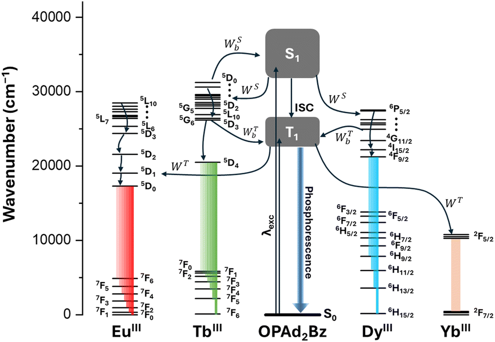 | ||
| Fig. 7 Schematic representation of the intramolecular energy transfer (IET) processes responsible for sensitization of the YbIII (1), TbIII (2), EuIII (5), and DyIII (4 and 7) ions via the OPAd2Bz ligand. The Jablonski-Perrin diagram illustrates the energy levels of the ligand's singlet (S1) and triplet (T1) excited states, as well as the relevant f–f transitions of the lanthanide ions. Energy transfer pathways include forward transfer via S1 (WS) and T1 (WT), as well as their corresponding backward processes (WSb and WTb). Intersystem crossing (ISC) and phosphorescence from the T1 state are also depicted due to their relevance in the photophysical processes. | ||
Conclusions
We report seven lanthanide complexes with two different geometries depending on the synthesis method, pentagonal bipyramidal (D5h) and octahedral (Oh), which contain YbIII (1), TbIII (2), GdIII (3 and 6), DyIII (4 and 7) and EuIII (5). In all of them, the di(1-adamantyl)benzylphosphine oxide ligand occupy axial positions, whereas chloride atoms and water molecules are located in the equatorial plane. Magnetic measurements carried out on compounds 1 and 2 reveal that complex 1 shows field-induced slow relaxation of the magnetisation and YbIII-centred NIR fluorescence, acting as a bifunctional compound. Ab initio calculations support the magnetic findings and provide further insights into the magnetic dynamics of the YbIII complex. They explain the presence of quantum tunnelling of magnetization (QTM) in the absence of a magnetic field and confirm that the relaxation process occurs primarily through Raman and direct relaxation pathways, rather than through the first excited doublet state.The photophysical properties of the coordination compounds and the OPAd2Bz ligand were investigated in detail through experimental studies and TD-DFT calculations, revealing that the ligand acts as an antenna for lanthanide emission across all compounds, with distinct intramolecular energy transfer (IET) pathways—via either S1 or T1 states—driving the sensitization depending on the specific complex, as confirmed by the calculated rates and resonance with important acceptor transitions. In addition, compounds 4, 5, and 7–8 present dual emission properties, which adds a piece to the rational design puzzle of dual emitters. Therefore, this study contributes to increasing the knowledge in the relaxation mechanism of the scarcely explored pentagonal bipyramidal YbIII-based field induced SIMs and provides further insight into the different mechanisms involved in lanthanide sensitization.
Author contributions
H. A. prepared the compounds and characterized them. A. R. E. performed all the quantum-chemical calculations and analyzed the results, apart from the IET rates analysis. J.-R. J. carried out the experimental photophysical characterization. A. N. C. N., R. T. M. Jr., and F. P. did the IET rates analysis, the M06-L/def2-SVP/MWB calculations, and wrote their corresponding section. A. N. was involved in conceptualisation, supervision and resources. M. A. P. analyzed the magnetic data. M. A. P. and M. M. Q.-M. wrote the original draft. E. C. conceived the idea, and reviewed/edited the manuscript. M. A. P., M. M. Q. M., E. C. acquired financial support and were involved in conceptualisation, supervision, validation, resources and project administration. All authors discussed the results and reviewed/edited the manuscript.Data availability
The authors confirm that the data supporting the findings of this study are available within the article and its ESI.†Conflicts of interest
There are no conflicts to declare.Acknowledgements
Financial support from Consejería de Universidad, Investigación e Innovación and ERDF Andalusia Program 2021-2027 (projects C-EXP-140-UGR23 and M.1.B.B TA_000722), Ministerio de Ciencia e Innovación (Project PID2022-138090NB-C21 funded by MCIN/AEI/10.13039/501100011033/FEDER,UE), Junta de Andalucía (FQM-195 and FQM-337), the University of Granada and University of Jaén is grateful acknowledged. The authors acknowledge the Centro de Servicios de Informática y Redes de Comunicaciones (CSIRC) for computational time and facilities. J. R. J. and M. M. Q. M. thank Ministerio de Ciencia e Innovación for their Ramón y Cajal contracts (RYC2022-037255-I and RYC2021-034288-I, respectively, funded both by MCIN/AEI/10.13039/501100011033 and by FSE+ and the European Union “NextGenerationEU”/PRTR”, respectively). RTMJr thanks the Brazilian National Council for Scientific and Technological Development – CNPq, Grant numbers 406483/2023-0, 310988/2023-3, and 404742/2024-6. F.P. acknowledge the Italian Ministry of University and Research for the received funds [PRIN (Progetti di Ricerca di Rilevante Interesse Nazionale, Bando 2022 PNRR) project “TheCURA”, Grant No. P20222TPZS].References
- Y. Yang, X. Hu, Z. Yang and W. Huang, Adv. Funct. Mater., 2025, 35, 2412970 CrossRef CAS.
- P. Li and H. Li, Coord. Chem. Rev., 2021, 441, 213988 CrossRef CAS.
- M. C. Heffern, L. M. Matosziuk and T. J. Meade, Chem. Rev., 2014, 114, 4496–4539 CrossRef CAS PubMed.
- J.-F. Lemonnier, L. Guénée, C. Beuchat, T. A. Wesolowski, P. Mukherjee, D. H. Waldeck, K. A. Gogick, S. Petoud and C. Piguet, J. Am. Chem. Soc., 2011, 133, 16219–16234 CrossRef CAS PubMed.
- A. Navarro, A. Ruiz-Arias, F. Fueyo-González, C. Izquierdo-García, T. Peña-Ruiz, M. Gutiérrez-Rodríguez, R. Herranz, J. M. Cuerva, J. A. González-Vera and A. Orte, Spectrochim. Acta, Part A, 2024, 323, 124926 CrossRef CAS PubMed.
- A. N. Carneiro Neto, E. E. S. Teotonio, G. F. de Sá, H. F. Brito, J. Legendziewicz, L. D. Carlos, M. C. F. C. Felinto, P. Gawryszewska, R. T. Moura Jr., R. L. Longo, W. M. Faustino and O. L. Malta, in Handbook on the Physics and Chemistry of Rare Earths, ed. J.-C. G. Bünzli and V. K. Pecharsky, Elsevier, 2019, vol. 56, pp. 55–162 Search PubMed.
- S. Torelli, D. Imbert, M. Cantuel, G. Bernardinelli, S. Delahaye, A. Hauser, J. C. G. Bünzli and C. Piguet, Chem. – Eur. J., 2005, 11, 3228–3242 CrossRef CAS PubMed.
- B. J. Crowston, J. D. Shipp, D. Chekulaev, L. K. McKenzie, C. Jones, J. A. Weinstein, A. J. H. Meijer, H. E. Bryant, L. Natrajan, A. Woodward and M. D. Ward, Dalton Trans., 2019, 48, 6132–6152 RSC.
- M. Poncet, C. Besnard, J.-R. Jiménez and C. Piguet, Inorg. Chem., 2024, 63, 18345–18354 CrossRef CAS PubMed.
- R. T. Moura, J. A. Oliveira, I. A. Santos, E. M. de Lima, L. D. Carlos, E. C. Aguiar and A. N. C. Neto, Adv. Theory Simul., 2021, 4, 2000304 CrossRef CAS.
- I. M. Alaoui, J. Phys. Chem., 1995, 99, 13280–13282 CrossRef CAS.
- E. Kasprzycka, V. A. Trush, V. M. Amirkhanov, L. Jerzykiewicz, O. L. Malta, J. Legendziewicz and P. Gawryszewska, Chem. – Eur. J., 2017, 23, 1318–1330 CrossRef CAS PubMed.
- E. Kasprzycka, A. N. Carneiro Neto, V. A. Trush, O. L. Malta, L. Jerzykiewicz, V. M. Amirkhanov, J. Legendziewicz and P. Gawryszewska, Spectrochim. Acta, Part A, 2022, 274, 121072 CrossRef CAS PubMed.
- R. Piñol, J. Zeler, C. D. S. Brites, Y. Gu, P. Téllez, A. N. Carneiro Neto, T. E. da Silva, R. Moreno-Loshuertos, P. Fernandez-Silva, A. I. Gallego, L. Martinez-Lostao, A. Martínez, L. D. Carlos and A. Millán, Nano Lett., 2020, 20, 6466–6472 CrossRef PubMed.
- J. Corredoira-Vázquez, C. González-Barreira, A. M. García-Deibe, J. Sanmartín-Matalobos, M. A. Hernández-Rodríguez, C. D. S. Brites, L. D. Carlos and M. Fondo, Inorg. Chem. Front., 2024, 11, 1087–1098 RSC.
- A. G. Bispo-Jr, L. Yeh, D. Errulat, D. A. Gálico, F. A. Sigoli and M. Murugesu, Chem. Commun., 2023, 59, 8723–8726 RSC.
- R. Marin, G. Brunet and M. Murugesu, Angew. Chem., Int. Ed., 2021, 60, 1728–1746 CrossRef CAS PubMed.
- R. Sessoli, D. Gatteschi, A. Caneschi and M. A. Novak, Nature, 1993, 365, 141–143 CrossRef CAS.
- S. M. J. Aubin, M. W. Wemple, D. M. Adams, H.-L. Tsai, G. Christou and D. N. Hendrickson, J. Am. Chem. Soc., 1996, 118, 7746–7754 CrossRef CAS.
- C. A. P. Goodwin, F. Ortu, D. Reta, N. F. Chilton and D. P. Mills, Nature, 2017, 548, 439–442 CrossRef CAS PubMed.
- A. Zabala-Lekuona, J. M. Seco and E. Colacio, Coord. Chem. Rev., 2021, 441, 213984 CrossRef CAS.
- D. N. Woodruff, R. E. P. Winpenny and R. A. Layfield, Chem. Rev., 2013, 113, 5110–5148 CrossRef CAS PubMed.
- R. Vincent, S. Klyatskaya, M. Ruben, W. Wernsdorfer and F. Balestro, Nature, 2012, 488, 357–360 CrossRef CAS PubMed.
- J. Long, Y. Guari, R. A. S. Ferreira, L. D. Carlos and J. Larionova, Coord. Chem. Rev., 2018, 363, 57–70 CrossRef CAS.
- E. Moreno-Pineda and W. Wernsdorfer, Nat. Rev. Phys., 2021, 3, 645–659 CrossRef CAS.
- A. M. Ako, I. J. Hewitt, V. Mereacre, R. Clérac, W. Wernsdorfer, C. E. Anson and A. K. Powell, Angew. Chem., Int. Ed., 2006, 45, 4926–4929 CrossRef CAS PubMed.
- N. Ishikawa, M. Sugita, T. Ishikawa, S. Koshihara and Y. Kaizu, J. Am. Chem. Soc., 2003, 125, 8694–8695 CrossRef CAS PubMed.
- J. Wang, Q. Li, S. Wu, Y. Chen, R. Wan, G. Huang, Y. Liu, J. Liu, D. Reta, M. J. Giansiracusa, Z. Wang, N. F. Chilton and M. Tong, Angew. Chem., Int. Ed., 2021, 60, 5299–5306 CrossRef CAS PubMed.
- C. A. Gould, K. R. McClain, D. Reta, J. G. C. Kragskow, D. A. Marchiori, E. Lachman, E.-S. Choi, J. G. Analytis, R. D. Britt, N. F. Chilton, B. G. Harvey and J. R. Long, Science, 2022, 375, 198–202 CrossRef CAS PubMed.
- F. Guo, B. M. Day, Y. Chen, M. Tong, A. Mansikkamäki and R. A. Layfield, Angew. Chem., Int. Ed., 2017, 56, 11445–11449 CrossRef CAS PubMed.
- J. Liu, Y. C. Chen, J. L. Liu, V. Vieru, L. Ungur, J. H. Jia, L. F. Chibotaru, Y. Lan, W. Wernsdorfer, S. Gao, X. M. Chen and M. L. Tong, J. Am. Chem. Soc., 2016, 138, 5441–5450 CrossRef CAS PubMed.
- S. Sakaue, A. Fuyuhiro, T. Fukuda and N. Ishikawa, Chem. Commun., 2012, 48, 5337 RSC.
- T. Morita, M. Damjanović, K. Katoh, Y. Kitagawa, N. Yasuda, Y. Lan, W. Wernsdorfer, B. K. Breedlove, M. Enders and M. Yamashita, J. Am. Chem. Soc., 2018, 140, 2995–3007 CrossRef CAS PubMed.
- Y. Chen, J. Liu, W. Wernsdorfer, D. Liu, L. F. Chibotaru, X. Chen and M. Tong, Angew. Chem., Int. Ed., 2017, 56, 4996–5000 CrossRef CAS PubMed.
- K. R. Meihaus and J. R. Long, J. Am. Chem. Soc., 2013, 135, 17952–17957 CrossRef CAS PubMed.
- M. A. AlDamen, J. M. Clemente-Juan, E. Coronado, C. Martí-Gastaldo and A. Gaita-Ariño, J. Am. Chem. Soc., 2008, 130, 8874–8875 CrossRef CAS PubMed.
- F.-S. Guo, B. M. Day, Y.-C. Chen, M.-L. Tong, A. Mansikkamäki and R. A. Layfield, Science, 2018, 362, 1400–1403 CrossRef CAS PubMed.
- J.-P. Sutter, V. Béreau, V. Jubault, K. Bretosh, C. Pichon and C. Duhayon, Chem. Soc. Rev., 2022, 51, 3280–3313 RSC.
- Y. Ding, N. F. Chilton, R. E. P. Winpenny and Y. Zheng, Angew. Chem., Int. Ed., 2016, 55, 16071–16074 CrossRef CAS PubMed.
- Y. Ding, T. Han, Y. Zhai, D. Reta, N. F. Chilton, R. E. P. Winpenny and Y. Zheng, Chem. – Eur. J., 2020, 26, 5893–5902 CrossRef CAS PubMed.
- K.-X. Yu, J. G. C. Kragskow, Y.-S. Ding, Y.-Q. Zhai, D. Reta, N. F. Chilton and Y.-Z. Zheng, Chem, 2020, 6, 1777–1793 CAS.
- Y.-S. Ding, K.-X. Yu, D. Reta, F. Ortu, R. E. P. Winpenny, Y.-Z. Zheng and N. F. Chilton, Nat. Commun., 2018, 9, 3134 CrossRef PubMed.
- Z. Jiang, L. Sun, Q. Yang, B. Yin, H. Ke, J. Han, Q. Wei, G. Xie and S. Chen, J. Mater. Chem. C, 2018, 6, 4273–4280 RSC.
- L. Zhu, Y. Dong, B. Yin, P. Ma and D. Li, Dalton Trans., 2021, 50, 12607–12618 RSC.
- M. S. Raju, K. Paillot, I. Breslavetz, G. Novitchi, G. L. J. A. Rikken, C. Train and M. Atzori, J. Am. Chem. Soc., 2024, 146, 23616–23624 CrossRef CAS PubMed.
- J. P. Costes, S. Titos-Padilla, I. Oyarzabal, T. Gupta, C. Duhayon, G. Rajaraman and E. Colacio, Inorg. Chem., 2016, 55, 4428–4440 CrossRef CAS PubMed.
- J. Larionova, Y. Guari, S. Sene and G. Félix, in Handbook on the Physics and Chemistry of Rare Earths, ed. J. G. Bünzli and S. M. Kauzlarich, Elsevier, 2023, vol. 64, pp. 93–173 Search PubMed.
- J.-T. Chen, T.-D. Zhou and W.-B. Sun, Dalton Trans., 2023, 52, 4643–4657 RSC.
- Y. Bi, C. Chen, Y.-F. Zhao, Y.-Q. Zhang, S.-D. Jiang, B.-W. Wang, J.-B. Han, J.-L. Sun, Z.-Q. Bian, Z.-M. Wang and S. Gao, Chem. Sci., 2016, 7, 5020–5031 RSC.
- M. Fondo, J. Corredoira-Vázquez, A. M. García-Deibe, J. Sanmartín-Matalobos, M. Amoza, A. M. P. Botas, R. A. S. Ferreira, L. D. Carlos and E. Colacio, Inorg. Chem. Front., 2020, 7, 3019–3029 RSC.
- G. Cucinotta, M. Perfetti, J. Luzon, M. Etienne, P. Car, A. Caneschi, G. Calvez, K. Bernot and R. Sessoli, Angew. Chem., Int. Ed., 2012, 51, 1606–1610 CrossRef CAS PubMed.
- Y. Gil, M. M. Quesada-Moreno, M. A. Palacios, S. Gómez-Coca, E. Colacio, E. Ruiz and D. Aravena, Inorg. Chem. Front., 2025, 12, 2856–2871 RSC.
- H. Allia, A. García-Camacho, M. Á. Palacios, D. Aravena, M. M. Quesada-Moreno and E. Colacio, in preparation.
- Bruker, APEX2, SAINT and SADABS, Madison, Wisconsin, USA, 2012 Search PubMed.
- Bruker AXS, Version 8.40b, Madison, WI, 2016 Search PubMed.
- G. M. Sheldrick, Version 2016/2, 2016 Search PubMed.
- G. M. Sheldrick, Acta Crystallogr., Sect. A: Found. Adv., 2015, 71, 3–8 CrossRef PubMed.
- G. M. Sheldrick, Acta Crystallogr., Sect. C: Struct. Chem., 2015, 71, 3–8 CrossRef PubMed.
- O. V. Dolomanov, L. J. Bourhis, R. J. Gildea, J. A. K. Howard and H. Puschmann, J. Appl. Crystallogr., 2009, 42, 339–341 CrossRef CAS.
- M. J. Frisch, G. W. Trucks, H. B. Schlegel, G. E. Scuseria, M. A. Robb, J. R. Cheeseman, G. Scalmani, V. Barone, G. A. Petersson, H. Nakatsuji, X. Li, M. Caricato, A. V. Marenich, J. Bloino, B. G. Janesko, R. Gomperts, B. Mennucci, H. P. Hratchian, J. V. Ortiz, A. F. Izmaylov, J. L. Sonnenberg, D. Williams-Young, F. Ding, F. Lipparini, F. Egidi, J. Goings, B. Peng, A. Petrone, T. Henderson, D. Ranasinghe, V. G. Zakrzewski, J. Gao, N. Rega, G. Zheng, W. Liang, M. Hada, M. Ehara, K. Toyota, R. Fukuda, J. Hasegawa, M. Ishida, T. Nakajima, Y. Honda, O. Kitao, H. Nakai, T. Vreven, K. Throssell, J. A. J. Montgomery, J. E. Peralta, F. Ogliaro, M. J. Bearpark, J. J. Heyd, E. N. Brothers, K. N. Kudin, V. N. Staroverov, T. A. Keith, R. Kobayashi, J. Normand, K. Raghavachari, A. P. Rendell, J. C. Burant, S. S. Iyengar, J. Tomasi, M. Cossi, J. M. Millam, M. Klene, C. Adamo, R. Cammi, J. W. Ochterski, R. L. Martin, K. Morokuma, O. Farkas, J. B. Foresman and D. J. Fox, 2016.
- Y. Zhao and D. G. Truhlar, Theor. Chem. Acc., 2008, 120, 215–241 Search PubMed.
- A. Schäfer, H. Horn and R. Ahlrichs, J. Chem. Phys., 1992, 97, 2571–2577 CrossRef.
- M. Dolg, H. Stoll and H. Preuss, J. Chem. Phys., 1989, 90, 1730–1734 CrossRef CAS.
- L. Blois, R. T. Moura, R. L. Longo, O. L. Malta, H. F. Brito and A. N. Carneiro Neto, J. Comput. Chem., 2025, 46, e70034 CrossRef CAS PubMed.
- R. T. Moura, M. Quintano, C. V. Santos-Jr, V. A. C. A. Albuquerque, E. C. Aguiar, E. Kraka and A. N. Carneiro Neto, Opt. Mater. X, 2022, 16, 100216 CAS.
- A. N. Carneiro Neto, J. Nasalska, P. Gawryszewska, V. A. Trush, J. Sokolnicki, O. L. Malta and J. Legendziewicz, Spectrochim. Acta, Part A, 2025, 324, 124875 CrossRef CAS PubMed.
- A. N. Carneiro Neto, R. T. Moura, L. D. Carlos, O. L. Malta, M. Sanadar, A. Melchior, E. Kraka, S. Ruggieri, M. Bettinelli and F. Piccinelli, Inorg. Chem., 2022, 61, 16333–16346 CrossRef CAS PubMed.
- A. N. Carneiro Neto and R. T. Moura, Chem. Phys. Lett., 2020, 757, 137884 CrossRef CAS.
- S. Edvardsson and M. Klintenberg, J. Alloys Compd., 1998, 275–277, 230–233 CrossRef CAS.
- B. R. Judd, Operator Techniques in Atomic Spectroscopy, McGraw-Hill Book Company, New York, 1998 Search PubMed.
- W. T. Carnall, H. Crosswhite and H. M. Crosswhite, Energy level structure and transition probabilities in the spectra of the trivalent lanthanides in LaF3, Argonne, IL, United States, 1978 Search PubMed.
- T. Kushida, J. Phys. Soc. Jpn., 1973, 34, 1318–1326 CrossRef CAS.
- E. Kasprzycka, A. N. Carneiro Neto, V. A. Trush, L. Jerzykiewicz, V. M. Amirkhanov, O. L. Malta, J. Legendziewicz and P. Gawryszewska, J. Rare Earths, 2020, 38, 552–563 CrossRef CAS.
- O. L. Malta and F. R. Gonçalves e Silva, Spectrochim. Acta, Part A, 1998, 54, 1593–1599 CrossRef.
- R. T. Moura Jr., A. N. Carneiro Neto, E. C. Aguiar, C. V. Santos-Jr, E. M. de Lima, W. M. Faustino, E. E. S. Teotonio, H. F. Brito, M. C. F. C. Felinto, R. A. S. Ferreira, L. D. Carlos, R. L. Longo and O. L. Malta, Opt. Mater. X, 2021, 11, 100080 CAS.
- F. Neese, 2012, 2, 73–78.
- F. Neese, F. Wennmohs, U. Becker and C. Riplinger, J. Chem. Phys., 2020, 152, 224108 CrossRef CAS PubMed.
- F. Neese, Wiley Interdiscip. Rev.: Comput. Mol. Sci., 2022, 12, 1–15 Search PubMed.
- P.-Å. Malmqvist and B. O. Roos, Chem. Phys. Lett., 1989, 155, 189–194 CrossRef CAS.
- A. Abhervé, M. Mastropasqua Talamo, N. Vanthuyne, F. Zinna, L. Di Bari, M. Grasser, B. Le Guennic and N. Avarvari, Eur. J. Inorg. Chem., 2022, e202200010 CrossRef.
- D. Ganyushin and F. Neese, J. Chem. Phys., 2013, 138, 104113 CrossRef PubMed.
- D. Ganyushin and F. Neese, J. Chem. Phys., 2006, 125, 024103 CrossRef PubMed.
- R. Maurice, R. Bastardis, C. de Graaf, N. Suaud, T. Mallah and N. Guihéry, J. Chem. Theory Comput., 2009, 5, 2977–2984 CrossRef CAS PubMed.
- F. Neese, J. Chem. Phys., 2005, 122, 034107 CrossRef PubMed.
- M. Douglas and N. M. Kroll, Ann. Phys., 1974, 82, 89–155 CAS.
- T. Nakajima and K. Hirao, Chem. Rev., 2012, 112, 385–402 CrossRef CAS PubMed.
- F. Weigend and R. Ahlrichs, Phys. Chem. Chem. Phys., 2005, 7, 3297 RSC.
- A. Schäfer, C. Huber and R. Ahlrichs, J. Chem. Phys., 1994, 100, 5829–5835 CrossRef.
- D. Aravena, F. Neese and D. A. Pantazis, J. Chem. Theory Comput., 2016, 12, 1148–1156 CrossRef CAS PubMed.
- L. F. Chibotaru and L. Ungur, J. Chem. Phys., 2012, 137, 064112 CrossRef CAS PubMed.
- L. Ungur and L. F. Chibotaru, Inorg. Chem., 2016, 55, 10043–10056 CrossRef CAS PubMed.
- M. Llunell, D. Casanova, J. Cirera, P. Alemany and S. Alvarez, SHAPE v2.1, Continuous Shape Measures Calculation, Electronic Structure Group, Universitat de Barcelona, contact: llunell@ub.edu, 2013 Search PubMed.
- A. V. Gavrikov, N. N. Efimov, Z. V. Dobrokhotova, A. B. Ilyukhin, P. N. Vasilyev and V. M. Novotortsev, Dalton Trans., 2017, 46, 11806–11816 RSC.
- J. Ruiz, G. Lorusso, M. Evangelisti, E. K. Brechin, S. J. A. Pope and E. Colacio, Inorg. Chem., 2014, 53, 3586–3594 CrossRef CAS PubMed.
- J.-L. Liu, K. Yuan, J.-D. Leng, L. Ungur, W. Wernsdorfer, F.-S. Guo, L. F. Chibotaru and M.-L. Tong, Inorg. Chem., 2012, 51, 8538–8544 CrossRef CAS PubMed.
- F. Guégan, J. Jung, B. Le Guennic, F. Riobé, O. Maury, B. Gillon, J.-F. Jacquot, Y. Guyot, C. Morell and D. Luneau, Inorg. Chem. Front., 2019, 6, 3152–3157 RSC.
- A. Singh and K. N. Shrivastava, Phys. Status Solidi, 1979, 95, 273–277 CrossRef CAS.
- K. N. Shrivastava, Phys. Status Solidi, 1983, 117, 437–458 CrossRef CAS.
- A. Borah, S. Dey, S. K. Gupta, M. G. Walawalkar, G. Rajaraman and R. Murugavel, Chem. Commun., 2020, 56, 11879–11882 RSC.
- A. Borah, S. Dey, K. Siddiqui, S. K. Gupta, G. Rajaraman and R. Murugavel, Dalton Trans., 2024, 53, 7263–7267 RSC.
- R. B. Cundall, D. A. Robinson and L. C. Pereira, in Advances in Photochemistry, ed. N. Pitts Jr., G. S. Hammond and K. Gollnick, John Wiley & Sons, Inc., New York, 1977, vol. 10, pp. 147–219 Search PubMed.
- J. Mooney and P. Kambhampati, J. Phys. Chem. Lett., 2013, 4, 3316–3318 CrossRef CAS.
- Y. Ma, M. Zhu, Y. Zhang, E. Gao and S. Wu, Inorg. Chim. Acta, 2022, 537, 120928 CrossRef CAS.
- K. Yuhara, K. Tanaka and Y. Chujo, Mater. Chem. Front., 2022, 6, 1414–1420 RSC.
- L. E. do, N. Aquino, G. A. Barbosa, J. de, L. Ramos, S. O. K. Giese, F. S. Santana, D. L. Hughes, G. G. Nunes, L. Fu, M. Fang, G. Poneti, A. N. Carneiro Neto, R. T. Moura, R. A. S. Ferreira, L. D. Carlos, A. G. Macedo and J. F. Soares, Inorg. Chem., 2021, 60, 892–907 CrossRef PubMed.
- A. N. Carneiro Neto, E. Kasprzycka, A. S. Souza, P. Gawryszewska, M. Suta, L. D. Carlos and O. L. Malta, J. Lumin., 2022, 248, 118933 CrossRef CAS.
- A. G. Bispo-Jr, I. O. Mazali and F. A. Sigoli, Phys. Chem. Chem. Phys., 2022, 24, 13565–13570 RSC.
- B. Ay, R. Takano and T. Ishida, Solid State Sci., 2024, 157, 107723 CrossRef CAS.
- X. Liu, R. Yang, L. Zhang, J. Zhou, C. Huang, H. Zou and Z. Xiao, J. Rare Earths, 2024, 42, 1101–1109 CrossRef CAS.
- L. N. Puntus, D. A. Bardonov, E. A. Varaksina, I. V. Taydakov, D. M. Roitershtein, I. E. Nifant’ev and K. A. Lyssenko, Mendeleev Commun., 2024, 34, 325–328 CrossRef CAS.
- N. M. Moraes Fernandes, G. Barbosa-Reis, D. Oliveira-Silva and I. A. Bagatin, ChemistrySelect, 2023, 8, e202302321 CrossRef CAS.
- D. M. Lyubov, T. V. Mahrova, A. V. Cherkasov, G. K. Fukin, Y. V. Fedorov and A. A. Trifonov, Eur. J. Inorg. Chem., 2023, e202300292 CrossRef CAS.
- Sushila, R. Siddiqui, S. Patra, K. Shivam, A. Sil, B. Guchhait, H. Tian, R. Kataria, S. Goswami, P. Venugopalan and R. Patra, Inorg. Chem., 2022, 61, 11484–11496 CrossRef CAS PubMed.
- L. S. Natrajan, A. J. Blake, C. Wilson, J. A. Weinstein and P. L. Arnold, Dalton Trans., 2004, 3748 RSC.
Footnote |
| † Electronic supplementary information (ESI) available. CCDC 2411638–2411642. For ESI and crystallographic data in CIF or other electronic format see DOI: https://doi.org/10.1039/d4cp04862h |
| This journal is © the Owner Societies 2025 |