
 Open Access Article
 This Open Access Article is licensed under a Creative Commons Attribution-Non Commercial 3.0 Unported Licence
A molecular dynamics simulation study on hydrocarbon ladder polymer membranes for gas separation†
Wenxuan
Tian
a,
Lidong
Gong
 *a,
Chunyang
Yu
*bc and
Yongfeng
Zhou
bc
*a,
Chunyang
Yu
*bc and
Yongfeng
Zhou
bc
aSchool of Chemistry & Chemical Engineering, Liaoning Normal University, 850 Huanghe Road, Dalian, 116029, China. E-mail: gongjw@lnnu.edu.cn
bSchool of Chemistry & Chemical Engineering, Frontiers Science Center for Transformative Molecules, Shanghai Key Laboratory of Electrical Insulation and Thermal Aging, Shanghai Jiao Tong University, 800 Dongchuan Road, Shanghai, 200240, China. E-mail: chunyangyu@sjtu.edu.cn
cKey Laboratory of Green and High-end Utilization of Salt Lake Resources, Chinese Academy of Sciences, China
First published on 21st February 2025
Abstract
To address global environmental challenges and support the transition of energy systems, the study of CO2 capture and separation is at the forefront of scientific research. Utilizing membranes based on polymers of intrinsic microporosity (PIMs) for CO2 separation presents a promising approach. However, the mechanisms of CO2 separation in PIMs are not fully understood. In this study, an isobaric model combined with molecular dynamics (MD) simulation was used to explore the adsorptive and diffusive behaviors of CO2 and N2 in PIM membranes. We elucidated the gas separation mechanism by analyzing three critical aspects: microporous structure, adsorptive selectivity, and diffusive selectivity. The findings reveal that PIM membranes exhibit advantageous separation characteristics due to their large Brunauer–Emmett–Teller (BET) surface areas and Pore Limiting Diameters (PLDs) that are more compatible with the size of CO2 molecules. Additionally, the difference in solvation free energy and diffusion rates between the two gases within the membranes significantly contributes to their selectivity. Specifically, CO2 diffuses within the membrane primarily through a hopping mechanism supplemented by diffusive motion, whereas N2 relies mainly on diffusion with less hopping. Since dissolution often takes precedence over diffusion in the separation process, it can sometimes lead to less effective diffusion for gas molecules. Moreover, the simulation results indicate that the diffusion behavior of the CO2/N2 mixture in PIM membranes is governed by a solubility-driven separation mechanism. This work provides a theoretical foundation for understanding gas transport and separation mechanisms in PIM membranes.
1 Introduction
As industrial activities have intensified, the increase in CO2 emissions has brought numerous environmental challenges, including a rise in global temperatures and strengthening of the greenhouse effect.1 Notably, this includes sea level rise2 and ocean acidification.3 Capturing and storing carbon dioxide from industrial and power generation processes can significantly reduce greenhouse gas emissions in the atmosphere, thereby helping to limit the rise in global average temperatures. For many countries, the separation and capture of CO2 represent a crucial technological approach to achieving the greenhouse gas emission reduction targets stipulated by the Paris Agreement.Polymer membrane separation is regarded as an effective method for CO2 separation. Among all polymer materials, PIMs stand out due to their unique microporous structures. The rigid and contorted skeletons of PIMs hinder chain packing in the solid state, creating significant free volume. These features endow PIMs with superior separation properties compared to traditional polymers,4–6 particularly for separating CO2 from other gases such as N2, H2, or CH4.
Due to their outstanding performance, PIMs have established the upper bounds for nearly all gas separations,7,8 making them a focal point of research in recent years. Since the development of the original PIM-1 prototype, numerous PIMs and their derivatives have been created.9,10 However, a significant limitation of membrane-based gas separations is the well-known trade-off between permeability and selectivity, which results in performance upper bounds.11 Despite promising advancements, designing highly selective PIMs remains a challenge. Yong et al.12 were the first to report on the gas separation performance of CO2/CH4 using mixed matrix membranes composed of PIM-1 and Matrimid. Since then, PIM-1 has been modified through various techniques aimed at increasing the pore volume and enhancing gas selectivity. These modifications include cyano group post-treatment (such as conversion to carboxylic groups,13,14 sulfonamides,15 tetrazoles,16,17 or amidoxime18), cross-linking,19–21 copolymerization,22 development of mixed matrix membranes,23–28 and the design of specific monomer units.29–32 Rodriguez et al.33 reported that at 2 atm, amine-functionalized PIM-1 (PIM-NH2) showed a significant increase in selectivity for CO2/N2 mixtures compared to pure gases. Recent research by Lai et al.34 introduced a novel class of carbon-hydrogen ladder polymers that offer both higher selectivity and greater permeability than other membranes in the separation of various industrially relevant gas mixtures while maintaining desirable mechanical and thermal properties in the corresponding films. Unlike traditional PIM membranes, these new polymers opt for more rigid, less flexible bridged-ring structures over highly flexible spirocyclic ones (Fig. 1a). Such PIM membranes promise a combination of mechanical robustness and superior separation efficiency. Experimental conjectures suggest that different hydrocarbon ladder configurations significantly affect chain arrangement and the distribution and connectivity of free volume. Although gas adsorption isotherms and X-ray scattering experiments are commonly used to characterize the porosity of microporous materials, these techniques struggle to capture interactions and relationships at the molecular or atomic level, which are crucial for overcoming separation diffusion bottlenecks. Therefore, employing molecular simulation techniques to reveal the gas separation mechanism of PIM membranes is essential for designing new types of membranes.
 | ||
| Fig. 1 (a) Bridged-ring structure of the DHP monomer and Me2F monomer; (b) spiro-linkage structure of the PIM-1 monomer. | ||
Molecular simulation is a powerful tool for studying adsorptive materials, offering insights into ideal systems and conditions that are experimentally unattainable. For instance, Fang et al.35 conducted simulations on gas permeation through membranes made of intrinsic microporous polymers (PIM-1 and PIM-7). They discovered that nitrile groups in the polymers’ base structure enhanced affinity and increased the fractional free volume (FFV), outperforming most glassy polymer membranes in adsorption and diffusion. Hart et al.36 integrated sulphur into the monomeric framework, offering an additional site, thereby significantly enhancing CO2 adsorption isotherms and isosteric heat of adsorption in PIMs. Liu et al.37 used molecular dynamics simulations to assess the separation performance of PILP-1 and PILP-3 for CO2/CH4 mixtures under constant pressure gradients. This work highlighted the significance of polymer flexibility and membrane plasticization in gas permeation, emphasizing the critical role of gas sorption in CO2/CH4 separation. Xu et al.38 examined organic solvent nanofiltration across six PIMs, including the original PIM-1 and five functionalized variants, finding a strong correlation between solvent permeability and the interaction between membrane and solvent properties. These simulation studies offer valuable insights into separation processes in polymer films with intrinsic micropores under specific chemical conditions.
In our study, inspired by previous research, we employed classical molecular dynamics (MD) simulations to explore the gas separation mechanisms of a novel type of hydrocarbon ladder polymer.34 Herein, two types of PIM membranes (Me2F and DHP) were selected as model candidates. Their preparation process is as follows: ladder dinorbornenes were synthesized from 2,7-dibromofluorene derivatives that reacted with excess norbornadiene in the presence of a palladium catalyst; these intermediates subsequently underwent efficient and clean CANAL polymerization with p-dibromo–p-xylene to form ladder polymers Me2F and DHP.34 The structures of Me2F and DHP are shown in Fig. 1a. Unlike classical PIM-1 materials (Fig. 1b), Me2F and DHP feature rigid bridged-ring structures rather than spiro-linkages, limiting the degrees of freedom in polymer chains and inhibiting polymer chain packing. This structural difference provides more accessible channels for gas permeation.
Based on the simulation results, we directly observed the channels and pore structures formed by the rigid stacking of the polymer. We measured the size and distribution of the pores within the membranes as well as the Brunauer–Emmett–Teller (BET) surface area. The entire separation process was analyzed by dividing it into solubility-driven and diffusion-driven components, and we examined the degree of gas dissolution in different membranes through free energy calculations. The kinetic mechanism of gas molecule permeation was investigated using the van Hove function and density functional theory (DFT) calculations. This work provides a foundation for understanding gas separation in these types of membranes and serves as a reference for designing high-performance PIM membranes.
2 Model construction and simulation details
2.1 Model construction
The single polymer chain, comprising 20 monomers of Me2F and DHP, is terminated with hydrogen atoms. Owing to the distinctive rigidity of the new class of carbon–hydrogen ladder PIMs, initial structures were created within a large simulation box, resulting in a polymer system of low density. The insert-molecules module from the Gromacs package39 was utilized to embed 40 polymer chains into the initial simulation box, with dimensions of x = 100 nm, y = 100 nm, and z = 100 nm, as illustrated in Fig. 2a. At present, there is a lack of experimental data regarding the density of Me2F and DHP membranes. In this study, a compression/relaxation strategy consisting of 21 steps was implemented, following the methodology outlined by Colina et al.40 It was observed that employing a 21-step gradual decompression scheme ensures that the final simulation density remains unaffected by the maximum pressure applied. The gradual decompression process, involving a maximum temperature of 600 K and a maximum pressure of 50![[thin space (1/6-em)]](https://www.rsc.org/images/entities/char_2009.gif) 000 bar, cyclically anneals the system to produce a realistic polymer configuration. This technique has been successfully employed in compressing several PIM membranes. Adhering to the 21-step MD compression and relaxation protocol, the current simulation system was compressed to the target density, resulting in a final box size of x = y = z = 8.9 nm, as depicted in Fig. 2b.
000 bar, cyclically anneals the system to produce a realistic polymer configuration. This technique has been successfully employed in compressing several PIM membranes. Adhering to the 21-step MD compression and relaxation protocol, the current simulation system was compressed to the target density, resulting in a final box size of x = y = z = 8.9 nm, as depicted in Fig. 2b.
 | ||
| Fig. 2 (a) The initial low-density simulation box; (b) the simulation box after 21-step MD compression; (c) the gas diffusion model of membranes with a constant concentration gradient. | ||
To construct the gas separation system, the post-annealing and compression states were adopted as the initial configuration for developing the CO2/N2 mixed gas separation model, resulting in the final separation system as illustrated in Fig. 2c. The simulation box dimensions were set as x = 8.9 nm, y = 8.9 nm, and z = 100 nm. The simulation system was divided into three distinct regions: the left side representing the packing zone, the middle region as the dissolution and permeation zone, and the right side serving as the separation zone.41 To maintain the volume of the left packing zone constant and prevent the displacement of the polymer film during simulation, a positional constraint was applied to the layer of atoms with the highest Z-coordinate in the PIM membrane.42 In Fig. 2c, the purple atoms in the dissolution and permeation zone depict the atoms constrained throughout the simulation process. The volume of the separation zone was slightly larger than that of the packing zone to ensure a lower gas density in the separation zone. To prevent gas molecules from crossing between the packing and separation zones, identical-sized graphene sheets were placed on the left and right sides along the XY-plane. The carbon atoms in the graphene were assigned the charge of zero during the simulation, and uniform interactions between the graphene sheet, membrane, and gas molecules on both sides were maintained. Additionally, a vacuum region was introduced on either side of the graphene sheets to prevent interference between the two graphene layers.38
In the initial phase of the simulation, the system is equilibrated for 100 ns. During the first 50 ns, 100 molecules each of CO2 and N2 are introduced to the packing zone, initiating the dissolution of gas molecules into the membrane driven by a concentration gradient. Subsequently, in the following 50 ns, the gas molecules in the separation zone are removed, and new CO2 and N2 molecules are inserted into the packing zone to maintain the original number of gas molecules. Following this setup, the balanced system undergoes a 240 ns NVT production process to investigate the separation and diffusion mechanisms of gas molecules within hydrocarbon ladder polymer membranes. The simulation temperature was set as 308 K for this process. This production phase sheds light on the gas separation process and the behaviours of the polymer membrane in gas separation applications.
2.2 Simulation details
In the previous work by Kyle et al.,43 the generalized AMBER force field (GAFF) was employed to model rigid, amorphous, and glassy polymer materials. Their findings indicated that the GAFF could effectively capture crucial details such as pore topology and adsorption capacity. Building on their research, PIMs are also modelled using the GAFF,44 while small gas molecules are described with the transferable potential for phase equilibria-united atom (TraPPE-UA) force field.45–48 For the nonbonded interactions, the Lorentz–Berthelot combination rules for the cross Lennard–Jones (LJ) parameter were adopted. The LJ parameters and atomic information for all gas atoms are provided in Tables S1–S3 (ESI†).In the simulation process, CO2 and N2 molecules were modelled as linear molecules, with virtual atoms introduced to allocate the mass and charge appropriately across the molecules. This approach ensured that the gas molecules had accurate charge distributions within the molecular model. All molecular dynamics simulations were conducted using GROMACS-2021.6-GPU.49 The Nosé–Hoover thermostat was utilized to maintain constant temperature, while the Parrinello–Rahman barostat controlled the pressure.50 The long-range electrostatic interactions were calculated using the particle-mesh Ewald (PME) method. A cutoff distance of 1.5 nm was used for the LJ potential. The time step for all simulations was set as 1 fs. The final configurations of different systems were visualized by using VMD (version 1.9.3)51 software.
As the simulation progressed, it was observed that the number of gas molecules in the separation zone increased, leading to a decreased concentration gradient and a reduction in the rate of permeation. To address this issue, a constant concentration differential was maintained throughout the separation and diffusion processes. At regular intervals, denoted by τ, the quantities of gas molecules in both the feed and separation zones were assessed. Gas molecules in the packing zone were replenished according to the initial CO2 to N2 ratio (CO2 = 100, N2 = 100, and CO2:N2 = 1:1). Simultaneously, gas molecules that had permeated into the separation zone were removed. This procedure ensured that the number of CO2 and N2 molecules remained constant at 100 in the packing zone, while the separation zone was reset to zero. The original molecular forces and velocities were conserved during the replenishment and extraction processes. Newly added gas molecules underwent a brief dynamic equilibration to adapt to the system conditions. Liu and co-workers42 have emphasized the importance of maintaining a constant pressure differential in MD simulations. Their findings suggested that τ values ranging from 150 to 250 ps resulted in stable adsorption levels of CO2 by using the PIM membrane, without significant fluctuations. To ensure a constant pressure difference between the packing and separation zone, the number of molecules adsorbed by the membrane across different τ values was verified. The results indicated minimal changes in the number of adsorbed gas molecules under varying τ values, as illustrated in Fig. S3 (ESI†). Consequently, the τ interval for gas addition and removal was set at 200 ps in this study.
2.3 Quantum chemistry calculation
To quantitatively investigate the interactions of gas molecules and further explore the distributions of CO2 and N2 in hydrocarbon ladder polymers, three interaction models were constructed, which are CO2–CO2, N2–N2, and CO2–N2, respectively. Then, the geometries of all molecules were optimized using density functional theory (DFT) at the GB3LYP-D3/6-31G** level of theory. All calculations are performed using BDF software on the Device Studio platform.51–56 The interaction region indicator (IRI)57 analysis was performed through the Multiwfn (version 3.8_dev) software package.583 Results and discussion
3.1 Structure and properties of membranes
Molecular simulations offer a unique advantage by providing the atomistic details of the polymeric structure and pore topology.59 The model construction scheme involved a deliberate compression over 21 steps, culminating in an 800 ps NPT simulation that provided the converged density of Me2F and DHP polymers at 835.52 kg m−3 and 874.21 kg m−3, respectively. The equilibrium densities of Me2F and DHP are depicted in Fig. S1 (ESI†).PIMs are a class of porous glassy polymers known for their substantial free volume, a key structural feature that contributes to their high gas permeability.16,60 Understanding the pore parameters of these materials is crucial for comprehending their structure and functionality. To evaluate these parameters, Zeo++ software was employed to analyse the pore size metrics of the polymer membrane.61 This analysis enabled the calculation of several important properties,62 including the fractional free volume (FFV), global cavity diameter (GCD), pore limiting diameter (PLD), largest cavity diameter (LCD), BET surface area, and pore size distribution (PSD),63 among others. Table 1 presents detailed BET and FFV data for the membrane, while Fig. 3a and b depict the structure of the membrane's channels and cavities. The entire channel system was divided into two parts: the channel part and the cavity part. Fig. S2 (ESI†) provides a visual representation of the GCD, PLD, and LCD. This comprehensive characterization provides essential insights into the structural attributes of PIMs, which are critical for optimizing their performance in gas separation applications.
| Mem | GCD (Å) | PLD (Å) | LCD (Å) | FFV (%) | BET surface area (m2 g−1) (our work) | BET surface area (m2 g−1) (experiment)34 |
|---|---|---|---|---|---|---|
| DHP | 11.83 (±1.74) | 4.56 (±0.20) | 10.28 (±1.24) | 53.64 | 1230.35 (±31.29) | 870 |
| Me2F | 13.35 (±2.33) | 4.12 (±0.17) | 11.53 (±1.19) | 55.47 | 1636.96 (±15.34) | 1190 |
 | ||
| Fig. 3 The chain distribution and FFV of (a) DHP and (b) Me2F membranes; (c) the pore-size distribution of Me2F and DHP membranes. | ||
In experiments, hydrocarbon ladder polymer membranes are utilized not only for the separation of CO2 and N2 but also for other gases such as CH4 and H2. To study the pore characteristics, H2 (with a kinetic radius of 0.14 nm) was selected as a probe molecule. Upon the removal of polymer membranes from all gas molecules, specific information about pore size and surface area can be obtained. The pore size distribution of the Me2F and DHP membranes is shown in Fig. 3c. The minimum pore size of the membranes is approximately 2–3 Å, with the maximum size around 10 Å, and an average size distribution of about 5–6 Å. The distribution indicates that the predominant pore sizes in the Me2F membrane are slightly larger than those in the DHP membrane, which aligns with the observed density distribution. The kinetic diameters of CO2 and N2 are 3.47 Å and 3.58 Å, respectively,64 making them comparable to the pore sizes in both PIM membranes. This similarity facilitates effective permeation of gases like CO2 and N2. It is generally believed that pores with diameters less than 3 Å will be ineffective for gas diffusion, leading to inaccessible areas within the polymer membrane, whereas pores around 10 Å may lack the necessary screening performance. Thus, PIM membranes are expected to be highly effective in separating CO2 and N2. Additionally, as seen in Table 1, aside from the pore limiting diameter (PLD), most metrics indicate that the pore sizes in Me2F are slightly larger than those in DHP, which may correlate with the superior permeability observed in Me2F. This finding is consistent with conclusions derived from experimental data (Table S2, ESI†).34 It should be noted that the calculated surface area is greater than the experimental values, potentially due to differences between simulation calculations and experimental measurements.65 Furthermore, Me2F has a larger BET surface area compared to DHP, suggesting that gas molecules are more apt to interact with Me2F.
3.2 Absorption behaviours of the CO2/N2 mixture in membranes
To explore the gas transport mechanism in a more intuitive manner, we divided the entire separation process into two steps: adsorption and diffusion. Fig. 4a displays the adsorption quantities of CO2/N2 mixtures during the permeation process in two distinct membranes. We defined gas molecules as sorbed in the membrane if they were within 0.54 nm of the membrane atoms.42 In Fig. 4a, the adsorption of CO2 is observed to rapidly increase within the initial 10 ns, which subsequently rises gradually from 20 ns to 50 ns, and ultimately stabilizes after 50 ns. This trend suggests that in the initial phase, PIM membranes adsorb CO2 rapidly. As the adsorption amount increases, the pores of the polymer membrane were occupied progressively by CO2 molecules, after which the adsorption rate decreases gradually and approaches stability, eventually fluctuating around a specific value. In contrast, the adsorbed quantity of N2 molecules was significantly lower throughout the entire adsorption process and nearly a constant during the simulation period. We can find that the adsorption quantity of CO2 is obviously greater than that of N2. | ||
| Fig. 4 (a) The variations of the adsorption number of CO2 and N2 molecules versus simulation time; (b) the variation of the membrane density versus simulation time; solvation free energies of two gas molecules in (c) DHP and (d) Me2F membranes. | ||
This disparity in adsorption quantities indicates that CO2 has a much stronger affinity for the membrane than N2. This can be attributed to the molecular interactions and the more fitting kinetic diameter of CO2 relative to the pore sizes in the PIM membranes, which enhances CO2 adsorption. This strong preferential adsorption of CO2 is crucial for effective gas separation, as it ensures selective adsorption followed by diffusion through the membrane, thereby optimizing separation efficiency.
In our analysis of the separation process, we focused primarily on the solvation aspect. Fig. 4b illustrates the localized density distribution, showing that PIM membranes experience some swelling after gas adsorption. This swelling leads to a reduction in density from the initial dense regions within the simulation model, indicating that the membrane structure dynamically adjusts in response to the permeation process. Eventually, the density stabilizes at a constant value, signalling that the adsorption of gas molecules has reached a saturated state.
To further explore the solvated adsorption process, we calculated the solvation free energies for the two gases in different membranes. This involved computing the change in free energy (ΔG) between the state of the membrane containing gas molecules (state A) and the pure membrane state (state B) as a function of the coupling parameter λ, which represents the transition extent from state A to state B. As shown in Fig. 4c and d, in DHP, ΔGDHP–CO2 is −10.21 kJ mol−1 and ΔGDHP–N2 is −3.87 kJ mol−1, whereas in Me2F, ΔGMe2F–CO2 is −9.48 kJ mol−1 and ΔGMe2F–N2 is −3.58 kJ mol−1. The significant differences in free energy between CO2 and N2 for both DHP and Me2F membranes indicate much stronger adsorption of CO2 compared to N2. These differences in solvation free energies facilitate the separation process in these membranes. It is well-known that the performance of gas separation membranes is predominantly influenced by two critical parameters: the solubility coefficient (S) of gases within the membrane material and the diffusion coefficient (D) of gas molecules through the membrane matrix. Together, these parameters determine the efficiency and selectivity of the separation process. They are pivotal indicators for evaluating and optimizing the performance of gas separation membranes, guiding both design improvements and operational adjustments.
Adsorption selectivity is a criterion for evaluating adsorption priority in binary mixed systems:66
 | (1) |
The value of adsorption selectivity Si/j larger than 1 indicates that component i is preferentially adsorbed. The xi is the mole fraction of gas i in the adsorbed phase, and yi is the mole fraction of gas i in the membrane bulk phase. To study the competitive adsorption behaviour of CO2 and N2, the adsorption selectivity of CO2/N2 is defined as follows:
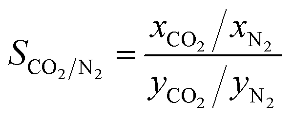 | (2) |
:1, so there is no partial pressure. According to eqn (2), in DHP and Me2F membranes, the solubility selectivity is 5.30 (±0.27) and 4.71 (±0.08), respectively.
3.3 Permeation behaviours of the CO2/N2 mixture through membranes
To assess the impact of gas diffusion on the performance of separation membranes, we analysed the dynamic behaviours involved in the diffusion process. By accurately measuring the diffusion rates and interaction conditions of gases within the membrane materials, we can optimize membrane structures and improve their practical performance.Fig. 5a illustrates the relationship between the permeation flux and diffusion time. Initially, N2 diffusion efficiency is higher than that of CO2 because the voids in the PIMs are not yet occupied by CO2. In this early phase, CO2 molecules are adsorbed within the membrane cavities and cannot diffuse readily, whereas N2, experiencing weaker interactions with the membrane, moves more freely. As the simulation progresses, CO2 adsorption reaches saturation (see Fig. 4a), fully occupying the membrane's voids. After further gas adsorption, the permeability efficiency of CO2 was significantly higher than that of N2, showing a linear increase. Furthermore, the Me2F membrane demonstrates a superior permeation rate compared to DHP. The rate of gas migration serves as an effective metric for gauging the diffusion velocity of gas molecules moving within a membrane. This parameter reflects the dynamic characteristics of the movement of gas molecules within the separation membrane medium, offering a quantitative basis for evaluating the efficiency of gas diffusion through the membrane. The migration rate of gas molecules in membranes can be determined by the mean square displacement function (MSD), which can be expressed as:
 | (3) |
 | (4) |
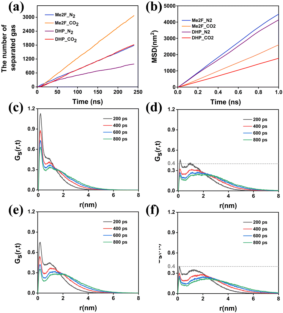 | ||
| Fig. 5 (a) Permeation numbers of CO2 and N2 molecules versus simulation time in Me2F and DHP membranes. (b) Mean square displacement (MSD) of gas molecules in membranes. (c) The van Hove function for CO2 in DHP; (d) N2 in DHP; (e) CO2 in Me2F; (f) N2 in Me2F. | ||
MDAnalysis68 was used to analyse the MSD of gas molecules within the system, allowing us to calculate their diffusion coefficients. Table 2 presents these diffusion coefficients for gas molecules at 308 K, as determined by eqn (4). These values are averaged from three independent simulations. Fig. 5b shows that the permeability coefficient of CO2 is significantly lower than that of N2, indicating a much lower migration rate for CO2 within the membrane. Based on this, one might consider that the membrane's selectivity favours N2 over CO2. However, both experimental and simulation results reveal the opposite: the membrane demonstrates higher selectivity for CO2.34
| Gas | DHP (10−5 cm2 s−1) | Me2F (10−5 cm2 s−1) |
|---|---|---|
| CO2 | 301.44 (±9.13) | 424.77 (±60.95) |
| N2 | 703.99 (±67.68) | 758.66 (±41.25) |
To understand the unexpected appearance and further explore the transport mechanisms of gas molecules within the membrane, their transport behaviours were analysed using the van Hove correlation function, as shown in Fig. 5c–f. This analysis revealed that CO2 and N2 molecules exhibit distinct diffusion mechanisms in the two types of membranes. The van Hove function displays two distinct peaks for both gases. The first peak corresponds to the local motion of gas molecules, while the second peak indicates their diffusion motion over longer distances. For CO2, the first peak is located at 0.1 nm, suggesting that CO2's movement is significantly restricted within the membrane structure. In contrast, while N2 also shows a characteristic peak at 0.1 nm, its intensity is much lower than that of CO2, indicating that N2's local motion is less constrained. The second peak, associated with long-range movements, is located at greater distances and has broader shape. As simulation time progresses, these peaks shift further outward, illustrating the transition of gas molecules from localized movements to long-range diffusion. Comparing the second peaks of CO2 and N2 reveals that N2 experiences more dominant long-range movements, which aligns well with the observed diffusion results. This suggests that despite CO2's higher selectivity in the membrane, N2 has a greater propensity for long-range diffusion, which is in good agreement with our diffusion results.
Comparing the van Hove correlation function for the same gas species across different types of separation membranes reveals notable differences in their transport behaviors. For CO2, the first peak in DHP membranes is more pronounced compared to Me2F, indicating that CO2 experiences greater constraints within DHP. This suggests that because of these limitations, CO2 in DHP is more difficult to diffuse out of the membrane than CO2 in Me2F. Similarly, the diffusion behavior of N2 across both membrane types follows a pattern akin to CO2. DHP imposes more significant restrictions on N2, whereas in Me2F, N2 experiences more extensive jumps. This results in a more pronounced diffusion effect for N2 in Me2F compared to DHP.
Within the same type of membrane, N2 experiences fewer restrictions compared to CO2 and primarily follows classical Fickian diffusion kinetics. This suggests that N2's diffusion behavior is dominated by free diffusion, with hopping mechanisms playing a secondary role. Conversely, CO2 moves shorter distances over the same period due to stronger constraints, indicating that for CO2, the hopping mechanism is primary, while diffusion is secondary. This highlights that the two gases exhibit distinct transport mechanisms. In both types of membranes, Me2F demonstrates higher permeation flux as it imposes relatively weaker constraints on gas molecules, as shown in Fig. 5a.
To gain insights into the reasons behind these different diffusion mechanisms, the RDF was used to analyze the interactions between gas molecules and the PIMs, as well as the changes in coordination numbers of the gas molecules dispersed within the membranes. Fig. 6 shows that the RDFs of these two gas molecules in the two membranes have the same shape. Compared to Me2F, DHP exhibits the peak at the same position, indicating that both membranes have a close degree of coordination tightness for gases. By integrating the area under the RDF curve within the shell radius, the coordination number of CO2 and N2 molecules in the DHP membrane is 2.47 and 1.17, and 2.65 and 1.73 in the Me2F membrane, respectively. The coordination numbers of the two gases are obviously different in different membranes, which reflects that the both membranes can better separate CO2/N2.
 | ||
| Fig. 6 RDFs (solid lines) and CNs (dashed lines) between the characteristic atom CX and gas molecules in (a) DHP and (b) Me2F membranes. | ||
To further compare the differences between the two models, we calculated the residence times of gas molecules. The auto-correlation function (ACF) of the residence time can represent the probability of a group of particles staying in the specified region or the survival probability (SP). The decay speed can reflect the kinetic state of the particles by eqn (5), where t is the time step, N(t0) is the number of gas molecules in the specified region at time t0, and N(t0,t0 + t) is the number of gas molecules in each frame between t0 and t0 + t. The angle bracket indicates that the ensemble average is taken for the initial value t0 at all times.
 | (5) |
Using eqn (6) to fit the ACF, the average residence time of the particles in the specified region can be obtained.
 | (6) |
Fig. 7 illustrates the survival probability of gas molecules within the membrane. In DHP, the average retention time for CO2 and N2 is 18.10 ps and 11.17 ps, respectively. In contrast, the retention time increases to 26.52 ps for CO2 and 13.89 ps for N2 in Me2F. These data indicate that CO2's movement is more restricted compared to N2, making CO2 permeation through these membranes more challenging.
 | ||
| Fig. 7 Residence autocorrelation function of the retention time of gas molecules in the PIM membrane. | ||
In order to quantify the interaction between gas molecules and membranes, the interaction energy is calculated and shown in Fig. 8. We can see that the van der Waals and coulomb interactions between CO2 and the membrane are much larger than that of N2, and the membrane is more selective to CO2. This finding is consistent with the experimental result.34 Based on the above simulation results of the gas adsorption process, we can obtain that the adsorption effect of CO2 is stronger than that of N2. That is say, the diffusion effect was weaker than that of N2. But a contrary conclusion between experimental and simulation results was obtained, where the permeation effect of CO2 is greater than that of N2. To unveil this contradictory phenomenon, we calculated the binding strength between gas molecules by quantum chemistry calculations. As shown in Fig. 9, the binding energies of CO2–CO2, N2–N2 and CO2–N2 are −2.47, −0.71, and −1.40 kcal mol−1, respectively. The interaction region indicator (IRI) analysis (Fig. 10) shows that the binding energy is mainly derived from the van der Waals interaction between carbon and oxygen atoms. According to the binding strength order, we can infer that CO2 molecules tend to form CO2 clusters, and CO2 molecules are not transported as a single molecule in the membrane during diffusion separation. Through the trajectory movie shown in Fig. S4 (ESI†), we preliminarily confirm the existence of CO2 molecular clusters. It also reflects the reason why CO2 is more restricted in the membrane.
 | ||
| Fig. 8 van der Waals interaction and coulomb interaction energy between gas and membranes. | ||
 | ||
| Fig. 9 Binding energy of CO2–CO2, N2–N2 and CO2–N2. | ||
 | ||
| Fig. 10 The interaction region indicator analysis of the CO2 dimer. | ||
To address the discrepancy between the observed diffusion rates and selectivity of gases, it's important to consider both adsorption and diffusion kinetics. Although N2 diffuses faster, CO2 exhibits greater selectivity due to its stronger interaction with the membrane, which affects both adsorption and diffusion processes. Based on the solution–diffusion mechanism, the permeability P in polymer membranes can be expressed as:
| P = S × D | (7) |
The separation factor between two substances i and j in the membrane is typically assessed through the ideal permeation selectivity.35
| ai/j = Pi/j = Si/j × Di/j | (8) |
| i = CO2, j = N2 | S i/Sj | D i/Dj | P i/Pj |
|---|---|---|---|
| DHP | 5.30 (±0.27) | 0.43 (±0.01) | 2.27 (±0.18) |
| Me2F | 4.71 (±0.08) | 0.56 (±0.05) | 2.63(±0.29) |
4 Conclusion and outlook
In this work, molecular dynamics simulations were conducted to investigate the separation of CO2/N2 mixtures in two types of microporous hydrocarbon ladder polymer membranes. The mechanism of gas separation was revealed by analysing the pore size, structure and kinetic and thermodynamic data of the polymers. According to the separation process, we divide the whole process into two key stages: adsorption and separation. During the initial adsorption stage, CO2 gas rapidly diffused into the membrane and attained equilibrium, while N2 maintained a relatively lower permeation level. Once CO2 permeation reached equilibrium, its diffusion efficiency will exceed that of N2. Both membranes demonstrated high selectivity for CO2 gases, primarily attributed to solubility selectivity. In the second stage, CO2 predominantly utilized a hopping mechanism and secondary diffusion mechanism to permeate through the membrane. However, N2 mainly followed a traditional diffusion mechanism and an auxiliary hopping mechanism. Moreover, through the calculation of interaction energy between gas molecules and membranes, we found that CO2 tends to form clusters in membranes. Finally, the selectivity of Me2F to CO2/N2 was 2.63, and that of DHP to CO2/N2 was 2.27. Both membranes showed greater solubility selectivity than diffusion selectivity. That is, CO2/N2 through new PIMs mainly conforms to the solution–selective separation mechanism. The current work provides a theoretical basis for the design and manufacture of high-performance membranes.In this work, the absolute values of the ideal selectivity in the experiment and simulation have a certain deviation (Table S4 and Fig. S5, ESI†). The discrepancy may primarily stem from variations in the driving pressure applied in experiments and simulations. Additionally, potential inaccuracies in the force field parameters cannot be entirely ruled out. In experiments, PIM membranes are inherently heterogeneous, whereas our simulations utilized periodic boundary conditions, simplifying the intricate and multiscale structure of real membranes. Despite efforts to replicate experimental conditions during model construction, the idealized treatment of the PIM membrane model likely contributed to these inconsistencies. The accuracy of the force field is paramount for accurately describing intermolecular interactions, particularly when applied to heterogeneous materials like PIM membranes. Future research could benefit from exploring machine learning-based force fields (MLFFs) specifically tailored for PIM membranes, alongside advanced modeling techniques, to enhance simulation accuracy. MLFFs, trained on high-precision quantum chemical data, offer the potential to better describe weak interactions and adapt to the complexity of heterogeneous materials. Implementing these advancements could significantly improve the precision and reliability of PIM membrane simulations, paving the way for more accurate predictive models in membrane science.
Author contributions
W. X. Tian: data curation, formal analysis, investigation, methodology, software, validation, visualization, writing – original draft, writing – review & editing. L. D. Gong: conceptualization, data curation, formal analysis, investigation, methodology, software, project administration, resources, supervision, writing – review & editing. C. Y. Yu: conceptualization, data curation, formal analysis, investigation, methodology, software, project administration, resources, supervision, writing – review & editing. Y. F. Zhou: conceptualization, project administration, resources, supervision, writing – review & editing.Data availability
The data that support the findings of this study are available from the corresponding author upon reasonable request.Conflicts of interest
There are no conflicts to declare.Acknowledgements
The authors acknowledge the financial support from the National Natural Science Foundation of China (No. 22377048). We gratefully acknowledge HZWTECH for providing computation facilities.Notes and references
- L. Al-Ghussain, Environ. Prog. Sustainable Energy, 2018, 38, 13–21 CrossRef.
- A. Dutton, A. E. Carlson, A. J. Long, G. A. Milne, P. U. Clark, R. DeConto, B. P. Horton, S. Rahmstorf and M. E. Raymo, Science, 2015, 349, aaa4019 CrossRef PubMed.
- K. J. Kroeker, R. L. Kordas, R. Crim, I. E. Hendriks, L. Ramajo, G. S. Singh, C. M. Duarte and J. P. Gattuso, Global Change Biol., 2013, 19, 1884–1896 CrossRef PubMed.
- C. G. Bezzu, M. Carta, A. Tonkins, J. C. Jansen, P. Bernardo, F. Bazzarelli and N. B. McKeown, Adv. Mater., 2012, 24, 5930–5933 CrossRef PubMed.
- M. Carta, R. Malpass-Evans, M. Croad, Y. Rogan, J. C. Jansen, P. Bernardo, F. Bazzarelli and N. B. McKeown, Science, 2013, 339, 303–307 CrossRef PubMed.
- B. S. Ghanem, R. Swaidan, X. Ma, E. Litwiller and I. Pinnau, Adv. Mater., 2014, 26, 6696–6700 CrossRef PubMed.
- B. Comesaña-Gándara, J. Chen, C. G. Bezzu, M. Carta, I. Rose, M.-C. Ferrari, E. Esposito, A. Fuoco, J. C. Jansen and N. B. McKeown, Energy Environ. Sci., 2019, 12, 2733–2740 RSC.
- R. Swaidan, B. Ghanem and I. Pinnau, ACS Macro Lett., 2015, 4, 947–951 CrossRef PubMed.
- P. M. Budd, B. S. Ghanem, S. Makhseed, N. B. McKeown, K. J. Msayib and C. E. Tattershall, Chem. Commun., 2004, 230–231 RSC.
- P. M. Budd, E. S. Elabas, B. S. Ghanem, S. Makhseed, N. B. McKeown, K. J. Msayib, C. E. Tattershall and D. Wang, Adv. Mater., 2004, 16, 456–459 CrossRef CAS.
- L. M. Robeson, J. Membr. Sci., 2008, 320, 390–400 CrossRef CAS.
- W. F. Yong, F. Y. Li, Y. C. Xiao, P. Li, K. P. Pramoda, Y. W. Tong and T. S. Chung, J. Membr. Sci., 2012, 407–408, 47–57 CrossRef CAS.
- N. Du, G. P. Robertson, J. Song, I. Pinnau and M. D. Guiver, Macromolecules, 2009, 42, 6038–6043 CrossRef CAS.
- J. Weber, N. Du and M. D. Guiver, Macromolecules, 2011, 44, 1763–1767 CrossRef CAS.
- C. R. Mason, L. Maynard-Atem, N. M. Al-Harbi, P. M. Budd, P. Bernardo, F. Bazzarelli, G. Clarizia and J. C. Jansen, Macromolecules, 2011, 44, 6471–6479 CrossRef CAS.
- N. Du, H. B. Park, G. P. Robertson, M. M. Dal-Cin, T. Visser, L. Scoles and M. D. Guiver, Nat. Mater., 2011, 10, 372–375 CrossRef PubMed.
- N. Du, G. P. Robertson, M. M. Dal-Cin, L. Scoles and M. D. Guiver, Polymer, 2012, 53, 4367–4372 Search PubMed.
- H. A. Patel and C. T. Yavuz, Chem. Commun., 2012, 48, 9989–9991 RSC.
- N. Du, M. M. D. Cin, I. Pinnau, A. Nicalek, G. P. Robertson and M. D. Guiver, Macromol. Rapid Commun., 2011, 32, 631–636 CrossRef PubMed.
- N. Du, M. M. Dal-Cin, G. P. Robertson and M. D. Guiver, Macromolecules, 2012, 45, 5134–5139 CrossRef.
- F. Y. Li, Y. Xiao, T.-S. Chung and S. Kawi, Macromolecules, 2012, 45, 1427–1437 CrossRef.
- T. Emmler, K. Heinrich, D. Fritsch, P. M. Budd, N. Chaukura, D. Ehlers, K. Rätzke and F. Faupel, Macromolecules, 2010, 43, 6075–6084 CrossRef.
- J. Ahn, W.-J. Chung, I. Pinnau, J. Song, N. Du, G. P. Robertson and M. D. Guiver, J. Membr. Sci., 2010, 346, 280–287 CrossRef.
- A. F. Bushell, M. P. Attfield, C. R. Mason, P. M. Budd, Y. Yampolskii, L. Starannikova, A. Rebrov, F. Bazzarelli, P. Bernardo, J. Carolus Jansen, M. Lanč, K. Friess, V. Shantarovich, V. Gustov and V. Isaeva, J. Membr. Sci., 2013, 427, 48–62 CrossRef.
- A. F. Bushell, P. M. Budd, M. P. Attfield, J. T. A. Jones, T. Hasell, A. I. Cooper, P. Bernardo, F. Bazzarelli, G. Clarizia and J. C. Jansen, Angew. Chem., Int. Ed., 2012, 52, 1253–1256 CrossRef PubMed.
- C. Das Neves Gomes, O. Jacquet, C. Villiers, P. Thuéry, M. Ephritikhine and T. Cantat, Angew. Chem., Int. Ed., 2011, 51, 1 CrossRef.
- M. G. De Angelis, R. Gaddoni and G. C. Sarti, Ind. Eng. Chem. Res., 2013, 52, 10506–10520 CrossRef.
- M. M. Khan, V. Filiz, G. Bengtson, S. Shishatskiy, M. M. Rahman, J. Lillepaerg and V. Abetz, J. Membr. Sci., 2013, 436, 109–120 CrossRef.
- M. Carta, K. J. Msayib, P. M. Budd and N. B. McKeown, Org. Lett., 2008, 10, 2641–2643 CrossRef.
- D. Fritsch, G. Bengtson, M. Carta and N. B. McKeown, Macromol. Chem. Phys., 2011, 212, 1137–1146 CrossRef.
- B. S. Ghanem, Polym. Chem., 2012, 3, 96–98 RSC.
- S. Li, H. J. Jo, S. H. Han, C. H. Park, S. Kim, P. M. Budd and Y. M. Lee, J. Membr. Sci., 2013, 434, 137–147 CrossRef.
- K. Mizrahi Rodriguez, F. M. Benedetti, N. Roy, A. X. Wu and Z. P. Smith, J. Mater. Chem. A, 2021, 9, 23631–23642 RSC.
- H. W. H. Lai, F. M. Benedetti, J. M. Ahn, A. M. Robinson, Y. Wang, I. Pinnau, Z. P. Smith and Y. Xia, Science, 2022, 375, 1390–1392 CrossRef PubMed.
- W. Fang, L. Zhang and J. Jiang, Mol. Simul., 2010, 36, 992–1003 CrossRef.
- K. E. Hart, L. J. Abbott, N. B. McKeown and C. M. Colina, Macromolecules, 2013, 46, 5371–5380 CrossRef.
- J. Liu and J. Jiang, J. Phys. Chem. C, 2019, 123, 6607–6615 CrossRef.
- Z. Zhao and J. Jiang, J. Membr. Sci., 2020, 608, 118173 CrossRef.
- M. J. Abraham, T. Murtola, R. Schulz, S. Páll, J. C. Smith, B. Hess and E. Lindahl, SoftwareX, 2015, 1–2, 19–25 CrossRef.
- G. S. Larsen, P. Lin, K. E. Hart and C. M. Colina, Macromolecules, 2011, 44, 6944–6951 CrossRef.
- B. Ma, C. Chen, Z.-X. Du and L. Zhang, J. Mol. Liq., 2023, 386, 122362 CrossRef.
- X. Kong and J. Liu, J. Phys. Chem. C, 2019, 123, 15113–15121 CrossRef CAS.
- K. E. Hart, L. J. Abbott and C. M. Colina, Mol. Simul., 2013, 39, 397–404 CrossRef CAS.
- J. Wang, R. M. Wolf, J. W. Caldwell, P. A. Kollman and D. A. Case, J. Comput. Chem., 2004, 25, 1157–1174 CrossRef CAS PubMed.
- N. Lubna, G. Kamath, J. J. Potoff, N. Rai and J. I. Siepmann, J. Phys. Chem. B, 2005, 109, 24100–24107 CrossRef CAS.
- M. G. Martin and J. I. Siepmann, J. Phys. Chem. B, 1998, 102, 2569–2577 CrossRef CAS.
- N. Rai and J. I. Siepmann, J. Phys. Chem. B, 2007, 111, 10790–10799 CrossRef CAS.
- C. D. Wick, J. M. Stubbs, N. Rai and J. I. Siepmann, J. Phys. Chem. B, 2005, 109, 18974–18982 CrossRef CAS.
- S. Nosé, Mol. Phys., 2006, 52, 255–268 CrossRef.
- M. Parrinello and A. Rahman, J. Appl. Phys., 1981, 52, 7182–7190 CrossRef CAS.
- W. Liu, G. Hong, D. Dai, L. Li and M. Dolg, Theor. Chem. Acc., 1997, 96, 75–83 Search PubMed.
- W. Liu, F. Wang and L. Li, Recent Advances in Relativistic Molecular Theory, World Scientific, Singapore, 2004, vol. 5, pp. 257–282 Search PubMed.
- W. Liu, F. Wang and L. Li, J. Theor. Comput. Chem., 2011, 02, 257–272 CrossRef.
- Z. Wang, Z. Li, Y. Zhang and W. Liu, J. Chem. Phys., 2020, 153, 164109 CrossRef CAS PubMed.
- Y. Zhang, B. Suo, Z. Wang, N. Zhang, Z. Li, Y. Lei, W. Zou, J. Gao, D. Peng, Z. Pu, Y. Xiao, Q. Sun, F. Wang, Y. Ma, X. Wang, Y. Guo and W. Liu, J. Chem. Phys., 2020, 152, 064113 CrossRef PubMed.
- Hongzhiwei Technology, Device Studio, Version 2023A, China, 2023, Available online: https://cloud.hzwtech.com/web/pro-ductservice?id=6 (accessed on Aug., 23rd) Search PubMed.
- T. Lu and Q. Chen, Chem.: Methods, 2021, 1, 231–239 CAS.
- T. Lu and F. Chen, J. Comput. Chem., 2011, 33, 580–592 CrossRef PubMed.
- K. E. Jelfs and A. I. Cooper, Curr. Opin. Solid State Mater. Sci., 2013, 17, 19–30 CrossRef CAS.
- N. B. McKeown and P. M. Budd, Macromolecules, 2010, 43, 5163–5176 CrossRef CAS.
- T. F. Willems, C. H. Rycroft, M. Kazi, J. C. Meza and M. Haranczyk, Microporous Mesoporous Mater., 2012, 149, 134–141 CrossRef CAS.
- S. Matteucci, Y. Yampolskii, B. D. Freeman and I. Pinnau, Mater. Sci. Membr. Gas Vap. Sep., 2006, 1–47 CAS.
- L. Sarkisov and A. Harrison, Mol. Simul., 2011, 37, 1248–1257 CrossRef CAS.
- N. Mehio, S. Dai and D.-E. Jiang, J. Phys. Chem. A, 2014, 118, 1150–1154 CrossRef CAS PubMed.
- D. A. Gómez-Gualdrón, P. Z. Moghadam, J. T. Hupp, O. K. Farha and R. Q. Snurr, J. Am. Chem. Soc., 2016, 138, 215–224 CrossRef PubMed.
- L. Brochard, M. Vandamme, R. J. Pellenq and T. Fen-Chong, Langmuir, 2012, 28, 2659–2670 CrossRef CAS PubMed.
- J. Sun, C. Chen, Y. Zhang, W. Li and Y. Song, Chem. Eng. J., 2022, 430, 133172 CrossRef CAS.
- N. Michaud-Agrawal, E. J. Denning, T. B. Woolf and O. Beckstein, J. Comput. Chem., 2011, 32, 2319–2327 CrossRef CAS PubMed.
Footnote |
| † Electronic supplementary information (ESI) available. See DOI: https://doi.org/10.1039/d4cp04588b |
| This journal is © the Owner Societies 2025 |