
 Open Access Article
 This Open Access Article is licensed under a
 Creative Commons Attribution 3.0 Unported Licence
Phase field simulations of thermal annealing for all-small molecule organic solar cells†
Yasin
Ameslon
 *a,
Olivier J. J.
Ronsin
a,
Christina
Harreiß
b,
Johannes
Will
b,
Stefanie
Rechberger
b,
Mingjian
Wu
b,
Erdmann
Spiecker
b and
Jens
Harting
ac
*a,
Olivier J. J.
Ronsin
a,
Christina
Harreiß
b,
Johannes
Will
b,
Stefanie
Rechberger
b,
Mingjian
Wu
b,
Erdmann
Spiecker
b and
Jens
Harting
ac
aHelmholtz Institute Erlangen-Nürnberg for Renewable Energy, Forschungszentrum Jülich, Fürther Strasse 248, 90429 Nürnberg, Germany. E-mail: y.ameslon@fz-juelich.de
bInstitute of Micro- and Nanostructure Research (IMN) & Center for Nanoanalysis and Electron Microscopy (CENEM), Interdisciplinary Center for Nanostructured Films (IZNF), Department of Materials Science and Engineering, Friedrich-Alexander-Universität Erlangen-Nürnberg, Cauerstrasse 3, 91058 Erlangen, Germany
cDepartment of Chemical and Biological Engineering and Department of Physics, Friedrich-Alexander-Universität Erlangen-Nürnberg, Cauerstrasse 1, 91058 Erlangen, Germany
First published on 16th December 2024
Abstract
Interest in organic solar cells (OSCs) is constantly rising in the field of photovoltaic devices. The device performance relies on the bulk heterojunction (BHJ) nanomorphology, which develops during the drying process and additional post-treatment. This work investigates the effect of thermal annealing (TA) on the all-small molecule DRCN5T:PC71BM blend with phase field simulations. The objective is to determine the physical phenomena driving the evolution of the BHJ morphology for a better understanding of the post-treatment/morphology relationship. Phase-field simulation results are used to investigate the impact on the final BHJ morphology of the DRCN5T crystallization-related mechanisms, including nucleation, growth, crystal stability, impingement, grain coarsening, and Ostwald ripening, of the amorphous–amorphous phase separation (AAPS), and of diffusion limitations. The comparison of simulation results with experimental data shows that the morphological evolution of the BHJ under TA is dominated by dissolution of the smallest, unstable DRCN5T crystals and anisotropic growth of the largest crystals.
1. Introduction
Organic solar cells (OSCs) have the potential to become the cheapest electricity source, even cheaper than silicon based solar cells. This potential comes from the ability to coat large areas quickly and at very low costs using printing methods.1,2 In addition, they represent an excellent option for fabricating flexible, light-weight, and semi-transparent solar cells, which opens the way to applications for building integrated photovoltaics, agrivoltaics or portable electronics.2–4 In order to ensure charge carrier separation, OSC absorber layers are composed of two materials, one electron donor and one electron acceptor, which might be polymers or small molecules. Recently, the development of non-fullerene acceptor small molecules, particularly Y6 and its derivatives, led to OSCs reaching 19% power conversion efficiency (PCE) with polymer donors.5 On the other hand, OSCs with a small-molecule donor, the so-called all-small molecule (ASM) solar cells, have recently reached a PCE of around 18%.6 As compared to polymer OSCs, ASM OSCs still suffer from slightly lower PCE, shorter lifetime and scalability problems due to the need for posttreatment methods such as thermal annealing (TA) or solvent vapor annealing (SVA) to obtain high PCE.1,6–10 However, ASM OSCs have crucial advantages as compared to polymer OSCs, such as better batch-to-batch reproducibility, high purity, and better processability due to their comparatively higher solubilities.3,6 The versatility of the available chemical structures results in improved energy level control compared to polymers.10 Additionally, the strong intermolecular interactions and crystallinity in these systems result in high open circuit voltages and electron mobilities.7,8 Thus ASM absorber layers represent a promising option for future development of OSCs, but their efficiency and stability still need to be improved and better understood.In order to reach decent performances, OSC absorber layers must form complex structures, the so-called bulk heterojunction (BHJ) morphologies.11,12 Thereby, separated donor and acceptor phases form bicontinuous interpenetrating pathways at the nanometer scale. This allows for efficient dissociation of the excitons, which have a very short mean free path in such dielectric materials, and for efficient hole and electron transport in the donor and acceptor phases, respectively.13–16 Moreover, crystalline phases are desirable to ensure high charge carrier mobilities. The BHJ forms during the fabrication process (coating and further processing steps such as solvent vapor annealing (SVA) or thermal annealing (TA)), so that the processing conditions have a significant impact on the BHJ morphology and thus on the optoelectronic performances.11 It is therefore interesting to control the morphological features of the BHJ, and for this it is desirable to understand the physical mechanisms driving its formation.
This paper focuses on understanding the morphology formation mechanisms of an ASM photoactive layer upon thermal annealing. The investigated system is a blend of DRCN5T [2,2′-[(3,3′′′,3′′′′,4′-tetraoctyl[2,2′:5′,2′′:5′′,2′′′:5′′′,2′′′′-quinquethiophene]-5,5′′′′-diyl)bis[(Z)-methylidyne(3-ethyl-4-oxo-5,2-thiazolidinediylidene)]]bis-propanedinitrile], an oligophiene small molecule donor and PC71BM [[6,6]-phenyl-C71-butyric acid methyl ester], a fullerene acceptor small molecule. Although newer materials allow for better performance, the energy level matching for these molecules still allows the PCE to reach 10%.4 Most importantly, this system has been studied in detail over the past years, giving access to substantial amounts of quantitative, precise and usable data on active layer morphology and formation mechanisms. In particular, energy-filtered transmission electron microscopy (EFTEM) investigations allowed us to extract characteristic information on the nanomorphology of the BHJ and analyze the relationship between the post-treatment conditions, the morphology and solar cell performance: a detailed analysis of the microstructure of the DRCN5T crystal fiber lengths and widths for SVA with various solvents, and under different TA temperatures, brought insight into the optimal crystal length leading to the highest PCE.8,9,17–21 Crystals must be sufficiently large to provide sufficient phase separation and high mobilities, but not too large, in order to ensure proper exciton dissociation.8 However, the process–structure relationship is still not fully unravelled. Therefore, this article aims to shed light on the physical phenomena responsible for the BHJ morphologies observed experimentally in DRCN5T:PC71BM absorber layers, using advanced simulations. Thereby, we focus on the effect of TA post-treatments at different temperatures.8,9,17–21
Numerous methods can be used for the simulation of complex phase transformation processes like the ones encountered during the formation of a BHJ. Atomistic, molecular dynamics (MD) or Monte Carlo (MC) simulations can provide insights at the molecular level, but they are time-consuming and restricted to small-scale systems. Continuum mechanics simulation models such as the phase field (PF) approach allow solving such problems at the mesoscopic level with a reasonable computational effort.22 PF simulations can provide insight into morphology formation and evolution, into the different phase states, and into the phase transitions during a given process. The intermediate and final states of the morphology can thus be calculated and predicted. The PF approach can describe crystallization,23–32 including nucleation,22 isotropic or anisotropic growth, coarsening,33 and complex solidification structures such as dendrites, spherulites, or eutectic patterns.22 It can also be used to simulate amorphous–amorphous phase separation (AAPS).14,23 Since several of these processes may be involved in the morphology formation and evolution of OPV absorber layers, in this paper we propose to use the PF approach to investigate the properties of the DRCN5T:PC71BM blend. All these physical processes can be handled in a PF model recently developed in our group,23–29,31 so that it can be used to identify the mechanisms driving the BHJ formation of DRCN5T:PC71BM blends upon TA.
The objectives of the present work are (1) to successfully simulate the experimentally observed BHJ morphologies and thus validate the applicability of our PF approach for the investigation of ASM OSCs, (2) to study the impact of the different possible physical mechanisms on the BHJ morphology evolution during TA at different temperatures and (3) to identify the physical processes driving the morphology evolution of DRCN5T:PC71BM blends upon TA. In order to do this, we perform PF simulations of the TA process with variable parameters, so as to activate or deactivate the possible physical mechanisms, analyse the consequences on the simulated morphologies and their matching with the measured data.
The remainder of the paper is organized as follows: after an introduction to the methods in Section 2, we describe in Section 3 the results of the simulations, the comparison with the experimental results and the discussions on the drivers of the BHJ formation. Finally, Section 4 contains the conclusions and outlook.
2. Method
2.1. Unravelling BHJ evolution mechanisms with a coupled experimental and simulation approach
In order to unravel the mechanisms driving the BHJ evolution during TA, we first need to determine the different physical phenomena that could potentially be active, the definition of which is concisely given below:• Crystal nucleation: the spontaneous appearance of new, stable crystals (also called nuclei or germs) from thermal fluctuations, driven by the minimization of the free energy of the system upon transition from the amorphous phase to the crystalline phase.
• Crystal growth: the increase in size of a stable crystal, driven by the minimization of the free energy of the system upon transition from the amorphous phase to the crystalline phase. Thereby, crystals take up material from the amorphous phase.
• Diffusion-limited crystal growth: in this case, diffusion in the amorphous phase is too slow to balance for the material uptake by the growing crystals, so that a depletion zone arises in the amorphous phase around the crystals.
• Crystal (in)stability: crystal (in)stability is a result of the balance between bulk energy and surface energy of a single crystal. For a crystal to be stable, the bulk energy gain upon growth must be larger than the surface energy increase, otherwise the crystal dissolves. It can be shown that the nuclei have to reach a critical size to be stable and grow.
• Impingement: crystals impinge when they come in contact and form crystal–crystal interfaces, so-called grain boundaries.
• Ostwald ripening: the growth of the largest crystals at the expense of the smallest ones, for crystals separated from each other by the amorphous phase. Material transfer between crystals occurs by transport (diffusion) through the amorphous phase. Ostwald ripening is driven by the minimization of the overall interface energy of the crystal assembly. Thereby, the energy is reduced if smaller crystals shrink and larger crystals grow.
• Grain coarsening: similar to Ostwald ripening, the growth of the largest crystals at the expense of the smallest ones, driven by the minimization of the overall interface energy of the crystal assembly. However, we will use this term for crystals in contact, whereby material transfer between crystals occurs through the grain boundaries.
• Amorphous–amorphous phase separation: the demixing of the amorphous phase driven by donor–acceptor immiscibility. Demixing may occur by spinodal decomposition or nucleation and growth of amorphous demixed regions.
We investigate the significance of these various phenomena during TA of DRCN5T:PC71BM blends by performing simulations with different sets of material parameters, and then by comparing the simulation results with experimental measurements of the morphology. The idea is as follows: despite the outstanding experimental data available for the studied system in the literature (see Section 2.2), there is still uncertainty regarding some model parameters. Depending on the values of these parameters, the physical phenomena listed above may be active or inactive. Therefore, we vary the undefined parameters on purpose to activate or deactivate independently the physical processes listed above (see Table 2), and then compare the simulated morphologies with experimental data. On the one hand, physical processes inducing a mismatch between the simulated morphology and the experimental observations are concluded to be inactive or negligible during the TA of the DRCN5T:PC71BM film. On the other hand, physical processes responsible for morphologies matching the experimental observations are concluded to be active during the TA of the studied system. At the end, this allows establishing the dominant physical processes driving the morphology evolution, and to finely calibrate the model parameters. Moreover, a comparison of the various simulated morphologies provides a broad general understanding on how crystal nucleation, instability, growth, impingement, grain coarsening, Ostwald ripening, AAPS and diffusion limitations may impact the BHJ morphology.
According to the observations made using EFTEM, the matching between simulations and experiments is evaluated using the following criteria (ref. 8, 21 and Fig. 3):
• There are 2 phases at the end of the TA procedure, namely, the crystalline DRCN5T fibers and the amorphous mixed phase. Even if a broad and weak PC71BM peak can be observed by energy filtered electron diffraction measurements, there is no clear evolution of PC71BM aggregation with time and temperature.8 Further investigations with 4D-scanning confocal electron diffraction measurements showed that the PC71BM phase remains homogeneous.21 Overall, there is no clear experimental evidence that the PC71BM can crystallize or aggregate during the TA of the system.8,9,20,21
• The number of crystals after 10 min of TA decreases with increasing TA temperature.
• The average crystal size increases with increasing TA temperature.
• The crystals conserve their leaf shape upon TA for 10 min.
2.2. Simulation procedure and method
 | (1) |
 is the driving force for crystallization, where Lfus is the heat of fusion, and T and Tm are the temperature and melting temperature, respectively. The energy barrier has a shape given by the double well function g = ϕ2(ϕ − 1)2. An interpolation function p = ϕ2(3 − 2ϕ) ensures a smooth transition between the amorphous and the crystalline states. The second term of the RHS corresponds to the free energy of mixing and includes enthalpic and entropic contributions. R is the ideal gas constant and v0 is the molar volume of the smallest component. The entropic contribution terms are
  where N1 and N2 stand for the molar size of DRCN5T and PC71BM, respectively. The enthalpic contribution terms are φ(1 − φ)χaa + ϕ2φ(1 − φ)χca, where χaa is the amorphous–amorphous interaction parameter and χca is the crystalline–amorphous interaction parameter.28 The third term on the RHS corresponds to the surface energy contributions. ε, εg and κ are surface tensions related to the order parameter gradient, to the gradient of the crystal orientation θ of the crystalline material and to the volume fraction gradients, respectively. Finally, the last term of the RHS
  is a non-physical term introduced for numerical stability purposes, whereby k is a constant value chosen to be small enough to avoid any significant impact on the simulated physical phenomena.12,31,34
The order parameter and volume fraction time evolution are governed by the stochastic Allen–Cahn (AC) and Cahn–Hilliard (CH) kinetic equations, respectively:
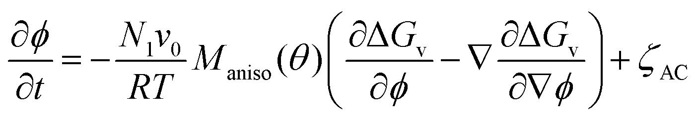 | (2) |
 | (3) |
The growth of DRCN5T fibers is anisotropic, thus requiring an orientation-dependent implementation of at least one relevant growth parameter. Anisotropic crystallization of DRCN5T is due to a preferential spatial arrangement of the molecules in one direction which cannot be accounted for through continuum mechanics models such as the PF. However crystal anisotropy can be modelled with the PF phenomenologically.35 Commonly, the anisotropy is included through the AC mobility Maniso and/or the surface tension parameter ε.36,37 In this work, the anisotropy was implemented on the AC mobility Maniso for simplicity, which is given by
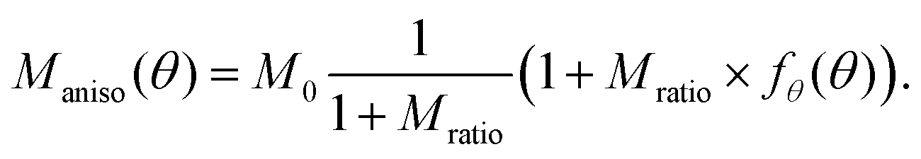 | (4) |
 | (5) |
 . Other anisotropy functions have been evaluated, but the function above models the anisotropic behavior of DRCN5T crystallization in the DRCN5T:PC71BM blend observed in the EFTEM measurements most accurately based on the criteria of conservation of the principal-to-minor axis ratio during growth and the reproduction of the anisotropic leaf-like shape observed experimentally (see Section S1 in the ESI†).
Finally, we can choose between the slow and fast mode dependencies for the Onsager mobility λ for the self-diffusion coefficients.38,39 This work uses the slow mode theory so that the slowest component controls diffusion. The expression of the Onsager mobility is then 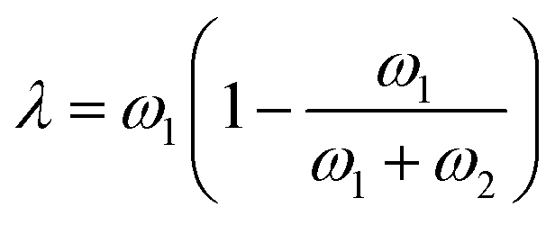 , where ω1 = N1φDs,1(φ,ϕ) and ω2 = N2(1 − φ)Ds,2(φ,ϕ). The self-diffusion coefficients of DRCN5T and PC71BM are calculated using the Vignes’ law,
 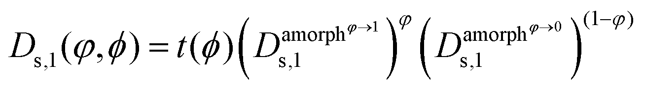 and
and  , respectively. Thereby,
  ,
,  ,
,  and
and  are the self-diffusion coefficients of DRCN5T in its pure amorphous phase, of DRCN5T in a pure amorphous PC71BM phase, of PC71BM in its pure amorphous phase, and of PC71BM in a pure amorphous DRCN5T phase. t is a penalty function that decreases the value of the self-diffusion coefficient when the crystallinity ϕ increases.31
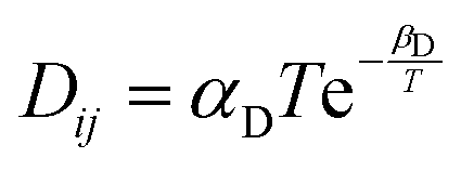
 , where kB is the Boltzmann constant, and rp is the radius of a spherical particle moving in an amorphous matrix of viscosity η. The matrix viscosity η follows an Arrhenius law
 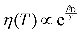 ,45 which leads to
  , where αD and βD are constants. The mobility Maniso is assumed to follow a similar Arrhenius law because crystal growth results from the mobility of the species attaching to the crystal interface.47 The temperature dependency is attributed through the coefficient
 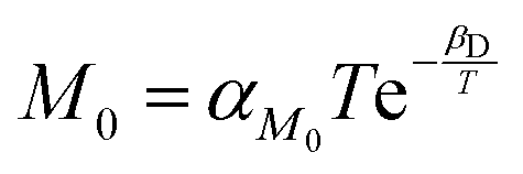 , where αM0 is a constant coefficient. The amorphous–amorphous interaction parameter χaa follows the empirical law
 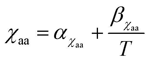 where αχaa and βχaa are constant coefficients.46αχaa and
  represent the entropic and enthalpic part of the interaction parameter, respectively. The crystalline–amorphous interaction parameter χca is chosen to be inversely proportional to the temperature,
 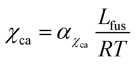 , as proposed by Matkar and Kyu,29 where αχca is a constant. Finally, the surface tension coefficient is assumed to evolve as
  and the energy barrier as Wfus = αWT as described in Table 1. As a result, the crystal interface thickness
  is constant and the surface energy
  increases linearly with temperature. The temperature dependencies of ε, Wfus, and σ, and the fact that the interface thickness does not evolve with temperature, is consistent with molecular dynamics simulations.22,30,48,49αε and αW are constant coefficients. Table 1 summarizes the temperature dependency of the parameters.
| Parameter | Temperature dependency |
|---|---|
| Self-diffusion coefficients |
 [ref. 45] [ref. 45] |
| Mobility coefficient |

|
| Amorphous–amorphous interaction parameter |
 [ref. 46] [ref. 46] |
| Amorphous–crystalline interaction parameter |
 [ref. 29] [ref. 29] |
| Surface tension related to the order parameter gradients |
 [ref. 22] [ref. 22] |
| Energy barrier upon crystallization | W fus = αWT [ref. 22] |
This leaves us with the parameters αD, βD, αM0, αχaa, βχaa, αχca, αε and αW which can be adjusted to match the available experimental data. First of all, for a given material parameter set, the phase diagram of the mixture is calculated and the interaction parameters αχaa, αχca and βχaa are tuned so that the resulting phase diagram (1) matches the experimental liquidus points of the DRCN5T:PC71BM phase diagram,43 and (2) shows a solidus curve with volume fractions close to φ ≈ 1 (pure DRCN5T crystals) at all temperatures. The simulated phase diagrams for a miscible blend (simulations type A, B, C, and E) and for an immiscible blend (simulations type D) are shown in Section S2 of the ESI.† In both cases, the dependence of the melting temperature to volume fraction (melting point depression) is recovered (see Section S2 of the ESI†). Moreover, the parameters αε and αW are chosen to meet two requirements. On the one hand, the interface thickness  spreads over 8 mesh points for appropriate numerical convergence.30 On the other hand, the critical radius is adjusted such that nuclei become unstable at high annealing temperatures: in the current PF simulations, the critical radius is estimated from the classical nucleation theory (CNT). It can be expressed in terms of phase field parameters for 2D simulations of pure isotropic materials as
  (see Section S3 in the ESI†) and is a first indicator for the stability of the ellipsoidal crystals. Indeed, the local radius of curvature should be greater than the critical radius of curvature r* for the crystal interface to propagate. Although the critical radius expression is different in a blend and should, in any case, depend on the volume fraction, this expression is a reasonable first approximation. It indicates a temperature dependency
  . The coefficients αM0 and βD are chosen such that the simulated DRCN5T crystal growth rates match the experimentally measured growth rates, which have been obtained from the time dependence of the crystal widths and lengths measured at the different annealing temperatures. The growths rates are constant over time, as expected for simple growth (see Section S4 of the ESI†).8 Indeed, there should be a match between the experimental and the simulated longitudinal and transversal growth rates of the DRCN5T crystal fibers. Therefore, the mobility coefficient M0 and the ratio Mratio are adjusted to recover the longitudinal and transversal growth rates measured by ex situ measurements.8 The full set of parameters for the different simulations is given in Section S5 of the ESI.†
| Active physical phenomena | Simulation type | ||||
|---|---|---|---|---|---|
| A | B | C | D | E | |
| Crystal growth, Ostwald ripening, and nucleus stability | Yes | Yes | Yes | Yes | Yes |
| Diffusion limitation | No | No | No | No | Yes |
| Crystals impingement | No | Yes | Yes | No | No |
| AAPS | No | No | No | Yes | No |
| Nucleation and grain coarsening | No | No | Yes | No | No |
3. Results and discussions
3.1. Crystal growth, stability and Ostwald ripening
In simulations of type A, only crystal growth, Ostwald ripening, and nucleus stability can play a role. The objective is to determine whether this set of active processes can lead to successful replication of the experimental observations detailed in Section 2.1. This will allow us to conclude whether crystal growth, Ostwald ripening, and nucleus stability are significantly active during the thermal annealing of DRCN5T:PC71BM active layers. The morphology evolution for a TA temperature of 140 °C is shown in Fig. 2 at annealing times of 0 s, 150 s, 300 s, 450 s, 600 s, and 900 s (Fig. 2a). The DRCN5T volume fraction in the crystals is φ ≈ 1 as expected from the DRCN5T:PC71BM solidus line (see Section S2 in the ESI†). Several small crystals dissolve before 300 s of TA (Fig. 2b and c). Starting from 300 s of TA (Fig. 2c), the remaining, stable DRCN5T crystals grow in size, by taking up material from the amorphous phase, as long as the amount of DRCN5T in the amorphous phase is above its equilibrium value. This leads to a progressive and significant decrease of the DRCN5T volume fraction in the amorphous phase until a TA time of 900 s (Fig. 2f). The growth is anisotropic, and the leaf shape of the crystals is conserved for TA times below 600 s (Fig. 2b–e). However, at TA times beyond 600 s, the DRCN5T crystals impinge (Fig. 1f), and their shape is no longer conserved (see Section 3.2).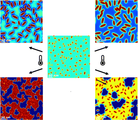 | ||
| Fig. 1 Simulated DRCN5T:PC71BM morphologies under various thermal annealing conditions. The centered image corresponds to the as-cast simulated film, the other images correspond to the morphology after thermal annealing under diffusion limited (top left corner) and normal crystal growth (top right corner) regimes, with nucleation (bottom left corner) and with amorphous–amorphous phase separation (bottom right corner). | ||
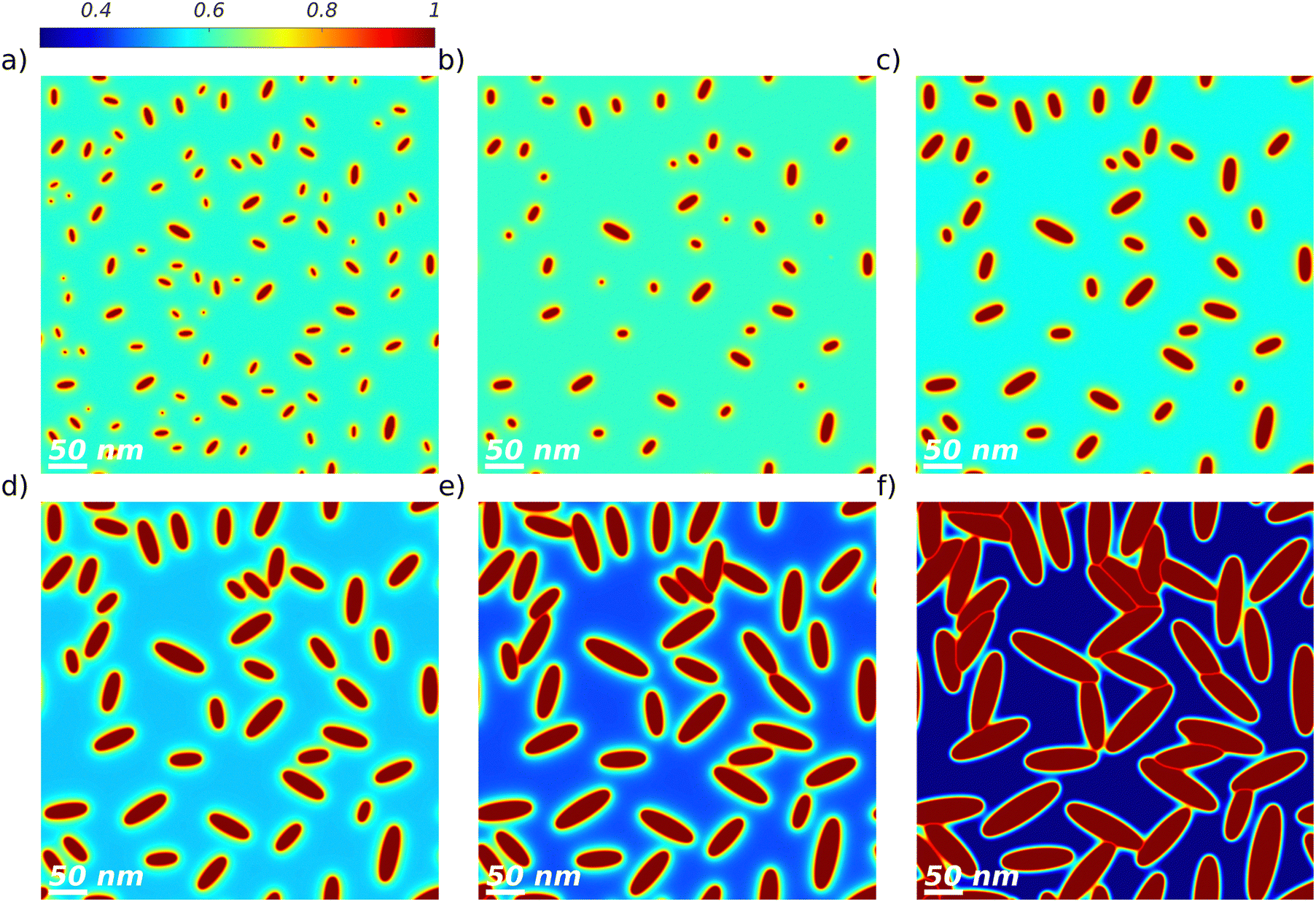 | ||
Fig. 2 TA at 140 °C of a binary DRCN5T![[thin space (1/6-em)]](https://www.rsc.org/images/entities/char_2009.gif) :PC71BM blend with an initial blend ratio of 1:0.8, simulation of type A. The DRCN5T volume fraction fields are shown for the as-cast film with low crystal density (a) and after TA of 150 s (b), 300 s (c), 450 s (d), 600 s (e), and 900 s (f). The volume fraction colorbar spreads from dark blue (low DRCN5T content) to dark red (pure DRCN5T). :PC71BM blend with an initial blend ratio of 1:0.8, simulation of type A. The DRCN5T volume fraction fields are shown for the as-cast film with low crystal density (a) and after TA of 150 s (b), 300 s (c), 450 s (d), 600 s (e), and 900 s (f). The volume fraction colorbar spreads from dark blue (low DRCN5T content) to dark red (pure DRCN5T). | ||
Simulations of type A are performed at temperatures of 80 °C, 100 °C, 120 °C, 140 °C and 160 °C, and the simulated morphologies after 10 min of TA are compared to the EFTEM images in Fig. 3. Even though crystal overlap and the growth of face-on crystals observed in the EFTEM samples are not taken into account in the 2D simulations, the theoretical results nicely match the experimental measurements according to the criteria listed in Section 2.1, namely the presence of 2 phases, the decrease of the number of DRCN5T crystals, the increase of DRCN5T crystal sizes and the conservation of the leaf shape. At 80 °C, crystal growth is very limited (Fig. 3b). In contrast, crystal growth is significant at TA temperatures of 100 °C, 120 °C, 140 °C, and 160 °C (Fig. 3c–f), and the final crystal size increases with increasing temperature. This is due to the nearly exponential temperature dependency of the crystal growth rate (see Section 2).
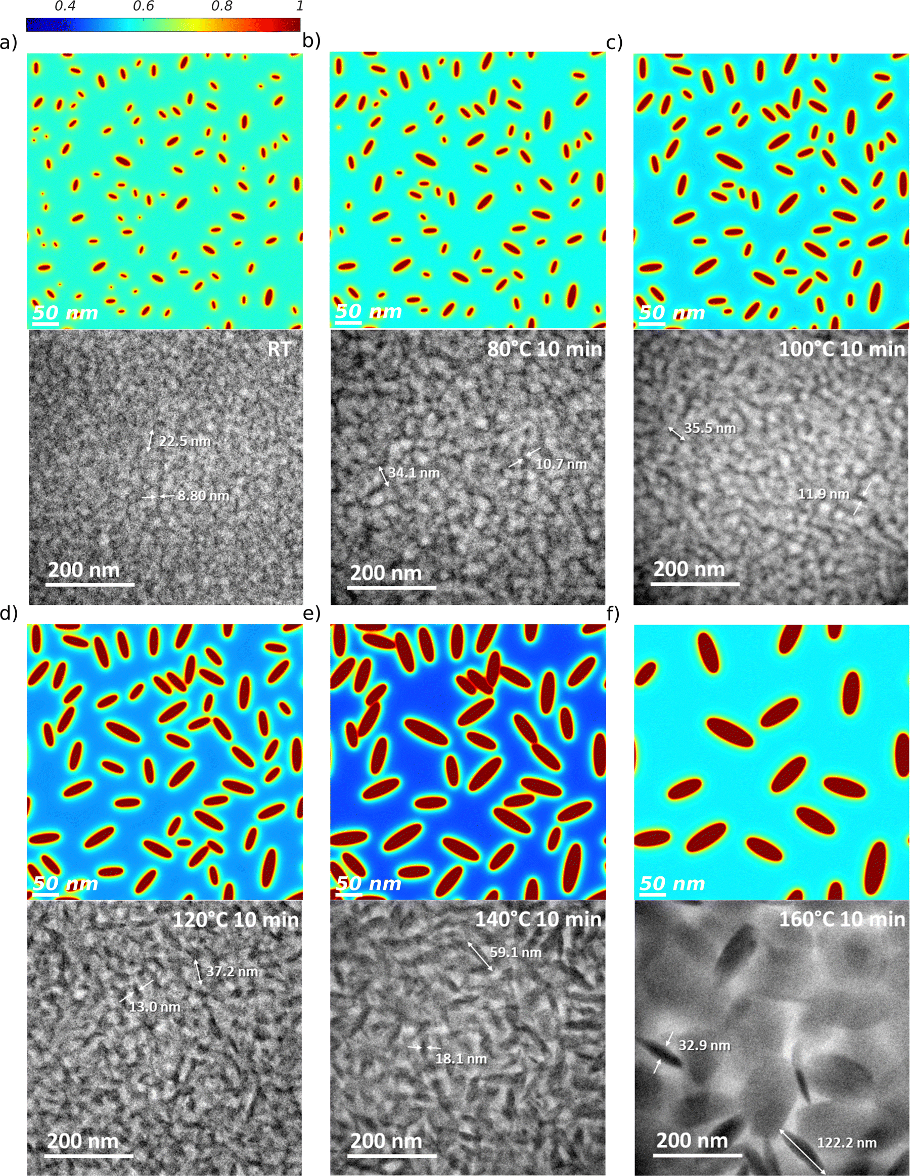 | ||
| Fig. 3 TA of a binary DRCN5T:PC71BM blend with an initial blend ratio of 1:0.8, simulation of type A. The DRCN5T volume fraction fields versus EFTEM images (reproduced with permission from ref. 21 CC BY 4.0) obtained are shown for the as-cast film with low crystal density (a) and after 600 s at TA temperatures of 80 °C (b), 100 °C (c), 120 °C (d), 140 °C (e), and 160 °C (f). The volume fraction colorbar spreads from dark blue (low DRCN5T content) to dark red (pure DRCN5T). The EFTEM images are elemental maps of carbon, the grayscale of the phase's density spreads from light grey (carbon-rich phase, PC71BM) to dark (carbon-poor phase, DRCN5T). The large platelets are assigned to face-on crystals (not considered in the simulations) whereas the more pronounced fibers correspond to edge-on crystals. | ||
Moreover, like in the experimental observations, the higher the temperature, the fewer crystals are observed in the final morphology (see also Fig. 4). This is due to the increasing critical radius with temperature (see Section 2). At all TA temperatures, it has been checked that crystals dissolve whenever they are smaller than the critical size (see Section S6 in the ESI†). In addition, note that the volume fraction of DRCN5T in the amorphous phase after 10 min of TA varies with temperature, decreasing from 80 °C to 140 °C, and increasing again for 160 °C. This is a purely kinetic effect: crystallization is not complete after 10 min and thus the equilibrium volume fraction of the amorphous phase (which is fairly constant in the range 80–160 °C, see Fig. S4, ESI†) is not reached yet. The time-dependent DRCN5T amount in the amorphous phase is the result of the (nearly negligible) initial DRCN5T release from unstable germ dissolution, and mainly of DRCN5T consumption for crystal growth. DRCN5T consumption is faster for higher temperatures, but the number of stable crystals taking up materials decreases with temperature. The balance of both results in a maximum uptake from the amorphous phase at intermediate temperatures (140 °C, see Fig. 4).
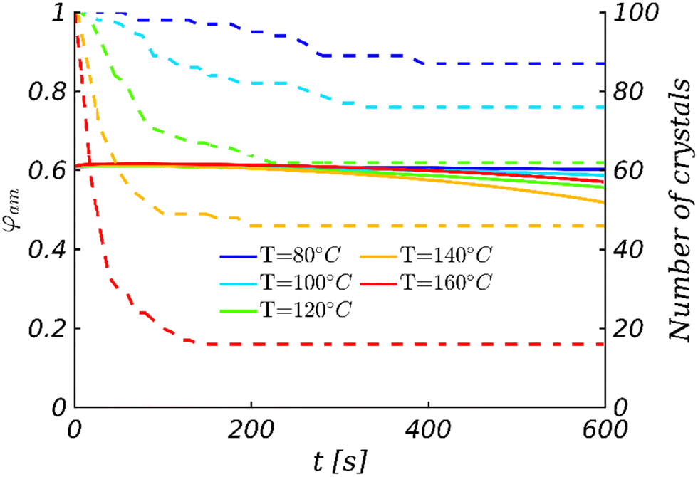 | ||
| Fig. 4 Time-dependent DRCN5T volume fraction in the amorphous phase φam (solid line and left y-axis) and the number of DRCN5T crystals (dashed line and right y-axis) for different annealing temperatures. | ||
Note that the DRCN5T volume fraction decrease in the liquid phase is additionally responsible for an increase in the critical radius with time. However, we verified that this volume fraction decrease does not result in further crystal dissolution, as shown in Fig. 4. The change in the number of crystals and the change in the DRCN5T volume fraction in the amorphous phase φam are actually uncorrelated. At 120 °C for instance, the crystals dissolve until 200 s of TA due to the initial temperature rise, whereby the DRCN5T volume fraction is constant during this phase. Afterwards, the DRCN5T volume fraction decreases, which indeed leads to an increase of the critical size. However, the remaining crystals grow sufficiently fast for their size always remains larger than the critical size, and therefore the number of crystals remains constant. Such a behaviour is observed for all other TA temperatures.
In the simulations presented above, the evolution towards a smaller number of larger crystals upon TA is due to initial dissolution of the smaller crystals due to thermal instability, and growth of the remaining, stable crystals. Ostwald ripening, which is by definition a process leading to the disappearance of smaller crystals and size increase of the larger ones, could also be invoked to justify the experimental morphologies. However, in the simulations, it is negligible. This is because Ostwald ripening becomes dominant only at late stages of the crystallization process. The evolution of the morphology is driven by the free energy minimization of the system. This actually starts with the minimization of the bulk energy due to crystal growth. Ostwald ripening, which is driven by the reduction of crystal interfacial energy, only becomes dominant once the bulk energy does not nearly change anymore (equilibrium compositions are nearly reached in the amorphous and crystalline phases). However, the equilibrium volume fractions are far from being reached at the end of the annealing (see Fig. 4), so the growth process fully masks the consequences of Ostwald ripening.
Nevertheless, these findings assume that the DRCN5T volume fraction in the amorphous phase of the as-cast film, at the beginning of the TA, is far above the equilibrium value. However, this is actually unknown experimentally. If one assumes an initial DRCN5T volume fraction equal or close to the equilibrium volume fraction, crystal growth would be only shortly active and Ostwald ripening would become quickly dominant. However, in such conditions, the average crystal size would follow a time evolution proportional to the cubic root of time or even slower,23,50–52 whereas it increases linearly with time in the case of crystal growth (see Fig. 5). Experimental evaluation showed that in the case of TA, the average DRCN5T crystal size evolves linearly with time.8 This finding supports the idea that Ostwald ripening is not significant during TA of DRCN5T:PC71BM.
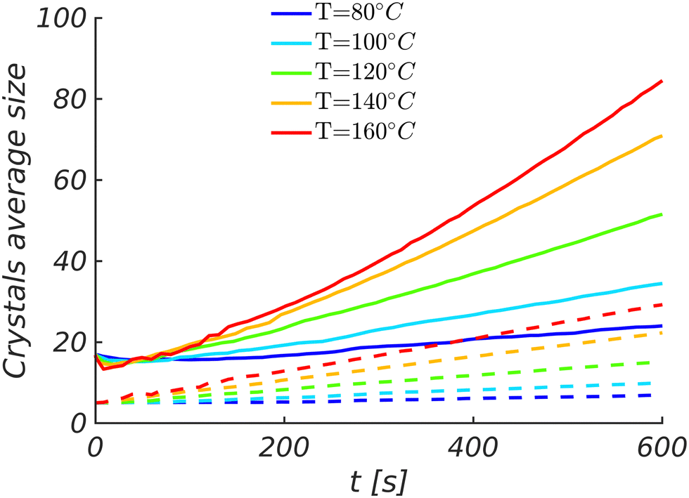 | ||
| Fig. 5 Time evolution of the average crystal lengths (solid lines) and widths (dashed lines) for different annealing temperatures. | ||
Overall, the matching between morphologies resulting from simulations of type A and the experimental observations allows us to conclude that the morphology evolution of the as-cast DRCN5T:PC71BM blends during TA is mainly driven by the dissolution of initially too small, unstable germs and the subsequent growth of the remaining large, stable DRCN5T crystals.
3.2. Crystal impingement
As shown in Fig. 3b–f, at 10 min of TA, the leaf shape of the crystals is conserved at all annealing temperatures. This is because the density of growing crystals is too low for the crystals to impinge within 10 min of TA. However, the crystal density of the as-cast film was not determined experimentally.8 In simulations of type B, the initial crystals density is increased, which increases the chance for crystals to impinge. The objective is to determine whether the presence of impingement can still lead to BHJ morphologies similar to the experimental observations in Section 2.1. This will allow us to conclude whether crystals impingement is significantly active during the thermal annealing of the DRCN5T:PC71BM active layer. Wherever impingement is happening, crystal growth is hindered at the crystal–crystal boundaries. As compared to simulations of type A, this results in a significant deviation of the crystal shape from the leaf shape for the impinged crystals at the contact points where growth is hindered, as shown in Fig. 6d–f for TA temperatures above 120 °C. This is not in line with the experimentally observed morphologies, which support the idea that the density of growing crystals during TA is too low for the crystals to impinge significantly. The mismatch between morphologies resulting from simulations of type B and the experimental observations allows us to conclude that crystal impingement is not significantly active during the 10 min of TA of the DRCN5T:PC71BM active layer. | ||
| Fig. 6 TA of a binary DRCN5T:PC71BM blend with an initial blend ratio of 1:0.8, simulation of type B. The DRCN5T volume fraction fields are shown for the as-cast film with high crystal density (a) and after 600 s at TA temperatures of 80 °C (b), 100 °C (c), 120 °C (d), 140 °C (e), and 160 °C (f). The volume fraction colorbar spreads from dark blue (low DRCN5T content) to dark red (pure DRCN5T). | ||
3.3. Nucleation and grain coarsening
The effect of nucleation and grain coarsening (i.e. the growth of largest crystals at the expense of the smallest ones driven by the minimization of grain boundary energy) is investigated through simulations of type C, whereby thermal fluctuations are activated. A comparison of the experimental observations in Section 2.1 with morphologies influenced by nucleation and coarsening will allow us to conclude whether both processes are significantly active during the thermal annealing of the DRCN5T:PC71BM active layer. First of all, the morphology evolution at the lowest annealing temperature (80 °C) is investigated (Fig. 7, top row), for which the largest nucleation rate (see Section S3 in the ESI†) and the lowest growth rate (see Section S5 in the ESI†) are expected. The morphology is very different as compared to simulations of type A. On the one hand, the number of crystals after 150 s to 600 s of TA (Fig. 7, top row) is considerably increased due to nucleation, unlike the observations from the experiments.8,21 The growth of these many crystals leads to a quick decrease of the DRCN5T content in the amorphous phase. On the other hand, the nucleation process favours the development of morphologies with clustered crystals and large-scale phase separation, which can be explained in three main steps. The first step is the favoured DRCN5T germ nucleation at the existing crystals interface where the DRCN5T volume fraction is high (Fig. 7a and b). The second step is the formation of amorphous phase bridges with high DRCN5T content between the germs favoured by the limitation of the energetic cost associated with amorphous–crystalline interfaces. The third step is the further nucleation within the formed amorphous bridges, because the critical germ size is smaller and the driving force of crystallization is larger for higher DRCN5T content.27 This large scale co-continuous morphology favours crystal impingement. Here again, this leads to ill-defined crystal shapes, as observed in Fig. 7c. At higher temperatures (for example 140 °C, Fig. 7, bottom row), nucleation is less intense, and growth is faster, so that the evolution is more growth dominated. There are less but larger crystals growing in the BHJ than at lower temperatures. As a result, the observations made at 80 °C regarding the number of crystals, crystal impingement and clustering, and large-scale phase separation are less pronounced, but they are still valid. Thus, the nucleation process generates morphological features that are not observed experimentally, and we conclude that nucleation is not significantly active during TA of the studied system. | ||
| Fig. 7 TA at 80 °C (top row) and 140 °C (bottom row) of a binary DRCN5T:PC71BM blend with an initial blend ratio of 1:0.8, simulation of type C. The DRCN5T volume fraction fields are shown, after TA of 150 s (a) and (d), 300 s (b) and (e), and 600 s (c) and (f). The volume fraction colorbar spreads from dark blue (low DRCN5T content) to dark red (pure DRCN5T). | ||
Similar to Ostwald ripening, grain coarsening becomes dominant when the equilibrium volume fraction is reached in the amorphous phase. This occurs at very late stages (note that at both annealing temperatures the DRCN5T volume fraction in the amorphous phase still decreases with time until 600 s) and explains why it is a secondary process during the 10 min of TA of the DRCN5T:PC71BM film. The influence of coarsening can be evaluated by counting the number of stable crystals that disappear upon coarsening. At 140 °C for instance, it is observed that crystal dissolution due to coarsening only occurs starting from 250 s of TA (see Section S7 in the ESI†). At the end of the TA (600 s), only 15–20% of the crystals have disappeared due to coarsening. The impact of the coarsening is, therefore, very limited overall and cannot justify the strong reduction in the number of crystals experimentally observed at high TA temperatures.
Overall, the mismatch between morphologies resulting from simulations of type C and the experimental observations allow us to conclude that nucleation and grain coarsening are not significantly active during the 10 min of TA of the DRCN5T:PC71BM active layer.
3.4. Amorphous–amorphous phase separation
AAPS is another possible physical phenomenon for the morphology evolution of the DRCN5T:PC71BM film. In this section, we trigger AAPS by choosing a value of χaa above the critical value (simulations of type D). The objective is to determine whether BHJ in which AAPS takes place have morphologies in line with the experimental observations of Section 2.1. This will allow us to conclude whether AAPS is active during the thermal annealing of the DRCN5T:PC71BM active layer. The morphology at a TA temperature of 80 °C is shown in Fig. 8. As a result of donor–acceptor immiscibility, the amorphous phase demixes into a donor and an acceptor amorphous phase. As a result, there are 3 phases in the BHJ (Fig. 8b). The first phase is the very pure crystalline DRCN5T material, the second is the amorphous PC71BM-rich phase, and the third one is the amorphous DRCN5T-rich phase (see Section S8 in the ESI†). However, in the EFTEM image, there are only 2 phases at the final stage of the TA: the amorphous mixed phase and the crystalline DRCN5T material. The mismatch between simulations of type D and the experimental observations allows concluding that AAPS is not triggered during TA of the DRCN5T:PC71BM active layer. | ||
| Fig. 8 TA at 80 °C of a binary DRCN5T:PC71BM blend with an initial blend ratio of 1:0.8, simulation of type D. The DRCN5T volume fraction fields are shown for the as-cast film with low crystals density (a) and at a TA time of 600 s (b). The volume fraction colorbar spreads from dark blue (low DRCN5T content) to dark red (pure DRCN5T). | ||
3.5. Diffusion-limited crystal growth
The remaining question to be answered is whether crystal growth is diffusion-limited during the TA of the studied all small-molecule system. To this end, simulations with diffusion-limited crystal growth (type E) are performed and the resulting morphologies compared to the experimental observations of Section 2.1. The morphologies after 10 min of TA at temperatures of 80 °C, 100 °C, 120 °C, 140 °C and 160 °C are shown in Fig. 9. Provided the growth process is sufficiently fast and advanced (120 °C and beyond), depletion zones characteristic of the diffusion-limited regime form around the DRCN5T crystals (Fig. 9c–f). The DRCN5T volume fraction in the depletion zones becomes lower at higher temperatures. This is due to the larger and faster crystal growth with increasing temperature. Notably, the leaf shape of the DRCN5T crystals is well conserved. Apart from the thin depletion areas around the crystals, the morphologies are similar to those observed without diffusion limitation (compare with Fig. 3). Experimentally, the question of the presence of depletion zones around the DRCN5T crystals during the TA remains difficult to solve, even though Wu and coworkers have identified an enrichment of PC71BM around the DRCN5T crystals using 4D scanning confocal electron diffraction (4D-SCED) for a TA of 8 min at 140 °C.21 On the one hand, this means that the occurrence of diffusion limitations during crystal growth cannot be fully confirmed or discarded on the basis of the comparison between simulation results (type A and E) and the experimental observations. On the other hand, this shows that the influence of diffusion limitations on morphology is anyway very limited, which means that diffusion limitations do not represent a decisive driver for morphology development. | ||
| Fig. 9 TA of a binary DRCN5T:PC71BM blend with an initial blend ratio of 1:0.8, simulation of type E. The DRCN5T volume fraction fields are shown for the as-cast film with low crystal density (a) and after 600 s at TA temperatures of 80 °C (b), 100 °C (c), 120 °C (d), 140 °C (e), and 160 °C (f). The crystal growth is diffusion-limited. The volume fraction colorbar spreads from dark blue (low DRCN5T content) to dark red (pure DRCN5T). | ||
4. Conclusions and outlook
We applied a phase field model to simulate the TA of a DRCN5T:PC71BM film, mimicking the experiments conducted in ref. 8 and 21. The model parameters were adjusted based on the experimental values published for the DRCN5T:PC71BM system. Physics-based temperature dependencies were used for the material parameters. The objective was to determine which physical processes are the main drivers of the BHJ morphology evolution under TA. From the comparison of the simulation results with experimental data,8 we conclude that the morphology evolution during TA is mainly driven by (1) the early dissolution of the smallest as-cast crystals that become thermodynamically unstable at higher temperatures and (2) the growth of the remaining large crystals fed by the small molecules available in the amorphous matrix. The simulation results do not provide any conclusive answer regarding a diffusion-limited regime during crystal growth, since it only has a very limited qualitative impact on the morphology. All other possible physical processes investigated in this work (AAPS, nucleation, crystal impingement, grain coarsening, Ostwald ripening) can be considered inactive or negligible. Impingement, as a physical phenomenon leading to crystals deviating from the initial leaf shape, remains untriggered in the present case. AAPS would result in the formation of a three-phase morphology, which is not observed in the measurements. Nucleation would increase the number of crystals upon annealing, which is clearly not observed either. Ostwald ripening and grain coarsening are late-stage processes that are not involved in the early crystal dissolution and hardly influence the late morphology evolution within the investigated TA times. Table 3 summarizes these conclusions on the various considered physical processes.| Phenomenon | BHJ morphology evolution driver? |
|---|---|
| Crystal nucleation | No |
| Grain coarsening | No |
| Impingement | No |
| AAPS | No |
| Diffusion limitation | Not conclusive |
| Growth of large crystals | Yes |
| Instability of small crystals | Yes |
| Ostwald ripening | No |
SVA treatments were also carried out on the same DRCN5T:PC71BM samples,8 which led to PCEs comparable to the one obtained with TA. Furthermore, the SIMS measurements realized by Min and coworkers on SVA and TA show a significant microstructure evolution in the SVA morphology after aging,18,20 as well as a drop in PCE. In the future, the phase field approach presented here for the investigation of TA can also be used to understand the morphology evolution after SVA. More generally, it can be applied to understand the formation of the BHJ morphology upon processing and its stability upon thermal loading. Moreover, further studies on the morphology–performance relationship will allow investigation into how the efficiency and the intrinsic stability of OSCs depend on the BHJ morphology, and therefore on the fabrication procedures.
Data availability
The simulation data used for this article is publicly accessible (see DOI: https://zenodo.org/doi/10.5281/zenodo.14267943).Conflicts of interest
There are no conflicts to declare.Acknowledgements
The authors acknowledge financial support from the German Research Foundation (DFG, Project HA 4382/14-1 and SFB 953), the European Commission (H2020 Program, Project 101008701/EMERGE), and the Helmholtz Association (SolarTAP Innovation Platform).References
- NREL, Best Research-Cell Efficiency Chart 2022, Best Research-Cell Efficiency Chart, https://www.nrel.gov/pv/cell-efficiency.html, accessed 2022-04-25.
- M. Riede, D. Spoltore and K. Leo, Organic Solar Cells—The Path to Commercial Success, Adv. Energy Mater., 2021, 11(1), 2002653, DOI:10.1002/aenm.202002653.
- B. Kan, M. Li, Q. Zhang, F. Liu, X. Wan, Y. Wang, W. Ni, G. Long, X. Yang, H. Feng, Y. Zuo, M. Zhang, F. Huang, Y. Cao, T. P. Russell and Y. Chen, A Series of Simple Oligomer-like Small Molecules Based on Oligothiophenes for Solution-Processed Solar Cells with High Efficiency, J. Am. Chem. Soc., 2015, 137(11), 3886–3893, DOI:10.1021/jacs.5b00305.
- H. Gao, Y. Sun, L. Meng, C. Han, X. Wan and Y. Chen, Recent Progress in All-Small-Molecule Organic Solar Cells, Small, 2023, 19(3), 2205594, DOI:10.1002/smll.202205594.
- L. Zhu, M. Zhang, J. Xu, C. Li, J. Yan, G. Zhou, W. Zhong, T. Hao, J. Song, X. Xue, Z. Zhou, R. Zeng, H. Zhu, C.-C. Chen, R. C. I. MacKenzie, Y. Zou, J. Nelson, Y. Zhang, Y. Sun and F. Liu, Single-Junction Organic Solar Cells with over 19% Efficiency Enabled by a Refined Double-Fibril Network Morphology, Nat. Mater., 2022, 21(6), 656–663, DOI:10.1038/s41563-022-01244-y.
- X. Sun, J. Lv, C. Zhang, K. Wang, C. Yang, H. Hu and X. Ouyang, Morphology Controlling of All-Small-Molecule Organic Solar Cells: From Donor Material Design to Device Engineering, Sol. RRL, 2023, 7(16), 2300332, DOI:10.1002/solr.202300332.
- Z. Wang, L. Zhu, Z. Shuai and Z. Wei, A–π–D–π–A Electron-Donating Small Molecules for Solution-Processed Organic Solar Cells: A Review, Macromol. Rapid Commun., 2017, 38(22), 1700470, DOI:10.1002/marc.201700470.
- C. Harreiss, Microscopic Study on the Nanomorphology, Crystallinity, Texture and Efficiency of Organic Solar Cells, Friedrich-Alexander-Universität Erlangen-Nürnberg (FAU), 2022, https://opus4.kobv.de/opus4-fau/frontdoor/index/index/docId/18604 Search PubMed.
- M. Berlinghof, S. Langner, C. Harreiß, E. M. Schmidt, R. Siris, F. Bertram, C. Shen, J. Will, T. Schindler, A. Prihoda, S. Rechberger, G. S. Duesberg, R. B. Neder, E. Spiecker, C. J. Brabec and T. Unruh, Crystal-Structure of Active Layers of Small Molecule Organic Photovoltaics before and after Solvent Vapor Annealing, Z. Kristallogr. – Cryst. Mater., 2020, 235(1–2), 15–28, DOI:10.1515/zkri-2019-0055.
- W. Ni, X. Wan, M. Li, Y. Wang and Y. Chen, A–D–A Small Molecules for Solution-Processed Organic Photovoltaic Cells, Chem. Commun., 2015, 51(24), 4936–4950, 10.1039/C4CC09758K.
- S. Rafique, S. M. Abdullah, K. Sulaiman and M. Iwamoto, Fundamentals of Bulk Heterojunction Organic Solar Cells: An Overview of Stability/Degradation Issues and Strategies for Improvement, Renewable Sustainable Energy Rev., 2018, 84, 43–53, DOI:10.1016/j.rser.2017.12.008.
- O. Wodo and B. Ganapathysubramanian, Modeling Morphology Evolution during Solvent-Based Fabrication of Organic Solar Cells, Comput. Mater. Sci., 2012, 55, 113–126, DOI:10.1016/j.commatsci.2011.12.012.
- L. Sun, Y. Chen, M. Sun and Y. Zheng, Organic Solar Cells: Physical Principle and Recent Advances, Chem. – Asian J., 2023, 18(5), e202300006, DOI:10.1002/asia.202300006.
- O. Wodo, S. Tirthapura, S. Chaudhary and B. Ganapathysubramanian, A Graph-Based Formulation for Computational Characterization of Bulk Heterojunction Morphology, Org. Electron., 2012, 13(6), 1105–1113, DOI:10.1016/j.orgel.2012.03.007.
- O. Wodo, J. D. Roehling, A. J. Moulé and B. Ganapathysubramanian, Quantifying Organic Solar Cell Morphology: A Computational Study of Three-Dimensional Maps, Energy Environ. Sci., 2013, 6(10), 3060, 10.1039/c3ee41224e.
- A. Wadsworth, Z. Hamid, J. Kosco, N. Gasparini and I. McCulloch, The Bulk Heterojunction in Organic Photovoltaic, Photodetector, and Photocatalytic Applications, Adv. Mater., 2020, 32(38), 2001763, DOI:10.1002/adma.202001763.
- J. Min, X. Jiao, V. Sgobba, B. Kan, T. Heumüller, S. Rechberger, E. Spiecker, D. M. Guldi, X. Wan, Y. Chen, H. Ade and C. J. Brabec, High Efficiency and Stability Small Molecule Solar Cells Developed by Bulk Microstructure Fine-Tuning, Nano Energy, 2016, 28, 241–249, DOI:10.1016/j.nanoen.2016.08.047.
- J. Min, N. S. Güldal, J. Guo, C. Fang, X. Jiao, H. Hu, T. Heumüller, H. Ade and C. J. Brabec, Gaining Further Insight into the Effects of Thermal Annealing and Solvent Vapor Annealing on Time Morphological Development and Degradation in Small Molecule Solar Cells, J. Mater. Chem. A, 2017, 5(34), 18101–18110, 10.1039/C7TA04769J.
- C. Harreiß, S. Langner, M. Berlinghof, S. Rechberger, J. Will, T. Unruh, C. J. Brabec and E. Spiecker, In Situ and Ex Situ Energy-Filtered Transmission Electron Microscopy Studies on the Nanomorpholgy Evolution of Organic Bulk Heterojunction Solar Cells, Microsc. Microanal., 2019, 25(S2), 2092–2093, DOI:10.1017/S143192761901119X.
- C. Harreiß, S. Langner, M. Wu, M. Berlinghof, S. Rechberger, J. Will, M. Conroy, U. Bangert, T. Unruh, C. J. Brabec and E. Spiecker, Understanding and Controlling the Evolution of Nanomorphology and Crystallinity of Organic Bulk-Heterojunction Blends with Solvent Vapor Annealing, Sol. RRL, 2022, 2200127, DOI:10.1002/solr.202200127.
- M. Wu, C. Harreiß, C. Ophus, M. Johnson, R. H. Fink and E. Spiecker, Seeing Structural Evolution of Organic Molecular Nano-Crystallites Using 4D Scanning Confocal Electron Diffraction (4D-SCED), Nat. Commun., 2022, 13(1), 2911, DOI:10.1038/s41467-022-30413-5.
- L. Gránásy, G. I. Tóth, J. A. Warren, F. Podmaniczky, G. Tegze, L. Rátkai and T. Pusztai, Phase-Field Modeling of Crystal Nucleation in Undercooled Liquids – A Review, Prog. Mater. Sci., 2019, 106, 100569, DOI:10.1016/j.pmatsci.2019.05.002.
- B. König, O. J. J. Ronsin and J. Harting, Two-Dimensional Cahn–Hilliard Simulations for Coarsening Kinetics of Spinodal Decomposition in Binary Mixtures, Phys. Chem. Chem. Phys., 2021, 23(43), 24823–24833, 10.1039/D1CP03229A.
- O. J. J. Ronsin and J. Harting, Role of the Interplay between Spinodal Decomposition and Crystal Growth in the Morphological Evolution of Crystalline Bulk Heterojunctions, Energy Technol., 2020, 8(12), 1901468, DOI:10.1002/ente.201901468.
- O. J. J. Ronsin, D. Jang, H.-J. Egelhaaf, C. J. Brabec and J. Harting, A Phase-Field Model for the Evaporation of Thin Film Mixtures, Phys. Chem. Chem. Phys., 2020, 22(12), 6638–6652, 10.1039/D0CP00214C.
- O. J. J. Ronsin, D. Jang, H.-J. Egelhaaf, C. J. Brabec and J. Harting, Phase-Field Simulation of Liquid–Vapor Equilibrium and Evaporation of Fluid Mixtures, ACS Appl. Mater. Interfaces, 2021, 13(47), 55988–56003, DOI:10.1021/acsami.1c12079.
- O. J. J. Ronsin and J. Harting, Formation of Crystalline Bulk Heterojunctions in Organic Solar Cells: Insights from Phase-Field Simulations, ACS Appl. Mater. Interfaces, 2022, acsami.2c14319, DOI:10.1021/acsami.2c14319.
- R. A. Matkar and T. Kyu, Role of Crystal–Amorphous Interaction in Phase Equilibria of Crystal–Amorphous Polymer Blends, J. Phys. Chem. B, 2006, 110(25), 12728–12732, DOI:10.1021/jp061159m.
- R. A. Matkar and T. Kyu, Phase Diagrams of Binary Crystalline–Crystalline Polymer Blends, J. Phys. Chem. B, 2006, 110(32), 16059–16065, DOI:10.1021/jp062124p.
- T. Takaki, Phase-Field Modeling and Simulations of Dendrite Growth, ISIJ Int., 2014, 54(2), 437–444, DOI:10.2355/isijinternational.54.437.
- O. J. J. Ronsin and J. Harting, Phase-Field Simulations of the Morphology Formation in Evaporating Crystalline Multicomponent Films, Adv. Theory Simul., 2022, 2200286, DOI:10.1002/adts.202200286.
- M. Siber, O. J. Ronsin and J. Harting, Crystalline Morphology Formation in Phase-Field Simulations of Binary Mixtures, J. Mater. Chem. C, 2023, 11(45), 15979–15999, 10.1039/D3TC03047D.
- L.-Q. Chen and W. Yang, Computer Simulation of the Domain Dynamics of a Quenched System with a Large Number of Nonconserved Order Parameters: The Grain-Growth Kinetics, Phys. Rev. B: Condens. Matter Mater. Phys., 1994, 50(21), 15752–15756, DOI:10.1103/PhysRevB.50.15752.
- C.-S. Kim, D. M. Saylor, M. K. McDermott, D. V. Patwardhan and J. A. Warren, Modeling Solvent Evaporation during the Manufacture of Controlled Drug-Release Coatings and the Impact on Release Kinetics, J. Biomed. Mater. Res., Part B, 2009, 90B(2), 688–699, DOI:10.1002/jbm.b.31336.
- J. A. Sethian and J. Straint, Crystal Growth and Dendritic Solidification, J. Comput. Phys., 1992, 98(2), 231–253, DOI:10.1016/0021-9991(92)90140-T.
- I. Loginova, J. Ågren and G. Amberg, On the Formation of Widmanstätten Ferrite in Binary Fe–C-Phase-Field Approach, Acta Mater., 2004, 52(13), 4055–4063, DOI:10.1016/j.actamat.2004.05.033.
- G. B. McFadden, A. A. Wheeler, R. J. Braun, S. R. Coriell and R. F. Sekerka, Phase-Field Models for Anisotropic Interfaces, Phys. Rev. E: Stat. Phys., Plasmas, Fluids, Relat. Interdiscip. Top., 1993, 48(3), 2016–2024, DOI:10.1103/PhysRevE.48.2016.
- O. J. J. Ronsin and J. Harting, Strict Equivalence between Maxwell–Stefan and Fast-Mode Theory for Multicomponent Polymer Mixtures, Macromolecules, 2019, 52(15), 6035–6044, DOI:10.1021/acs.macromol.9b01220.
- A. Z. Akcasu, The “Fast” and “Slow” Mode Theories of Interdiffusion in Polymer Mixtures: Resolution of a Controversy, Macromol. Theory Simul., 1997, 6(4), 679–702, DOI:10.1002/mats.1997.040060401.
- S. Qiu, M. Majewski, L. Dong, D. Jang, V. M. L. Corre, J. G. Cerrillo, O. J. J. Ronsin, F. Yang, F. Guo, K. Zhang, L. Lüer, J. Harting, T. Du, C. J. Brabec and H.-J. Egelhaaf, In Situ Probing the Crystallization Kinetics in Gas-Quenching-Assisted Coating of Perovskite Films, Adv. Energy Mater., 2024, 2303210, DOI:10.1002/aenm.202303210.
- PCBM, PCBM, https://www.ossila.com/en-eu/products/pcbm.
- G. Paternò, A. J. Warren, J. Spencer, G. Evans, V. G. Sakai, J. Blumberger and F. Cacialli, Micro-Focused X-Ray Diffraction Characterization of High-Quality [6,6]-Phenyl-C61-Butyric Acid Methyl Ester Single Crystals without Solvent Impurities, J. Mater. Chem. C, 2013, 1(36), 5619, 10.1039/c3tc31075b.
- L. Zhang, N. Yi, W. Zhou, Z. Yu, F. Liu and Y. Chen, Miscibility Tuning for Optimizing Phase Separation and Vertical Distribution toward Highly Efficient Organic Solar Cells, Adv. Sci., 2019, 6(15), 1900565, DOI:10.1002/advs.201900565.
- DRCN5T, https://www.ossila.com/en-eu/products/drcn5t.
- R. Evans, G. Dal Poggetto, M. Nilsson and G. A. Morris, Improving the Interpretation of Small Molecule Diffusion Coefficients, Anal. Chem., 2018, 90(6), 3987–3994, DOI:10.1021/acs.analchem.7b05032.
- M. Rubinstein and R. H. Colby, Polymer Physics, Oxford University Press, Oxford, New York, 2003 Search PubMed.
- D. M. Saylor, C.-S. Kim, D. V. Patwardhan and J. A. Warren, Diffuse-Interface Theory for Structure Formation and Release Behavior in Controlled Drug Release Systems, Acta Biomater., 2007, 3(6), 851–864, DOI:10.1016/j.actbio.2007.03.011.
- Y. Sun, F. Zhang, H. Song, M. I. Mendelev, C.-Z. Wang and K.-M. Ho, Temperature Dependence of the Solid-Liquid Interface Free Energy of Ni and Al from Molecular Dynamics Simulation of Nucleation, J. Chem. Phys., 2018, 149(17), 174501, DOI:10.1063/1.5048781.
- B. B. Laird and R. L. Davidchack, Direct Calculation of the Crystal–Melt Interfacial Free Energy via Molecular Dynamics Computer Simulation, J. Phys. Chem. B, 2005, 109(38), 17802–17812, DOI:10.1021/jp0530754.
- A. J. Wagner and J. M. Yeomans, Breakdown of Scale Invariance in the Coarsening of Phase-Separating Binary Fluids, Phys. Rev. Lett., 1998, 80(7), 1429–1432, DOI:10.1103/PhysRevLett.80.1429.
- G. Bernard-Granger, R. L. Yeckley and R. L’Amoulen, Densification and Grain Growth Kinetic for Silicon Nitride, Key Eng. Mater., 1997, 132–136, 892–895, DOI:10.4028/www.scientific.net/KEM.132-136.892.
- J. T. Cabral, J. S. Higgins, N. A. Yerina and S. N. Magonov, Topography of Phase-Separated Critical and Off-Critical Polymer Mixtures, Macromolecules, 2002, 35(5), 1941–1950, DOI:10.1021/ma0114990.
Footnote |
| † Electronic supplementary information (ESI) available. See DOI: https://doi.org/10.1039/d4cp03486d |
| This journal is © the Owner Societies 2025 |