
 Open Access Article
 This Open Access Article is licensed under a Creative Commons Attribution-Non Commercial 3.0 Unported Licence
SR-based μXRD–μXRF 2D mapping to study Mg-rich historical frescoes subjected to inorganic conservation treatments
Elena
Possenti
 *a,
Costanza
Miliani
b,
Marine
Cotte
cd,
Marco
Realini
a and
Chiara
Colombo
a
*a,
Costanza
Miliani
b,
Marine
Cotte
cd,
Marco
Realini
a and
Chiara
Colombo
a
aInstitute of Heritage Science – National Research Council, ISPC-CNR, Via Roberto Cozzi 53, 20125, Milano, Italy. E-mail: elena.possenti@cnr.it
bInstitute of Heritage Science – National Research Council, ISPC-CNR, Via Cardinale Guglielmo Sanfelice 8, 80134, Napoli, Italy
cEuropean Synchrotron Radiation Facility, 71 Avenue des Martyrs, 38000 Grenoble, France
dSorbonne Université, CNRS, Laboratoire d'archeologie moleculaire et structurale, LAMS, F-75005 Paris, France
First published on 11th March 2025
Abstract
This paper proposes the novel application of synchrotron radiation (SR) micro X-ray diffraction (μXRD) and micro X-ray fluorescence (μXRF) mapping to explore the interaction of inorganic-mineral conservation treatments (ammonium oxalate, AmOx) with the decayed, magnesium-containing, layered carbonatic matrix of Cultural Heritage (CH) fresco paintings. The high quality of SR μXRD–μXRF datasets was qualitatively and semi-quantitatively investigated and the complex mixture and stratigraphy of both Ca- and Mg-oxalate phases formed within an Italian fresco painting (XV century) – displaying a high degree of compositional and microstructural heterogeneity – were 2D localised at the microscale. The comparison of the different phase maps and elemental maps showed how the phase composition of reaction products varies as a function of the (i) Mg-rich or Ca-rich carbonatic regions of the fresco, (ii) Ca2+ availability, and (iii) microstructure and state of conservation of the fresco. Moreover, the crystallisation of the new phases within single layers and between contiguous ones of the fresco painting was highlighted, demonstrating the synergic protective, passivating, and consolidating action of AmOx treatment across the fresco stratigraphy. Above all, this study proves the high potential of SR μXRD–μXRF mapping in the conservation of stone materials and opens new analytical perspectives in heritage science and materials science for the advanced and non-destructive elemental and structural investigations of heterogeneous, layered, multiphase micrometric systems.
Introduction
Synchrotron radiation (SR) micro X-ray diffraction (μXRD) and micro X-ray fluorescence (μXRF) mapping are advanced analytical techniques that provide non-destructive insights into the composition and structure of materials.1–5SR μXRD mapping enables identifying and spatially localizing crystalline phases within complex mixtures, facilitating the qualitative and quantitative structural characterisation of compounds in polycrystalline materials at a microscopic level. Complementing this, SR μXRF mapping generates elemental information at the microscale, providing a detailed characterization of the distribution of marker elements within an investigated region of interest (ROI). In addition, many SR facilities are currently implementing the experimental setup of X-ray microprobe beamlines to improve the top spatial resolution achievable during the experiments.
The synergy of these powerful techniques and the advantages provided by synchrotron sources (high beam brightness, energy tunability, improved small probing, up-to-date technological hardware and software facilities and high flexibility of the beamline setup) are particularly relevant in the study of micro-fragments from cultural heritage (CH), where the need for obtaining the maximum amount of information from unique and small amounts of complex materials faces the analytical challenges of finding non-destructive approaches providing, at the same time, high phase sensitivity, minor and trace phase analysis, and mapping capabilities.
In heritage science, the analysis and conservation of paint stratigraphies stand as crucial areas of research. This research field deals with a challenging analytical scenario due to the heterogeneous nature of the matrixes under investigation. Indeed, these matrixes are characterised by high complexity, in terms of composition (i.e. being polycrystalline due to the co-existence of pigments, fillers, binders, etc.) and microstructure (i.e. wide grain size distribution; point-by-point variations of layer cohesion and layer thickness). Additionally, they consist of micrometric, multi-layered systems. In this research field, the application of a multimodal μXRD–μXRF mapping approach using synchrotron radiation is gaining increasing attention as demonstrated by the growing number of recent publications on CH materials and on paint materials in particular.1,6–14 Within this scenario, recent studies applied the high potential of SR μXRD–μXRF mapping to study the stone materials of CH (both natural and artificial), in terms of mineralogical composition, decay processes and conservation protocols.1,13,15–17
The paint stratigraphies of wall paintings and frescoes are characterised by pigments and fillers dispersed in a carbonatic lime binder. When these matrixes decay due to environmental factors, they can experience various deterioration patterns such as decohesion, powdering, flaking, lifting and cracking of surface layers and loss of colour due to rainwater leaching. Additionally, loss of adhesion to the support or between contiguous paint layers may occur. An effective conservation practice involves applying inorganic-mineral treatments to restore the microstructural cohesion of the carbonatic paint surface and therefore to avoid the material loss.18,19 In particular, ammonium oxalate (denoted as “AmOx”, (NH4)2C2O4) is one of the widely used products for the conservation of mural paintings and frescoes. AmOx inorganic-mineral treatments are performed by applying AmOx aqueous solutions that diffuse by capillarity inside the pores of the substrate and react with the substrate, inducing a partial transformation of the minerals of the original matrix into newly formed phases that are able to restore the lost cohesion of the microstructure.
Thus far, a substantial part of scientific investigations on the subject has focused mainly on the interaction of AmOx with calcium carbonate (calcite, denoted as “Cal”, CaCO3),15,20 but a few studies are focused on the reaction of AmOx with other carbonates, such as magnesium-containing carbonates. Within this scenario, it has been demonstrated that the oxalate ions of the treatment react with the Ca2+ ions of Cal (either of natural or artificial substrates) to promote the formation of distinct calcium oxalates: whewellite (denoted as “Whe”, CaC2O4·H2O), weddellite (denoted as “Wed”, CaC2O4·(2 + x)H2O), or a mixture of them.5,15,20–24 The two calcium oxalates are characterised by different levels of phase stability, with Whe being a highly stable phase and Wed an unstable one. Moreover, they may be localised in different regions of the treated materials depending on several reaction conditions (availability of calcium ions, pH of the reaction, the presence of soluble salts, and decay of the substrate).15,20,25,26 In this view, it has been shown how the 2D/3D phase distribution and penetration depth of reaction products vary as a function of the kinetics of the reaction and treatment modality.5,15,20,21,25,27–29 What's more, these studies strongly pointed out the need to push forward the crystallochemical characterisation of novel products formed within the CH substrates as well as to explore the possible chemical interactions taking place with the minerals of the substrate beyond those of the binder, such as with aggregates, pigments, and the possible decay products.8,14,29 The examination of the interaction between AmOx and pigments holds particular significance due to the vulnerability of certain pigments to the ammonia released during AmOx treatments. While this undesired side effect is partially known in the context of AmOx reactions with copper-based pigments,30 there is limited knowledge regarding its impact on iron-based pigments.
An advanced and spatially localised elemental characterisation study is as important as the mineralogical-structural one. Indeed, the matrix of wall paintings and frescoes contains a lot of different elements beyond Ca, such as Mg, Fe and Si, just to cite the most frequent ones. Mg, in particular, is very common in CH carbonate matrixes, both natural (dolostones and dolomitic marbles or marbles with dolomitic veins) and artificial (Mg-limes in mural paintings and dolomitic aggregates). Its presence, even in small amounts, is found to significantly alter the formation of reaction products in the case of conservation treatments with other inorganic mineral products, such as diammonium hydrogen phosphate.31–34 However, a few are known related to the AmOx reaction with Mg ions of Mg-containing carbonate substrates.29,35,36 Moreover, no data are available (i) on the crystallisation of oxalates within the stratigraphy of Mg-containing mural paintings, (ii) on the possible AmOx interactions with the pigments in Mg-matrixes, as well as (iii) on how the crystallisation of oxalates in decayed Mg-containing stone matrixes may be affected by the presence of decay products, such as sulphates.
Given these considerations, SR μXRD–μXRF mapping has been used in this research to investigate, at the microscale, the interactions between ammonium oxalate and the heterogeneous, layered, decayed, Mg-containing matrix of CH fresco paintings.
The high potential of SR μXRD–μXRF mapping was crucial for exploring the microsamples and micro-crystals under study, thanks to the suitability of these X-ray microprobes for the application scale. Indeed, the investigations were performed on microsamples from an Italian XV century fresco exposed to outdoor conditions and treated with AmOx to explore the: (i) AmOx reaction as a function of Ca-containing and/or Mg-containing regions of the matrix, (ii) diffusion of AmOx in Mg-containing layered substrates, and therefore the crystallisation of the new phases within single layers and between contiguous ones, and (iii) possible AmOx reactions with chromophore minerals within the matrixes, such as the Fe-based pigments, and/or with other accessory minerals in the pigments, such as silicate and dolomite aggregates. Moreover, the fresco stratigraphy displayed a natural decay process, which permitted one to (iv) showcase the AmOx reaction in real-case scenarios in the presence of decay products and its action on the decayed microstructure of the fresco.
Materials and methods
Materials
The Italian XV century fresco of Povo (Trento, Italy) exposed to outdoor conditions has been selected to explore the interactions of ammonium oxalate conservation treatments with heterogeneous, layered, decayed stone matrixes of CH (Fig. 1). The study of this fresco is part of a research project aimed at evaluating and monitoring the performances and the behaviour of AmOx inorganic-mineral treatments over time on carbonatic artificial stone materials that exhibit significant crystallochemical and microstructural heterogeneity.37 | ||
| Fig. 1 (a) General overview of the Italian XV century fresco of Povo (Trento, Italy) exposed to outdoor conditions. The dashed rectangle highlights the area investigated in the study. (b) Cleaning test area with the untreated sample. (c) Details of the cleaning test area where samples S1 and S2 have been taken. (d) Optical image acquired in situ with a portable microscope of the cleaned fresco surface before AmOx conservation treatments. (e) XRD pattern of one of the micro-fragments obtained from the cleaned area before the AmOx treatments. (f) Optical image and (g) SEM image of the polished cross-section of the untreated fresco. (h and i) Optical images acquired by using a microscope in polarized light (N 45°) of the untreated fresco. On the left is an image at a lower magnification, clearly showing the darker plaster layer on the surface, which adheres closely to the underlying arriccio, characterized by several discontinuities in the mortar matrix. On the right is a detailed view of the surface plaster layer. | ||
The mineralogical composition of the fresco, the painting technique, the layer sequence as well as the state of conservation have been explored on selected micro-fragments obtained before the AmOx treatments in a cleaning test area and analysed using lab-scale instruments (scanning electron microscopy (SEM) and energy dispersive X-ray spectrometry (EDS); powder XRD of bulk powdered samples with a Cu X-ray source; optical microscopy with a polarizing petrographic microscope, Fig. 1). The previous investigations by powder XRD of the micro-fragments obtained from the cleaned area before the AmOx treatments revealed the presence of quartz, calcite, albite, K feldspar, gypsum and phyllosilicates. No calcium oxalates (and other oxalates in general) were observed in the untreated micro samples used to characterize the mineralogical composition of the fresco before applying the AmOx conservation treatment.
Then, the fresco painting was treated in situ by using poultice with a 0.28 M water-based AmOx solution (4% w/w; AmOx CAS number: 6009-70-7, assay ≥98.0%, reagent grade) for 10 hours. The poultice was applied to the fresco surface, and a layer of Japanese paper was inserted between the paper poultice and the fresco surface to prevent damage from the poultice sticking after drying (poultice ratio: ∼5![[thin space (1/6-em)]](https://www.rsc.org/images/entities/char_2009.gif) :1 AmOx solution:cellulose pulp; the poultice was approximately 1–1.5 cm thick). At the end of the conservation treatment, the surface of the fresco was rinsed by using a poultice with Milli-Q water in order to remove any metastable/soluble reaction by-products or unreacted reagents from the fresco substrate.
:1 AmOx solution:cellulose pulp; the poultice was approximately 1–1.5 cm thick). At the end of the conservation treatment, the surface of the fresco was rinsed by using a poultice with Milli-Q water in order to remove any metastable/soluble reaction by-products or unreacted reagents from the fresco substrate.
To investigate the interaction between the AmOx treatments with the minerals of the fresco, two micro-fragments (designated as sample S1 and sample S2) were collected from the treated surface in representative regions exhibiting a different state of conservation before the AmOx application. Specifically, sample S1 was collected from a decayed region exhibiting microscale disintegration, characterized by the detachment of single grains or aggregates of grains, as defined by the ICOMOS Glossary (also labelled “decohesion”38). Sample S2 was obtained from a severely decayed area of the fresco, displaying macroscale disintegration due to significant decohesion, and flaking, with the scaling in thin scales of submillimetric thickness.
An ad hoc sample preparation procedure has been developed by the TS Lab & Geoservices s.n.c, Cascina (Pisa, Italy) to obtain polished thin sections suitable for the SR μXRD–μXRF 2D mapping and to prevent any potential grain loss during the microtoming and polishing processes.1,15 The customised thin section procedure involved the initial embedding of the micro-fragments in a cold-polymerizing epoxy resin to strengthen the fragments and then they were embedded in a polyester resin specifically chosen for polishing. After curing, the resulting resin blocks were glued on a 1 mm-thick polycarbonate sheet (∼2 × 3 cm) and polished until reaching the thickness of ∼30 μm. Following this, a representative sample measuring about 1.5 × 1.5 mm was extracted from the polycarbonate thin section to fit within the μXRD–μXRF experimental sample holder.
Methods
000 (FOV: 12.80 × 9.60 μm) and 25000 (FOV: 5.120 × 3.840 μm).
X-rays were produced with an undulator and the energy was defined using a Si (111) double crystal monochromator. An unusual two-energy beam was implemented, with the fundamental excitation at 3.04 keV to achieve a good excitation of Mg and at a less intense third harmonic at 9.12 keV to have a (low) excitation of Ca and Fe. The beam size was reduced down to 0.6 μm × 0.4 μm (horizontal × vertical) using a Kirk-Patrick–Baez mirror system. The samples were mounted vertically, with an angle of 62° with respect to the beam and XRF was collected at an angle of 90° (with respect to the beam), using a silicon drift detector (RaySpec, 80 mm2 collimated active area), controlled with Xia readout electronics. Incident intensity was monitored by using a photodiode detector upstream of the sample. Analysis was carried out under vacuum, which reduces scattering effects and reabsorption of XRF by air. The Daiquiri interface was used to navigate on the samples and to define the ROIs investigated at ID21.40 The step size was 2 μm and the dwell time was 0.025 s.
The setup at ID13 was optimised for 2D lateral resolution of μXRD and μXRF maps. The energy of the incident monochromatic X-ray beam was around 13 keV (λ = 0.95753 Å). The incident synchrotron radiation beam was focused down to a beam footprint size of approximately 2.5 × 2.5 μm2 using a compound refractive lens set-up (CRL) mounted in a transfocator. The samples were mounted vertically on a motorized xyz stage, perpendicular to the beam, and they were raster scanned over a 2D map in continuous mode with a step size of 2 μm (sample S1) or 1 μm (sample S2). The area to be mapped of each sample was selected by using the newly developed user interface available, Daiquiri, initially developed for ID2140 and recently deployed to ID13. One XRD pattern and one XRF pattern were acquired for each pixel of 2D maps simultaneously.
Two dimensional diffraction patterns (Debye–Scherrer rings) were recorded by using a Dectris EIGER 4M (2070 × 2167 pixels, 75 × 75 μm2 pixel size) positioned downstream the samples. The angular step size of XRD patterns was of 0.04° over the 0.02–51.91° 2θ angular range. A 10 ms dwell time was used to collect the XRD signal, i.e. sufficient to detect the crystalline phases and, at the same time, to reduce the risk of beam damage. The 2D diffraction rings were converted into 1D diffractograms by automated azimuthal integration, carried out by using dedicated Jupyter notebooks, based on the PyFAI software package.42
XRF spectra were acquired on each pixel, over the same 2D region of the maps, using a 2 Vortex EM XRF detector and XIA readout electronics positioned behind the samples.
The same Daiquiri interface was used to navigate on the samples and to find back the same ROIs investigated at ID21.
μXRD/μXRF maps were analysed using PyMca.43 The PyMca and ROI imaging software were used to extract average XRD patterns over a selection of pixels and to generate XRD files for the qualitative and quantitative analyses. The Match! package and the X'Pert HighScore software package (PANalytical B.V., Almelo, The Netherlands, version 2.2.0) were used as well for the phase identification in XRD datasets. False colour 2D distribution maps of selected crystalline phases were then generated using PyMca and the ROI imaging tools44 by integrating peculiar diffraction angular ranges and/or marker diffraction peaks of specific crystalline phases. XRD ROIs were selected considering the peak intensity and the absence of overlapping peaks with other phases.
Both ID21 and ID13 XRF spectra were batch fitted using the PyMca software package and the 2D XRF maps of specific elements were extracted from the maps. ID13 μXRD and μXRF 2D maps were superimposed by using the RGB correlation tool of PyMca.
Results and discussion
The layer morphology and layer sequence of the fresco in the two treated samples are displayed in the optical images, the SEM images and the μXRF 2D maps shown in Fig. 2. The fresco stratigraphy was composed from the inner region by the (1) arriccio portion, (2) intonachino portion, and (3) external portion of intonachino painted with Fe-based pigments.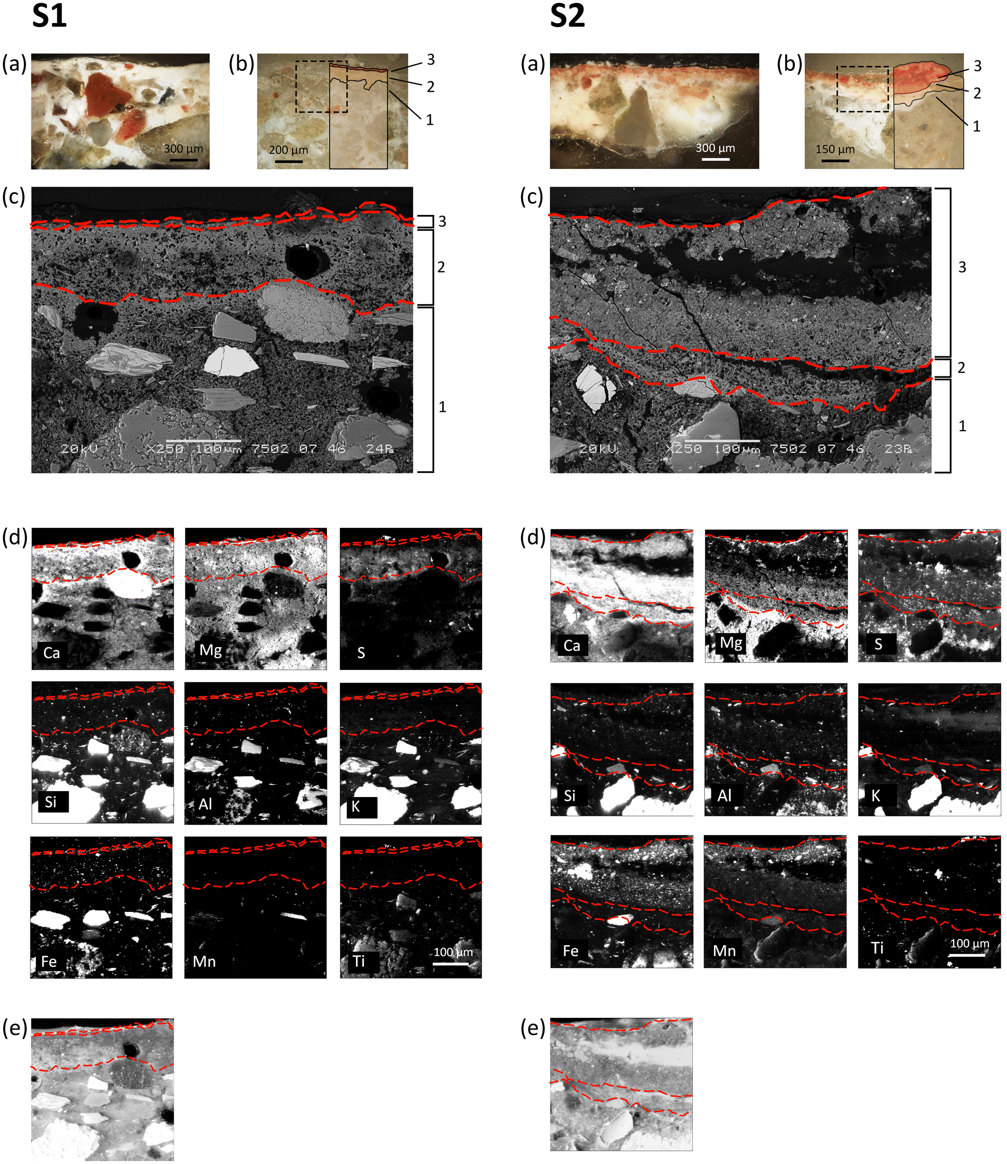 | ||
| Fig. 2 Sample S1 (on the left) and sample S2 (on the right). (a) Optical images of the polished cross-section, (b) optical images of the thin polished cross-section and (c) SEM image of the samples. (d) μXRF distribution maps collected at ID21 of calcium (Ca), magnesium (Mg), sulphur (S), silicon (Si), aluminium (Al), potassium (K), iron (Fe), manganese (Mn) and titanium (Ti), presented in a colour map spanning from low (black) to high (white) values of relative intensity. (e) Total fluorescence map. In (b–e), the dotted red lines highlight the layer sequence of the fresco in the two samples: (1) arriccio, (2) intonachino and (3) external portion of intonachino with iron-based pigments. The investigated ROI (dashed square in (b)) was of 400 × 400 μm2 horizontal × vertical (h × v) for sample S1 and of 430 × 400 μm2 (h × v) for sample S2. | ||
The optical images (Fig. 2a and b) and SEM observations (Fig. 2c) show that samples S1 and S2 exhibit differences in the layer thickness and microstructural cohesion. Indeed, the thickness of layers 2 and 3 was ∼100 μm and ∼10 μm for sample S1, respectively, and ∼80 μm and ∼150 μm for sample S2, respectively. As for the microstructural cohesion, sample S1 exhibits a quite compact microstructure without cracks, while sample S2 shows significant microstructural decohesion and the presence of micrometric cracks, which are oriented either parallel or transversal to the layer sequence. These microstructural features are also visible in the total fluorescence maps of Fig. 2e and they are consistent with the macroscopic observations conducted in situ with regard to the conservation state of different areas of the fresco surface (Fig. 1).
As shown by the SR μXRF 2D maps of Fig. 2d, in both samples S1 and S2, the arriccio (layer 1) of the fresco is made of a Ca and Mg lime binder and of Si-, Al- and K-containing coarse aggregates with a diameter ranging from 50 μm to 300 μm, while the intonachino (layer 2) is made of a Ca and Mg lime binder and few, very fine, silicate aggregates, in line with the fresco painting technique. A Si, Mn, Ti and Fe enrichment is observed in correspondence to the external portion of intonachino (layer 3), which is composed of Fe-based pigments spread in a Ca and Mg lime binder. This Si, Mn, Ti and Fe enrichment is more visible in sample S2 than in sample S1, as layer 3 in S2 is thicker, richer in pigments, and has a coarser grain size than that in S1. Ca and Mg are localised in correspondence to the fresco binder in the whole stratigraphy, demonstrating the use of a Mg-containing lime in all the layers of the fresco stratigraphy.
Also in both the samples, a Ca enrichment is localised between the arriccio (layer 1) and the intonachino (layer 2) portions, likely due to the spatula work and the carbonation of the lime during the realisation of the fresco. In contrast, the Ca distribution at the interface of the surface of the fresco (external portion of intonachino painted with Fe-based pigments, layer 3) with the environment is not as defined as the interface between layer 1 and layer 2. On the contrary, the Mg distribution over the 2D regions of the samples and its RGB correlations with Ca maps show a clear Mg enrichment close to the surface, giving rise to a very thin (<10 μm) Mg-rich external profile in both samples (shown in Fig. 5a). S, in a very low amount, was detected within both samples. It was localised in all the layers of the fresco, with a higher S content in sample S2.
The lower density of Ca on the exterior profile of the fresco is attributed to past decay. Indeed, the surface of the fresco is a particularly vulnerable region of the stratigraphy, as it interacts directly with the surrounding environment and degradation agents, which initiate their degradation effects from the surface. Therefore, the observed calcium depletion from the surface can be ascribed both to the (i) ongoing decohesion, resulting in the loss of binder micro particles from the surface, and to the (ii) sulfation of the binder, evidenced by the S detection in the layers, which utilizes calcium from the binder to form calcium sulphate that, crystallizing on the paint surface and within the fresco, further exacerbates the decohesion process. Therefore, in case (ii), the depletion of calcium is attributed to the dissolution of gypsum (due to the interactions with water from the environment, from cleaning procedures and from the AmOx conservation treatments).
The XRD patterns derived from the μXRD maps of the samples revealed the simultaneous presence of various crystalline phases, including minerals of the fresco such as those constituting the binder, the aggregates and the pigments, decay products, and new oxalate phases resulting from the AmOx treatment (Fig. 3). The XRD marker peaks used to identify and to map specific minerals/crystalline phases, the integrated range, the corresponding interplanar distance and the indexing of Bragg peaks are detailed in Table 1. The spatial distribution of marker phases over the investigated ROIs in the μXRD datasets is displayed in Fig. 4.
 | ||
| Fig. 3 XRD patterns calculated over the entire map on samples S1 and S2. The peak positions of the main crystalline phases identified in the XRD patterns are reported using the IMA–CNMNC approved mineral symbols as presented in ref. 45 and detailed in Table 1. The large bump at about 10° of 2Theta in both the XRD patterns is due to the polycarbonate substrate used to prepare the thin section. | ||
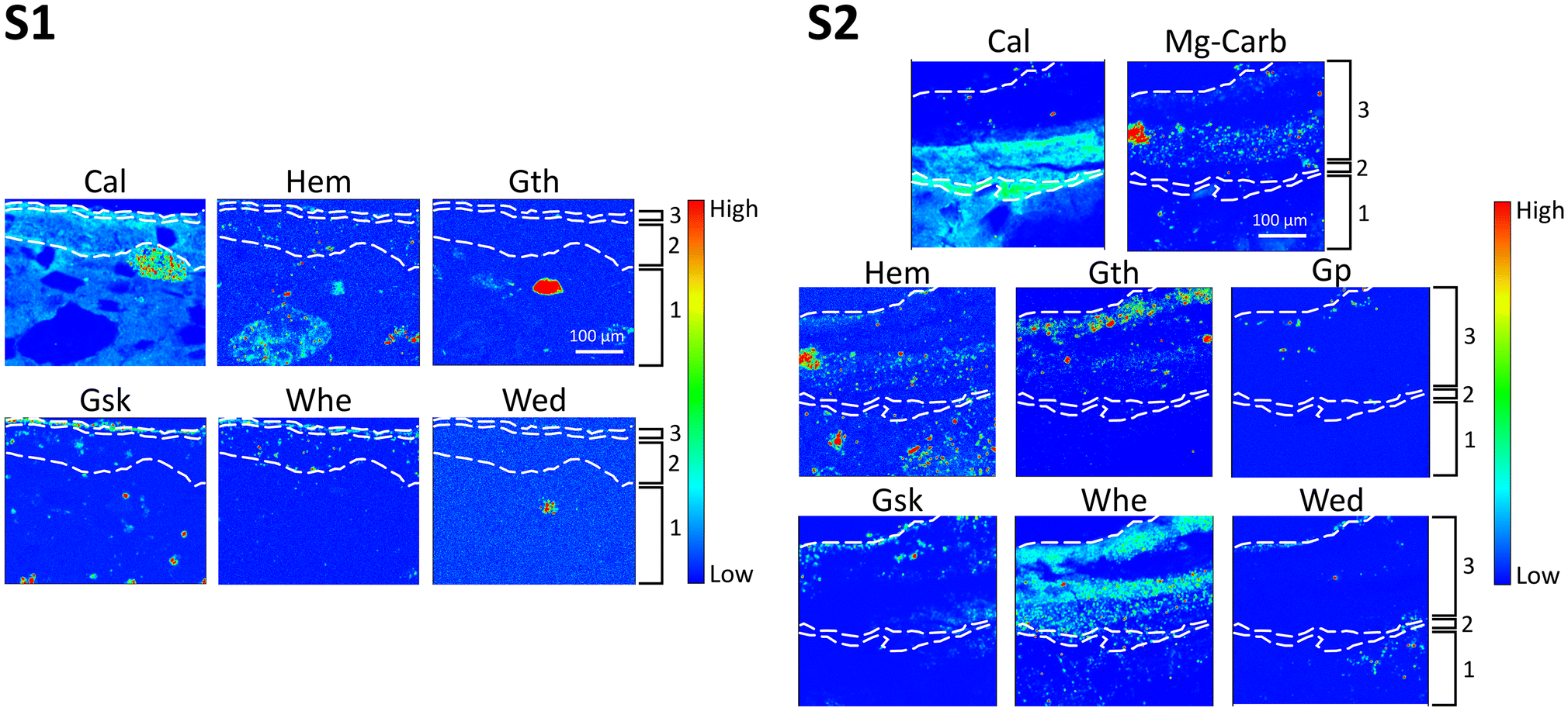 | ||
| Fig. 4 μXRD distribution maps collected at ID13 of samples S1 and S2, showing the spatial distribution of calcite (Cal), hematite (Hem), goethite (Gth), glushinskite (Gsk), whewellite (Whe), weddellite (Wed), Mg-containing carbonates (Mg-Carb), and gypsum (Gp) presented in a false colour thermal map spanning from low (blue) to high (red) values of relative intensity. The investigated ROI was of 496 × 410 μm2 horizontal × vertical (h × v) for sample S1 and of 400 × 415 μm2 (h × v) for sample S2. The dotted white lines highlight the layer sequence of the fresco in the two samples. | ||
| Crystalline phase | Label | Chemical formula | Integrated 2Theta range (°) | Peak position (°) | Interplanar distances (Å) and indexing of the selected Bragg peaks | PDF reference pattern |
|---|---|---|---|---|---|---|
| Calcite | Cal | CaCO3 | 17.90–18.23 | 18.09 | 3.03 (104) | 5–586 |
| Mg-calcite | Mg-Cal | Mg0.03Ca0.97CO3 | 17.90–18.23 | 18.20 | 3.02 (104) | 1–89–1304 |
| Glushinskite | Gsk | MgC2O4·2H2O | 11.04–11.32 | 11.18 | 4.89 (200) | 28–625 |
| Weddellite | Wed | CaC2O4·(2 + x)H2O | 8.81–9.05 | 8.91 | 8.73 (110) | 17–541 |
| Whewellite | Whe | CaC2O4·H2O | 9.04–9.40 | 9.26 | 5.93 (−101) | 20–231 |
| Gypsum | Gp | CaSO4·2H2O | 7.06–7.40 | 7.23 | 7.56 (020) | 6–46 |
| Hematite | Hem | Fe2O3 | 14.79–15.33 | 14.93 | 3.68 (012) | 33–664 |
| Goethite | Gth | FeO(OH) | 13.01–13.45 | 13.21 | 4.18 (110) | 29–713 |
| Quartz | Qtz | SiO2 | 12.66–13.00 | 12.85 | 4.25 (100) | 5–490 |
| Hydromagnesite | Mg-Carb | Mg5(CO3)4(OH)2·5H2O | 18.74–19.30 | 19.01 | 2.89 (310) | 25–513 |
| Lansfordite | MgCO3·5H2O | 18.74–19.30 | 19.01 | 2.89 (202) | 21–959 | |
| Dolomite | CaMg(CO3)2 | 18.74–19.30 | 19.01 | 2.89 (104) | 11–78 | |
| Fe-dolomite | Ca(Mg,Fe)(CO3)2 | 18.74–19.30 | 19.01 | 2.89 (104) | 34–517 |
Calcite (denoted as “Cal”), constituting the binder, is discernible in most of the fresco layers. The XRD peaks attributed to Cal appear at a slightly higher angular position compared to stoichiometric Cal, indicating a minor interplanar distance. This feature aligns with the peak position of magnesium-containing calcite (Mg-Cal), as indicated by the good match with PDF references and peak lists. The presence of Mg-Cal is also supported by the spatial distribution of Ca and Mg in the XRF datasets. Conversely, the presence of Mg in Mg-Cal should be minimal for phase stability and a potential coexistence of stoichiometric Cal with Mg-Cal can be hypothesized. Unfortunately, confirming this coexistence proved challenging, as the experimental setup prioritised spatial resolution over angular resolution, making it unfeasible to reliably 2D discern the distribution of these two phases. No MgO or Mg(OH) has been observed in those regions, in contrast to what has been observed in ref. 13.
Additional magnesium-containing carbonate phases (possibly dolomite, CaMg(CO3)2, iron-containing dolomite, Ca(Mg,Fe)(CO3)2, hydromagnesite, Mg5(CO3)4(OH)2·5H2O, and lansfordite, MgCO3·5H2O) were identified within the intonachino (both layer 2 and layer 3) portion of sample S2. The qualitative analysis of these different phases was very complex, even extracting point-specific diffraction patterns, as their XRD peaks displayed several overlapping areas, and they were mapped under the generic name Mg-carbonates in this study. These phases were observed in fine grained clusters, possibly forming agglomerates of the binder or very fine aggregates (Fig. 4).
The colour of the red painted layer is due to a complex mixture of hematite (“Hem”) and goethite (“Gth”), in mixture with other Ti- and Mn-containing minerals, typical of red earths (Fig. 2 and 4).
Focusing on the reaction products from the conservation treatment, the XRD patterns pinpoint that the AmOx treatment on the Mg-containing fresco painting results in the formation of two distinct categories of phases: magnesium oxalates (specifically glushinskite, MgC2O4·2H2O, denoted as “Gsk”) and calcium oxalates (specifically “Whe” and “Wed”). The XRD peaks of the newly formed oxalates were very pronounced in the case of S2. This observation suggests that in the more decayed sample (S2), the AmOx reaction and oxalate crystallisation were significantly more abundant than in the more compact and well-preserved S1 sample. Remarkably, no calcium oxalates (and other oxalates in general) were observed in the untreated micro samples used to characterize the mineralogical composition of the fresco before applying the AmOx conservation treatment (investigations performed by bulk powder XRD using a lab-scale diffractometer equipped with a conventional Cu source, see the section Materials and Fig. 1).
The crystallization of magnesium oxalates and calcium oxalates occurs in separate areas of both samples, with Gsk and Wed forming near the treated paint surface (<10–100 μm) and Whe being localized in the sub-surface section of the fresco painting in both samples. The spatial resolution of the SR μXRD–μXRF mapping and the high quality of the collected data allow to further distinguish the different spatial localisations of Gsk with respect to the Wed crystals. Indeed, the RGB correlation of their phase maps shows that the former were formed above the crystals of the latter (Fig. 5b), in correspondence to the Mg-enrichment of layer 3 (Fig. 5a). Remarkably, it is possible to distinguish the different spatial localisations, even of minor (or trace) phases and down to a 5–10 μm-thick region of the samples, such as in the detail of the three Ca and Mg oxalates in sample S1. In the more decayed and porous regions of the fresco of sample S2, the Wed–Gsk–Whe layer sequence was still visible, but a spotty crystallisation of Wed and Gsk was detected as well in more inner regions of the decayed paint layers (the inset of Fig. 5b). This is likely due to the decay of the matrix with the presence of diffusion paths, such as cracks or pores.
 | ||
| Fig. 5 (a) RGB correlations of the μXRF distribution maps of magnesium (Mg_K), iron (Fe_K) and calcium (Ca_K), showing Mg enrichment in the most external portion of the fresco. (b) RGB correlations of the μXRD distribution maps of calcite (Cal), weddellite (Wed), glushinskite (Gsk) and whewellite (Whe). The dotted white lines highlight the layer sequence of the fresco in the two samples. | ||
As shown in Fig. 5, the presence of calcium oxalate phases emerges both in the intonachino (layers 2 and 3) and in the arriccio (layer 1) substrates. By integrating different marker Bragg peaks of the newly formed oxalate phases, their spatial distribution in the μXRD maps remained consistent. This observation implies that the XRD patterns of the newly formed crystals closely resembles those of an ideal powder, characterised by patterns originating from thousands of fine-grained crystallites randomly distributed throughout the investigated volume or region, as much smaller than the beam size (∼2 μm). Consequently, this suggests that the newly formed crystals exhibit no preferential spatial orientation or specific direction of growth.
Gypsum (denoted as “Gp”), formed by the sulfation of the fresco's carbonatic matrix, could be detected in XRD 2D datasets (Fig. 3 and 4). It was in a very low amount in S1, so low that it was not possible to map it (but it can be seen in selected XRD diffraction patterns extracted from the datasets); however, it was slightly more abundant in sample S2 (see the XRD patterns in Fig. 3 and the Gp μXRD distribution map in Fig. 4). In agreement with the S distribution obtained in the ID21 μXRF maps (Fig. 2d), Gp was localised in all the layers of the fresco, with a higher content in layer 2 and in the inner part of layer 3. For both the samples, the most external part of layer 3 was almost without the presence of S or Gp, in the XRF and XRD maps, respectively.
Fig. 6 displays the RGB correlation of the μXRF distribution map of calcium with the μXRD maps of Cal and of Whe in both the samples. This figure, coupled with the spatial distribution of Gp in Fig. 4, sheds new light on the reactivity of the fresco substrate to the AmOx treatment and the phase transformations taking place during the AmOx reaction. Indeed, they reveal the following novel information: (i) in the top half of layer 3, all calcium ions were mainly attributed to calcium oxalate phases, with almost no presence of calcite and with no gypsum, and (ii) in the bottom half of layer 3, the calcium ions were attributed to the calcium oxalate phases, calcite of the matrix and gypsum.
 | ||
| Fig. 6 RGB correlation of the μXRD maps of calcite (Cal, red pixels) and of whewellite (Whe, blue pixels) together with the μXRF maps of calcium (Ca_K, green pixels) in samples S1 and S2. The dotted white lines highlight the layer sequence of the fresco in the two samples. | ||
These results disclose that a significant phase transformation occurs in the outer part of the intonachino (top half of layer 3), converting the majority of the original Cal (and likely of gypsum) into calcium oxalate phases. The calcite-to-whewellite conversion is particularly evident in the case of the decayed matrix of sample S2 (Fig. 6). In this instance, the phase transformation involves the entire thickness of 200 μm of the layer, with almost no detectable Cal remaining in that region.
In this light, the extensive oxalate crystallization can be attributed to the pronounced reactivity of AmOx with calcite of the fresco as well as to the decay of the fresco painting. As for the latter, the fresco exhibited instances of decohesion and sulfation. Firstly, decohesion contributed to: (i) an increase in the specific surface area of Cal grains within the binder, which becomes even more reactive toward AmOx and (ii) promotion of the AmOx diffusion in the inner portions of the fresco, leading to a widespread crystallisation in the subsurface regions. Secondly, the sulfation of Cal grains involves a partial phase transformation of Cal to Gp. This process, acting on the surface (and from the surface to the core) of Cal grains, increases the specific surface area of Cal grains which can be exposed to the AmOx treatment. Additionally, gypsum crystals are (i) soluble in water and (ii) reactive towards AmOx.35 Given that AmOx is typically administered in aqueous solutions, the presence of liquid water likely facilitated the availability of free calcium ions – originating from the dissolution of gypsum – for the crystallization of calcium oxalates. This process would further explain the extensive crystallisation of oxalates on top of the intonachino portion as well as the absence of gypsum in those same regions. Vice versa, the detection of few spotty gypsum crystals in the inner portion of the intonachino (bottom half of layer 3 and layer 2) suggests that these small regions did not react (or were less reactive) with the AmOx solution. This could be ascribed to the gypsum crystals localised in isolated pores or in poorly interconnected regions of the fresco pore network which were not reached by AmOx, or gypsum mobilised by water from the other regions of the fresco during post treatment rinsing and re-crystallised in those micro-areas after drying.
The μXRD results discussed until now showed the significant crystallisation of whewellite and pointed out that these new phases effectively reinstate the microstructural cohesion that was previously compromised during the past decay process. Remarkably, they also showed that the calcite-to-whewellite conversion is not confined to layer 3 but it persists with depth. These observations demonstrate the crucial role of the oxalate framework in reinstating the microstructural cohesion of the fresco across the layers.
However, although the XRD and XRF maps provide a lateral resolution at the microscale (beam footprint at ID13 approximately 2.5 × 2.5 μm2, step size of 1–2 μm), further analysis was required to investigate, at the micrometric and submicrometric levels, the morphology and spatial distribution of Ca- and Mg-containing newly formed phases: (i) surrounding the Fe-pigment grains, (ii) surrounding the Ca- and Mg- grains and (iii) at the fresco's surface, where glushinskite crystallization was identified. For this purpose, a set of SEM investigations was conducted on a very small area (approximately 10 × 15 μm2) within the outermost portion of the two samples, in correspondence to the Mg-rich and Fe-rich top areas. The results are shown in Fig. 7 and 8.
 | ||
| Fig. 7 Sample S2. Crystallization of new phases in correspondence to the Fe-based pigments and Ca- and Mg- agglomerates. (a) SEM BES images of layer 3; (b) detail of the SEM BES images at a higher magnification and the scheme (on the top right) showing the rounded morphology of the Fe-based particles of the pigment (in light grey) and the Ca-based newly formed network composed of micrometric and submicrometric middle grey crystallites having a plate-like or needle-like morphology; (c) detail of the SEM BES images at a higher magnification and the scheme (on the top right) of Ca- and Mg-containing grains surrounded by the newly-formed Ca-based shell; and (d) elemental distribution maps of calcium (Ca), magnesium (Mg) and silicon (Si). The dotted white lines mark the boundaries of the Ca and Mg grains and highlight the surrounding Ca-based shell. | ||
 | ||
| Fig. 8 Sample S2. (a) RGB correlation of the μXRD maps of glushinskite (Gsk, red pixels) and of whewellite (Whe, green pixels) together with the μXRF maps of iron (Fe_K, blue pixels). (b) On the left, the SEM BES image at a high magnification of the most external region of layer 3. The yellow line shows the direction used for the linear EDS measurements performed to map the amount and distribution of Mg–K, Si–K, Ca–K and Fe–K (plot on the right). (c) The SEM BES image at a high magnification of the most external region of layer 3 and elemental distribution maps of Ca–K, Mg–K, Fe–K, Si–K and S–K. (d) Scheme not in scale of the stratigraphy of crystalline phases (weddellite – Wed; glushinskite – Gsk, whewellite – Whe and calcite – Cal) and marker elements (silicon – Si and iron – Fe) obtained by the synergy of SR μXRF–μXRD datasets and SEM–EDS investigations. | ||
Starting from point (i), a crystal network of micrometric and submicrometric middle grey crystallites having a plate-like or needle-like morphology was observed and are shown in the SEM images of Fig. 7a – in that areas were identified by μXRD maps as containing oxalates. These crystallites form a ∼1–5 μm-thick shell that surrounds the pigment grains (Fig. 7a and b), which are clearly recognisable by the typical rounded sub-micrometric morphology and light grey hue of heavy elements (Fig. 7a and b, in the scheme of Fig. 7b, and in the ∼5 μm-thick layer above the paint layer of Fig. 8). The formation of new crystallites around the pigment grains is crucial for several reasons: firstly, it reconnects the pigment grains that, due to decay, were no longer firmly integrated within the matrix; secondly, calcium oxalates are generated from the calcium present in calcite and gypsum, hence there is a desulfation action of the substrate; and thirdly, the oxalates establish a new, highly interconnected crystal framework, within which the pigment particles remain ensconced. Consequently, the newly formed shell replace/restore the cohesive action at the submicrometric scale that was once carried out by the lime binder. Above all, this underscores the real effectiveness of the oxalate treatment in enhancing microstructural cohesion within the decayed matrix of the fresco.
As for point (ii), i.e. compounds surrounding the Ca and Mg crystals, the scheme of Fig. 7c and the SEM elemental maps of Fig. 7d illustrate that the newly formed phases form a shell also on the surface of the Ca- and Mg-containing grains found in the intonachino. These grains, which correspond to the Ca and Mg carbonate agglomerates identified in the XRD patterns and shown in the μXRD maps, were linked to each other by this shell. Remarkably, the shell formed around these Ca and Mg agglomerates was composed solely of Ca (Fig. 7c and d). This suggests that the surface of the Ca and Mg agglomerates did not react with AmOx, or that, at least, Mg ions released from the Ca and Mg agglomerates were less reactive to AmOx than those from the Ca ones. Further studies are planned to investigate whether during the AmOx reaction: (a) Ca and Mg agglomerates retain Mg without releasing it, or (b) they release Mg, which then migrates to the fresco surface, leading to the formation of Gsk. These novel findings obtained, thanks to the higher magnification provided by SEM, complement the new knowledge extracted from the μXRF–μXRD maps, demonstrating here, for the first time, (i) the clear bridge action of the new Ca-based phases among the Ca and Mg carbonate aggregates, and therefore the (ii) capability of AmOx to re-connect even non-reactive (or less-reactive) Mg-carbonate agglomerates.
Moving to point (iii), i.e. the fresco surface, the synergy of SEM–EDS investigations and the μXRD–μXRF map was used to study the morphology and spatial arrangement of Ca-containing and Mg-containing phases in correspondence to the surface of the fresco, where the crystallization of Gsk was revealed.
The RGB correlation of the μXRD–μXRF maps of Fig. 8a reveals that in the top half region of the Fe-based layer, the newly formed oxalate shell was mainly composed of Gsk (red area in Fig. 8a). Conversely, Whe was mainly formed from the middle to the inner part of layer 3 (green areas in Fig. 8a). In addition, there was a very thin layer and/or spotty regions where Gsk and Whe coexisted (yellow areas of Fig. 8a).
These μXRD–μXRF findings, collected on both samples, suggest a very thin phase stratigraphy (<10 μm) that transitions from a layer containing only Gsk at the outer part of layer 3, to a mixture of Gsk + Fe + Whe in the middle, and finally to Whe in the innermost part. The actual presence of this stratigraphy was finally observed through the SEM–EDS analysis. Here, the high magnification of SEM and linear EDS analyses, spanning from the surface through layer 3 (Fig. 8b), distinctly revealed a defined Mg-rich layer overlying a Ca-rich matrix. Additionally, the elemental maps in Fig. 8c underscored the Ca presence on top of the Mg-rich layer, likely ascribed to the crystallisation of Wed, as shown by the μXRD maps.
Interestingly, an enrichment of Si was observed between the Mg and the inner Ca layers. This Si presence was attributed to clay minerals (from the kaolinite group) contained in the earth pigments as accessory minerals.46 However, isolating their XRD signals was not feasible as they were trace phases in a layer approximately 5 μm thick. Remarkably, Si was not localised in the same region as Fe but instead appeared in a higher layer, just below the Mg enrichment. These SEM–EDS findings suggest a migration of clay minerals toward the interface between the fresco and the AmOx poultice during the AmOx reaction and subsequent drying of the solution.
Notably, no iron-oxalates have been detected, indicating no reaction occurred with the pigments – a significant result that underscores the high compatibility of AmOx treatments for the conservation of iron-containing wall paintings and frescoes.
Overall discussion
So far, the high quality datasets of SR of μXRF–μXRD and SEM–EDS demonstrate that the AmOx reaction with the decayed Mg-lime of historical frescos promotes the formation of new oxalates above, within and below the intonachino paint layer. These oxalates are organized into distinctive phase stratigraphies, including (i) stratigraphy between oxalates themselves, (ii) oxalates vs. iron and (iii) oxalates vs. minerals of the matrix, whose phase sequence is illustrated in the scheme of Fig. 8d.The weddellite–glushinskite–whewellite phase stratigraphy was observed starting from the surface of the fresco. This happens regardless of the state of conservation of the fresco matrix (decohesion degree; amount of gypsum in the matrix) or the thickness of the layers (spanning from a few micrometers to a hundred of micrometers).
Despite magnesium being widely present in the whole stratigraphy, both in the magnesium lime and magnesium carbonate aggregates, magnesium oxalates (glushinskite) are detected only close to the treated surface of the fresco, arranged in a thin layer.
Our findings suggest that the reaction of AmOx takes place mainly (or only) with the Mg fraction of the lime binder and not (or less) with the Mg-containing aggregates. Moreover, Mg migration vs. the surface is highly likely, where Mg2+ ions find reaction conditions favourable to promote the crystallisation of glushinskite. Further studies are planned to better explore the distribution of Ca and Mg during the AmOx reaction and therefore understand possible migrations in the selected regions of the fresco.
A similar location of crystallization is observed for weddellite crystallites, which nucleate only on the surface of the fresco although Ca2+ cations are widely present in the lime all through the fresco stratigraphy. These results imply that there are distinct reaction and crystallization conditions at the interface between the fresco surface and the AmOx poultice, differing in pH and ionic strengths from those existing within the inner portions.15,20,25,47,48
The formation of calcium oxalates is more abundant in the most decayed regions of the fresco. This pronounced crystallisation is attributed to higher Ca2+ cation availability, which resulted from several factors such as: (i) the microstructural decohesion of Cal crystals in the lime binder exposed a high specific surface area to the AmOx solution, thereby enhancing the reactivity of the carbonatic substrate to the reagent, (ii) Cal grains underwent chemical deterioration as well, notably sulfation, which led to the dissolution of their external surfaces, and consequently, this exposure resulted in a higher specific surface area of Cal grains available for reaction with the AmOx, and (iii) gypsum crystals formed through the sulfation of lime during the decay were within the fresco matrix and they easily dissolved in the AmOx solution to release Ca2+ ions.
The oxalates formed on the surface of the paint layer protect the subsurface materials from the outside. By crystallising on the external decayed profile of the fresco, these oxalate phases restore the roughness of the decayed external fresco profile. In turn, this external crystallisation changed the scattering of the light, providing a positive optical effect on colour saturation, demonstrated by the colour measurements carried out on the fresco and discussed by Realini et al. in ref. 37.
The crystallisation of whewellite within the intonachino paint layer replaces the carbonatic binder and generates a novel crystal network embedding the pigments and bridging the Ca and Mg carbonate grains. By doing that, the oxalate crystal network demonstrates a clear microstructural cohesion action within the paint layer of the fresco. Moreover, by being surrounded by the oxalate shell, the pigment grains and the carbonate aggregates were less reachable from the environmental agents. In addition, the low solubility of the reaction products even to acid environments19 is expected to provide beneficial acid resistance for painted carbonate substrates exposed to polluted urban regions. Lastly, the detection of oxalates in the intonachino portion and in the arriccio portion demonstrates the action of re-connection performed by the AmOx treatment between the layers of the fresco. Moreover, the gradient of the crystallisation which gradually decreases with depth (no abrupt interruption) is expected to supply a decrease in the cohesion effect.
Therefore, we can now assert the protective, passivating and consolidating 2D action of AmOx for Cal grains, pigments and aggregates within a decayed Mg-containing layered matrix of a fresco. This statement represents a significant milestone in conservation science as it broadens our understanding of the AmOx reaction with Mg-containing carbonatic matrixes and integrates previous literature findings on the reactivity of artificial layered decayed stone materials to inorganic mineral treatments.
Consequently, the primary contribution of this study extends beyond the investigation of the AmOx treatment on a specific fresco and its variations, as it highlights the substantial potential of SR μXRF–μXRD mapping to extrapolate specific crystallisation trends in complex polycrystalline layered systems.
Conclusions
This paper shows the novel application and high analytical potential of SR 2D μXRF–μXRD mapping to non-destructively explore the effects induced by the AmOx inorganic mineral conservation treatment on the decayed, layered, Mg-containing stone matrixes of frescoes from cultural heritage exposed to outdoor conditions.The synergy of a micro-resolved spatial resolution, elemental/structural analysis, morphological observations, and mapping capabilities allowed performing qualitative characterization and 2D localization of newly-formed oxalates formed in a complex mixture, as well as characterizing and spatially localizing minor phases displaying a very similar chemical composition, and formed in the micrometric regions of the treated substrate.
The possibility of mapping the chromophore element of the paint stratigraphy with respect to the newly-formed phases was crucial for studying the reaction of the treatment at the interface with the pigments at a very pixel size resolution as well as for defining the diffusion of the reaction products within these complex multiphase and layered systems.
One of the major achievements of this study is the demonstration of the multimodal action of the AmOx treatment applied to fresco mural paintings, which includes the capability of AmOx to (i) consolidate the microstructure of decayed matrixes, (ii) isolate the pigment grains as well as the paint layers from the environmental agent, (iii) passivate the paint surface vs. acid dissolution, and (iv) restore the microstructural cohesion of the fresco stratigraphy across the layers.
Looking at the broader picture, the strength of this study lies in its capability to provide novel analytical perspectives, including the need to broaden our knowledge on inorganic treatments, including dynamic studies on the reactivity and ion mobility of Mg during inorganic treatments with studies of mock-ups.
Moreover, by showcasing the potential of SR 2D μXRF–μXRD mapping to investigate the effects induced by inorganic conservation products in CH layered stone materials, our study (i) provides new analytical tools to understand the conservation processes and reactions, and therefore to define novel conservation strategies for decayed Mg-containing artefacts of CH, (ii) unveils new analytical possibilities for μXRF–μXRD mapping in conservation science, and (iii) opens new horizons in analytical chemistry and materials characterisation, including the possibility of performing a qualitative and quantitative phase characterisation, non-destructive analysis of heterogeneous polycrystalline systems.
Author contributions
Conceptualization, E.P. and C.C.; methodology, E.P.; investigation, formal analysis and data curation, E.P. and M.C.; writing – original draft, E.P.; writing – review & editing, E.P., C.M., M.C., M.R. and C.C; supervision, E.P. and C.C.Data availability
The raw SR datasets are available on the ESRF data portal at https://doi.esrf.fr/10.15151/ESRF-DC-2007330111 for the μXRF–μXRD 2D maps collected at ID13 and at https://doi.esrf.fr/10.15151/ESRF-DC-2087451479 for the μXRF 2D maps collected at ID21. Other data are available upon request to the authors.Conflicts of interest
There are no conflicts to declare.Acknowledgements
The ESRF-EBS beamtime was granted through the peer-review Historical Materials Block Allocation Group (BAG) proposal HG-172 at ID13 and the in-house IH-HG-17 beamtime at ID21. The Historical Materials BAG project HG-172 is supported by the European Union's Horizon 2020 Research and Innovation Programme under grant agreement no. 870313, Streamline. We thank Dr Loïc Huder for data analysis tools (Jupyter notebooks) and Dr Manfred Burghammer for assistance in using beamline ID13. The authors sincerely acknowledge the TS Lab & Geoservices s.n.c (Cascina, Pisa, Italy) for developing a new effective protocol to prepare ad hoc polished thin sections on polycarbonate films suitable for μXRD–μXRF investigations at ID13 and ID21, Alessandro Suranna for performing the SEM–EDS investigations, and JEOL Italia S.p.a. for providing access to the JSM-IT200LA scanning electron microscope, and Dr Roberta Possenti for her support in the image graphic design.References
- M. Cotte, V. Gonzalez, F. Vanmeert, L. Monico, C. Dejoie, M. Burghammer, L. Huder, W. de Nolf, S. Fisher, I. Fazlic, C. Chauffeton, G. Wallez, N. Jiménez, F. Albert-Tortosa, N. Salvadó, E. Possenti, C. Colombo, M. Ghirardello, D. Comelli, E. Avranovich Clerici, R. Vivani, A. Romani, C. Costantino, K. Janssens, Y. Taniguchi, J. McCarthy, H. Reichert and J. Susini, Molecules, 2022, 27, 1997 CAS.
- M. Cotte, J. Susini, V. A. Solé, Y. Taniguchi, J. Chillida, E. Checroun and P. Walter, J. Anal. At. Spectrom., 2008, 23, 820–828 RSC.
- K. Janssens, M. Alfeld, G. Van der Snickt, W. De Nolf, F. Vanmeert, M. Radepont, L. Monico, J. Dik, M. Cotte, G. Falkenberg, C. Miliani and B. G. Brunetti, Annu. Rev. Anal. Chem., 2013, 6, 399–425 CrossRef CAS PubMed.
- M. Cotte, K. Dollman, V. Fernandez, V. Gonzalez, F. Vanmeert, L. Monico, C. Dejoie, M. Burghammer, L. Huder, S. Fisher, W. de Nolf, I. Fazlic, H. Castillo-Michel, M. Salomé, M. Ghirardello, D. Comelli, O. Mathon and P. Tafforeau, Synchrotron Radiat. News, 2022, 35, 3–9 CrossRef.
- D. Mudronja, F. Vanmeert, S. Fazinic, K. Janssens, D. Tibljas and V. Desnica, Coatings, 2021, 11, 379 CrossRef CAS.
- V. Gonzalez, M. Cotte, G. Wallez, A. van Loon, W. de Nolf, M. Eveno, K. Keune, P. Noble and J. Dik, Angew. Chem., Int. Ed., 2019, 58, 5619–5622 CrossRef CAS PubMed.
- M. Ghirardello, V. Gonzalez, L. Monico, A. Nevin, D. MacLennan, C. S. Patterson, M. Burghammer, M. Réfrégiers, D. Comelli and M. Cotte, Microsc. Microanal., 2022, 28, 1–10 CrossRef PubMed.
- V. Gonzalez, G. Wallez, T. Calligaro, M. Cotte, W. De Nolf, M. Eveno, E. Ravaud and M. Menu, Anal. Chem., 2017, 89, 13203–13211 CrossRef CAS PubMed.
- V. Gonzalez, I. Fazlic, M. Cotte, F. Vanmeert, A. Gestels, S. De Meyer, F. Broers, J. Hermans, A. van Loon, K. Janssens, P. Noble and K. Keune, Angew. Chem., Int. Ed., 2023, 62, e202216478 CrossRef CAS PubMed.
- M. Gomez Lobon, M. Ghirardello, E. Juncosa Darder, C. Palomino Cabello, M. Bauza, M. Cotte, A. Burnstock, A. Nevin, S. R. Amato, F. C. Izzo and D. Comelli, Heritage Sci., 2023, 11, 145 CrossRef CAS.
- V. Gonzalez, G. Wallez, E. Ravaud, M. Eveno, I. Fazlic, T. Fabris, A. Nevin, T. Calligaro, M. Menu, V. Delieuvin and M. Cotte, J. Am. Chem. Soc., 2023, 145, 23205–23213 CrossRef CAS PubMed.
- A. Suzuki, C. S. Cheung, Y. Li, A. Hogg, P. S. Atkinson, C. Riminesi, C. Miliani and H. Liang, Analyst, 2024, 149, 2338–2350 RSC.
- N. Oriols, N. Salvadó, T. Pradell, N. Jiménez, M. Cotte, V. Gonzalez and S. Butí, Cem. Concr. Res., 2022, 157, 106828 CrossRef CAS.
- V. Gonzalez, M. Cotte, F. Vanmeert, W. de Nolf and K. Janssens, Chem. – Eur. J., 2020, 26, 1703–1719 CrossRef CAS PubMed.
- G. Massinelli, N. Marinoni, C. Colombo, G. D. Gatta, M. Realini, M. Burghammer and E. Possenti, Sci. Rep., 2024, 14, 9108 CrossRef CAS PubMed.
- E. Villani, A. Suzuki, M. Ricci, B. Salvadori, S. Vettori and E. Cantisani, Analyst, 2024, 149, 4872–4880 RSC.
- E. Beauvoit, A. Bouquillon, O. Majérus, D. Caurant, J. Cuny and A. Thomas, Heritage, 2023, 6, 6291–6310 CrossRef.
- E. Hansen, E. Doehne, J. Fidler, J. Larson, B. Martin, M. Matteini, C. Rodriguez-Navarro, E. S. Pardo, C. Price, A. de Tagle, J. M. Teutonico and N. Weiss, Stud. Conserv., 2003, 48, 13–25 CrossRef.
- M. Matteini, Conserv. Sci. Cult. Heritage, 2008, 8, 13–27 Search PubMed.
- E. Possenti, N. Marinoni, C. Conti, M. Realini, G. B. M. Vaughan and C. Colombo, Analyst, 2024, 149, 2059–2072 RSC.
- F. Vanmeert, D. Mudronja, S. Fazinic, K. Janssens and D. Tibljas, X-Ray Spectrom., 2013, 42, 256–261 CrossRef CAS.
- T. Dreyfuss, J. Cult. Heritage, 2020, 42, 56–63 Search PubMed.
- I. Osticioli, G. Botticelli, P. Matteini, S. Siano, R. Pini and M. Matteini, J. Raman Spectrosc., 2017, 48, 966–971 CrossRef CAS.
- C. Conti, C. Colombo, D. Dellasega, M. Matteini, M. Realini and G. Zerbi, J. Cult. Heritage, 2011, 12, 372–379 Search PubMed.
- E. Possenti, C. Colombo, M. Realini, C. L. Song and S. G. Kazarian, Anal. Chem., 2021, 93, 14635–14642 Search PubMed.
- C. Conti, M. Casati, C. Colombo, M. Realini, L. Brambilla and G. Zerbi, Spectrochim. Acta, Part A, 2014, 128, 413–419 Search PubMed.
- M. Realini, C. Colombo, C. Conti, F. Grazzi, E. Perelli Cippo and J. Hovind, Anal. Bioanal. Chem., 2017, 409, 6133–6139 Search PubMed.
- C. Conti, C. Colombo, G. Festa, J. Hovind, E. P. Cippo, E. Possenti and M. Realini, J. Cult. Heritage, 2016, 19, 463–466 CrossRef.
- N. Calore, A. Botteon, C. Colombo, A. Comunian, E. Possenti, M. Realini, D. Sali and C. Conti, Vib. Spectrosc., 2018, 98, 105–110 CrossRef CAS.
- L. Rampazzi, J. Cult. Heritage, 2019, 40, 195–214 CrossRef.
- E. Sassoni, E. D'Amen, N. Roveri, G. W. Scherer and E. Franzoni, Materials, 2018, 11, 1–16 Search PubMed.
- C. Conti, L. Cutard, A. Botteon, L. Brambilla, N. Marinoni, M. Realini, M. Catrambone, E. Possenti and C. Colombo, Crystals, 2023, 13, 1212 CrossRef CAS.
- E. Possenti, C. Conti, G. D. Gatta, M. Realini and C. Colombo, Coatings, 2019, 9, 169 CrossRef.
- E. Possenti, C. Colombo, C. Conti, L. Gigli, M. Merlini, J. R. Plaisier, M. Realini, D. Sali and G. D. Gatta, Constr. Build. Mater., 2019, 195, 557–563 CrossRef CAS.
- T. Dreyfuss, Heritage Sci., 2019, 7, 5 CrossRef.
- A. Botteon, C. Castiglioni, P. Matousek, M. Realini, C. Colombo and C. Conti, J. Cult. Heritage, 2022, 57, 26–33 Search PubMed.
- M. Realini, C. Colombo and C. Conti, Comportamento del trattamento ad ossalato di ammonio su superfici dipinte esterne, 2015 Search PubMed.
- ICOMOS-ISCS, Illustrated glossary on stone deterioration patterns Glossaire illustré sur les formes d'altération de la pierre, 2008, pp. 1–78 Search PubMed.
- M. Cotte, E. Pouyet, M. Salomé, C. Rivard, W. De Nolf, H. Castillo-Michel, T. Fabris, L. Monico, K. Janssens, T. Wang, P. Sciau, L. Verger, L. Cormier, O. Dargaud, E. Brun, D. Bugnazet, B. Fayard, B. Hesse, A. E. Pradas del Real, G. Veronesi, J. Langlois, N. Balcar, Y. Vandenberghe, V. A. Solé, J. Kieffer, R. Barrett, C. Cohen, C. Cornu, R. Baker, E. Gagliardini, E. Papillon and J. Susini, J. Anal. At. Spectrom., 2017, 32, 477–493 RSC.
- S. Fisher, M. Oscarsson, W. De Nolf, M. Cotte and J. Meyer, J. Synchrotron Radiat., 2021, 28, 1996–2002 Search PubMed.
- C. Riekel, M. Burghammer and R. Davies, IOP Conf. Ser.: Mater. Sci. Eng., 2010, 14, 12013 Search PubMed.
- J. Kieffer, V. Valls, N. Blanc and C. Hennig, J. Synchrotron Radiat., 2020, 27, 558–566 CrossRef CAS PubMed.
- V. A. Solé, E. Papillon, M. Cotte, P. Walter and J. Susini, Spectrochim. Acta, Part B, 2007, 62, 63–68 Search PubMed.
- M. Cotte, T. Fabris, G. Agostini, D. Motta Meira, L. De Viguerie and V. A. Solé, Anal. Chem., 2016, 88, 6154–6160 CrossRef CAS PubMed.
- L. N. Warr, Mineral. Mag., 2021, 85, 291–320 CrossRef CAS.
- Artist's Pigments: A Handbook of their History and Characterization, ed. B. H. Berrie, Oxford University Press, 2007, vol. 4 Search PubMed.
- D. Y. Vlasov, M. S. Zelenskaya, A. R. Izatulina, S. Y. Janson and O. V. Frank-Kamenetskaya, Crystals, 2023, 13, 432 CAS.
- E. Possenti, C. Conti, G. D. Gatta, N. Marinoni, M. Merlini, M. Realini, G. B. M. Vaughan and C. Colombo, iScience, 2022, 25, 105112 CrossRef CAS PubMed.
| This journal is © The Royal Society of Chemistry 2025 |