DOI:
10.1039/D3YA00509G
(Paper)
Energy Adv., 2024,
3, 203-214
An aqueous polysulfide redox flow battery with a semi-fluorinated cation exchange membrane†
Received
14th October 2023
, Accepted 24th November 2023
First published on 25th November 2023
Abstract
The vast availability and environmental benignity of polysulfide–ferricyanide redox flow batteries (PSFRFBs) have attracted much deserving attention. However, the commercial scalability of polysulfide-based batteries is hindered by the expensive commercial ion exchange membrane and also the sluggish kinetics of polysulfide. Herein, we report an economically viable, thermally annealed PVDF-co-HFP-based cation exchange membrane (T-CEM). Thermal densification of the membrane mitigated the cross-contamination of polysulfide and ferro/ferri species across the membrane, whereas controlled sulfonation allowed smooth conduction of charge carriers. The diffusion coefficient values were 4.57 × 10⁻¹¹ and 3.05 × 10⁻¹² dm2 s−1 for polysulfide and ferricyanide, respectively, better than those of commercial separators. The polarization curve experiment depicted a power density of 220 mW cm−2 at 400 mA cm−2 current density. The flow battery exhibited capacity retention of 88% with average capacity decay of 0.12% per cycle, 99.4% coulombic efficiency and 63.0% energy efficiency over 250 uninterrupted charge/discharge cycles at 40 mA cm−2 current density, and the long durability characteristic revealed high efficacy and the best usability in PSFRFBs. Furthermore, the facile densification strategy demonstrated in this work can be employed to fabricate better ion exchange membranes for energy device applications and separation/purification.
1. Introduction
Synchronized research and development of energy storage technologies and renewable energy generation sources will enable the design of a simple yet effective integrated grid energy storage system to fulfil the global need for clean and sustainable energy.1 Relatively cost effective, safe, and independent power and energy scale-up features of redox flow batteries (RFBs) have attracted deserving attention.2–5 In RFBs, the chemical energy in the form of dissolved redox molecules is stored in scalable external reservoirs, which can be converted into electrical energy by pumping the electrolyte solution through a cell made of electrodes and a semi permeable separator.6 Amongst the existing RFBs, the vanadium redox flow battery (VRFB) is the most extensively studied and commercialized system.7 However, VRFBs are endowed with several demerits that limit their global widespread market penetration. One example is the sky-rocketing price of vanadium, as a study based on simulations confirmed an increase in the vanadium price after 2030 owing to its scarcity;8 in addition, a recent comprehensive study on the economics of flow batteries revealed USD$ 24 kg−1 as the cost of the vanadium chemical in bulk quantity, which is at least ten times higher than that of the principal chemicals preferred in other emerging redox flow batteries such as zinc-based flow battery, iron based flow battery, etc.9 Other issues include the acidic and oxidative battery environment due to the high molar concentration of sulfuric acid as a supporting electrolyte and the high-valent vanadium species,10 and low energy density (20–33 W h L−1)11 compared to some other flow batteries like zinc-iodide (energy density: 125 W h L−1), and polysulfide-based flow batteries (energy density: 43 W h L−1).12,13 Other redox flow batteries are zinc-based flow batteries, iron-based flow batteries, organic flow batteries etc. Grave challenges of zinc-based flow batteries are severe dendrite formation at higher operating current densities. Challenges associated with iron-based systems include the sluggish kinetics of the electrode. Organic redox flow batteries suffer from oxidative stability of the redox active species, and tedious and high-cost synthetic route.14–17
Polysulfide-based RFBs are eligible candidates for energy storage due to their high solubility, and the vast availability of redox active materials ensures their low cost;18–21 for instance, Li et al. demonstrated a remarkably lower material cost per kilowatt hour of ∼$85 kW h−1 for a polysulfide-based flow battery compared to ∼$150 kW h−1 for a vanadium redox flow battery.18 Unlike VRFBs, polysulfide-based flow batteries are operatable in neutral supporting electrolytes, which enables safe-handling of the system, low-maintenance and environment friendly nature. In addition, low solubility of vanadium salts in acidic electrolyte restricts the energy density of the system, while as mentioned earlier, high solubility of polysulfide provides a clear-cut advantage to polysulfide-based systems over VRFBs. However, their commercialization is prohibited by sluggish reaction kinetics and severe cross-pollution of redox active species leading to faster self-discharge of the system.22 Use of an electrocatalyst is an efficient strategy to alleviate electron transfer during electrochemical reactions of polysulfides.23 Like any other RFB system, Nafion is the most preferred separator for polysulfide-based RFBs.24–26 It is worth mentioning that Nafion membranes were initially used as a separator membrane in the chloro-alkali industry, but its striking proton conductivity and robust mechanical and chemical stabilities led to quick adaption in proton exchange membrane fuel cells (PEMFCs) and RFBs.27–29 However, its poor selectivity due to well-structured hydrophilic ion cluster channels (∼4 nm in diameter)30 in the hydrated form results in migration of polysulfide redox active species across the membrane causing severe cross-contamination and hence associated irreversible side reactions, which eventually drags down the efficiencies and capacity retention of the battery.31 Li et al. tried to address this issue by creating a polyvinylidene fluoride bound carbon layer on the Nafion membrane.32 This approach was successful to create a barrier for polysulfide and polyiodide and mitigate water transport resulting in a low-capacity decay battery, but the use of pristine Nafion membrane remains a concern due to poor ion selectivity, which affects the overall efficacy of the flow battery performance and its high cost remains an obstacle in the development of redox flow batteries for large scale grid storage.33 A similar approach was used in lithium polysulfide RFB in which a porous carbon nanotube and boron nitride layer was used to block the cross-over of polysulfide and reduction of membrane–electrode interfacial resistance.34
Semi-fluorinated ion-exchange membranes (IEMs) are sought as an alternative for the perfluorinated IEMs.35 It is reported that polymers with 60–70% fluorine content can provide good chemical stability in an acidic oxidative environment.36 The bond energy for C–F is 485 kJ mol−1, quite a bit higher than the bond energy for C–H.37 Also, the van der Waals force of attraction between fluorine and hydrogen atoms enables high thermal and mechanical stability.38 Semi-fluorinated IEMs from polyvinylidene fluoride (PVDF), poly(vinylidene fluoride-co-hexafluoropropylene), poly(vinylidene fluoride-co-tetrafluoroethylene), poly(vinylidene fluoride-co-chlorotrifluoroethylene), poly(vinylidene fluoride)-graft-poly(styrene sulfonic acid) and poly(vinylidene fluoride–trifluoroethylene) are deployed in various membrane influential applications based on separation/purification and energy.39
Various membrane fabrication techniques such as solvent evaporation, phase inversion, electrospinning, layer-by-layer, and interfacial polymerization are used for developing high performance IEMs,40 and melt or blow film extrusion has also been attempted to create dense IEMs.41 Mokrini and co-workers studied a series of composite proton exchange membranes synthesized by blending extrusion grade Nafion and inorganic nanoparticles using the melt-extrusion technique.42 The Paul group successfully prepared a single layer sulfonated polysulfone desalination membrane by using melt extrusion.43 Mbarek et al. demonstrated improvement in the electrochemical and physicochemical properties for the extruded perfluorinated commercial membranes.44 Our group has reported interpolymer ion exchange membranes by blow film extrusion using polystyrene-co-divinyl benzene/poly(methyl styrene)-co-divinyl benzene in a polyethylene matrix.41
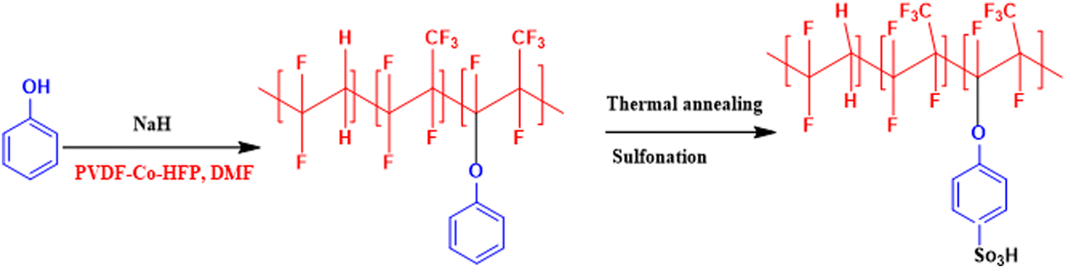
In an attempt to develop a semi-fluorinated backbone-based dense membrane for polysulfide RFB, we report a poly(vinylidene fluoride-co-hexafluoropropylene) (PVDF-co-HFP)-based cation exchange membrane (CEM). The polymer material for the membrane was prepared by attachment of phenol on the PVDF-co-HFP backbone in the presence of a strong base. The thermal annealing of the membrane before sulfonation ensured concealing of micro voids to create an obstruction for polysulphide and ferro/ferri redox active species cross-over across the membrane, while controlled sulfonation paved easier conduction of charge balancing counter-ions.
2. Experimental section
2.1 Materials
Poly(vinylidene fluoride-co-hexafluoropropylene) (PVDF-co-HFP) pellets (average molecular weight (Mw) ∼ 400![[thin space (1/6-em)]](https://www.rsc.org/images/entities/char_2009.gif) 000, number average molecular weight (Mn) ∼ 130000) were procured from Otto chemicals, India. Phenol from Finar, India. Sodium hydride (NaH) (57–63% oil dispersion) from GLR Innovations, India. N,N-Dimethylacetamide (DMAc), chlorosulfonic acid and potassium ferricyanide (K3Fe(CN)6) from Qualigens, India. Potassium chloride (KCl) from Research-lab Fine Chem Industries, India. Potassium polysulfide and sodium chloride (NaCl) from Thermo Scientific.
000, number average molecular weight (Mn) ∼ 130000) were procured from Otto chemicals, India. Phenol from Finar, India. Sodium hydride (NaH) (57–63% oil dispersion) from GLR Innovations, India. N,N-Dimethylacetamide (DMAc), chlorosulfonic acid and potassium ferricyanide (K3Fe(CN)6) from Qualigens, India. Potassium chloride (KCl) from Research-lab Fine Chem Industries, India. Potassium polysulfide and sodium chloride (NaCl) from Thermo Scientific.
2.2 Preparation of PVDF-co-HFP based CEM
In a 100 mL round bottom flask, phenol (5 g, 51 mmol) was dissolved in 25 mL DMAc to obtain a clear and homogeneous solution. To this, sodium hydride (NaH) was slowly added under cold and inert conditions. The reaction mixture was stirred for 2 h to ensure the complete residing of hydrogen gas bubbles formed during the spontaneous reaction between phenol and NaH. PVDF-co-HFP (5 g) dissolved in 25 mL DMAc was then added to the phenol–NaH mixture with continuous stirring. The stirring was continued for 24 h, and precipitated in 1 M HCl. The precipitate was collected by filtration, washed with a copious amount of water, and dried under vacuum. A 10% solution of obtained polymer in DMAc was then poured into a glass plate and dried underneath a casting chamber equipped with an infra-red (IR) lamp. After complete evaporation of the solvent, the membrane was thermally annealed in a muffle furnace at 175 °C with a heating rate of 5 °C min−1 for 1 h followed by sulfonation in 75% chlorosulfonic acid at 60 °C for 30 h. The obtained membrane was designated as T-CEM.
2.3 Membrane characterization
The attachment of phenol onto the PVDF-co-HFP backbone was confirmed with 1H-NMR spectra obtained on a Bruker DMX-300 NMR instrument at 500 MHz in DMSO-d6 solvent. A Fourier-transform infrared (ATR-FTIR) spectrophotometer with attenuated total reflectance (Agilent Technologies, Cary 600 series) was used to interpret the functional groups present in the membrane. The effect of thermal treatment on the morphology and surface of the membrane was visualized with a JSM-7100F (made in Japan) field emission scanning electron microscope. A Zwick Roell BT-FR 2.5TH 40 Universal Testing Machine (UTM) was used to analyse the mechanical strength of the membranes. The glass transition temperature (Tg) and melting temperature (Tm) of the membrane were obtained from a NETZSCH differential scanning calorimetry (DSC) instrument, while the thermal destruction of the membrane was recorded under an inert environment in the temperature range 30–800 °C at 5 °C min−1 scan rate in a NETZSCH TG 209F1 Libra instrument.
2.4 Electrochemical and physicochemical characterization
The transport number of the membrane was inferred from membrane potential obtained using the two-compartment cell. The cell consists of two compartments of identical volume separated by the membrane. The effective area of the membrane was 14 cm2. One compartment was filled with 0.1 M NaCl and another with 0.01 M NaCl. To tackle the concentration polarization effect at the membrane–electrolyte interface, the solutions in both compartments were circulated with the help of a peristaltic pump. The membrane potential was measured using a DT830D digital multimeter connected to a reference electrode and the transport number was calculated using eqn (1).45| |  | (1) |
where, Em is the membrane potential, a1 and a2 are the activities of the electrolyte solutions (mol L−1), F is the Faraday constant (96485 C mol−1), R is the universal gas constant (8.314 J mol−1 K−1), n is the valency of the sodium ion (n = 1), T is the absolute temperature (K) and  is the sodium ion transport number in the membrane phase.
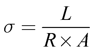
Conductivity of the membrane was determined by electrochemical impedance spectroscopy (EIS). The prepared membrane was pre-equilibrated in 1 mM NaCl. A rectangular shape membrane with known dimensions was placed in the BT-112 conductivity cell (Scribner Associates, Inc.) and the impedance of the membrane was recorded by applying an amplitude of 0.005 V over a frequency range of 1 Hz to 0.1 MHz in the CH Instrument potentiostat (model no. CHI760E) with the help of CH Instruments software uploaded in the system. The resistance measurements of the blank cell were recorded previously and normalized to evaluate the membrane's true conductivity. From the corrected impedance value, the conductivity (σ) was calculated using eqn (2).46
| |  | (2) |
where
σ is the conductivity (S cm
−1),
A is the surface area of the membrane (cm
2),
R is the resistance of the membrane (Ω) obtained from the Randles equivalent circuit simulation of the impedance spectra and
L is the distance between the electrodes in the conductivity cell (cm).
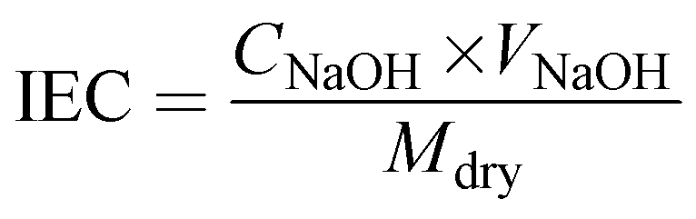
The ion exchange capacity (IEC) was obtained via the classical acid–base titration method. The membrane was completely protonated (H+) by immersion in 1 M HCl solution. After adequate washing with de-ionized water, the membrane was dipped in 1 M NaCl solution, which resulted in the exchange of H+ with sodium ions of NaCl solution. The resulting NaCl solution containing H+ ions released from the membrane was determined via titration with 0.001 M sodium hydroxide (NaOH) solution using phenolphthalein indicator. The obtained burette reading was placed in eqn (3) to calculate IEC.47
| |  | (3) |
where
Mdry represents the dry weight of the membrane, and
CNaOH and
VNaOH are the concentration and volume of NaOH consumed during the titration.
Water uptake (WU) of the membrane was estimated gravimetrically. A 4 × 4 cm membrane piece was dipped in de-ionized water for 12 h and the wet weight was noted after swabbing the excess surface adhered water using paper cloth. The dry weight of the membrane was noted after drying in a muffle furnace at 80 °C for 4 h to obtain constant weight. The wet and dry weights of the membrane were placed in eqn (4) to calculate the water uptake.48
| | 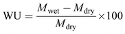 | (4) |
where
Mwet and
Mdry are the wet and dry weights of the membrane, respectively.
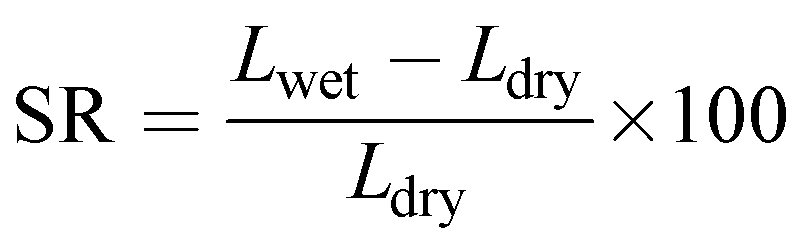
Swelling ratio (SR) was determined from the percentage difference in dimension (length) between the dried and fully hydrated membrane (eqn (5)).48
| | 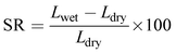 | (5) |
where,
Lwet and
Ldry are the wet and dry length of the membrane.
Water flux of the prepared membrane was determined with an Amicon Stirred cell (model no. 8400). The effective area of the cell was 14.5 cm2. The water flux of the prepared membrane was measured by exerting forced water with different applied pressures. Water permeated through the membrane was collected for 1 h for each applied pressure. The following equation was used for the determination of water flux.
| |  | (6) |
where
Jw is the water flux,
t is the time (h),
V is the volume of permeate water (L) and
A is the effective area of membrane (m
2).
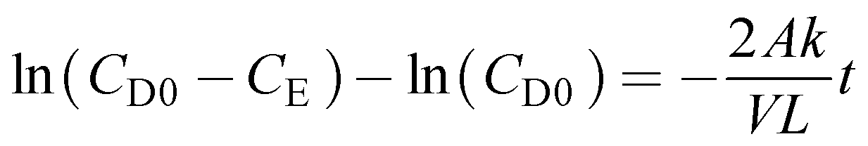
The diffusion coefficient of redox active species through the prepared membrane was calculated from the determination of change in concentration with respect to time in the enrichment compartment of a two-compartment cell (schematic and digital photograph of the two-compartment cell deployed for the present study is provided in the ESI,† Fig. S1a and b). The depletion compartment was filled with 4.0 M potassium polysulfide in 2 M KCl solution or 25 mL 0.5 M potassium ferricyanide in 2 M KCl solution. The concentration of polysulfide or ferricyanide was set as zero at the beginning of the experiment in the enrichment side. The solution in both the compartments was subjected to magnetic stirring throughout the experiment to mitigate the negative impact associated with concentration polarization. The samples were withdrawn from compartments at regular interval and the concentration of polysulfide or ferricyanide in the enrichment compartment was measured by UV-visible. For every new diffusion test, a piece of new membrane was used. It was assumed that a pseudo-steady-state condition exists in both the compartments of a two-compartment cell during diffusion test experiments, i.e., the change in concentration of polysulfide or ferricyanide in the depletion compartment was insignificant as along as their concentration in the enrichment side was low and the flux of the polysulfide or ferricyanide is constant through the separator.
The diffusion coefficient was calculated by using eqn (7)
| | 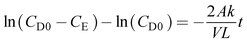 | (7) |
where
A is the membrane area (dm
2),
V is the compartment volume (dm
3),
L is the membrane thickness (dm),
CD0 is the initial concentration of polysulfide or ferricyanide in the depletion compartment (mol L
−1),
CE is the concentration of polysulfide or ferricyanide contained in the enrichment compartment (mol L
−1),
k is termed as the diffusion coefficient (dm
2 s
−1), and
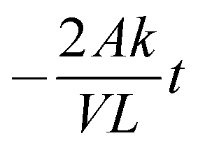
t is the time duration of the experiment (s). A plot ln(
CD0 −
CE)
vs. t should give a straight line with a slope equal to

.
2.5 Electrochemical tests
The cyclic voltammetry (CV) was tested using a CH Instruments electrochemical workstation (model no. CHI760E). The cyclic voltammograms were recorded using glassy carbon (GC) as a working electrode, platinum (Pt) wire as a counter electrode and Ag/AgCl as a reference electrode in 10 mM redox active material in 100 mM KCl as electrolyte.
2.6 Single cell performance of the polysulfide–ferricyanide redox flow battery (PSFRFB)
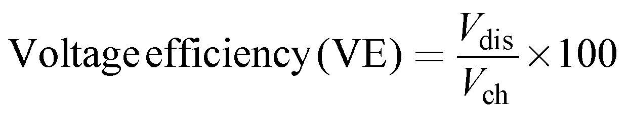
The battery performance of the prepared membrane was analyzed using a commercial flow battery cell with effective cell area 25 cm2 provided by Research Supporters India (RSI). The electrodes used in the battery were graphite electrodes and 1 mm thick carbon paper activated in concentrated nitric acid was sandwiched between the membrane and electrode to achieve zero-gap assembly (Fig. S2a and b, ESI†). The electrolyte solutions were pumped through the corresponding electrodes in air-tight silicon pipelines using small-dosing peristaltic pumps. The cell was checked for leaks before the start of the experiment. The electrolyte solutions for the positive and negative sides are 25 mL 4.0 M potassium polysulfide in 2 M KCl solution and 25 mL 0.5 M potassium ferricyanide (K3Fe(CN)6) in 2 M KCl solution, respectively. The cell was powered using a Batsol, Neware battery tester. The rate capability of the membrane was analysed by performing charge–discharge cycling experiments at different current densities. The calendar-life of the membrane was evaluated by operating the cell at 40 mA cm−2 current density for 250 charge/discharge cycles. The cut-off voltages for charging–discharging of the battery were fixed at 1.25 and 0.4 V, respectively. The polarization curve was recorded in a home-built RFB cell with an effective membrane area of 12 cm2. The cell was charged to attain 100% state of charge (SOC) at a specific current density and discharged at current densities for a fixed time. The constant voltage at each discharge current density was noted. The efficiencies were calculated as per eqn (8)–(10).49| | 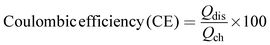 | (8) |
| |  | (9) |
| | | Energy efficiency (EE) = CE × VE | (10) |
where Qdis and Qch are the discharge and charge capacity, respectively, Vdis and Vch are the mean discharge voltage and mean charge voltage.
3. Results & discussion
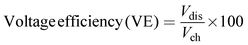
A semifluorinated cation exchange membrane was prepared by docking phenol to poly(vinylidene fluoride-co-hexafluoropropylene) (PVDF-co-HFP) using a strong base but weak nucleophile, NaH to avoid dehydrofluorination and polymer cross-linking. The resulting polymer was transformed into a membrane by the solution casting technique. The membrane was thermally annealed before functionalization with chlorosulfonic acid (Fig. 1). The attachment of phenol to PVDF-co-HFP was confirmed by 1H-NMR. As expected, the 1H-NMR spectra of the polymer showed four different types of protons, three of which belong to the docked organic moiety and one for the polymer PVDF-co-HFP. The inset structure in the 1H-NMR spectra of Fig. 2(a) is the labelled structure of the expected polymer. The aromatic protons of the attached phenol were observed in the 6.90–7.40 ppm range. A triplet at ∼6.95 ppm is attributed to the proton present in the ortho-position of the aromatic ring, while the multiplets at ∼6.90 and ∼7.3 ppm are due to the protons at the meta- and para-position. The high electronegativity of fluorine atoms resulted in deshielding of the protons present in the polymer backbone and hence found at 1.5–1.8 ppm. Fig. 2(b) is the FT-ATR spectra of T-CEM. The characteristic ether linkage peak at ∼1100 cm−1 further provided evidence of successful attachment of phenol to the polymer backbone. The peak at ∼1650 cm−1 is attributed to C–H bending of the aromatic ring.50 The presence of a sharp intense peak at ∼800 cm−1 is for C–F stretching, while the peak at ∼950 cm−1 is because of the vinylidene group of hexafluoropropylene.51 The presence of bands in the wavelength region 950–1100 cm−1 identifies the symmetric and asymmetric stretching of O![[double bond, length as m-dash]](https://www.rsc.org/images/entities/char_e001.gif) SO and OS, respectively, of the sulfonic acid group.52
SO and OS, respectively, of the sulfonic acid group.52
 |
| | Fig. 1 Reaction scheme for the synthesis of phenol-docked-PVDF-co-HFP polymer followed by thermal treatment to obtain the thermally annealed cation exchange membrane (T-CEM). | |
 |
| | Fig. 2 (a) 1H-NMR spectra of phenol-docked-PVDF-co-HFP polymer and (b) FT-ATR spectra of the T-CEM. | |
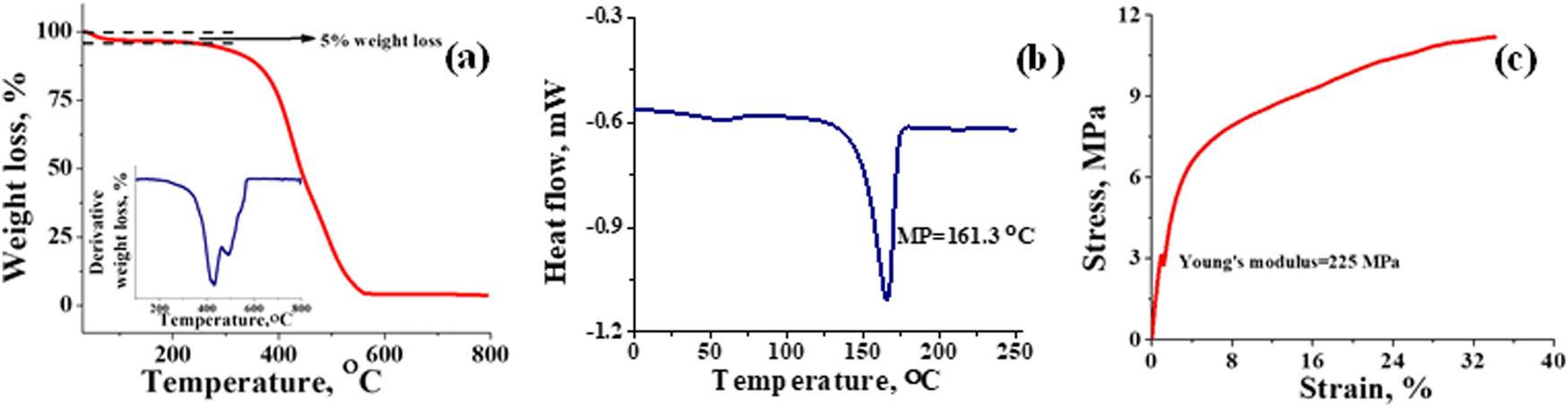
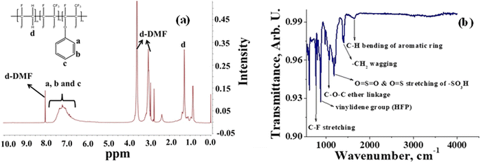
Thermal stability of T-CEM was evaluated with TGA and DSC. Fig. 3(a) depicts the weight loss in percentage for the membrane with change in temperature. From the TGA spectra, it can be seen that the membrane is thermally stable until ∼250 °C with mere 5% weight loss due to the loss of bound and trapped water. After 250 °C, the deceptive TGA spectrum is misleading, suggesting that it as a single step degradation. However, the derivative plot confirms the two-step degradation of the membrane. Weight loss in the temperature range ∼250 to ∼430 °C can be accounted for by the degradation of the sulfonic functional group and docked organic moiety, while the weight loss after ∼430 °C is due to thermal destruction of the polymer backbone. In addition, the 4% residue leftover is attributed to the carbon content present in the membrane. The DSC spectrum of the membrane (Fig. 3(b)) shows a characteristic sharp melting endothermic peak (MP) at ∼161 °C of the PVDF-co-HFP backbone. A close inspection of the spectrum reveals a tiny hump at ∼50 °C, which is due to the phase transition of the amorphous part of the polymer.53 High melting temperature for the membrane suggests its good thermal stability and potential utility over a wide range of temperatures. The Young's modulus of 225 MPa evaluated from the stress vs. strain curve (Fig. 3(c)) echoed the mechanical strength of the prepared membrane. The stress of the membrane was found to be 11 MPa while its elongation at break was 35%. In identical testing conditions, the stress and elongation at break for Nafion-117 was 22 MPa and 98% (Fig. S3, ESI†). However, the value obtained for the prepared T-CEM is appreciable for the intended flow battery application.
 |
| | Fig. 3 Thermal and mechanical stability evaluation of the T-CEM. (a) TGA spectra; inset figure: first order derivative graph. (b) Differential scanning calorimetry (DSC) spectra and (c) universal testing machine (UTM) analysis of the T-CEM. | |
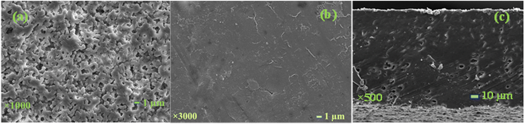
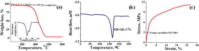
The effect of thermal treatment on the membrane surface was visualized using SEM. Fig. 4(a) is the SEM surface image of the phenol-docked-PVDF-co-HFP membrane before thermal treatment. It can be seen from the image that the membrane was microporous with interlinked crystalline morphologies.54 The characteristic symmetric particulate indicates instantaneous nucleation and development of the phenol-docked-PVDF-co-HFP crystallites55 throughout the bulk structure. The membrane bulk structure resembles that of the surface. However, no such specific morphology was observed in the surface and cross-sectional image of the thermally treated membrane (Fig. 4(b) and (c)). This is because the thermal annealing resulted in the melting of the crystallite particulate and occupancy of the void spaces on the surface. The densification of the membrane was supported by water flux data, where no water passed across the thermally treated membrane even at 5 bar applied pressure. Whereas without thermal treatment, the membrane recorded 133.3 L m−2 h−1 water flux at a mere 0.5 bar applied pressure, which is in the range of the microfiltration membrane. A dense membrane is highly rated in RFBs as it depreciates the cross contamination of redox active species and electrolyte imbalance. The cross-over of polysulfide and iron species through the membrane was evaluated in a two-compartment cell as reported in our previous studies.47,48 The diffusion coefficient (k) of polysulfide and ferricyanide across the membrane was calculated to be 4.57 × 10⁻¹¹ and 3.05 × 10⁻¹² dm2 s−1, respectively. Extremely low diffusion of ferricyanide across the membrane can be explained based on the Donnan exclusion principle.56 In solution, potassium ferricyanide (K3Fe(CN)6) dissociates as K+ and Fe(CN)63− ions, respectively, and as expected, the negative matrix of CEM does not allow Fe(CN)63− co-ions to pass through it resulting in a very low diffusion coefficient value. A similar explanation is valid for negatively charged polysulfide ions. However, a comparatively higher diffusion of polysulfide across the membrane could be due to the covalent chargeless nature of the sulfide species,57 which accelerates its diffusion across the membrane. Furthermore, in solution, polysulfide exists in different oxidation states of sulfur, with low charge density or neutral, and easily sneaks through the membrane. The diffusion coefficient values obtained for the present work was compared to the best known membranes employed for the polysulphide-based redox flow battery. Lou et al. reported a diffusion coefficient value of 1.92 × 10⁻⁹ cm2 s−1 for ferrocyanide across their best optimized potassium exchanged sulfonated polyether ether ketone (SPEEK-K) membrane.58 It was evident that with an increase in the degree of sulfonation of the polymer, there was increase in cross-over of ferricyanide species, suggesting the importance of controlled sulfonation for the desired results. A diffusion coefficient value of 3.95 × 10⁻⁹ and 6.8 × 10⁻⁸ cm2 s−1 for polysulfide across Nafion-212 and the Celgard mesoporous separator respectively has been reported.26,58 Well defined hydrophilic ion clusters present in the Nafion membranes might be the reason for the relatively fast diffusion of redox active species.59 However, we were not able to match the outstanding polysulfide blocking ability of the charge-reinforced ion selective membrane (CRIS) developed by Li and Lu.32 The polyvinylidene fluoride (PVDF)-bound carbon infiltrated Nafion membrane was able to achieve complete exclusion of polysulfide ions with no detectable sulfide species across the membrane. It is worth mentioning that the CRIS membrane is developed from expensive Nafion membranes making it economically inviable for large scale applications. Our prepared cation exchange membrane is cost-effective, the semi-fluorinated backbone of the membrane provides chemical and mechanical stability, the controlled functionalization created an ion-conducting pathway and densification by thermal treatment resulted in barricading of the redox active species.
 |
| | Fig. 4 (a) SEM surface image of the membrane before thermal treatment and (b) after thermal treatment (T-CEM) confirming its dense nature, and (c) cross-sectional SEM image after thermal treatment. | |
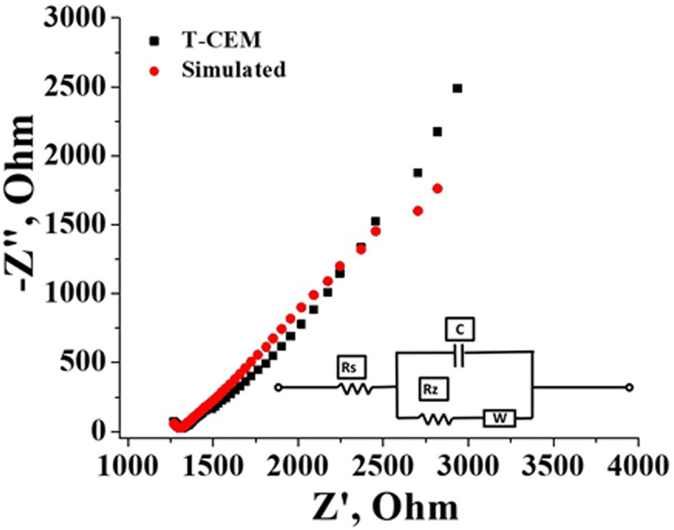
The electrochemical and physicochemical properties of the prepared membrane were evaluated by measuring its water content, swelling ratio, IEC, conductivity and counter-ion transport number. The gravimetrically estimated water content was 25.0% and the swelling ratio was a mere 10%. A low swelling ratio of the membrane identify its low electrolyte uptake capability which is beneficial in flow battery systems as there will be prevention of electrolyte transport and water osmosis due to concentration variation of the redox species across the membrane. The estimated ion exchangeable sulfonic group of the prepared membrane obtained from classic acid–base titration was found to be 1.3 meq g−1. Effective sulfonation of the membrane certainly accounted for its good conduction of ions. The conductivity of the membrane was calculated from the resistance value determined by impedance spectra presented in Fig. 5 along with the simulation data obtained with the Randles equivalent circuit. It is an equivalent electrical circuit that consists of an active electrolyte resistance (RS) in series with the parallel combination of an active charge transfer resistance (Rz), the double-layer capacitance (C) and Warburg impedance (W).60 From the spectra it can be seen that the impedance and frequency are inversely related (Fig. 5), i.e., the impedance decreases with increasing frequency and vice versa. At higher frequencies the impedance value is small due to double layer formation and charge transfer reaction. The calculated conductivity of the membrane in 1 mM NaCl solution was found to be 16.06 mS cm−1. The counter-ion transport number obtained by the membrane potential method was found to be 0.89. These values of electrochemical and physicochemical properties of the prepared membrane are compared to Nafion 117 in identical experimental conditions and summarized in Table 1. The values are comparable with Nafion-117.
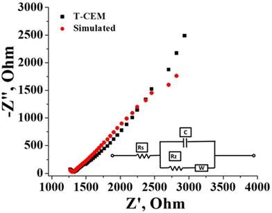 |
| | Fig. 5 Impedance spectra of the T-CEM with simulation; inset figure: Circuit diagram. | |
Table 1 Comparative electrochemical and physicochemical properties of T-CEM and Nafion 117
| Membrane code |
Water uptake (WU) (%) |
Swelling ratio (SR) (%) |
Ion exchange capacity (IEC) (meq g−1) |
Conductivity (σ) in 1 mM NaCl (mS cm−1) |
Transport no. ( 
) |
| T-CEM |
25 |
10 |
1.30 |
16.06 |
0.89 |
| Nafion 117 |
20.4 |
24 |
0.99 |
26.17 |
0.98 |
3.1 Electrochemical characteristics of potassium sulfide and potassium ferricyanide
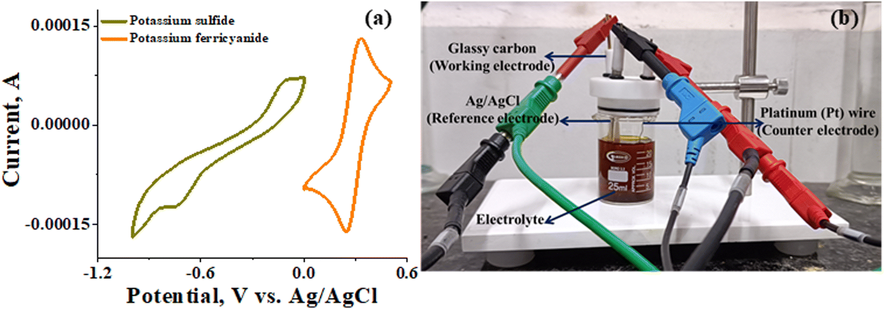
The recorded cyclic voltammogram (CV) of the redox active species and digital photograph of the three-electrode experiment assembly are shown in Fig. 6(a) and (b). As expected, the ferri/ferrocyanide redox couple showed a symmetrical voltammogram with an average redox potential of 0.285 V vs. Ag/AgCl; while the polysulfide redox couple showed asymmetrical voltammogram with an average redox potential of −0.427 V vs. Ag/AgCl. The asymmetrical nature is due to the sluggish redox kinetics and deposition of polysulfide on the electrode surface.61,62 It is the redox behaviour of S4−/2− species that has poor conductivity.63 From the voltammogram, the experimental potential difference between the two redox couples was 0.712 V. However, based on the cell reactions shown in eqn (11)–(13), the polysulfide–ferricyanide redox flow battery (PSFRFB) has a standard cell voltage of 0.91 V. The lower experimental potential difference between polysulfide and ferri/ferrocyanide may be associated with the presence of a multivalent polysulfide redox couple and the effect of salt concentration on the redox nature of ferricyanide.64| |  | (11) |
| |  | (12) |
| |  | (13) |
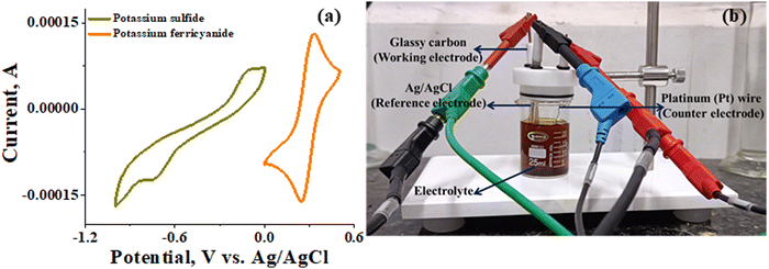 |
| | Fig. 6 (a) Cyclic voltammogram of potassium sulfide and potassium ferricyanide at 10 mV s−1 and (b) digital photograph of the three-electrode experiment assembly. | |
3.2 Single cell performance evaluation of the membrane in PSFRFB
The polysulfide–ferricyanide redox flow battery (PSFRFB) consists of highly soluble ferricyanide and polysulfide as redox active materials. Both polysulfide and ferricyanide are economically feasible and exist in abundant availability25 compared to conventional VRFBs, which employ expensive vanadium salts.9 The redox active materials for PSFRFB have high solubility in environmentally benign neutral supporting electrolytes;63 unlike VRFBs, which require sulfuric/hydrochloric acids as supporting electrolytes and even with acidic electrolytes, there are solubility constraints of vanadium salts resulting in low specific energy density and energy density for VRFBs.11 Galvanostatic charging/discharging profiles, rate performance, cycling tests and polarization curves were recorded with 4 M potassium polysulfide and 0.5 M potassium ferricyanide in 2 M KCl and presented in Fig. 7. It has been studied that polysulfide undergoes complex electrochemical reactions in both aqueous and non-aqueous electrolytes.61,62 In order to confine the negolyte side reaction between the S22− and S42−, an excess and higher concentration of the polysulfide electrolyte is preferred.63 Longevity of the membrane was tested with uninterrupted 250 charge/discharge cycles at a current density of 40 mA cm−2. The membrane demonstrated an outstanding consistency in coulombic efficiency (CE: 99.4%) and energy efficiency (EE: ∼63.0%) throughout 250 cycles, indicating the excellent stability and long calendar life. It is noteworthy that Nafion-117 exhibited lower CE of 97.7%, while EE was found to be 55.7% over 250 charge/discharge cycles in identical experimental conditions (Fig. 7(a)). The data are recorded at low current density compared to the other redox flow batteries, like the vanadium redox flow battery, aqueous organic redox flow batteries, etc.5,7,18 due to the poor voltage efficiency accounted from the sluggish kinetics of polysulfide.65 The use of electrode modification with a transition metal-based electrocatalyst is well documented in the literature for accelerating the kinetics of polysulfide.66 Another issue with the polysulfide RFBs is its poor capacity retention. This is associated with the synergetic effect of sluggish polysulfide kinetics, low conductivity of active sulfur, low utilization rate of sulphur and cross-over of soluble polysulfide intermediates across the membrane. In a continuous operation of over 250 charge/discharge cycles, the prepared membrane was able to achieve 88% capacity retention with respect to its initial capacity for the initial 100 cycles, which corresponds to 0.12% average capacity decay per cycle and for Nafion-117, the capacity retention was only 54% (Fig. 7(b)). Capacity decay observed during cycling is due to slow penetration of poorly charged sulfide intermediates through the membrane. It forms an inactive complex with ferricyanide after cross over resulting in a loss in capacity of the battery. Wei et al. were the first to report a polysulfide–ferricyanide redox flow battery.63 This study demonstrated stable battery performance with 99% CE, ∼75% VE and ∼74% EE for 100 cycles at 20 mA cm−2 current density with Nafion 117. Recently, the Lou group reported an average CE of 99.80% and EE of 90.42% over 1051 cycles at a current density of 20 mA cm−2 for a neutral polysulfide–ferrocyanide redox flow battery with an affordable SPEEK-K membrane and a highly catalytic copper sulfide-modified carbon felt electrode.58 A charge-reinforced ion selective membrane, i.e., a polyvinylidene fluoride (PVDF)-bound carbon layer on the Nafion membrane developed Li and Lu at the Chinese University of Hong Kong, is the best membrane reported for polysulfide-based redox flow batteries.32 The polysulfide iodine redox flow battery with a CRIS membrane demonstrated stable cycling over 500 continuous charge/discharge cycles with no detectable capacity decay. The rate capability of the membrane was demonstrated by recording the charge/discharge cycles at 20, 40, 50, and 60 mA cm−2 current densities. The observed CE was ∼100% at each applied current density (Fig. 7(c)). However, the EE and VE decrease linearly with an increase in current density. The obtained EE was 80, 63, 50 and 43% at 20, 40, 50 and 60 mA cm−2 current density, respectively. For the PSRFRB assembled with Nafion-117, the CE 96, 97, 98.5 and 99% at 20, 40, 50 and 60 mA cm−2 current density and EE was 74.5, 56.5, 42, and 37% for 20–60 mA cm−2 applied current density (Fig. 7(c)). Fig. 7(d) is the overlap of the charge–discharge voltage profile at different applied current densities. The voltage profile at every applied current density displayed a single voltage plateau with a high degree of reversibility indicating negligible loss of active species on cycling.32 The discharge capacity of the membrane was found to be ∼165, ∼105, ∼45 and ∼30 mA h at 20, 40, 50 and 60 mA cm−2 current density, respectively. A systematic decrease in capacity is observed with an increase in applied current density, and this is caused due to the non-zero internal cell resistance at higher current densities.67 Furthermore, at higher current densities, the electron transfer rate of redox active species is enhanced and the molecule is readily oxidized/reduced. The fast redox reaction of active molecules results in low retention time of active species in specific reduced/oxidized form and hence the migration of ions across the membrane is drastically mitigated. The reduced cross-over of ions elevates the current efficiency of the system and meanwhile the high applied current density increases the charging and discharging overpotential due to ohmic resistance and results in low voltage efficiency and capacity.
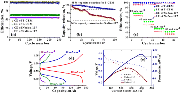 |
| | Fig. 7 PSFRFB performance of the T-CEM and state-of-the-art Nafion-117: (a) cycling test, (b) capacity retention per cycle, (c) rate capability, (d) charge–discharge voltage profile at different applied current densities for the T-CEM and (e) polarization curve. | |
The existing limitations in the cell performance can be interpreted with the help of the polarization curve.68 The polarization curve for PSFRFB employing T-CEM and Nafion-117 was obtained by plotting a graph of discharge cell voltage vs. applied current at 100% SOC. As expected, the cell depicted a typical current–voltage relationship for both the membranes (Fig. 7(e)). From the polarization curve, the peak power density of the cell with T-CEM reached 220 mW cm−2 and the experimental open circuit voltage (OCV) obtained was ∼1.03 V and the peak power density and OCV of the cell assembled with Nafion 117 was 125 mW cm−2 and 0.95 V, respectively. The initial region of the polarization curve is governed by activation losses that accounts for the minimum energy needed to surpass the activation energy associated with the charge transfer process.69 The effective current density can be enhanced by incorporating an electrode with high surface area to overcome losses due to activation polarization. The voltage drop in the second region of the polarization curve reflects the ohmic losses associated with the electrolyte and membrane resistances, the resistance from different components of the cell and the unavoidable interfacial resistance. Use of thinner membranes and highly conducting electrodes are a few techniques that can be employed to minimize the ohmic polarization.70 The concentration overvoltage losses are observed in the high current density and tail-end region of the polarization curve and are identified with mass transport and exhaustion of redox active species at the electrode surface. At high applied current densities, the supply of reactants is not able to compete with the fast electron transfer kinetics, and this eventually leads to concentration polarization.71 Optimization of the electrolyte flow rate, applied current density and concentration of redox active species can reduce the concentration polarization.
After detailed battery analysis, the PSFRFB was disassembled and the membrane was characterized to understand the stability and durability of the membrane. The membrane obtained from the cell was designated as T-CEM-A to distinguish and compare the properties with the membrane before battery performance i.e., T-CEM. There was a slight change found in IEC, water uptake, ionic conductivity and counter ion transport number of the membrane before and after battery performance (Table 2). The slight decrease in the vital electrochemical and physicochemical properties for T-CEM after battery performance can be accounted for by the irreversible sorption of polysulfide and ferro/ferri active/inactive chemical species on the membrane surface. Stable and consistent battery performance, high capacity-retention and acceptable electrochemical properties and dimensional stability of the membrane after detailed battery performance indicate the efficacy of the membrane and its best usability in PSFRFB applications.
Table 2 Electrochemical and physicochemical evaluation of the membrane (T-CEM-A) after detailed PSFRFB performance
| Membrane code |
Water uptake (WU) (%) |
Swelling ratio (SR) (%) |
Ion exchange capacity (IEC) (meq g−1) |
Conductivity (α) in 1 mM NaCl (mS cm−1) |
Transport no. ( 
) |
| T-CEM-A |
28 |
10 |
1.1 |
10.4 |
0.80 |
| T-CEM |
25 |
10 |
1.3 |
16.06 |
0.89 |
4. Conclusions
To conclude, we report a thermally annealed PVDF-co-HFP-based cation exchange membrane for neutral PSFRFBs. The thermal treatment of the membrane enables blocking of polysulfide and ferro/ferri redox active species across the membrane and meanwhile controlled sulfonation resulted in good conduction of charge carriers. The diffusion coefficient values obtained from a charge balanced two-compartment cell for polysulfide and ferricyanide across the T-CEM were 4.57 × 10⁻¹¹ and 3.05 × 10⁻¹² dm2 s−1 respectively. The PSFRFB assembled with the T-CEM delivered an excellent average coulombic efficiency of 99.4% and energy efficiency of 63% at a current density of 40 mA cm−2 over 250 continuous charge/discharge cycles. Thermal densification of the membrane resulted in 88% capacity retention of the system with an average capacity decay of 0.12% per cycle. The polarization curve experiment revealed a high-power density of 220 mW cm−2 at 400 mA cm−2 current density. Autopsy of the membrane after detailed battery performance revealed no significant losses in its electrochemical and physicochemical properties, making it an eligible candidate for large scale and long calendar life polysulfide-based redox flow batteries.
Conflicts of interest
The authors declare no competing financial interest.
Acknowledgements
RKN is grateful to the director CSIR-CSMCRI for continuous support and encouragement. RKN is thankful for the financial support of grant no. DST/TMD/MES/2K18/194(G) from Technology Mission Division, Energy and Water, DST India and Council of Scientific and Industrial Research, India (MLP-0063). RKN is also thankful for the instrumentation facilities provided by Analytical Discipline and Centralized Instrument Facility, CSIR-CSMCRI, Bhavnagar, CSIR-CSMCRI manuscript number 171/2023.
References
- S. Koohi-Fayegh and M. A. Rosen, J. Energy Storage, 2020, 27, 101047, DOI:10.1016/j.est.2019.101047.
- E. Sánchez-Díez, E. Ventosa, M. Guarnieri, A. Trovó, C. Flox, R. Marcilla, F. Soavi, P. Mazur, E. Aranzabe and R. Ferret, J. Power Sources, 2021, 481, 228804, DOI:10.1016/j.jpowsour.2020.228804.
- A. Z. Weber, M. M. Mench, J. P. Meyers, P. N. Ross, J. T. Gostick and Q. Liu, J. Appl. Electrochem., 2011, 41, 1137–1164, DOI:10.1007/s10800-011-0348-2.
- I. Iwakiri, T. Antunes, H. Almeida, J. P. Sousa, R. B. Figueira and A. Mendes, Energies, 2021, 14, 5643, DOI:10.3390/en14185643.
- P. Alotto, M. Guarnieri and F. Moro, Renewable Sustainable Energy Rev., 2014, 29, 325–335, DOI:10.1016/j.rser.2013.08.001.
- C. Zhang, L. Zhang, Y. Ding, S. Peng, X. Guo, Y. Zhao, G. He and G. Yu, Energy Storage Mater., 2018, 15, 324–350, DOI:10.1016/j.ensm.2018.06.008.
- M. Ulaganathan, V. Aravindan, Q. Yan, S. Madhavi, M. Skyllas-Kazacos and T. M. Lim, Adv. Mater. Interfaces, 2016, 3, 1500309, DOI:10.1002/admi.201500309.
- H. U. Sverdrup and A. H. Olafsdottir, Resour. Environ. Sustain., 2023, 13, 100121, DOI:10.1016/j.resenv.2023.100121.
- L. Tang, P. Leung, M. R. Mohamed, Q. Xu, S. Dai, X. Zhu, C. Flox, A. A. Shah and Q. Liao, Electrochim. Acta, 2023, 437, 41460, DOI:10.1016/j.electacta.2022.141460.
- X. Yuan, C. Song, A. Platt, N. Zhao, H. Wang, H. Li, K. Fatih and D. Jang, Int. J. Energy Res., 2019, 43, 6599–6638, DOI:10.1002/er.4607.
- Z. Huang, K. Lourenssen, J. Williams, F. Ahmadpour, R. Clemmer and S. Tasnim, J. Energy Storage, 2019, 25, 100844, DOI:10.1016/j.est.2019.100844.
- G. L. Soloveichik, Chem. Rev., 2015, 115, 11533–11558, DOI:10.1021/cr500720t.
- H. Zhang, W. Lu and X. Li, Electrochem. Energy Rev., 2019, 2, 492–506, DOI:10.1007/s41918-019-00047-1.
- A. Khor, P. Leung, M. R. Mohamed, C. Flox, Q. Xu, L. An, R. G. A. Wills, J. R. Morante and A. A. Shah, Mater. Today Energy, 2018, 8, 80–108, DOI:10.1016/j.mtener.2017.12.012.
- Z. Yuan, Y. Yin, C. Xie, H. Zhang, Y. Yao and X. Li, Adv. Mater., 2019, 31, 1902025, DOI:10.1002/adma.201902025.
- Y. Huang, S. Gu, Y. Yan and S. F. Y. Li, Curr. Opin. Chem. Eng., 2015, 8, 105–113, DOI:10.1016/j.coche.2015.04.001.
- J. Winsberg, T. Hagemann, T. Janoschka, M. D. Hager and U. S. Schubert, Angew. Chem., Int. Ed., 2017, 56, 686–711, DOI:10.1002/anie.201604925.
- Z. Li, G. Weng, Q. Zou, G. Cong and Y. Lu, Nano Energy, 2016, 30, 283–292, DOI:10.1016/j.nanoen.2016.09.043.
- L. Su, A. Badel, C. Cao, J. J. Hinricher and F. R. Brushett, Ind. Eng. Chem. Res., 2017, 56, 9783–9792, DOI:10.1021/acs.iecr.7b01476.
- Z. Li, M. S. Pan, L. Su, P. Tsai, A. F. Badel, J. M. Valle, S. L. Eiler, K. Xiang, F. R. Brushett and Y.-M. Chiang, Joule, 2017, 1, 306–327, DOI:10.1016/j.joule.2017.08.007.
- Y. Xia, M. Ouyang, V. Yufit, R. Tan, A. Regoutz, A. Wang, W. Mao, B. Chakrabarti, A. Kavei, Q. Song, A. R. Kucernak and N. P. Brandon, Nat. Commun., 2022, 13, 2388, DOI:10.1038/s41467-022-30044-w.
- W. Liu, W. Lu, H. Zhang and X. Li, Chem. – Eur. J., 2019, 25, 1649–1664, DOI:10.1002/chem.201802798.
- Y. Zhu, K. He, T. T. Tsega, N. Ali, J. Zai, S. Huang, X. Qian and Z. Chen, Sustainable Energy Fuels, 2020, 4, 2892–2899, 10.1039/C9SE01201J.
- D. Ma, B. Hu, W. Wu, X. Liu, J. Zai, C. Shu, T. T. Tsega, L. Chen, X. Qian and T. L. Liu, Nat. Commun., 2019, 10, 3367, DOI:10.1038/s41467-019-11176-y.
- Y. Long, Z. Xu, G. Wang, H. Xu, M. Yang, M. Ding, D. Yuan, C. Yan, Q. Sun, M. Liu and C. Jia, iScience, 2021, 24, 103157, DOI:10.1016/j.isci.2021.103157.
- C. Li, A. L. Ward, S. E. Doris, T. A. Pascal, D. Prendergast and B. A. Helms, Nano Lett., 2015, 15, 5724–5729, DOI:10.1021/acs.nanolett.5b02078.
- Z. Luo, Z. Chang, Y. Zhang, Z. Liu and J. Li, Int. J. Hydrogen Energy, 2010, 35, 3120–3124, DOI:10.1016/j.ijhydene.2009.09.013.
- C. Francia, V. S. Ijeri, S. Specchia and P. Spinelli, J. Power Sources, 2011, 196, 1833–1839, DOI:10.1016/j.jpowsour.2010.09.058.
- L. Gubler, Curr. Opin. Electrochem., 2019, 18, 31–36, DOI:10.1016/j.coelec.2019.08.007.
- B. G. Kim, T. H. Han and C. G. Cho, J. Nanosci. Nanotechnol., 2014, 14, 9073–9077, DOI:10.1166/jnn.2014.10087.
- S. Zhang, W. Guo, F. Yang, P. Zheng, R. Qiao and Z. Li, Batter. Supercaps, 2019, 2, 627–637, DOI:10.1002/batt.201900056.
- Z. Li and Y. Lu, Nat. Energy, 2021, 6, 517–528, DOI:10.1038/s41560-021-00804-x.
- C. Suna, J. Chena, H. Zhang, X. Hana and Q. Luo, J. Power Sources, 2010, 195, 890–897, DOI:10.1016/j.jpowsour.2009.08.041.
- T. Wang, X. Wang, A. Pendse, Y. Gao, K. Wang, C. Bae and S. Kim, J. Membr. Sci., 2021, 636, 119539, DOI:10.1016/j.memsci.2021.119539.
- S. Sreenath, P. S. Nayanthara, C. M. Pawar, M. C. Noufal and R. K. Nagarale, J. Energy Storage, 2021, 40, 102689, DOI:10.1016/j.est.2021.102689.
- D. Düerkop, H. Widdecke, C. Schilde, U. Kunz and A. Schmiemann, Membranes, 2021, 11, 214, DOI:10.3390/membranes11030214.
- J. C. Montermoso, Rubber Chem. Technol., 1961, 34, 1521–1552 CrossRef CAS.
- A. L. Logothetis, Prog. Polym. Sci., 1989, 14, 251–296 CrossRef CAS.
- Z. Cui, E. Drioli and Y. M. Lee, Prog. Polym. Sci., 2014, 39, 164–198, DOI:10.1016/j.progpolymsci.2013.07.008.
- B. S. Lalia, V. Kochkodan, R. Hashaikeh and N. Hilal, Desalination, 2013, 326, 77–95, DOI:10.1016/j.desal.2013.06.016.
- S. Sreenath, C. M. Pawar, P. Bavdane, D. Y. Nikumbe and R. K. Nagarale, Energy Adv., 2022, 1, 87, 10.1039/d1ya00059d.
- A. Mokrini, N. Raymond, K. Theberge, L. Robitaille, C. Del Rio, M. C. Ojeda, P. G. Escribano and J. L. Acosta, ECS Trans., 2010, 33, 855–865, DOI:10.1149/1.3484579.
- H. J. Oh, J. Park, S. Inceoglu, I. Villaluenga, J. L. Thelen, X. Jiang, J. E. McGrath and D. R. Paul, Polymer, 2017, 109, 106–114, DOI:10.1016/j.polymer.2016.12.035.
- S. Mbarek, N. El Kissi, Z. Baccouch and C. Iojoiu, Polym. Bull., 2019, 76, 1151–1166, DOI:10.1007/s00289-018-2427-6.
- R. K. Nagarale, G. S. Gohil and V. K. Shahi, Adv. Colloid Interface Sci., 2006, 119, 97–130, DOI:10.1016/j.cis.2005.09.005.
- M. Y. Kariduraganavar, R. K. Nagarale, A. A. Kittur and S. S. Kulkarni, Desalination, 2006, 197, 225–246, DOI:10.1016/j.desal.2006.01.019.
- P. P. Bavdane, S. Sreenath, D. Y. Nikumbe, C. M. Pawar, M. C. Kuzhiyil and R. K. Nagarale, ACS Appl. Energy Mater., 2022, 5, 13189–13199, DOI:10.1021/acsaem.2c01080.
- S. Sreenath, P. S. Nayanthara, C. M. Pawar, D. Y. Nikumbe, B. Bhatt, J. C. Chaudhari and R. K. Nagarale, ACS Appl. Energy Mater., 2022, 5, 13661–13671, DOI:10.1021/acsaem.2c02328.
- S. Sreenath, N. K. Sharma and R. K. Nagarale, RSC Adv., 2020, 10, 44824, 10.1039/d0ra08316j.
- S. Das, P. Kumar, K. Dutta and P. P. Kundu, Appl. Energy, 2014, 113, 169–177, DOI:10.1016/j.apenergy.2013.07.030.
- M. A. Gebreyesus, Y. Purushotham and J. SivaKumar, Heliyon, 2016, 2, e00134, DOI:10.1016/j.heliyon.2016.e00134.
- K. Polat, Appl. Phys. A: Mater. Sci. Process., 2020, 126, 497, DOI:10.1007/s00339-020-03698-w.
- L. F. Malmonge, J. A. Malmonge and W. K. Sakamoto, Mater. Res., 2003, 6, 469–473, DOI:10.1590/S1516-14392003000400007.
- A. Gugliuzza and E. Drioli, J. Membr. Sci., 2007, 300, 51–62, DOI:10.1016/j.memsci.2007.05.004.
- W. Ma, H. Yuan and X. Wang, Membranes, 2014, 4, 243–256, DOI:10.3390/membranes4020243.
- S. Sarkar, A. K. SenGupta and P. Prakash, Environ. Sci. Technol., 2010, 44, 1161–1166, DOI:10.1021/es9024029.
- R. Steudel and Y. Steudel, Chem. – Eur. J., 2013, 19, 3162–3176, DOI:10.1002/chem.201203397.
- X. Lou, H. Fu, J. Xu, Y. Long, S. Yan, H. Zou, B. Lu, M. He, M. Ding, X. Zhu and C. Jia, Energy Mater. Adv., 2022, 2022, 9865618, DOI:10.34133/2022/9865618.
- P. Xiong, L. Zhang, Y. Chen, S. Peng and G. Yu, Angew. Chem., Int. Ed., 2021, 60, 2, DOI:10.1002/anie.202105619.
- J. C. Marrero, A. d Souza Gomes, W. S. Hui, J. C. D. Filho and V. S. de Oliveira, Polímeros, 2017, 27, DOI:10.1590/0104-1428.07216.
- H. Pan, X. Wei, W. A. Henderson, Y. Shao, J. Chen, P. Bhattacharya, J. Xiao and J. Liu, Adv. Energy Mater., 2015, 5, 1500113, DOI:10.1002/aenm.201500113.
- M. Behm and D. Simonsson, J. Appl. Electrochem., 1997, 27, 507, DOI:10.1023/A:1018486309601.
- X. Wei, G. Xia, B. Kirby, E. Thomsen, B. Li, Z. Nie, G. G. Graff, J. Liu, V. Sprenkle and W. Wang, J. Electrochem. Soc., 2016, 163, A5150, DOI:10.1149/2.0221601jes.
- L. Suo, O. Borodin, T. Gao, M. Olguin, J. Ho, X. Fan, C. Luo, C. Wang and K. Xu, Science, 2015, 350, 938, DOI:10.1126/science.aab1595.
- H. Wang, W. Zhang, J. Xu and Z. Guo, Adv. Funct. Mater., 2018, 1707520, 1–14, DOI:10.1002/adfm.201707520.
- J. Wu, T. Ye, Y. Wang, P. Yang, Q. Wang, W. Kuang, X. Chen, G. Duan, L. Yu, Z. Jin, J. Qin and Y. Lei, ACS Nano, 2022, 16, 15734–15759, DOI:10.1021/acsnano.2c08581.
- A. Khataee, E. Drazevic, J. Catalano and A. Bentien, J. Electrochem. Soc., 2018, 165, A3918–A3924, DOI:10.1149/2.0681816jes.
- P. C. Ghimire, A. Bhattarai, T. M. Lim, N. Wai, M. Skyllas-Kazacos and Q. Yan, Batteries, 2021, 7, 53, DOI:10.3390/batteries7030053.
- D. Aaron, Z. Tang, A. B. Papandrew and T. A. Zawodzinski, J. Appl. Electrochem., 2011, 41, 1175–1182, DOI:10.1007/s10800-011-0335-7.
- K. J. Kim, M. Park, Y. Kim, J. H. Kim, S. X. Doub and M. Skyllas-Kazacos, J. Mater. Chem. A, 2015, 3, 16913, 10.1039/c5ta02613j.
- K. J. Yoon, W. Huang, G. Ye, S. Gopalan, U. B. Pal and D. A. Seccombe Jr., J. Electrochem. Soc., 2007, 4, B389–B395, DOI:10.1149/1.2436610.
|
| This journal is © The Royal Society of Chemistry 2024 |
Click here to see how this site uses Cookies. View our privacy policy here. 
 Open Access Article
 This Open Access Article is licensed under a Creative Commons Attribution-Non Commercial 3.0 Unported Licence
 cd and
Rajaram K.
Nagarale
cd and
Rajaram K.
Nagarale
 is the sodium ion transport number in the membrane phase.


 .
.