 Open Access Article
Solid–liquid–solid mediated artificial SEI coated stable lithium and high-sulfur percentage SPAN for high performance Li–S batteries†
Krishna
Sarode‡
a,
Taber
Yim‡
 a,
Rhyz
Pereira
a,
Neal
Cardoza
a and
Vibha
Kalra
a,
Rhyz
Pereira
a,
Neal
Cardoza
a and
Vibha
Kalra
 *ab
*ab
aDepartment of Chemical and Biological Engineering, Drexel University, Philadelphia, PA 19104, USA
bSmith School of Chemical and Biomolecular Engineering, Cornell University, Ithaca, NY, USA. E-mail: vk69@cornell.edu
First published on 23rd January 2024
Abstract
Lithium–sulfur batteries (LSBs) are a next generation battery that are an attractive alternative to lithium-ion batteries. Although, LSBs are conventionally reliant on ether electrolytes that promote the unwanted polysulfide shuttling effect and lead to safety concerns due to low flash points. Another major issue is the instability of lithium metal at the anode. These two issues hinder the scaling up of this chemistry from coin cells to pouch cells. Herein, we present a novel synthesis method to produce sulfurized polyacrylonitrile (SPAN), a material that can avoid polysulfide formation and is compatible with carbonate electrolytes. Our synthesis method results in an 18% increase in sulfur content, compared to a traditional synthesis method. The new synthesis method also creates smaller cathode agglomerations which improves cell performance. We also studied the influence of a polymeric artificial SEI on the stability of the lithium metal anode. Using postmortem XPS, we found an increase in LiF with this anode treatment. We combined these materials in a Li-SPAN pouch cell to investigate their performance at a larger scale and found it to be electrochemically stable in a commercial carbonate electrolyte. It yielded an initial stable capacity of 1068 mA h gsulfur−1 (572 mA h gSPAN−1) with a capacity retention of 82% after 200 cycles. This treated pouch cell lasted nearly five times longer than a conventional pouch cell with no lithium treatment.
1. Introduction
Lithium–sulfur batteries (LSBs) are a promising next generation energy storage system. They have a high theoretical gravimetric energy density at 2500 W h kg−1, with a practical energy density between 250 and 500 W h kg−1.1 Although this is lower than its theoretical mark, it is two to three times higher than that of current commercial, state-of-the-art Li-ion batteries (LIBs), which have a practical capacity in the range of 150 to 220 W h kg−1.2 However, LSBs conventionally use ether electrolytes that have a series of challenges. One critical issue is the high solubility of intermediate lithium polysulfides that are generated during discharge. They can dissolve in the ether electrolyte and shuttle to the anode, corroding the lithium metal and depleting the active material.3 Ether-based solvents also have low flash points and are highly volatile, limiting their battery application at elevated temperatures. Therefore, the practical use of an ether-based electrolyte poses safety concerns.4These problems associated with ether electrolytes can be alleviated by using a carbonate electrolyte. Current LIBs employ commercialized carbonate electrolytes due to their wide range of operating temperatures and voltage window stability.5,6 Thus, replacing the ether electrolyte with a carbonate electrolyte can help realize safe and stable LSBs. Sulfurized polyacrylonitrile (SPAN) is attractive as a Li–S cathode because it enables the use of commercial carbonate electrolytes, due to the strong covalent bonding of sulfur to a polymer host.7 This avoids the formation of soluble polysulfides during cycling. However, SPAN generally contains a limited amount of sulfur, around 40–45 wt% of the material.8–11 This low sulfur loading is a drawback to achieving high energy density LSBs in carbonate electrolytes. To achieve the practical application of LSBs in carbonate electrolytes, there is a need for a cathode with a higher sulfur percentage. In this work, we synthesized SPAN with a sulfur percentage of 53.62%.
Another significant challenge in the application of LSBs is the instability of lithium metal, especially in carbonate electrolytes. Lithium degrades rapidly in carbonate electrolytes due to dendrite and dead lithium formation. This leads to poor electrochemical performance.12,13 The dead lithium forms mossy structures that are then covered by a solid electrolyte interface (SEI), separating them from the current collector. Moreover, the porous nature of the dead lithium layer increases the consumption and degradation of the electrolyte due to an increase in side reactions. Ultimately, this results in rapid capacity fade.14,15 There are many strategies to minimize dead lithium formation and maintain the electrical contact between deposited lithium and the current collector.16 Methods that have been studied in literature include using a high concentration electrolyte,17 employing a fluorinated electrolyte,18 passivating the lithium metal surface with electrolyte additives,19 3D architectures for reducing local current density and directing Li-ion deposition,20 and imparting high external mechanical pressure to promote smooth deposition Li–metal.21 One of the most successful strategies for preventing and minimizing dead lithium formation is a lithium fluoride (LiF) coating on the lithium metal due to its high surface energy an low lithium-ion diffusion resistance.22 In early works, LiF containing SEIs were formed by adding fluorinated compounds, like hydrofluoric acid, into the electrolyte.23 Since then, other methods have also been explored. Fan et al. made an artificial LiF based SEI on lithium metal by sputter deposition.24 Zhao et al. heated a fluoropolymer (CYTOP) to generate fluorine gas that reacted with lithium metal, making an artificial LiF layer.25 Lang et al. coated lithium metal with a solution of dissolved PVDF in DMF, during which PVDF defluorinated and formed an LiF coating.26 Sun et al. also created an in situ LiF and defluorinated polymer composite coating on lithium metal using a polytetrafluoroethylene (PTFE) film and roll pressing it on to lithium metal.27 These lithium treatments are crucial for scaling up LSBs to pouch cell level.
Although the first Li–S pouch cell publication was nearly a decade ago in 2014, challenges persist and lithium instability is still a main cause for pouch cell failure hindering the long term cyclability for Li–S pouch cells.28,29 Furthermore, there have not been many Li-SPAN pouch cell studies published within the last few years. Most recently, Ma et al. used thin lithium in a Li-SPAN pouch cell under lean electrolyte conditions and achieved 50 cycles.30 Shen et al. achieved 100 cycles in a pouch cell with an ultrathin lithium anode and an SPAN (40 wt% S) cathode by tailoring the electrolyte.31 Duan et al. made an Ah-level pouch cell possible by using a SPAN cathode and lithium-tin alloy anode. However, they noted that the SPAN and pure lithium anode failed after 40 cycles.32 Wang et al. used 2D nanosheets of SPAN (45 wt% S) to achieve 100 cycles in a Li-SPAN pouch cell. Cai et al. studied electrolyte thermal stability and were able to cycle a Li-SPAN pouch cell 50 times using their electrolyte.33 Li et al. employed a solid polymer electrolyte and created a flexible Li-SPAN (50.2 wt% S) pouch cell that cycled 20 times in a bent state. In this work, we also fabricate Li-SPAN pouch cells that can achieve 200 cycles with a high sulfur content SPAN cathode.
Herein, we demonstrate a SPAN synthesis method to achieve a high sulfur content SPAN material with 53.62% sulfur that enables a higher energy density battery. We also show a method to create a protective LiF SEI layer for the lithium metal anode using poly(vinylidene fluoride)-co-hexafluoropropylene (PVDF-HFP). PVDF-HFP is highly compatible with lithium metal due to its electrochemical stability, elastic modulus to support lithium volume changes, and ability to facilitate LiF formation.34,35 Additionally, we use a roll pressing method to ensure a compact LiF lithium protection layer. We combine this treated lithium anode with the high sulfur content SPAN cathode at the pouch cell level to create a battery system with improved stability and energy density. This work represents a step towards the development of more stable Li-SPAN pouch cells with higher energy density and compatibility with carbonate electrolytes.
2. Experimental
2.1. Materials
Polyacrylonitrile (PAN, Mw = 150![[thin space (1/6-em)]](https://www.rsc.org/images/entities/char_2009.gif) 000 g mol−1), ethanol (99%), N,N dimethyl formamide (DMF, 99.8%), polyvinylidene fluoride-co-hexafluoro propylene (PVDF-HFP, MW ∼400
000 g mol−1), ethanol (99%), N,N dimethyl formamide (DMF, 99.8%), polyvinylidene fluoride-co-hexafluoro propylene (PVDF-HFP, MW ∼400![[thin space (1/6-em)]](https://www.rsc.org/images/entities/char_2009.gif) 000 and MN ∼130
000 and MN ∼130![[thin space (1/6-em)]](https://www.rsc.org/images/entities/char_2009.gif) 000), and 1 M lithium hexafluoro phosphate in ethylene carbonate and diethyl carbonate (1 M LiPF6 in EC
000), and 1 M lithium hexafluoro phosphate in ethylene carbonate and diethyl carbonate (1 M LiPF6 in EC![[thin space (1/6-em)]](https://www.rsc.org/images/entities/char_2009.gif) :
:![[thin space (1/6-em)]](https://www.rsc.org/images/entities/char_2009.gif) DEC 1
DEC 1![[thin space (1/6-em)]](https://www.rsc.org/images/entities/char_2009.gif) :
:![[thin space (1/6-em)]](https://www.rsc.org/images/entities/char_2009.gif) 1, H2O <6 ppm and O2 <1 ppm) were purchased from Sigma Aldrich. Cobalt chloride (CoCl2) was purchased from Acros Organics. Carbon black (Super P 99+% metals basis), sulfur (99.5%, sublimed, 100 mesh), lithium (99.9%, 750 μm thick), sodium carboxy methyl cellulose (NaCMC) were purchased from Alfa Aesar. Styrene butadiene rubber (SBR, 50 ± 2 wt% in DI water) and polyvinylidene fluoride was purchased from MTI corporation. Acetone (99.5%) was purchased from VWR. Commercial battery separators (tri-layer, Celgard 2325, f = 19 mm) were purchased from Celgard. Aluminum laminated pouch cell foil was purchased from TMAX.
1, H2O <6 ppm and O2 <1 ppm) were purchased from Sigma Aldrich. Cobalt chloride (CoCl2) was purchased from Acros Organics. Carbon black (Super P 99+% metals basis), sulfur (99.5%, sublimed, 100 mesh), lithium (99.9%, 750 μm thick), sodium carboxy methyl cellulose (NaCMC) were purchased from Alfa Aesar. Styrene butadiene rubber (SBR, 50 ± 2 wt% in DI water) and polyvinylidene fluoride was purchased from MTI corporation. Acetone (99.5%) was purchased from VWR. Commercial battery separators (tri-layer, Celgard 2325, f = 19 mm) were purchased from Celgard. Aluminum laminated pouch cell foil was purchased from TMAX.
2.2. SPAN cathode synthesis
The SPAN material was synthesized by mixing PAN and sulfur (S) (1![[thin space (1/6-em)]](https://www.rsc.org/images/entities/char_2009.gif) :
:![[thin space (1/6-em)]](https://www.rsc.org/images/entities/char_2009.gif) 4 by wt%) followed by wet ball milling for 12 hours at 400 rpm using ethanol as the solvent. The mixture was then dried at 50 °C in a vacuum oven (TMAX) for 6 hours. Finally, it was heat treated in a tubular furnace (Nabertherm) at 350 °C for 4 hours under constant nitrogen gas flow. In this work, we studied two synthesis methods, open and closed. For open synthesis, the PAN/S mixture was placed in an open top ceramic boat. For closed synthesis, the PAN/S mixture was wet ball milled with 2 wt% CoCl2 during that step of the process. The mixture was then placed in the alumina ceramic boat closed with an alumina plate followed by wrapping in aluminum foil. PAN was carbonized at 350 °C under constant nitrogen flow to create a baseline material.
4 by wt%) followed by wet ball milling for 12 hours at 400 rpm using ethanol as the solvent. The mixture was then dried at 50 °C in a vacuum oven (TMAX) for 6 hours. Finally, it was heat treated in a tubular furnace (Nabertherm) at 350 °C for 4 hours under constant nitrogen gas flow. In this work, we studied two synthesis methods, open and closed. For open synthesis, the PAN/S mixture was placed in an open top ceramic boat. For closed synthesis, the PAN/S mixture was wet ball milled with 2 wt% CoCl2 during that step of the process. The mixture was then placed in the alumina ceramic boat closed with an alumina plate followed by wrapping in aluminum foil. PAN was carbonized at 350 °C under constant nitrogen flow to create a baseline material.
Cathodes were fabricated using the synthesized SPAN material. The cathode materials were 80 wt% of SPAN, 10 wt% carbon black, and 10 wt% NaCMC-SBR binder. First, the SPAN and carbon black was mixed in a Flacktek planetary mixer for 5 minutes. NaCMC-SBR binder was dissolved in water in the Flacktek mixer. The SPAN and carbon black mixture was then added to the binder solution to complete the electrode slurry and mixed in the Flacktek at 2500 rpm for 1 hour in intervals of 15 minutes followed by 5 minutes resting. The electrode slurry was then coated onto a carbon coated aluminum foil using an applicator with a height of 250 microns followed by drying in oven at 50 °C for 12 hours.
2.3. Lithium anode treatments
This work studied the use of a lithium anode treatment to create an artificial SEI. The lithium treatment process was performed in a glovebox (MBraun LABstar) with O2 and H2O levels at <1 ppm. First, PVDF-HFP was dissolved and stirred in acetone. A film was made by coating this solution on a glass plate using a doctor blade. The film was dried in air for 5 minutes. Once dry, it was peeled off the glass and transferred to the glovebox. The thickness of the film obtained was in the range of 8–10 μm. The film was placed on the lithium metal and roll pressed to the surface. Then, a polypropylene separator soaked with DMF solvent was placed on the PVDF-HFP coated lithium metal and roll pressed again. This process resulted in a partial re-dissolution of the solid PVDF-HFP polymer in DMF, which occurred on the lithium metal. After the second roll pressing step, the anode was rested for 5 minutes as the excess DMF evaporated. After this time, a solid film on the lithium formed again. We refer to this as a solid–liquid–solid conversion process.2.4. LiF formation mechanism
Similar to previous works, the use of PVDF-HFP and DMF in direct contact with lithium creates an environment where LiF can form. The use of DMF is crucial in this process, as it can donate electron pairs to facilitate the defluorination of the polymer to form LiF and partially defluorinated polyene, as illustrated in eqn (1).22,26 We also believe the addition of roll pressing facilitates a more uniform polymer layer with LiF embedded in the matrix.| PVDF-HFP + Li → PVDF-HFP-Olefin + LiF + H2 | (1) |
2.5. Coin cell fabrication
The dried SPAN slurry electrodes were cut using a die (f = 0.5 inches, 12.7 mm) to form disk electrodes. The electrodes were then transferred to an argon-filled glovebox (MBraun LABstar, O2 and H2O levels <1 ppm). Li-SPAN cells were assembled in a CR2032 coin cell format (MTI and Xiamen TMAX Battery Equipments, China) using the SPAN cathodes, lithium disk anodes (Xiamen TMAX Battery Equipment's; f = 15.6 mm, 450 mm thick), a Celgard 2325 separator, one stainless steel spring, two stainless steel spacers, and carbonate electrolyte. The electrolyte was 1 M LiPF6 in EC![[thin space (1/6-em)]](https://www.rsc.org/images/entities/char_2009.gif) :
:![[thin space (1/6-em)]](https://www.rsc.org/images/entities/char_2009.gif) DEC 1
DEC 1![[thin space (1/6-em)]](https://www.rsc.org/images/entities/char_2009.gif) :
:![[thin space (1/6-em)]](https://www.rsc.org/images/entities/char_2009.gif) 1 added at an E/S ratio of 8. The assembled coin cells were rested at their open circuit voltage for 12 hours to equilibrate them before performing electrochemical experiments at room temperature.
1 added at an E/S ratio of 8. The assembled coin cells were rested at their open circuit voltage for 12 hours to equilibrate them before performing electrochemical experiments at room temperature.
2.6. Pouch cell fabrication
SPAN cathodes were punched with dimensions 57 mm × 44 mm using a die cutter (MSK-T-11, MTI, USA). In the glovebox, lithium was rolled to a thickness of 200–300 μm at 0.33 rpm, rolled onto a copper current collector, and then punched into a 58 mm × 45 mm cathode with a die cutter (MST-T-11, MTI, USA). The cathode and anode were welded with aluminum and nickel tabs (3 mm length), respectively. The tabs were welded with an ultrasonic metal welder (TMAX, VS-40A), at 40 KHz frequency, a delay time of 0.2 s, and welding time of 0.15 s for aluminum tabs and 0.45 s nickel tabs. The anode and cathode were placed between a Celgard 2325 separator and 1 M LiPF6 in EC![[thin space (1/6-em)]](https://www.rsc.org/images/entities/char_2009.gif) :
:![[thin space (1/6-em)]](https://www.rsc.org/images/entities/char_2009.gif) DEC 1
DEC 1![[thin space (1/6-em)]](https://www.rsc.org/images/entities/char_2009.gif) :
:![[thin space (1/6-em)]](https://www.rsc.org/images/entities/char_2009.gif) 1 electrolyte was added at an E/S ratio of 5. The pouch was sealed with a 3-in-1 heat pouch sealer (TMAX, TF-200) inside the glove box with a 95 kPa vacuum, 4.0 s sealing time at 180 °C, and 6.0 s degas time.
1 electrolyte was added at an E/S ratio of 5. The pouch was sealed with a 3-in-1 heat pouch sealer (TMAX, TF-200) inside the glove box with a 95 kPa vacuum, 4.0 s sealing time at 180 °C, and 6.0 s degas time.
2.7. Material characterization
The morphological analysis of the materials was conducted using a scanning electron microscope (SEM, Zeiss Supra 50VP, Germany) with an in-lens detector and a 30 mm aperture. Particle size was estimated using the Image-J software. To analyze the surface elemental composition, energy dispersive X-ray spectroscopy (EDS, Oxford Instruments) was used in secondary electron-detection mode. To analyze SPAN material elemental composition, elemental analysis was performed at the Drexel Academy of Natural Science – Patrick Center for Environmental Research using a CHNOS analyzer (Elementar Americas Isoprime100 coupled with a Vario Cube). Each CHNOS elemental analysis sample was run in duplicate, averaged, and checked against a standard. Dynamic light scattering (DLS, Brookhaven Nanobrook Omni) was used to observe particle and agglomeration size in the SPAN material. The chemical environment of material surfaces was analyzed with X-ray photoelectron spectroscopy (XPS, PHI VersaProbe 5000). To collect XPS spectra, samples were irradiated with Al-Kα X-rays, with spot sizes of 200 mm and pass energy of 23.5 eV. CasaXPS (version 23.19PR1.0) software was used for spectra analyses. The XPS spectra were calibrated by setting the valence edge to zero. The background was determined using the Shirley algorithm, which is a built-in function in the CasaXPS software. The infrared spectra of the samples were collected using a Fourier transform infrared spectrometer (FTIR, Nicolet iS50, Thermo-Fisher Scientific) using an extended range diamond attenuated total reflection (ATR) accessory. A deuterated triglycine sulfate (DTGS) was used with a resolution of 64 scans per spectrum at 8 cm−1 and all the spectra were further corrected with background, baseline correction and advanced ATR correction in the Thermo Scientific Omnic software package.2.8. Electrochemical characterization
Cyclic voltammetry (CV) was performed at a scan rate of 0.5 mV s−1 between 1.0 and 3.0 V with respect to Li/Li+ and electrochemical impedance spectroscopy (EIS) was conducted from 1 MHz to 100 mHz with a 10 mV potential amplitude. Both techniques were performed on a Biologic VMP3 potentiostat. Prolonged galvanostatic cycling tests were carried out with a battery cycler (Neware BTS 4000) at different C-rates (where 1C = 654 mA h g−1SPAN36 or 1C = 1672 mA h g−1sulfur) between 1.0 and 3.0 V.3. Results and discussion
3.1. SPAN characterization and performance
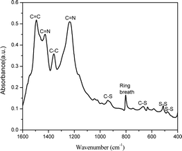
Fig. 1 shows the FTIR spectrum for SPAN synthesized in the closed system. The peaks at 477 cm−1 and 511 cm−1 correspond to S–S stretching37 and the peaks at 668 cm−1 and 936 cm−1 are assigned to C–S stretching.38,39 The peak at 803 cm−1 indicates the formation of a hexahydric ring.40 The peak at 1495 cm−1 is associated with C![[double bond, length as m-dash]](https://www.rsc.org/images/entities/char_e001.gif) C stretching and the peak at 1359 cm−1 is associated with C–C bond deformation.39 The peaks at 1427 cm−1 and 1235 cm−1 correspond to C
C stretching and the peak at 1359 cm−1 is associated with C–C bond deformation.39 The peaks at 1427 cm−1 and 1235 cm−1 correspond to C![[double bond, length as m-dash]](https://www.rsc.org/images/entities/char_e001.gif) N asymmetric stretching. The presence of C
N asymmetric stretching. The presence of C![[double bond, length as m-dash]](https://www.rsc.org/images/entities/char_e001.gif) N stretching confirms the opening of the nitrile group in PAN and the aromatization of the aliphatic PAN to a polyaromatic system.41 Presence of C–S stretching confirms the sulfurization of the material.9
N stretching confirms the opening of the nitrile group in PAN and the aromatization of the aliphatic PAN to a polyaromatic system.41 Presence of C–S stretching confirms the sulfurization of the material.9
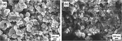
Fig. 2a shows the SPAN material synthesized in the closed system and Fig. 2b shows SPAN material synthesized in the traditional open system. In the open system, we hypothesize that sulfur is continually lost as it is converted to H2S and carried away by the constant nitrogen flow. This would decrease the sulfur content in the final SPAN material. The open system also has more agglomerations that range up to 350 nm or more (Fig. S1, ESI†), with regions of the SEM images showing more densely packed material. These large agglomerations are not desirable for the cathode active material, as it represents an increase in the charge transfer resistance and overall resistance.42 This is due to the shielding effect of insulating sulfur particles on each other and the reduction in surface area. Conversely, in the closed system, the particles seem to have smaller agglomerations compared to the open system. Our hypothesis for this change in morphology is that the closed system traps hydrogen sulfide (H2S) gas that is generated during the synthesis. By trapping the gas in the synthesis vessel, we hypothesize that the system comes to an equilibrium system pressure that hinders the formation of larger agglomerations. The closed system also preserves more sulfur for the synthesis. By increasing the available sulfur in the reaction system, we achieved a higher sulfur content SPAN material. Using CHNOS elemental analysis, we found that SPAN synthesized in a closed system contained 53.62% sulfur compared to 45.30% when synthesized in an open system. This represents an 18% increase in sulfur content, bringing it near the current upper limit of sulfur content in SPAN.43
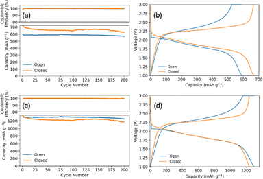
Fig. 3a compares the cycling capacity for a coin cell with SPAN synthesized in an open and closed system. The coin cell with open synthesis SPAN had an initial capacity of 587 mA h g−1SPAN and a capacity of 567 mA h g−1SPAN after 200 cycles, cycling at a C/2SPAN rate (rate is with respect to the theoretical capacity of SPAN). SPAN synthesized in a closed system had an initial capacity of 697 mA h gSPAN−1 and 627 mA h gSPAN−1 after 200 cycles, demonstrating an improved capacity and energy density. Fig. 3b shows the corresponding voltage profiles from the 50th cycle of the galvanostatic cycling test. It shows typical single plateau behavior for SPAN cathodes in carbonate electrolyte, indicating a direct solid–solid phase transition of elemental sulfur to Li2S.44 We note that the initial capacities are higher than the theoretical capacity of SPAN because the theoretical capacity was determined for SPAN material with a lower sulfur content. For this reason, we also standardize the capacity data with respect to the mass of sulfur. Fig. 3c shows the converted capacities from Fig. 3a. SPAN synthesized in the open system had an initial capacity of 1295 mA h gSulfur−1 and 1253 mA h gsulfur−1 after 200 cycles cycling at a C/3sulfur rate (rate is with respect to the theoretical capacity of sulfur). SPAN synthesized in closed system shows an initial capacity of 1301 mA h gsulfur−1 and 1170 mA h gsulfur−1 after 200 cycles. Fig. 3d again shows voltage profiles for the 50th cycle with typical single plateau behavior. When plotting with respect to sulfur, the capacities of the open and closed coin cells collapse to similar values. This is because the specific capacity is with respect to sulfur mass, rather than SPAN mass. When plotting with respect to SPAN mass, the specific capacity achieved is higher per mass in the closed system due to the increase in sulfur content. This supports our hypothesis that the increase in specific capacity using closed system SPAN was largely due to the higher sulfur content. Therefore, with the closed synthesis, a more energy dense battery can be achieved.
3.2. Lithium treatments
Fig. 4 shows the FTIR spectrum of the PVDF-HFP![[thin space (1/6-em)]](https://www.rsc.org/images/entities/char_2009.gif) :
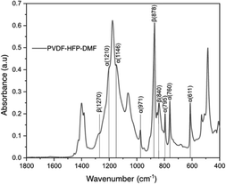
:![[thin space (1/6-em)]](https://www.rsc.org/images/entities/char_2009.gif) DMF coating on lithium metal. In our study, we find this treatment provided stability for the lithium metal anode. The vibrational peaks observed at 611, 760, 795, 1146, 1210
DMF coating on lithium metal. In our study, we find this treatment provided stability for the lithium metal anode. The vibrational peaks observed at 611, 760, 795, 1146, 1210![[thin space (1/6-em)]](https://www.rsc.org/images/entities/char_2009.gif) cm−1 are due to the α-phase of PVDF-HFP.45–47 The peaks at 1270, 840, 878 cm−1 correspond to the β-phase.48 The peak at 1400 cm−1 corresponds to CH2 bonds and the peak near 750 cm−1 corresponds to the CF2 dipole of PVDF-HFP.49 While we observe these characteristic peaks, the FTIR spectrum of the lithium metal surface coated with PVDF-HFP
cm−1 are due to the α-phase of PVDF-HFP.45–47 The peaks at 1270, 840, 878 cm−1 correspond to the β-phase.48 The peak at 1400 cm−1 corresponds to CH2 bonds and the peak near 750 cm−1 corresponds to the CF2 dipole of PVDF-HFP.49 While we observe these characteristic peaks, the FTIR spectrum of the lithium metal surface coated with PVDF-HFP![[thin space (1/6-em)]](https://www.rsc.org/images/entities/char_2009.gif) :
:![[thin space (1/6-em)]](https://www.rsc.org/images/entities/char_2009.gif) DMF does not show a polyene peak at 1650 cm−1.26 This peak would be present if there was a complete defluorination of the polymer while forming LiF. Instead, we hypothesize that there is a partial defluorination of PVDF-HFP during this treatment reaction and the absence of the polyene peak is likely due to a masking effect from unreacted PVDF-HFP. Nevertheless, we believe that this partial defluorination is beneficial due to the possible retention of the elastic moduli from polymer which could help mitigate the lithium volume change during cycling.
DMF does not show a polyene peak at 1650 cm−1.26 This peak would be present if there was a complete defluorination of the polymer while forming LiF. Instead, we hypothesize that there is a partial defluorination of PVDF-HFP during this treatment reaction and the absence of the polyene peak is likely due to a masking effect from unreacted PVDF-HFP. Nevertheless, we believe that this partial defluorination is beneficial due to the possible retention of the elastic moduli from polymer which could help mitigate the lithium volume change during cycling.
The morphology of the lithium metal anode coated with PVDF-HFP![[thin space (1/6-em)]](https://www.rsc.org/images/entities/char_2009.gif) :
:![[thin space (1/6-em)]](https://www.rsc.org/images/entities/char_2009.gif) DMF was also characterized by SEM. Fig. 5a shows PVDF-HFP
DMF was also characterized by SEM. Fig. 5a shows PVDF-HFP![[thin space (1/6-em)]](https://www.rsc.org/images/entities/char_2009.gif) :
:![[thin space (1/6-em)]](https://www.rsc.org/images/entities/char_2009.gif) DMF coated on lithium metal, taken before cycling the SPAN pouch cell. It shows a nonporous, uniform surface. Fig. 5b shows the coated surface after 10 cycles, which demonstrates minimal cracking and maintains its uniform morphology. This morphology is beneficial for minimizing direct contact between the lithium and the electrolyte, preventing lithium corrosion and electrolyte degradation.
DMF coated on lithium metal, taken before cycling the SPAN pouch cell. It shows a nonporous, uniform surface. Fig. 5b shows the coated surface after 10 cycles, which demonstrates minimal cracking and maintains its uniform morphology. This morphology is beneficial for minimizing direct contact between the lithium and the electrolyte, preventing lithium corrosion and electrolyte degradation.
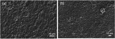 | ||
Fig. 5 SEM images of lithium metal coated with a PVDF-HFP![[thin space (1/6-em)]](https://www.rsc.org/images/entities/char_2009.gif) : :![[thin space (1/6-em)]](https://www.rsc.org/images/entities/char_2009.gif) DMF coating (a) before cycling and (b) after 10 cycles in a SPAN pouch cell. DMF coating (a) before cycling and (b) after 10 cycles in a SPAN pouch cell. | ||
To further investigate the PVDF-HFP![[thin space (1/6-em)]](https://www.rsc.org/images/entities/char_2009.gif) :
:![[thin space (1/6-em)]](https://www.rsc.org/images/entities/char_2009.gif) DMF treatment, we conducted postmortem XPS. Fig. 6a show the XPS spectrum corresponding to pristine PVD-HFP. In this spectrum, there is no LiF signature and only a signal from the C–F bond in the polymer is present. By contrast, a LiF signature is clearly present in the spectra for the PVDF-HFP
DMF treatment, we conducted postmortem XPS. Fig. 6a show the XPS spectrum corresponding to pristine PVD-HFP. In this spectrum, there is no LiF signature and only a signal from the C–F bond in the polymer is present. By contrast, a LiF signature is clearly present in the spectra for the PVDF-HFP![[thin space (1/6-em)]](https://www.rsc.org/images/entities/char_2009.gif) :
:![[thin space (1/6-em)]](https://www.rsc.org/images/entities/char_2009.gif) DMF coating on lithium metal via the solid–liquid–solid conversion method, taken before cycling (Fig. 6b). This LiF peak indicates that there is a reaction with PVDF-HFP, DMF, and lithium to form LiF. Previous works achieved the complete defluorination of the polymer using a ratio of 1 to 10 of PVDF-HFP DMF.22 However, we use a 1
DMF coating on lithium metal via the solid–liquid–solid conversion method, taken before cycling (Fig. 6b). This LiF peak indicates that there is a reaction with PVDF-HFP, DMF, and lithium to form LiF. Previous works achieved the complete defluorination of the polymer using a ratio of 1 to 10 of PVDF-HFP DMF.22 However, we use a 1![[thin space (1/6-em)]](https://www.rsc.org/images/entities/char_2009.gif) :
:![[thin space (1/6-em)]](https://www.rsc.org/images/entities/char_2009.gif) 1 ratio of PVDF-HFP
1 ratio of PVDF-HFP![[thin space (1/6-em)]](https://www.rsc.org/images/entities/char_2009.gif) :
:![[thin space (1/6-em)]](https://www.rsc.org/images/entities/char_2009.gif) DMF to facilitate a partial de-fluorination of the polymer to yield a mixture of inorganic (LiF) and organic (partly de-fluorinated polymer) components. We believe this combination is important for both stable Li-ion flux and for accommodating the lithium volume change. Fig. 6c show the postmortem XPS spectra for the cycled lithium anode coated with PVDF-HFP
DMF to facilitate a partial de-fluorination of the polymer to yield a mixture of inorganic (LiF) and organic (partly de-fluorinated polymer) components. We believe this combination is important for both stable Li-ion flux and for accommodating the lithium volume change. Fig. 6c show the postmortem XPS spectra for the cycled lithium anode coated with PVDF-HFP![[thin space (1/6-em)]](https://www.rsc.org/images/entities/char_2009.gif) :
:![[thin space (1/6-em)]](https://www.rsc.org/images/entities/char_2009.gif) DMF. Here, we observed an increase in the relative surface concentration of LiF. This is evidenced by the increase in relative peak height with respect to the C–F polymer peak. The increase in LiF is likely due to electrolyte salt decomposition and continued defluorination of the polymer.50
DMF. Here, we observed an increase in the relative surface concentration of LiF. This is evidenced by the increase in relative peak height with respect to the C–F polymer peak. The increase in LiF is likely due to electrolyte salt decomposition and continued defluorination of the polymer.50
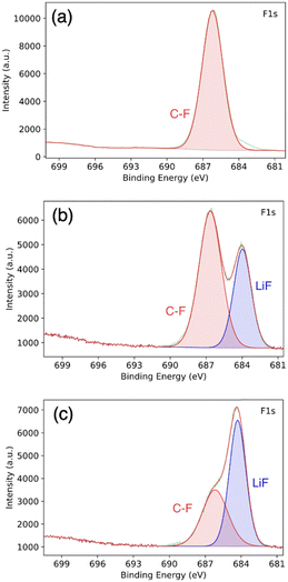 | ||
Fig. 6 XPS of (a) pure PVDF-HFP, (b) PVDF-HFP![[thin space (1/6-em)]](https://www.rsc.org/images/entities/char_2009.gif) : :![[thin space (1/6-em)]](https://www.rsc.org/images/entities/char_2009.gif) DMF coated lithium before cycling, and (c) lithium metal coated with PVDF-HFP DMF coated lithium before cycling, and (c) lithium metal coated with PVDF-HFP![[thin space (1/6-em)]](https://www.rsc.org/images/entities/char_2009.gif) : :![[thin space (1/6-em)]](https://www.rsc.org/images/entities/char_2009.gif) DMF after cycling. DMF after cycling. | ||
To evaluate the impact of the PVDF-HFP![[thin space (1/6-em)]](https://www.rsc.org/images/entities/char_2009.gif) :
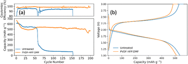
:![[thin space (1/6-em)]](https://www.rsc.org/images/entities/char_2009.gif) DMF lithium protection layer on the electrochemical performance, the treated anode was paired with a closed system SPAN cathode. Fig. 7a compares SPAN pouch cells with an untreated and treated anode. Fig. 7b is the corresponding voltage profile for the 50th cycle that shows the typical single plateau behavior for SPAN in carbonate electrolyte. The pouch cells were cycled at a C/2SPAN rate. The pouch cell with no lithium treatment showed an initial capacity of 610 mA h g−1SPAN (1137 mA h gsulfur−1). However, it failed at 55 cycles. This illustrates that carbonate electrolytes alone cannot provide enough lithium stability. By contrast, the pouch cell employing the lithium anode coated with PVDF-HFP
DMF lithium protection layer on the electrochemical performance, the treated anode was paired with a closed system SPAN cathode. Fig. 7a compares SPAN pouch cells with an untreated and treated anode. Fig. 7b is the corresponding voltage profile for the 50th cycle that shows the typical single plateau behavior for SPAN in carbonate electrolyte. The pouch cells were cycled at a C/2SPAN rate. The pouch cell with no lithium treatment showed an initial capacity of 610 mA h g−1SPAN (1137 mA h gsulfur−1). However, it failed at 55 cycles. This illustrates that carbonate electrolytes alone cannot provide enough lithium stability. By contrast, the pouch cell employing the lithium anode coated with PVDF-HFP![[thin space (1/6-em)]](https://www.rsc.org/images/entities/char_2009.gif) :
:![[thin space (1/6-em)]](https://www.rsc.org/images/entities/char_2009.gif) DMF showed an initial capacity of 625 mA h g−1SPAN (1166 mA h gsulfur−1). It stabilized around 530 mA h g−1SPAN (988 mA h gsulfur−1) and lasted nearly five times longer than the untreated pouch cell. At 150 cycles it had a capacity of 518 mA h g−1SPAN (966 mA h gsulfur−1), representing a capacity retention of 90%. At 200 cycles, it had a capacity of 471 mA h g−1SPAN (879 mA h gsulfur−1), representing a capacity retention of 82%. This demonstrates that the PVDF-HFP
DMF showed an initial capacity of 625 mA h g−1SPAN (1166 mA h gsulfur−1). It stabilized around 530 mA h g−1SPAN (988 mA h gsulfur−1) and lasted nearly five times longer than the untreated pouch cell. At 150 cycles it had a capacity of 518 mA h g−1SPAN (966 mA h gsulfur−1), representing a capacity retention of 90%. At 200 cycles, it had a capacity of 471 mA h g−1SPAN (879 mA h gsulfur−1), representing a capacity retention of 82%. This demonstrates that the PVDF-HFP![[thin space (1/6-em)]](https://www.rsc.org/images/entities/char_2009.gif) :
:![[thin space (1/6-em)]](https://www.rsc.org/images/entities/char_2009.gif) DMF coating is effective at providing lithium stability and prolonging battery life. Finally, we note that the untreated pouch cell does not show the same stability as in coin cells because the larger pouch cell format exacerbates the issues seen at both electrodes.16 By contrast, the pouch cell with the treated lithium anode lasts much longer, highlighting the effectiveness of the anode treatment, despite the challenges that arise when operating at the larger pouch cell format.
DMF coating is effective at providing lithium stability and prolonging battery life. Finally, we note that the untreated pouch cell does not show the same stability as in coin cells because the larger pouch cell format exacerbates the issues seen at both electrodes.16 By contrast, the pouch cell with the treated lithium anode lasts much longer, highlighting the effectiveness of the anode treatment, despite the challenges that arise when operating at the larger pouch cell format.
Fig. 8 shows EIS curves for a coin cell with an SPAN cathode and an anode treated with PVDF-HFP![[thin space (1/6-em)]](https://www.rsc.org/images/entities/char_2009.gif) :
:![[thin space (1/6-em)]](https://www.rsc.org/images/entities/char_2009.gif) DMF. The SEI resistance, represented by the first semicircle, has a resistance of around 25 Ω. This SEI transfer resistance remains constant after 50 cycles, but the charge transfer resistance, represented by the second semicircle, decreases.51 This is likely due to the conversion of less conductive PVDF-HFP polymer to LiF, improving charge transfer by creating a more uniform electric field.52 This would aid in lithium deposition likely contributes to the lithium stability seen in the pouch cell cycling.
DMF. The SEI resistance, represented by the first semicircle, has a resistance of around 25 Ω. This SEI transfer resistance remains constant after 50 cycles, but the charge transfer resistance, represented by the second semicircle, decreases.51 This is likely due to the conversion of less conductive PVDF-HFP polymer to LiF, improving charge transfer by creating a more uniform electric field.52 This would aid in lithium deposition likely contributes to the lithium stability seen in the pouch cell cycling.
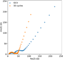 | ||
Fig. 8 EIS of coin cells with a closed system SPAN cathode and PVDF-HFP![[thin space (1/6-em)]](https://www.rsc.org/images/entities/char_2009.gif) : :![[thin space (1/6-em)]](https://www.rsc.org/images/entities/char_2009.gif) DMF coated lithium anodes at OCV and after 50 cycles. DMF coated lithium anodes at OCV and after 50 cycles. | ||
4. Conclusions
In this work, we developed a SPAN synthesis method that increased the sulfur percentage in SPAN material from 45.30%, in the traditional open system, to 53.62% in our closed system. This represents an increase of 18% in active material that can provide capacity, resulting in a SPAN material with higher energy density. We paired this closed system SPAN cathode material with a PVDF-HFP![[thin space (1/6-em)]](https://www.rsc.org/images/entities/char_2009.gif) :
:![[thin space (1/6-em)]](https://www.rsc.org/images/entities/char_2009.gif) DMF lithium metal anode treatment that created a uniform layer of LiF and partially defluorinated polymer. This protective layer created a robust, stable artificial SEI on the lithium metal surface that promoted uniform lithium-ion flux to the anode and inhibited the formation of the dead lithium layer. The Li-SPAN pouch cell with the treated anode achieved a capacity of 471 mA h g−1SPAN (879 mA h gsulfur−1) at 200 cycles while maintaining 82% capacity retention. It lasted nearly five times longer than a pouch cell without a treated anode. This treatment enabled the use of a higher sulfur percentage SPAN material to create a Li-SPAN pouch cell with higher energy density than traditional SPAN material while utilizing a commercial carbonate electrolyte.
DMF lithium metal anode treatment that created a uniform layer of LiF and partially defluorinated polymer. This protective layer created a robust, stable artificial SEI on the lithium metal surface that promoted uniform lithium-ion flux to the anode and inhibited the formation of the dead lithium layer. The Li-SPAN pouch cell with the treated anode achieved a capacity of 471 mA h g−1SPAN (879 mA h gsulfur−1) at 200 cycles while maintaining 82% capacity retention. It lasted nearly five times longer than a pouch cell without a treated anode. This treatment enabled the use of a higher sulfur percentage SPAN material to create a Li-SPAN pouch cell with higher energy density than traditional SPAN material while utilizing a commercial carbonate electrolyte.
Conflicts of interest
There are no conflicts to declare.Acknowledgements
The authors would like to acknowledge funding from the National Science Foundation (award numbers: NSF-2211049 and NSF-1919177). We would also like to acknowledge the Materials and Characterization Core (MCC) staff and instrument time at Drexel University. Finally, thanks to Dr Michelle Gannon and Professor David Velinksy from the Academy of Natural Sciences at Drexel University for their help with elemental analysis of our samples.References
- C. Li, H. Zhang, L. Otaegui, G. Singh, M. Armand and L. M. Rodriguez-Martinez, J. Power Sources, 2016, 326, 1–5 CrossRef.
- J. Li, Z. Du, R. E. Ruther, S. J. An, L. A. David, K. Hays, M. Wood, N. D. Phillip, Y. Sheng, C. Mao, S. Kalnaus, C. Daniel and D. L. Wood, JOM, 2017, 69, 1484–1496 CrossRef.
- M. Hagen, D. Hanselmann, K. Ahlbrecht, R. Maça, D. Gerber and J. Tübke, Adv. Energy Mater., 2015, 5 Search PubMed.
- L. Su, M. Ferrandon, J. L. Barton, N. U. de la Rosa, J. T. Vaughey and F. R. Brushett, Electrochim. Acta, 2017, 246, 251–258 CrossRef.
- D. H. Doughty, E. P. Roth, C. C. Crafts, G. Nagasubramanian, G. Henriksen and K. Amine, J. Power Sources, 2005, 146, 116–120 CrossRef.
- S. S. Zhang, J. Power Sources, 2006, 162, 1379–1394 CrossRef.
- J. Yan, X. Liu, X. Wang and B. Li, J. Mater. Chem. A, 2015, 3, 10127–10133 RSC.
- X. Wang, Y. Qian, L. Wang, H. Yang, H. Li, Y. Zhao and T. Liu, Adv. Funct. Mater., 2019, 29 Search PubMed.
- S. Wei, L. Ma, K. E. Hendrickson, Z. Tu and L. A. Archer, J. Am. Chem. Soc., 2015, 137, 12143–12152 CrossRef PubMed.
- H. Li, W. Xue, W. Xu, L. Wang and T. Liu, Compos. Commun., 2021, 24 Search PubMed.
- X. Zhao, C. Wang, Z. Li, X. Hu, A. Abdul Razzaq and Z. Deng, J. Mater. Chem. A, 2021, 9, 19282–19297 RSC.
- X. B. Cheng, R. Zhang, C. Z. Zhao and Q. Zhang, Chem. Rev., 2017, 117, 10403–10473 CrossRef.
- D. Lin, Y. Liu and Y. Cui, Nat. Nanotechnol., 2017, 12, 194–206 CrossRef PubMed.
- J. Steiger, D. Kramer and R. Mönig, J. Power Sources, 2014, 261, 112–119 CrossRef.
- A. Hagopian, M.-L. Doublet and J.-S. Filhol, Energy Environ. Sci., 2020, 13, 5186–5197 RSC.
- X.-B. Cheng, C. Yan, J.-Q. Huang, P. Li, L. Zhu, L. Zhao, Y. Zhang, W. Zhu, S.-T. Yang and Q. Zhang, Energy Storage Mater., 2017, 6, 18–25 CrossRef.
- X. Ren, L. Zou, S. Jiao, D. Mei, M. H. Engelhard, Q. Li, H. Lee, C. Niu, B. D. Adams, C. Wang, J. Liu, J.-G. Zhang and W. Xu, ACS Energy Lett., 2019, 4, 896–902 CrossRef.
- T. M. Hagos, T. T. Hagos, H. K. Bezabh, G. B. Berhe, L. H. Abrha, S.-F. Chiu, C.-J. Huang, W.-N. Su, H. Dai and B. J. Hwang, ACS Appl. Energy Mater., 2020, 3, 10722–10733 CrossRef.
- H. Zhang, G. G. Eshetu, X. Judez, C. Li, L. M. Rodriguez-Martinez and M. Armand, Angew. Chem., Int. Ed., 2018, 57, 15002–15027 Search PubMed.
- H. Wang, J. Wu, L. Yuan, Z. Li and Y. Huang, ACS Appl. Mater. Interfaces, 2020, 12, 28337–28344 CrossRef PubMed.
- A. J. Louli, M. Genovese, R. Weber, S. G. Hames, E. R. Logan and J. R. Dahn, J. Electrochem. Soc., 2019, 166, A1291–A1299 CrossRef.
- S. Guo, N. Piao, L. Wang, H. Xu, G. Tian, J. Li and X. He, ACS Appl. Energy Mater., 2020, 3, 7191–7199 CrossRef.
- N. Xu, J. Shi, G. Liu, X. Yang, J. Zheng, Z. Zhang and Y. Yang, J. Power Sources Adv., 2021, 7 Search PubMed.
- L. Fan, H. L. Zhuang, L. Gao, Y. Lu and L. A. Archer, J. Mater. Chem. A, 2017, 5, 3483–3492 RSC.
- J. Zhao, L. Liao, F. Shi, T. Lei, G. Chen, A. Pei, J. Sun, K. Yan, G. Zhou, J. Xie, C. Liu, Y. Li, Z. Liang, Z. Bao and Y. Cui, J. Am. Chem. Soc., 2017, 139, 11550–11558 CrossRef CAS PubMed.
- J. Lang, Y. Long, J. Qu, X. Luo, H. Wei, K. Huang, H. Zhang, L. Qi, Q. Zhang, Z. Li and H. Wu, Energy Storage Mater., 2019, 16, 85–90 CrossRef.
- S. Sun, S. Myung, G. Kim, D. Lee, H. Son, M. Jang, E. Park, B. Son, Y.-G. Jung, U. Paik and T. Song, J. Mater. Chem. A, 2020, 8, 17229–17237 RSC.
- Z. X. Chen, M. Zhao, L. P. Hou, X. Q. Zhang, B. Q. Li and J. Q. Huang, Adv. Mater., 2022, 34, e2201555 CrossRef.
- S. Dörfler, H. Althues, P. Härtel, T. Abendroth, B. Schumm and S. Kaskel, Joule, 2020, 4, 539–554 CrossRef.
- T. Ma, Y. Ni, D. Li, Z. Zha, S. Jin, W. Zhang, L. Jia, Q. Sun, W. Xie, Z. Tao and J. Chen, Angew. Chem., Int. Ed., 2023, 62, e202310761 CrossRef CAS.
- Z. Shen, W. Zhang, S. Mao, S. Li, X. Wang and Y. Lu, ACS Energy Lett., 2021, 6, 2673–2681 CrossRef CAS.
- X. Duan, L. Wang, G. Li, X. Liu, M. Wan, J. Du, R. Zhan, W. Wang, Y. Li, S. Tu, Y. Shen, Z. W. Seh, L. Wang and Y. Sun, Adv. Funct. Mater., 2022, 33 CAS.
- G. Cai, J. Holoubek, M. Li, H. Gao, Y. Yin, S. Yu, H. Liu, T. A. Pascal, P. Liu and Z. Chen, Proc. Natl. Acad. Sci. U. S. A., 2022, 119, e2200392119 CrossRef CAS PubMed.
- L. Yi, C. Zou, X. Chen, J. Liu, S. Cao, X. Tao, Z. Zang, L. Liu, B. Chang, Y. Shen and X. Wang, ACS Appl. Energy Mater., 2022, 5, 7317–7327 CrossRef CAS.
- J. Jie, Y. Liu, L. Cong, B. Zhang, W. Lu, X. Zhang, J. Liu, H. Xie and L. Sun, J. Energy Chem., 2020, 49, 80–88 CrossRef.
- W. Wang, Z. Cao, G. A. Elia, Y. Wu, W. Wahyudi, E. Abou-Hamad, A.-H. Emwas, L. Cavallo, L.-J. Li and J. Ming, ACS Energy Lett., 2018, 3, 2899–2907 CrossRef CAS.
- X. Yu, J. Xie, Y. Li, H. Huang, C. Lai and K. Wang, J. Power Sources, 2005, 146, 335–339 CrossRef CAS.
- X.-G. Yu, J.-Y. Xie, J. Yang, H.-J. Huang, K. Wang and Z.-S. Wen, J. Electroanal. Chem., 2004, 573, 121–128 CAS.
- T. H. Hwang, D. S. Jung, J. S. Kim, B. G. Kim and J. W. Choi, Nano Lett., 2013, 13, 4532–4538 CrossRef CAS PubMed.
- J. Wang, Y. S. He and J. Yang, Adv. Mater., 2015, 27, 569–575 CrossRef CAS PubMed.
- R. Shokrani Havigh and H. Mahmoudi Chenari, Sci. Rep., 2022, 12, 10704 CrossRef CAS.
- C. X. Zhao, W. J. Chen, M. Zhao, Y. W. Song, J. N. Liu, B. Q. Li, T. Yuan, C. M. Chen, Q. Zhang and J. Q. Huang, EcoMat, 2020, 3 Search PubMed.
- R. Mukkabla and M. R. Buchmeiser, J. Mater. Chem. A, 2020, 8, 5379–5394 RSC.
- C.-J. Huang, J.-H. Cheng, W.-N. Su, P. Partovi-Azar, L.-Y. Kuo, M.-C. Tsai, M.-H. Lin, S. Panahian Jand, T.-S. Chan, N.-L. Wu, P. Kaghazchi, H. Dai, P. M. Bieker and B.-J. Hwang, J. Power Sources, 2021, 492 Search PubMed.
- A. Salimi and A. A. Yousefi, J. Polym. Sci., Part B: Polym. Phys., 2004, 42, 3487–3495 CrossRef CAS.
- T. Boccaccio, A. Bottino, G. Capannelli and P. Piaggio, J. Membr. Sci., 2002, 210, 315–329 CrossRef CAS.
- R. Gregorio, J. Appl. Polym. Sci., 2006, 100, 3272–3279 CrossRef CAS.
- S. Manna, S. K. Batabyal and A. K. Nandi, J. Phys. Chem. B, 2006, 110, 12318–12326 CrossRef CAS.
- X. Wang, X. Hao, Z. Hengjing, X. Xia and J. Tu, Electrochim. Acta, 2020, 329 Search PubMed.
- D. Aurbach, E. Pollak, R. Elazari, G. Salitra, C. S. Kelley and J. Affinito, J. Electrochem. Soc., 2009, 156 Search PubMed.
- S. Waluś, C. Barchasz, R. Bouchet and F. Alloin, Electrochim. Acta, 2020, 359 Search PubMed.
- J. Qian, W. Xu, P. Bhattacharya, M. Engelhard, W. A. Henderson, Y. Zhang and J.-G. Zhang, Nano Energy, 2015, 15, 135–144 CrossRef CAS.
Footnotes |
| † Electronic supplementary information (ESI) available. See DOI: https://doi.org/10.1039/d3ya00423f |
| ‡ Equal contribution. |
| This journal is © The Royal Society of Chemistry 2024 |

