
 Open Access Article
 This Open Access Article is licensed under a Creative Commons Attribution-Non Commercial 3.0 Unported Licence
A multifunctional rooftop unit for direct air capture†‡
Keju
An§
a,
Jamieson
Brechtl
a,
Stephen
Kowalski
 a,
Cheng-Min
Yang
a,
Michelle K.
Kidder
b,
Costas
Tsouris
b,
Christopher
Janke
c,
Meghan
Lamm
b,
Katie
Copenhaver
b,
Josh
Thompson¶
b,
Tugba
Turnaoglu
a,
Brian
Fricke
a,
Kai
Li
*a,
Xin
Sun
d and
Kashif
Nawaz
*a
a,
Cheng-Min
Yang
a,
Michelle K.
Kidder
b,
Costas
Tsouris
b,
Christopher
Janke
c,
Meghan
Lamm
b,
Katie
Copenhaver
b,
Josh
Thompson¶
b,
Tugba
Turnaoglu
a,
Brian
Fricke
a,
Kai
Li
*a,
Xin
Sun
d and
Kashif
Nawaz
*a
aBuildings and Transportation Science Division, Oak Ridge National Laboratory, Oak Ridge, TN 37830, USA. E-mail: lik1@ornl.gov; nawazk@ornl.gov
bManufacturing Science Division, Oak Ridge National Laboratory, Oak Ridge, TN 37830, USA
cChemical Sciences Division, Oak Ridge National Laboratory, Oak Ridge, TN 37830, USA
dEnergy Science & Technology Directorate, Oak Ridge National Laboratory, Oak Ridge, TN 37830, USA
First published on 6th May 2024
Abstract
Direct air capture (DAC), which captures CO2 from ambient air, is a critical technology to reduce greenhouse gases in the atmosphere in order to avoid climate disasters. Due to the relatively low concentration of CO2 (400 ppm), a large amount of air needs to be moved through DAC devices, which requires lots of energy. Currently, DAC technologies are deployed mainly in centralized systems and require extensive infrastructure and initial capital cost. A potential solution is to utilize existing infrastructure for DAC. In this study, we propose a distributed DAC system that utilizes existing commercial rooftop heating and air conditioning (HVAC) units to capture CO2 from the air. There are approximately 15 million such units already installed on commercial buildings in the United States, and they move a large amount of air every day. Adding DAC functionality to these units will significantly reduce the cost of infrastructure and operation. A modular approach was used to introduce DAC into a rooftop unit. Modules filled with triethylenetetramine-functionalized polyacrylonitrile sheets were developed and installed on the condenser coil side of the rooftop unit. The rooftop unit with DAC functions effectively captured CO2 from the air, and the addition of the DAC modules had little effect on the unit's original functionality. A preliminary techno-economic analysis was also conducted, and the results potentially suggest that utilizing existing commercial rooftop units for carbon capture is a feasible approach to reducing greenhouse gases.
Environmental significanceDirect air capture (DAC) is a promising and widely accepted technology that can address climate challenges by directly capturing CO2 from the atmosphere through chemical or physical absorption processes. Currently, DAC technologies are deployed mainly in centralized systems and require extensive infrastructure and initial capital cost. One strategy to reduce the infrastructure cost of DAC systems is to use existing infrastructure. In the DAC process, a large quantity of air is moved through the contactor (sorbent system) to be captured by the sorbents, which need high energy input. The cost and energy input for DAC systems could be reduced by combining the DAC function with other existing infrastructure/equipment. Rooftop units (RTUs) move ambient air across a heat exchanger to transfer heat between the refrigerant and the ambient air. The addition of DAC modules to the RTU would make use of the already existing equipment and multi-functionalize the device. Utilizing existing commercial rooftop units for carbon capture is a feasible approach to reducing greenhouse gases. |
1. Introduction
Since the industrial revolution, gigatons of CO2 have been emitted into the atmosphere.1 This greenhouse gas is released primarily through the burning of fossil fuels and other industrial activities. If the release of CO2 is not carefully abated, the global mean temperature is projected to increase 2–4 °C over the last second half of this century.2 Several previous reports3 have suggested that such changes to the climate can cause sea level rise induced by glacier recession,4,5 increased sedimentation in river basins,6 changes in vegetation patterns and agricultural yield,7–9 reduced food security,10 and other deleterious outcomes. Thus, the reduction and mitigation of CO2 in the atmosphere is one major challenge for humanity as a whole.One method to reduce the amount of atmospheric CO2 is via direct air capture (DAC) technologies, which use sorption processes to extract CO2 directly from the atmosphere. Because of the relatively low concentration of CO2 in the air, chemical absorption dominates the DAC development, even though some physical adsorbents such as metal–organic frameworks (MOFs) can be used. Both solid and liquid sorbents have been developed and show promising results in various DAC systems. Examples of solid and liquid sorbents include amine-functionalized silica and aqueous NaOH, respectively.11 However, the adsorption mechanisms of these two types of sorbents differ significantly.12 Carbon dioxide is adsorbed on the surfaces of solid sorbents and can subsequently be released when the material is subjected to relatively low temperatures of 80 to 120 °C. As for liquid sorbents, CO2 typically binds with a liquid flowing through a packed bed-air contactor; the CO2 can then be released using regeneration methods that involve heating the solution.13,14 One disadvantage of liquid sorbents is that regeneration usually requires heating temperatures significantly higher (approximately 900 °C14) than those required by solid sorbents. Because they consume less energy than liquid processes during regeneration, solid DAC processes have been extensively adopted by several companies, such as Climeworks and Global Thermostat.
Table 1 provides selected CO2 capture data of reported adsorbent materials under different experimental conditions.11 The amines had the highest CO2 uptakes (1.09–6.85 mmol g−1), whereas the zeolites had the lowest uptakes (0.15–0.87 mmol g−1). The Mg-MOF-74 sorbent had the lowest CO2 uptake of the listed materials. Lastly—unlike the MOFs, zeolites, and alkali carbonates—the amines exhibited higher CO2 uptake values at levels typical of ambient air environments.
| Type | Sorbents | CO2 uptake (mmol g−1) | Absorption conditions | Ref. |
|---|---|---|---|---|
| Amine-functionalized | Pentaethylenehexamine | 6.85 | 25 °C, 400 ppm | 15 |
| Monoethanolamine | 1.92 | 25 °C, 440 ppm | 16 | |
| 2-Amino-2-methyl-1-propanol | 1.09 | 25 °C, 440 ppm | 16 | |
| Metal–organic framework (MOF) | Mg-MOF-74 | 0.05 | 25 °C, 500 ppm | 17 |
| ZU-16-Co | 1.05 | 25 °C, 400 ppm | 18 | |
| mmen-Mg2 (dobpdc) | 2.05 | 25 °C, 390 ppm | 19 | |
| Zeolite | Low-silica type X (LSX) | 0.87 | 25 °C, 395 ppm | 20 |
| Zeolite 13X | 0.40 | 25 °C, 500 ppm | 17 | |
| Tetraethylenepentamine-ZSM-5 | 0.15 | 25 °C, 5000 ppm | 21 | |
| Alkali carbonate | K2CO3/γ-Al2O3 | 1.15 | Ambient air | 22 |
| K2CO3/ZrO2 | 1.04 | 25 °C, 450 ppm | 23 | |
| K2CO3/Y2O3 | 0.64 | Ambient air | 24 |
Most current state-of-the-art DAC technology is deployed in centralized systems, where large carbon capture apparatus can directly inject captured carbon dioxide into geologic formations. Though they have the advantage of being co-located with the eventual storage site, they require extensive infrastructure to be built, which could lead to various associated challenges.25 For example, the overall energy demand may limit the system's scalability if it is too great relative to the regional or global power supply.26 Additionally, because stand-alone DAC systems are in the early stages of development, an exhaustive techno-economic assessment of these technologies has yet to be performed.27 The sorbents used in DAC systems also present a challenge because they must demonstrate that they can efficiently react with air mixtures containing low concentrations of CO2.25 An issue for the current DAC systems is the relatively high cost of CO2 storage, which can be in excess of $600/ton with current carbon capture technologies.28 New technologies are needed to reduce this cost to below $100/ton,29 which would help fulfill a goal of the Carbon Negative Shot (one of the US Department of Energy's (DOE's) Energy Earthshot Initiatives) and make DAC a potentially viable technology.30–32
The requirement of equipment and electricity of these synthetic DAC technologies puts them at a major disadvantage as compared to natural DAC systems such as trees. In the former, electricity is needed not only to capture CO2 but also to compress it for transfer in the pipeline. One must then ask the question as to whether renewable electricity used for synthetic DAC would be more effective in reducing atmospheric CO2 than using the same quantity of renewable electricity to replace a fossil source of CO2 such as that from coal or natural gas power plants. A study by Jacobson33 suggested that this would not be the case. For example, they found that using wind to run a DAC system reduced less CO2 than using it to replace a coal electricity generating plant. Furthermore, replacing a coal power plant with renewable energy sources reduces air pollution, coal mining, and coal infrastructure as well, whereas using a synthetic DAC system does not. As a result, the social cost benefit of using wind to replace coal was 5–10 times that of using it to run DAC in that study. In summary, the use of wind and solar in place of coal for electricity production is more effective in reducing atmospheric CO2 than using synthetic DAC technologies that are powered by renewable energy sources.
One strategy to reduce the infrastructure cost of DAC systems is to use existing infrastructure. In the DAC process, a large quantity of air is moved through the contactor (sorbent system) to be captured by the sorbents, which need high energy input. The cost and energy input for DAC systems could be reduced by combining the DAC function with other existing infrastructure/equipment. Rooftop units (RTUs) move ambient air across a heat exchanger to transfer heat between the refrigerant and the ambient air. The addition of DAC modules to the RTU would make use of the already existing pressure drop in the RTU and multi-functionalize the device. Fig. 1 illustrates a possible RTU configuration with DAC integrated, wherein the DAC modules are upstream of the outdoor coil. Currently, RTUs are the dominant method of heating and cooling for light commercial applications. The major advantages of RTUs include no working parts in the living space, lower construction costs, and efficient design modification.34 An estimated 15 million RTUs are currently on commercial buildings in the United States.35 Because RTUs already move ambient air as part of their primary function, the additional energy necessary to overcome the added pressure drop required by DAC may be less than the energy required for current dedicated DAC technologies such as the Climeworks Capricorn system,36 though methods to transport the captured CO2 to storage sites would require further energy usage for compression and pumping. Recently, Climeworks employed DAC technology on a system with overall dimensions similar to an RTU that was also mounted on a rooftop37 and was reportedly able to adsorb the carbon equivalent of 36![[thin space (1/6-em)]](https://www.rsc.org/images/entities/char_2009.gif) 000 trees.38 The CO2 collected can be stored as carbonate minerals by exposing it to alkaline-rich minerals or recycled into chemicals and fuels including, methanol, dimethyl ether, and hydrocarbons.26,39,40
000 trees.38 The CO2 collected can be stored as carbonate minerals by exposing it to alkaline-rich minerals or recycled into chemicals and fuels including, methanol, dimethyl ether, and hydrocarbons.26,39,40
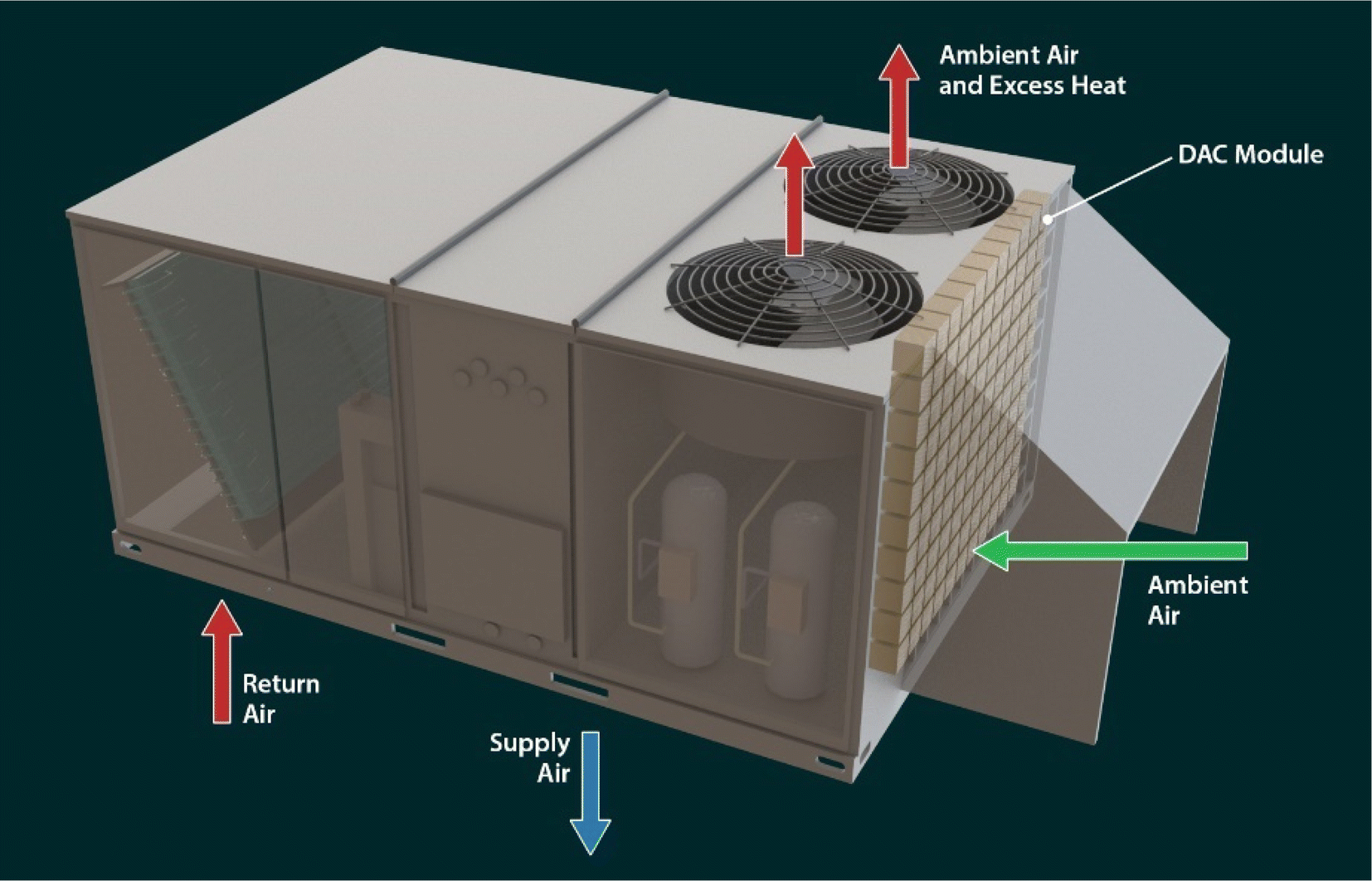 | ||
| Fig. 1 Schematic of a typical unitary roof top unit with the DAC module. | ||
Currently, very few studies on distributed DAC technology exist. Recently, Sadiq et al. reported a mobile DAC system that employed a MOF-based nanocomposite41 and was incorporated within a mobile unit for distributed deployment. Their results showed an operational cost of $35–$350 ton-CO2−1 depending on the source of regeneration energy. Li et al.42 reviewed mobile DAC as a route to scaling up DAC through distributed deployment on vehicles, ships, low- and high-altitude aircraft, and others. So far, however, there have been no studies that comprehensively examine both the costs of and the effects of an outdoor environment on a distributed RTU DAC system. Therefore, the purpose of this study is to provide a novel investigation on how weather, airflow, and fan power affect the CO2 capture performance and cost of a distributed DAC RTU system to assess the feasibility of this technology. It is understood that the use of DAC with an RTU will inevitably increase the power usage of the RTU. With much of today's electricity supplied by sources that increase atmospheric CO2, the increased power usage of the RTU could result in a net increase in atmospheric CO2 rather than a decrease as was observed by Jacobson.33 However, in the future when fossil fuel combustion is no longer used to produce power, but further atmospheric CO2 removal is still necessary, many methods of DAC may be deployed to reduce atmospheric CO2 levels.30
2. Methodology
2.1 Preparation of the RTU for CO2 capture
A unitary rooftop heat pump or air conditioner, either of which may be called an RTU, contains a mechanical refrigeration system and an indoor and outdoor fan along with their associated controls. The RTU is usually installed on the roof or beside a building to provide heating or cooling for occupant comfort. Fig. 1 shows the schematic of a typical RTU installed on the rooftop. The conditioned air moves through the roof and enters the bottom of the unit as return air. After being heated or cooled and dehumidified, it returns to the conditioned space as supply air, again through the bottom of the unit and the roof. The supply air is distributed through ductwork to different areas of the conditioned space. The mechanical refrigeration system requires that heat transferred from the conditioned space to the refrigerant during cooling mode be rejected to the ambient. This heat transfer takes place in the outdoor coil, through which ambient air is moved by the outdoor fan (or fans). Similarly, in heating mode, the heat that is added to the conditioned space by the refrigeration system is extracted from the ambient through the outdoor coil, through which ambient air is moved by the outdoor fan(s). Generally speaking, commercial RTUs move air using two major subsystems, namely the indoor and outdoor fans, during normal operation.A significant amount of air moves through RTUs. Since ambient air with a low concentration of CO2 (approximately 415 ppm) is already moving through the outdoor coil and fan subsystem; this work focuses on extracting CO2 from the ambient air using this readily available source. A significant amount of air moves through RTUs. For instance, the ASHRAE HVAC Systems and Equipment handbook notes that airflow can be 80–160 L s−1 (170–340 cfm) for a heat transfer of 4.2 kW (14330 Btu h−1) and a 17 K temperature difference.43 However, airflow values are higher in the available literature for commercial RTUs. For example, Trane Technologies and Johnson Controls provide data on commercial packaged RTUs. Data for the Trane Precedent44 and Voyager 2 (ref. 45) product lines show an average airflow of 834 cfm/ton. Data for the Johnson Controls Series 5,46 ZX/ZY/ZQ/ZL,47 and Series 2048 product lines show an average condenser airflow of 941 cfm/ton. Both airflow rates are significantly higher than those listed in the ASHRAE handbook.43
2.2 Adsorbent synthesis
In this study, triethylenetetramine-functionalized polyacrylonitrile (PAN-TETA) was used as the adsorbent to capture CO2 from the air. PAN-TETA was prepared by reacting polyacrylonitrile (PAN) with triethylenetetramine (TETA) (Scheme 1). The reaction was conducted in 19 L of solution containing PAN and TETA using water as the reaction medium. The amine groups on PAN-TETA can chemically bond with CO2 and achieve a CO2 absorption capacity of 0.33 mmol g−1 in 400 ppm CO2 (in N2). PAN-TETA also adsorbs 55–60% of its weight in moisture at 25–40 °C.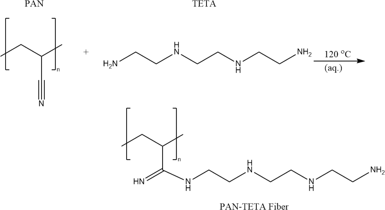 | ||
| Scheme 1 Synthesis of the PAN-TETA. | ||
2.3 Execution of rooftop experiments
For this investigation, modules were designed to orient PAN-TETA optimally for using the airflow through the outdoor coil of a typical RTU. The material was fabricated as sheets with thicknesses of approximately 3 mm. After the sheets were dried, they were cut into rectangles with approximate dimensions of 50 mm (2 in., width) × 100 mm (4 in., length). Groups of these rectangles were stacked into extruded 6063 Al tubes with square cross sections. The extruded Al tube sections, which had dimensions of 110 mm (4.5 in.) × 110 mm, were cut to a depth of approximately 100 mm (4 in.). A UV-resistant polymer mesh with an opening size of 1.59 mm (0.0625 in.) was glued onto the aluminum square containers. Twenty-five rectangles of PAN-TETA were installed into each extruded Al tube section such that the 3 mm × 100 mm (0.25 in. × 4 in.) edge of each rectangle was facing the incoming airflow. This was intended to allow the longest residence time of airflow against PAN-TETA to optimize the absorption process. A photograph of one filled tube module and its corresponding schematic are shown in Fig. 2a and b. Ninety of these modules were assembled, and each module was numbered so its performance could be monitored throughout the experiments. The RTU that was used for testing is shown in Fig. 2c. This unit has been used on a prototype commercial building and has been fully instrumented. The prototype commercial building is located at the Oak Ridge National Laboratory and is referred to as the Flexible Research Platform 2 (FRP 2). This building was documented by Im et al.49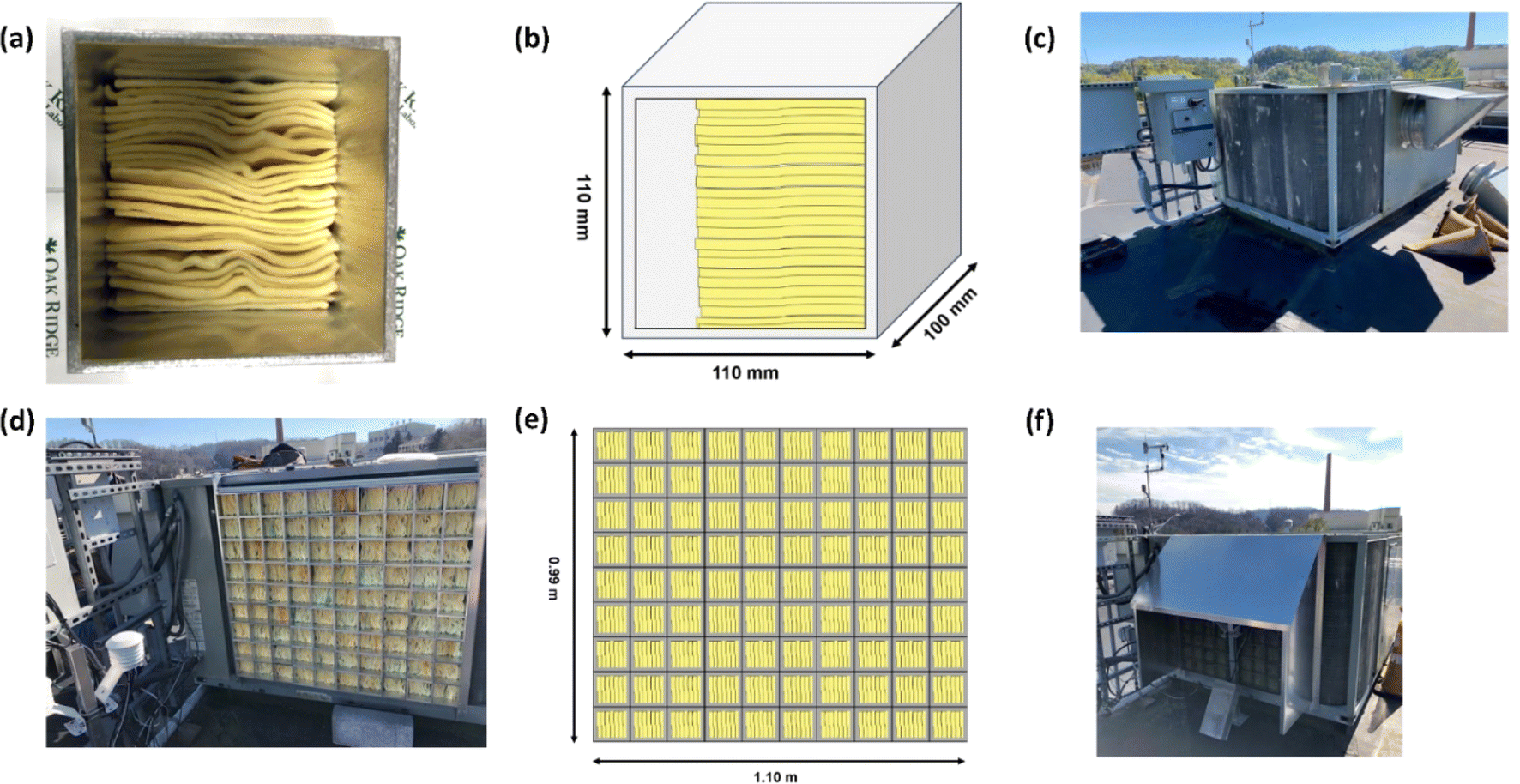 | ||
| Fig. 2 (a) Photograph of a PAN-TETA module, (b) corresponding schematic of the PAN-TETA module, (c) RTU already in service, (d) photograph of the modules installed on the north face of the RTU outdoor coil, (e) corresponding schematic of the installed module system, and (f) rain and sun shield and upstream instrument assembly installed on the north face of the RTU outdoor coil. | ||
Prior to any experiments with PAN-TETA, the face velocity on the outdoor coils was characterized using a hot-wire anemometer (Alnor® Velometer® Thermal Anemometer AVM440) to investigate the effect of face velocity on the absorption rate of PAN-TETA. The face velocity averaged approximately 1 m s−1. Further information about the air face velocities and the measured data are given in the appendix.‡
The modules were installed on a rack system with the end covered by the mesh material directly against the fins of the outdoor coil on the two exposed faces, north and west. Fig. 2d and e show the modules assembled on the north face and its corresponding schematic, respectively. A map of the modules was maintained such that the same module was placed in the same location for each test. Another layer of the same mesh material was installed on the outside of the modules to limit the amount of foreign material that PAN-TETA would be exposed to. Furthermore, a sun and rain shield was installed over the DAC modules, as shown in Fig. 2f. Instruments to measure CO2 concentration (Vaisala GMP252), humidity (Vaissala HMP7), and temperature (Vaisala TMP1) were installed both upstream and downstream of the filter modules, and a differential pressure transducer (Omega PX277-05D5V) was installed to measure the pressure drop across the modules and outdoor coil. The upstream instruments were installed in a weatherproof housing. The downstream instruments were installed in a similar housing inside the cabinet between the outdoor coil and the outdoor coil fans. The instruments were added to the existing FRP 2 data acquisition system that was already used to collect data from the RTU. The intention of installing the upstream and downstream CO2 concentration measurement instruments was to determine if the change in CO2 concentration through the modules would be detectable. The CO2 was not detectable using these instruments (Fig. S1‡); however, later analysis with thermogravimetric analysis-mass spectrometry (TGA-MS) showed the amount of CO2 collected (Fig. S2‡). A further discussion of the upstream and downstream CO2 measurements is provided in the appendix.‡
2.4 Sampling and data acquisition
The process used to conduct the experiments with the modules was as follows. The modules were first weighed using an electronic scale (Sartorius MCA20201S). They were then fully dried in an oven at 55 °C until a constant final weight of the material was achieved. The modules were then weighed again before being installed in the RTU. The RTU was typically operated based on the cooling needs of the building only during daytime hours but was occasionally operated based on the 24 h cooling needs of the building. The experiments were conducted from February to October in 2022 to study the adsorption capacity under varying ambient temperature and humidity conditions. The absorbent modules were installed in the RTU and operated for 7 days at a time each month because this was hypothesized to be a suitable amount of time for PAN-TETA to absorb the maximum amount of CO2. The measured ambient air conditions were collected over the operating time of the RTU. At the end of the 7 days, the modules were again weighed to determine the increase in mass from the week's exposure to ambient air. After weighing, small samples were extracted from specific modules to be further analyzed using TGA-MS to identify the amount of CO2 adsorbed. TGA measures weight change (loss or gain) and the rate of weight change of a material as a function of temperature or time under a controlled atmosphere. It has been widely used to evaluate the CO2 absorption and desorption behavior of a sorbent.50,51 The TGA and evolved gas analyses were performed using a TGA 5500 (TA Instruments) coupled with a quadrupole mass spectrometer with a Faraday detector (Cirrus 3, MKS Instruments). Samples between 3 and 7 mg were loaded into Pt pans and allowed to equilibrate at 30 °C. The samples were then heated to 250 °C at 10 °C min−1 under an Ar flow while mass spectrometry (MS) spectra were collected every 3.03 s in an m/z range of 1 to 50. The TGA and MS data were analyzed using Trios software (TA Instruments). Specifically, samples were extracted for TGA from modules installed in areas with higher face velocities as shown in Table 2 to check if the amount of CO2 absorbed was higher because of the higher face velocity, as would be expected.| February 2022 | June 2022 | |||||
|---|---|---|---|---|---|---|
| Mean | Max | Min | Mean | Max | Min | |
| CO2 upstream with RTU module (ppm) | 417.27 | 443.42 | 398.11 | 416.29 | 498.12 | 363.02 |
| CO2 downstream with RTU module (ppm) | 425.15 | 451.10 | 406.91 | 415.46 | 495.85 | 359.13 |
| CO2 upstream without RTU module (ppm) | 416.76 | 495.23 | 397.62 | 400.39 | 455.95 | 367.85 |
| CO2 downstream without RTU module (ppm) | 420.07 | 495.07 | 400.71 | 402.50 | 451.29 | 365.56 |
| Outdoor temperature with RTU module (°C) | 3.15 | 12.16 | −4.14 | 26.89 | 35.93 | 22.23 |
| Indoor temperature with RTU module (°C) | 19.31 | 20.13 | 18.56 | 21.73 | 23.09 | 20.44 |
| Outdoor temperature without RTU module (°C) | 2.88 | 12.98 | −4.51 | 26.60 | 35.67 | 18.12 |
| Indoor temperature without RTU module (°C) | 20.05 | 20.93 | 19.08 | 21.62 | 23.84 | 20.04 |
| Outdoor relative humidity with RTU module (%) | 64.10 | 94.42 | 31.86 | 71.67 | 91.99 | 44.61 |
| Indoor relative humidity with RTU module (%) | 27.80 | 30.81 | 25.08 | 50.49 | 57.37 | 43.85 |
| Outdoor relative humidity without RTU module (%) | 55.93 | 91.30 | 18.22 | 59.90 | 83.49 | 34.78 |
| Indoor relative humidity without RTU module (%) | 22.98 | 25.60 | 20.34 | 52.53 | 57.63 | 48.49 |
3. Results and discussion
3.1 RTU performance
In this section, the field test results are presented to demonstrate the implementation of PAN-TETA absorbent modules in an RTU to understand the potential effects of DAC in an existing system. To ensure that the results were reported consistently, they were averaged over 5 min periods. The typical indoor and outdoor conditions (i.e., temperature and relative humidity profiles) in February and June are shown in Fig. 3 and Table 2. February and June were selected to represent cold and dry conditions and hot and humid conditions, respectively. In both months, relatively constant temperatures and relative humidity levels were maintained inside the building, although the outside conditions changed greatly during the 24 hour period, as shown in Fig. 3. On average, the indoor conditions were controlled at 20.1 °C and 22.9% relative humidity during February with the RTU modules. In June, indoor conditions were controlled at 21.7 °C and 50.5% relative humidity. The PAN-TETA amine-based adsorbent, which generally exhibits slow kinetics and therefore is unlikely to approach equilibrium CO2 capacity in a short adsorption time, was used for the RTU application.52 The rate of CO2 loading can be highly dependent on ambient temperature, CO2 partial pressure, and the amine content, shape, and pore size of the sorbent.53 The slow kinetics could be caused by CO2 taking longer to enter the amine sites that are more difficult to reach within the adsorbent pores, which become more difficult to access as more CO2 is adsorbed.54 In addition, the formation of bicarbonate allows for a high equilibrium capacity, but the kinetics are still very slow, especially at lower temperatures.55Fig. 4 shows the upstream and downstream CO2 concentrations for February and June, respectively. Under the cold and dry February conditions, the difference between the CO2 upstream and downstream concentrations was 7.8 ppm on average and 14.2 ppm maximum with the RTU modules (Fig. 4a), whereas the difference was 3.3 ppm on average and 19.8 ppm maximum without the RTU modules, as shown in Fig. 4b. During June, the difference between the CO2 upstream and downstream concentrations was 0.82 ppm on average and 14.7 ppm maximum with the RTU modules (Fig. 4c), whereas the difference was −2.1 ppm on average and 9.6 ppm maximum without the RTU modules (Fig. 4d). For February and June, the difference between the upstream and downstream CO2 concentrations was less than 20 ppm mainly because of the slow kinetics of the amine-functionalized sorbent and high face velocity (0.34 to 1.35 m s−1, Table S1‡). The mean and maximum values for the indoor and outdoor conditions and upstream and downstream CO2 concentration data are presented in Table 2. Importantly, the CO2 concentrations reported in Fig. 4 and Table 2 are the averages of the direct measurements from the CO2 sensors. The total amount of CO2 captured by the absorbent modules was quantified through TGA-MS, and the monthly CO2 loadings for the 7 day duration are discussed in detail in the next section. | ||
| Fig. 3 Typical outdoor and indoor temperature (T) and relative humidity (RH) profiles with and without the RTU modules during February (a and c) and June (b and d) 2022. | ||
 | ||
| Fig. 4 Profiles of CO2 upstream and downstream concentrations with (a and c) and without (b and d) the RTU modules during February (a and b) and June (c and d) 2022. | ||
3.2 CO2 and moisture loading
The RTU DAC performance was comprehensively analyzed for different climatic conditions using high-resolution daily weather data. The CO2 and H2O loadings were collected from the sampled PAN-TETA adsorbents. Between five and eight samples were collected from the randomly dispersed positions in the RTU module for each month. For each sample, the cyclic period was 7 days, and the samples were analyzed using TGA. Fig. 5a shows the monthly H2O loadings for different temperature ranges, in which the upstream temperature data were collected from temperature sensors in real time. In 2022, the temperature in Oak Ridge, Tennessee, varied from −10 °C to 35 °C. The highest H2O loadings, 182 and 184 mg g−1, occurred during warm and humid months (May and June), and the lowest H2O loadings, 97 and 107 mg g−1, occurred during dry and cold months (February and March). During February, the average H2O loading was 15.9% lower than the overall duration average of 151.4 mg g−1 but was 13.6% higher than the average H2O loading observed during May. As expected, the moisture content in the PAN-TETA adsorbent was higher during the hot and moist month of May compared with dry periods typically observed during February. Lastly, the moisture content between February and May varied from 10.7% to 46.8%.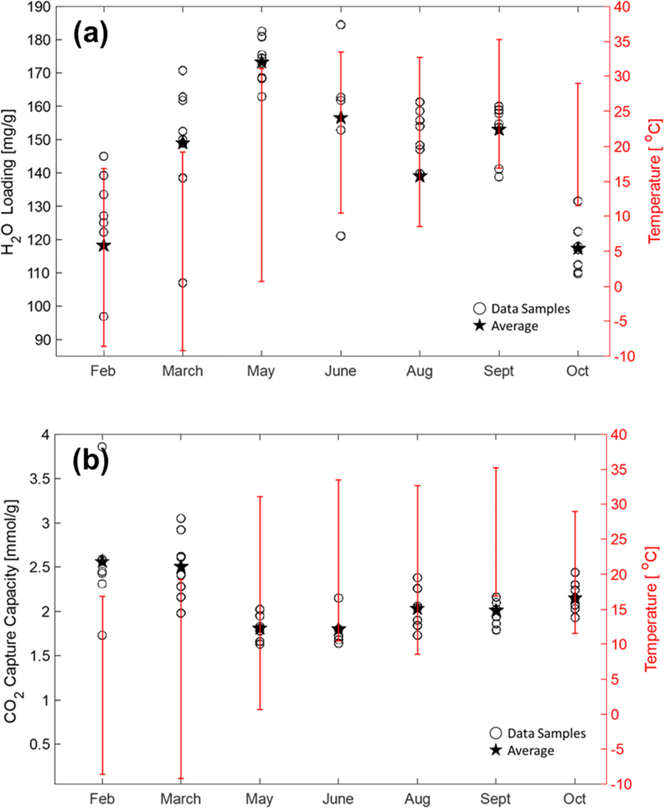 | ||
| Fig. 5 Results of monthly RTU H2O (a) and CO2 loading (b) from February to October 2022. | ||
For the CO2 loading test, the behavior of the PAN-TETA adsorbent during the CO2 loading test was the opposite of its behavior during the H2O loading test under the atmospheric temperature conditions, as shown in Fig. 5b. The lowest CO2 loadings of 1.62 and 1.64 mmol g−1 were observed during warm and humid times in May and June, whereas the highest CO2 loadings of 3.86 and 3.04 mmol g−1 occurred during the dry and cold conditions in February and March. The average CO2 loading during February was 20.1% higher than the annual average of 2.11 mmol g−1. Furthermore, the average CO2 loading for May was 14.7% lower than the annual average CO2 loading. The CO2 loading here is much higher than the loading tested in dry N2 (0.33 mmol g−1). The high loading is caused by the presence of moisture. It is reported that CO2 reacts with immobilized amine in the dry state and forms carbamate, whereas it forms bicarbonate in the presence of moisture.56 Therefore, the loading of CO2 in PAN-TETA increases in the presence of moisture.
The colder and drier geospatial regions were found to be favorable for PAN-TETA DAC performance in RTUs. These results agree with previous studies on amine-based sorbents used in DAC applications.12,57,58 However, ambient air conditions vary widely by location because of daily and seasonal variations. Consequently, the performance of RTU DAC applications is highly dependent on the weather fluctuations in their respective locations. One limitation of this research was that all collected data were for a fixed RTU location in Oak Ridge, Tennessee.
3.3 Techno-economic analysis on RTU applications
The final cost includes the cost of raw materials, chemical wastes, maintenance, outer structure, additional energy demand, and labor. The estimated cost of PAN-TETA material development for DAC is given in Table 3. The cost of producing 7.2 kg of adsorbent materials for RTU demonstration on a pilot scale was $3221.20 for 900 PAN-TETA sheets. The reactants, PAN and TETA, are commercially available in large quantities. Currently, the costs of PAN and TETA are respectively $15.89 per sheet and $8.65 per lb in small quantities, but these costs can be reduced when PAN and TETA are purchased in larger quantities for larger-scale production. The deionized water used in the reaction was produced in the lab using a deionized water system, and the cost was estimated. A large portion of the total cost (49.4%) came from the labor cost. However, labor costs will be much lower on a commercial scale; the scale for this study was quite small. Table 4 shows the estimated cost of the structural materials used for the RTU for CO2 capture. Table 5 displays the estimated cost of electricity, Table 6 displays the estimated cost of transportation, and Table 7 displays the estimated cost of material regeneration. Fig. 6 presents the hourly power consumption for the RTU with and without the modules over the year. The annual average power consumption for the RTU modules was 8.2 kW h, which is 24.9% higher than the annual average power consumption without the RTU modules (6.15 kW h). In this work, the following assumptions for the economic analysis were used:| Material cost per unit ($) | Unit | Unit usage | Cost ($) | Reference | |
|---|---|---|---|---|---|
| Top roof | 0.095 | in.2 | 672 | 63.84 | 1/16 in. 6061 Al sheets (McMaster) |
| Side wall | 0.095 | in.2 | 748 | 71.06 | 1/16 in. 6061 Al sheets (McMaster) |
| Mesh | 0.089 | in.2 | 3645 | 324.40 | Chemical-resistant polypropylene plastic mesh (McMaster) |
| Container | 4.875 | in.2 | 360 | 1755.00 | 6063 Al rectangular tube, 3/16 in. wall thickness, 4½ in. high × 4½ in. wide (McMaster) |
| L-shape sheet | 0.21 | in.2 | 152 | 31.92 | 1/4 in. 6061 Al sheets (McMaster) |
| T-slot frame | 1.05 | in.2 | 35 | 36.96 | T-slotted framing (McMaster) |
| Total | — | — | — | 2283.18 | — |
| Unit component | Unit | Unit usage | Cost ($) | Reference/note | |
|---|---|---|---|---|---|
| Mechanical convection oven | — | — | — | 1270.60 | 81 L capacity65 |
| Power consumption | 1.6 | kW h per cycle | — | — | For a 10 day cycle |
| Total cost for 5 years | — | — | — | 24.09 | For a 10 day cycle |
| Total cost for 10 years | — | — | — | 48.18 | For a 10 day cycle |
 | ||
| Fig. 6 Comparison of additional hourly power consumption with and without RTU modules for February to October 2022. | ||
• A 10 day cycle was assumed for the adsorbent PAN-TETA material.
• The CO2 loading was assumed to be 3 mmol g−1.
• The electricity usage was assumed to be 2.07 kW h during the 10 day cycle (Table 5).
• The electricity cost was estimated using the Annual Energy Outlook 2023 by the US Energy Information Administration (EIA).59
• The transportation distance was assumed to be 2 mi (Table 6).
• A convection oven was used for the sorbent regeneration (Table 7).
Diagrams of the levelized costs of CO2 capture for 5 and 10 years of operation are shown in Fig. 7. For 5 years of operation, the PAN-TETA material production is 40.6% of the total cost. To achieve $100/ton of CO2 levelized cost of CO2 capture, 42.5 t of CO2 per year is required for 5 years of analysis, and 30.5 t of CO2 per year is required for 10 years of operation, as shown in Fig. 8. These capacities are 265 times (5 years) and 190 times (10 years) greater, respectively, than the current CO2 capacity for a single RTU (0.16 t of CO2 per year). To achieve this capacity and cost target from the Carbon Negative Shot, increasing the number of installations of the RTU DAC is needed. In addition, the RTU analysis result was compared with the reported learning rates of Li-ion batteries (30%) and solar PV (23%).25,31 The one-factor learning curve is modeled as
| C(x) = axb, | (1) |
| LR = 1 − 2b, | (2) |
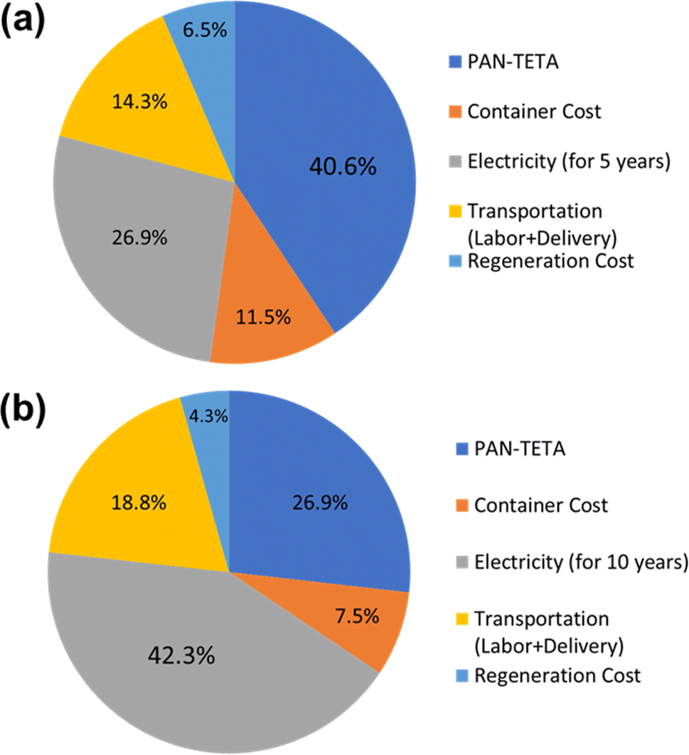 | ||
| Fig. 7 Breakdown of the cost of the RTU DAC modules for (a) 5 year analysis and (b) 10 year operation. | ||
 | ||
| Fig. 8 Levelized cost of CO2 capture based on assumed CO2 capture capacity: (a) 5 year analysis and (b) 10 year analysis. | ||
4. Summary and conclusions
DAC is a promising technology for reducing atmospheric CO2 levels. Many scientific groups recognize DAC as an essential and scalable approach that complements other climate actions. However, several challenges must be overcome to make DAC technology economically viable and environmentally sustainable. This study explored the potential of utilizing existing RTU technologies for DAC. Our research found that DAC technology integrated into an existing RTU could effectively capture atmospheric CO2 under varying weather conditions. However, the loading capacity of CO2 was significantly influenced by fluctuations in the atmospheric temperature and relative humidity throughout the year. The use of packed adsorbent materials increased power consumption by creating an added pressure drop, which could significantly affect the overall cost of RTU DAC. Additionally, how to utilize the captured CO2 is also an important factor in evaluating the DAC technology. We are working on utilizing the captured CO2 from RTU, including greenhouse enrichment, storage, and CO2 conversion into building materials.The cost of adsorbent materials was a major limitation during the 5 year analysis, accounting for 40.6% of the total cost. In the 10 year analysis, electricity cost occupied a larger proportion of the total cost (42.3%) due to the added pressure drop across the adsorbent structure. Thus, it is essential to optimize operational processes and develop efficient adsorbent materials to reduce the application cost of RTU DAC. The challenges and benefits of RTU DAC operation are highly specific and require further analysis to verify its CO2 capture performance and identify the most cost-effective solutions. In addition to the current removal cost, further research is needed on the capture of CO2 from RTU DAC after the regeneration step. The small-scale, dispersedly captured CO2 from the RTU DAC necessitates a smart network for collection, storage, or utilization. Encouragingly, scientists specializing in CO2 capture and utilization can contribute their expertise to this field. By advancing the use of materials for CO2 capture and utilization, the urgent need to mitigate climate change and its effects can be properly addressed.
In conclusion, the findings of our study suggest that RTU DAC technology has the potential of becoming an effective and scalable solution for capturing atmospheric CO2. However, the future development and co-optimization of efficient adsorbent materials and RTU operational control will be essential to reduce the deployment cost of RTU DAC. Further research is required to evaluate RTU DAC locations and their impact on cost-effectiveness. This analysis should consider multiple parameters, including climatic conditions, energy costs, storage/utilization expenses, and political incentives for building owners to adopt RTU DAC technology. Evaluating these dimensions will provide valuable insights into optimizing the deployment of RTU DAC systems and enhancing their economic viability. Additionally, a full boundary cradle-to-grave life cycle assessment that tracks all installation and manufacturing-related emissions is needed to evaluate the feasibility and sustainability. The current techno-economic analysis framework presented here can also be used to back-calculate the target adsorbent material cost/performance and the levelized cost of electricity to achieve the cost target of DAC identified in the Carbon Negative Shot with this approach. More importantly, this project demonstrated the importance of multi-disciplinary collaborations in addressing the pressing global issue, and hopefully it will inspire further adsorbent material innovation, RTU system design/control and more refined techno-economic analysis in a holistic and iterative manner to advance the field of DAC technologies.
Conflicts of interest
The authors declare that they have no known competing financial interests or personal relationships that could have appeared to influence the work reported in this paper.Acknowledgements
This research was supported by the DOE Office of Fossil Energy and Carbon Management (FECM) and used resources at the Building Technologies Research and Integration Center (BTRIC) and Manufacturing Demonstration Facility (MDF), DOE Office of Science User Facilities operated by the Oak Ridge National Laboratory. The authors would like to acknowledge the assistance of Brian Goins, Anthony Gehl, and Robert Nettles in the setup and performance of the testing.References
- S. Sikdar and F. Princiotta, Advances in Carbon Management Technologies: Carbon Removal, Renewable and Nuclear Energy, CRC Press, 2020, vol. 1 Search PubMed.
- M. Collins, R. Knutti, J. Arblaster, J.-L. Dufresne, T. Fichefet, P. Friedlingstein, X. Gao, W. J. Gutowski, T. Johns and G. Krinner, in Climate Change 2013-The Physical Science Basis: Contribution of Working Group I to the Fifth Assessment Report of the Intergovernmental Panel on Climate Change, Cambridge University Press, 2013, pp. 1029–1136 Search PubMed.
- S. Mal, R. B. Singh and C. Huggel, Climate Change, Extreme Events and Disaster Risk Reduction: towards Sustainable Development Goals, Springer International Publishing, 2017 Search PubMed.
- T. Bolch, A. Kulkarni, A. Kääb, C. Huggel, F. Paul, J. G. Cogley, H. Frey, J. S. Kargel, K. Fujita, M. Scheel, S. Bajracharya and M. Stoffel, Science, 2012, 336, 310–314 CrossRef CAS PubMed.
- C. B. Field, V. Barros, T. F. Stocker and Q. Dahe, Managing the Risks of Extreme Events and Disasters to Advance Climate Change Adaptation: Special Report of the Intergovernmental Panel on Climate Change, Cambridge University Press, 2012 Search PubMed.
- I. Ahmed and N. Das in Climate Change, Extreme Events and Disaster Risk Reduction: towards Sustainable Development Goals, ed. S. Mal, R. B. Singh and C. Huggel, Springer International Publishing, Cham, 2018, pp. 135–146 Search PubMed.
- D. Zolotov, D. Chernykh, R. Y. Biryukov and D. Pershin, in Climate Change, Extreme Events and Disaster Risk Reduction, Springer, 2018, pp. 147–157 Search PubMed.
- E. Milanova, A. Nikanorova, A. Kirilenko and N. Dronin, in Climate Change, Extreme Events and Disaster Risk Reduction: towards Sustainable Development Goals, ed. S. Mal, R. B. Singh and C. Huggel, Springer International Publishing, Cham, 2018, pp. 75–88 Search PubMed.
- A. Schick, E. Wieners, N. Schwab and U. Schickhoff, in Climate Change, Extreme Events and Disaster Risk Reduction: towards Sustainable Development Goals, ed. S. Mal, R. B. Singh and C. Huggel, Springer International Publishing, Cham, 2018, pp. 249–264, DOI:10.1007/978-3-319-56469-2_17.
- T. Beer, in Climate Change, Extreme Events and Disaster Risk Reduction, Springer, 2018, pp. 121–133 Search PubMed.
- J. Wang, R. Fu, S. Wen, P. Ning, M. H. Helal, M. A. Salem, B. B. Xu, Z. M. El-Bahy, M. Huang and Z. Guo, Adv. Compos. Hybrid Mater., 2022, 5, 2721–2759 CrossRef CAS.
- J. F. Wiegner, A. Grimm, L. Weimann and M. Gazzani, Ind. Eng. Chem. Res., 2022, 61, 12649–12667 CrossRef CAS.
- N. J. Williams, C. A. Seipp, F. M. Brethomé, Y.-Z. Ma, A. S. Ivanov, V. S. Bryantsev, M. K. Kidder, H. J. Martin, E. Holguin, K. A. Garrabrant and R. Custelcean, Chem, 2019, 5, 719–730 CAS.
- M. Fasihi, O. Efimova and C. Breyer, J. Cleaner Prod., 2019, 224, 957–980 CrossRef CAS.
- J. Kothandaraman, A. Goeppert, M. Czaun, G. A. Olah and G. K. Prakash, J. Am. Chem. Soc., 2016, 138, 778–781 CrossRef CAS PubMed.
- F. Barzagli, C. Giorgi, F. Mani and M. Peruzzini, ACS Sustainable Chem. Eng., 2020, 8, 14013–14021 CrossRef CAS.
- S. Mukherjee, N. Sikdar, D. O'Nolan, D. M. Franz, V. Gascón, A. Kumar, N. Kumar, H. S. Scott, D. G. Madden and P. E. Kruger, Sci. Adv., 2019, 5, eaax9171 CrossRef CAS.
- Z. Zhang, Q. Ding, J. Cui, X. Cui and H. Xing, Sci. China Mater., 2021, 64, 691–697 CrossRef.
- T. M. McDonald, W. R. Lee, J. A. Mason, B. M. Wiers, C. S. Hong and J. R. Long, J. Am. Chem. Soc., 2012, 134, 7056–7065 CrossRef CAS PubMed.
- N. R. Stuckert and R. T. Yang, Environ. Sci. Technol., 2011, 45, 10257–10264 CrossRef PubMed.
- H. Thakkar, A. Issa, A. A. Rownaghi and F. Rezaei, Chem. Eng. Technol., 2017, 40, 1999–2007 CrossRef CAS.
- J. V. Veselovskaya, V. S. Derevschikov, T. Y. Kardash, O. A. Stonkus, T. A. Trubitsina and A. G. Okunev, Int. J. Greenhouse Gas Control, 2013, 17, 332–340 CrossRef CAS.
- J. V. Veselovskaya, V. S. Derevschikov, A. S. Shalygin and D. A. Yatsenko, Microporous Mesoporous Mater., 2021, 310, 110624 CrossRef CAS.
- V. S. Derevschikov, J. V. Veselovskaya, T. Y. Kardash, D. A. Trubitsyn and A. G. Okunev, Fuel, 2014, 127, 212–218 CrossRef CAS.
- N. McQueen, K. V. Gomes, C. McCormick, K. Blumanthal, M. Pisciotta and J. Wilcox, Prog. Energy, 2021, 3, 032001 CrossRef.
- M. Bui and N. Mac Dowell, Greenhouse Gas Removal Technologies, Royal Society of Chemistry, 2022 Search PubMed.
- S. Shayegh, V. Bosetti and M. Tavoni, Front. Clim., 2021, 3, 630893 CrossRef.
- R. Hooper, How to Save the World for Just a Trillion Dollars: the Ten Biggest Problems We Can Actually Fix, the Experiment, 2022 Search PubMed.
- D. W. Keith, G. Holmes, D. S. Angelo and K. Heidel, Joule, 2018, 2, 1573–1594 CrossRef CAS.
- O. S. Board and E. National Academies of Sciences and Medicine, Negative Emissions Technologies and Reliable Sequestration: A Research Agenda, National Academies Press, 2019 Search PubMed.
- K. S. Lackner and H. Azarabadi, Ind. Eng. Chem. Res., 2021, 60, 8196–8208 CrossRef CAS.
- D. Soeder, in Energy Futures: the Story of Fossil Fuel, Greenhouse Gas, and Climate Change, Springer, 2022, pp. 205–239 Search PubMed.
- M. Z. Jacobson, Energy Environ. Sci., 2019, 12, 3567–3574 RSC.
- R. McDowall, Fundamentals of HVAC Systems: SI Edition, American Society of Heating, Refrigerating and Air-Conditioning Engineers eLearning, 2007 Search PubMed.
- M. Deru, M. Hayes, K. Vrabel, C. Burke, A. Jiron and C. Blazek, Long and Winding Road to Higher Efficiency—The RTU Story: Preprint, National Renewable Energy Laboratory, Golden, CO, 2021 Search PubMed.
- Capricorn, https://climeworks.com/roadmap/capricorn, accessed April 13, 2023.
- M. Schaus, Our Livable World: Creating the Clean Earth of Tomorrow, Diversion Books, 2020 Search PubMed.
- T. N. Y. T. E. Staff, Adapting to Climate Change, Rosen Publishing Group, 2019 Search PubMed.
- S. Deutz and A. Bardow, Nat. Energy, 2021, 6, 203–213 CrossRef CAS.
- G. A. Olah, A. Goeppert and G. K. S. Prakash, Beyond Oil and Gas: the Methanol Economy, Wiley, 2018 Search PubMed.
- M. M. Sadiq, M. P. Batten, X. Mulet, C. Freeman, K. Konstas, J. I. Mardel, J. Tanner, D. Ng, X. Wang, S. Howard, M. R. Hill and A. W. Thornton, Adv. Sustainable Syst., 2020, 4, 2000101 CrossRef CAS.
- S. Li, Y. Feng, Y. Li, S. Deng, X. E. Cao, K. B. Lee and J. Wang, Matter, 2024, 7, 889–933 CrossRef CAS.
- ASHRAE, 2020 ASHRAE Handbook – HVAC Systems and Equipment, American Society of Heating Refrigerating and Air-Conditioning Engineers Inc., SI Edition, 2020 Search PubMed.
- Trane, Packaged Rooftop Air Conditioners Precedent™ Cooling and Gas/Electric, 2021 Search PubMed.
- Trane, Packaged Rooftop Air Conditioners Voyager™ Light Commercial – Cooling, Gas/Electric, 2020 Search PubMed.
- JCI, R-410A SERIES 5 J**ZF/ZR/XP 3 – 6 TON 60 Hertz, 2012.
- JCI, ZX/ZY/ZQ/ZL SERIES 3 – 12.5 TON 60 HERTZ, 2020.
- JCI, SERIES 20 R-410A J**ZJ/ZR/ZF 15 – 25 TON 60 Hertz, 2017.
- P. Im, M. S. Bhandari and J. R. New, Multiyear Plan for Validation of EnergyPlus Multi-Zone HVAC System Modeling Using ORNL's Flexible Research Platform, United States, 2016 Search PubMed.
- S. J. A. DeWitt and R. P. Lively, Ind. Eng. Chem. Res., 2022, 61, 13612–13623 CrossRef CAS.
- M. Niu, H. Yang, X. Zhang, Y. Wang and A. Tang, ACS Appl. Mater. Interfaces, 2016, 8, 17312–17320 CrossRef CAS.
- R. Begag, H. Krutka, W. Dong, D. Mihalcik, W. Rhine, G. Gould, J. Baldic and P. Nahass, Greenhouse Gases: Sci. Technol., 2013, 3, 30–39 CrossRef CAS.
- J. D. Martell, P. J. Milner, R. L. Siegelman and J. R. Long, Chem. Sci., 2020, 11, 6457–6471 RSC.
- J. Elfving and T. Sainio, Chem. Eng. Sci., 2021, 246, 116885 CrossRef CAS.
- Y. Shi, Q. Liu and Y. He, in Handbook of Climate Change Mitigation and Adaptation, 2015, ch. 83-1, pp. 1–56 Search PubMed.
- C. Chen, S.-T. Yang, W.-S. Ahn and R. Ryoo, Chem. Commun., 2009, 3627–3629 RSC.
- G. Rim, F. Kong, M. Song, C. Rosu, P. Priyadarshini, R. P. Lively and C. W. Jones, JACS Au, 2022, 2, 380–393 CrossRef CAS PubMed.
- M. Sendi, M. Bui, N. Mac Dowell and P. Fennell, One Earth, 2022, 5, 1153–1164 CrossRef.
- Annual Energy Outlook, 2023, https://www.eia.gov/outlooks/aeo/, accessed 08-06-23.
- Deionized Water, https://www.chemcentral.com/solvents/deionized-water, accessed 08-06-23.
- Hazardous Waste Disposal Costs for Businesses, https://bouldercounty.gov/environment/hazardous-waste/disposal-costs-for-businesses/, accessed 08-06-23.
- Occupational Employment and Wages, https://www.bls.gov/oes/current/oes518091.htm, accessed 08-06-23.
- M. Slattery, J. Dunn and A. Kendall, Resour., Conserv. Recycl., 2021, 174, 105755 CrossRef.
- HVAC Pricing: How to Charge What You're Worth, https://business.nextdoor.com/en-us/small-business/resources/blog/hvac-pricing-how-to-charge-what-youre-worth, accessed 08-06-23.
- Mechanical Convection Oven, https://www.hogentogler.com/quincy-lab/40af-mechanical-convection-oven.asp, accessed 08-06-23.
Footnotes |
| † This manuscript has been authored by UT-Battelle, LLC, under contract DE-AC05-00OR22725 with the US Department of Energy (DOE). The US government retains and the publisher, by accepting the article for publication, acknowledges that the US government retains a nonexclusive, paid-up, irrevocable, worldwide license to publish or reproduce the published form of this manuscript, or allow others to do so, for US government purposes. The DOE will provide public access to these results of federally sponsored research in accordance with the DOE Public Access Plan (http://energy.gov/downloads/doe-public-access-plan). |
| ‡ Electronic supplementary information (ESI) available. See DOI: https://doi.org/10.1039/d4va00013g |
| § National Renewable Energy Laboratory, Golden, CO 80401, USA. |
| ¶ Chevron Richmond Technical Center, Richmond, VA 23230, USA. |
| This journal is © The Royal Society of Chemistry 2024 |