Molecular engineering of N,S-heteroarene-based small-molecule acceptors: effects of side chains, backbone extension and end groups on structure, optoelectronic properties and solar cell performance†
Gang
Wang
,
Xuejiao
Tang
,
Yalun
Zhao
,
Mingfan
Li
,
Pingping
Huang
,
Xiaoying
Zhang
,
Chao
Weng
and
Ping
Shen
 *
*
Key Laboratory for Green Organic Synthesis and Application of Hunan Province, Key Laboratory of Environmentally Friendly Chemistry and Application of Ministry of Education, College of Chemistry, Xiangtan University, Xiangtan 411105, China. E-mail: shenping802002@xtu.edu.cn
First published on 28th November 2023
Abstract
Studying the structure–property correlation of small-molecule acceptors (SMAs) is beneficial in optimizing their optoelectronic properties and enhancing photovoltaic performance. Here, we designed and synthesized six N,S-heteroarene (axa-indacenodithiophene, NIT)-based SMAs through molecular engineering (side chain, backbone extension and end group), which are defined as the pentacyclic central core series (NIT68, NIT810, and NIT810-F) and the backbone extension series (T-NIT68, NIT810-T, and NIT810-T-F), respectively. The results reveal that end group engineering (fluorination vs. non-fluorination) has a greater effect on the absorption properties and molecular energy levels as compared with side chain (2-hexyldecyl vs. 2-octyldodecyl) and backbone extension engineering. Theoretical calculation suggests that molecular engineering has a tiny impact on the backbone planarity of these NIT-based SMAs, but has a certain effect on the geometric configuration and electronic structure of molecules. Organic solar cells (OSCs) based on these SMAs were fabricated and device performance was optimized. OSCs based on the backbone extension series showed a higher open-circuit voltage (Voc) than those of the pentacyclic central core series, because of upshifted LUMOs. PBDB-T:NIT810-based OSCs exhibited the best power conversion efficiency (PCE) of 7.25% among these six SMAs. However, when PBDB-T was replaced by fluorinated PM6, the fluorinated NIT810-F and NIT810-T-F-based OSCs exhibited an improved PCE of up to 7.78% and 9.51%, respectively, due to the obviously increased fill factor (FF) and short-circuit current density (Jsc). The improved FF and Jsc should be primarily attributed to the increased exciton dissociation and charge transport properties, suppressed bimolecular recombination, and optimized phase separation. Our work focusing on the effect of molecular engineering on molecular structure, optoelectronic and photovoltaic properties will certainly provide some significant guidance for the molecular design of high-performance SMAs.
1. Introduction
After fullerene acceptors (e.g. PC71BM) were replaced by non-fullerene acceptors, such as ITIC,1 Y6,2 and N2200,3 the power conversion efficiencies (PCEs) of organic solar cells (OSCs) rapidly elevated. Currently, state-of-the-art OSCs produce PCEs of over 19% based on bulk-heterojunction (BHJ) blends containing nonfullerene small-molecule acceptors (SMAs) and polymer donors,4–12 which thereby are regarded as one of the promising approaches to achieve efficient solar energy utilization for future renewable energy source development.The outstanding device efficiency of SMAs mainly arises from their intramolecular donor–acceptor (D–A) structures, which can be realized by templated molecular design, typically including three parts: a ring-fused central core (D unit), an end group (A unit) and a side chain attached on the D unit.13–15 As for the A unit, 1,1-dicyano-methylene-3-indanone (IC) and its derivatives have received the most attention and are used widely due to their prominent electron-withdrawing characteristics, easy chemical modification, and excellent device performance.16–18 The side chain is usually an alkyl or alkoxy substituted aromatic ring in the D unit, which can tune the solubility, crystallinity, inter- and intra-molecular interaction and other properties of the resultant SMAs.13–15 Generally, there are four typical approaches to introducing a side chain onto the D unit: (i) by the sp3-hybridized carbon (C) atom of the cyclopentadiene moiety13–15 (e.g. ITIC1); (ii) by a sp2-hybridized carbon atom into aromatic ring19,20 (e.g. benzene ring or thiophene, see Y62); (iii) by the sp2-hybridized nitrogen (N) atoms into heteroaromatic ring14,21 (e.g. pyrrole, see Y6); and (iv) by introducing aryl-substituted methylene group into the cyclopentadiene moiety.22,23
The ring-fused D unit is commonly constructed from polycyclic heteroarenes containing a benzene ring and thiophene,13 for example, heptacyclic indacenodithienothiophene (IDTT) in ITIC.1 Besides, for Y-series SMAs, the ring-fused central core is formed by fusing an electron-deficient unit A′ (e.g. benzothiadiazole, see Y62) with electron-rich heteroacenes.14 Pyrrole is isoelectronic with thiophene and is likewise a promising building block for constructing the ring-fused central core.14,21,24 The electron-donating ability of pyrrole is stronger than that of thiophene, which is beneficial to enhancing the intramolecular D–A effect and thereby facilitating charge transfer, red-shifting absorption, and upshifting the lowest unoccupied molecular orbital (LUMO) level of the resultant materials.25 Additionally, the solubility, crystallinity and photo-electrochemical properties can be tailored by the introduction of a side chain on the N atom in pyrrole.
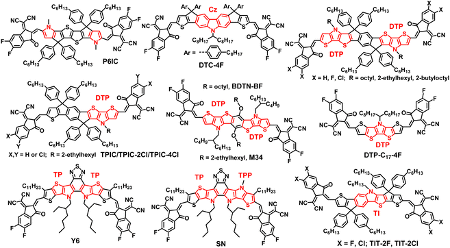
Zhan's group reported an N,S-heteroarene-based SMA P6IC (Fig. 1) with a hexacyclic D unit by fusing pyrrole with the two sides of thienothiophene. Compared with the thiophene-containing analogue, P6IC exhibited a red-shifted absorption spectrum, a reduced bandgap, an upshifted LUMO, increased carrier mobilities, and an obviously higher PCE of 12.2%.25 Carbazole (Cz) is a common tricyclic system containing pyrrole, which can be further fused with thiophene (DTC-4F, Fig. 1)26 or thienothiophene26 to form a polycyclic N,S-heteroarene D unit and the corresponding ITIC-like A–D–A acceptors with PCEs of over 15%.26 Tang and other groups developed a series of N,S-heteroarene-based A–D–A acceptors (see Fig. 1) with a nonacyclic D unit through the fusion of dithienopyrrole (DTP), cyclopentadiene and a benzene ring.27–31 After structural optimization (side chain27 and end group28,29 engineering) and device engineering (ternary device,28,30 binary solvent31), OSCs based on DTP-containing nonacyclic SMAs obtained the best PCEs of over 14%.28 Then, Yan and coworkers achieved an efficiency of over 15% by modulation of the end groups for the asymmetric SMAs (TPIC-2Cl/4Cl, Fig. 1) based on the DTP moiety.32 Yang et al. initiated two N,S-heteroarene-based SMAs with the same heptacyclic D unit by fusing two DTP moieties with one benzene ring directly, but different A groups.33 OSCs based on the SMA (BDTN-BF, Fig. 1) with a fluorinated IC as the A unit achieved the best PCE of 11.54% associated with the large open-circuit voltage (Voc) and high short-circuit current density (Jsc) simultaneously. Almost at the same time, Zheng and coworkers reported two novel SMAs based on different heteroheptacenes using the same synthesis strategy as that used for BDTN-BF. The chemical structure of DTP-based SMA (M34, Fig. 1) is the same as BDTN-BF except for the alkyl side chains attached to the N,S-heteroarene D unit.34 Finally, M34-based OSCs showed a dramatically improved PCE of 15.24% relative to BDTN-BF (PCE = 11.54%) with the same polymer donor PM6 mainly due to the increased Jsc and fill factor (FF), which stresses the importance of side chains. Compared with other polycyclic heteroarene-based D units, the new N,S-containing heptacyclic D unit is free of sp3-hybridized carbon atoms in the conjugated backbone, which is beneficial for enhancing π–π stacking and crystallinity, and thus increasing the carrier transport ability of the resulting SMAs.33,34 Besides this, Tan et al. developed a new sp3-hybridized C atom free N,S-heteroacene-based SMA (DTP-C17-4F, Fig. 1) with a pentacyclic D unit by fusing thiophene with the two sides of the DTP moiety.35 The obtained DTP-C17-4F demonstrated strong near-infrared absorption, and high electron mobility, resulting in a high Jsc of 21.17 mA cm−2 and a PCE of 8.94% for OSCs without additives.
In terms of N,S-heteroarene-based SMAs without a sp3-hybridized C atom in the conjugated backbone, the well-known Y6 (Fig. 1) is a milestone, and is called Y-series SMA.30 These SMAs possess a highly conjugated backbone with a new N,S-heteroarene-based central core by fusing electron-rich moieties on both sides of the electron-deficient moiety. In Y-series SMAs, the pyrrole ring is used to replace the cyclopentadiene moiety to form a thienopyrrole (TP) moiety. On the one hand, this can increase intramolecular push–pull charge transfer effects, and on the other hand it can reduce the steric hindrance due to only one side chain being attached on each nitrogen atom in the pyrrole ring. The uniquely multiple push–pull structure of Y-series SMAs results in some excellent and required structural and optoelectronic properties, which ultimately contribute outstanding solar cell performance.14,36 To further extend the absorption range, Zhu et al. developed an asymmetric SMA SN (Fig. 1) by replacing a thiophene ring with a pyrrole ring in the Y6 backbone. The resultant acceptor SN with an obviously redshifted absorption relative to Y6 exhibited a PCE of 14.3% for PM6-based binary devices and an improved PCE up to 17.5% for PM6:Y6-based ternary devices.37 Apart from the abovementioned SMAs, the Cao group reported new N,S-heteroarene-based heptacyclic SMAs (TIT-2F/2Cl, Fig. 1) by fusing thieno[3,2-b]indole (TI) with two thiophene rings. The resultant TI-based SMAs showed the best PCE of 14.46% in binary devices and 18.18% for ternary devices.38,39
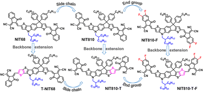
In view of the great potential of the N,S-heteroarene-based central core in constructing high-performance SMAs, we first design a N,S-heteroarene-based pentacyclic central D core: axa-indacenodithiophene (NIT), and then synthesized three A–D–A SMAs NIT68, NIT810, and NIT810-F based on the asymmetric NIT core through side chain and end group engineering. Finally, we further developed three corresponding SMAs T-NIT68, NIT810-T, and NIT810-T-F using axial backbone extension of the N,S-heteroarene-based core (NIT) by fusing one thiophene ring on the different direction of the NIT unit, as shown in Fig. 2. The findings demonstrate that (i) molecular engineering has a tiny impact on the backbone planarity of these NIT-based SMAs; (ii) end group engineering has a greater effect on the absorption properties and molecular energy levels as compared with side chain and backbone extension engineering; (iii) OSCs based on the backbone extension series (T-NIT68, NIT810-T, and NIT810-T-F) showed a higher Voc than those of the pentacyclic central core series (NIT68, NIT810, and NIT810-F); (iv) the end group fluorinated acceptors NIT810-F and NIT810-T-F paired with the fluorinated polymer donor PM6 can exhibit improved PCEs up to 7.78% and 9.51% compared with other donor–acceptor combinations, mainly due to the increased exciton dissociation and charge transport properties, suppressed bimolecular recombination, and superior active layer morphology. Our work focusing on the study of the structure–property relationship of SMAs would certainly provide some meaningful guidance for rational molecular design of efficient SMAs.
2. Experimental section
Some important materials, including 2,5-dibromonitrobenzene, ethyl-2-bromothiophene-3-carboxylate, 1-bromo-4-hexylbenzene, ethyl-2-bromothieno[3,2-b]thiophene-3-carboxylate, IC and its fluorinated derivative ICF, were purchased from commercial sources. The key for obtaining target molecules is the synthesis of dialdehyde intermediates (7a, 7b, 7b′, 14), which were synthesized by step-by-step reactions as shown in Scheme 1. Compounds 1, 2, 8, and 9 were synthesized according to previous reports.38 Six target SMAs were synthesized by the Knoevenagel condensation reaction between dialdehyde intermediates and the A group (IC, ICF) in the presence of pyridine. The details of synthesis of dialdehyde intermediates are provided in the ESI† and the target SMAs were synthesized as follows.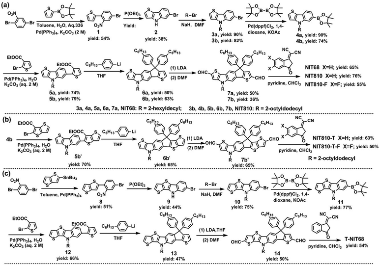 | ||
| Scheme 1 Synthetic routes of NIT-based SMAs: (a) NIT68, NIT810, and NIT810-F; (b) NIT810-T and NIT810-T-F; (c) T-NIT68. | ||
2.1 General synthetic procedure of target SMAs
Under an Ar atmosphere, dialdehyde intermediate (1 equiv.), IC or ICF (4 equiv.), pyridine (1 mL) and chloroform (30 mL) were added into a 100 mL round bottom flask in turn and then the mixture was stirred and refluxed for 12 h. After cooling to room temperature, the mixture was poured into methanol (100 mL) to obtain a precipitate as the crude product, which was further purified via silica gel column chromatography using petroleum ether/dichloromethane as the eluent to yield the target SMAs.3. Results and discussion
3.1 Design, synthesis and characterization of SMAs
As mentioned above, the end group (A), central core (D) and side chain all have a great effect on the molecular structure and basic properties of SMAs. We thus designed a series of NIT-based SMAs to systemically investigate the structure–property relationship. First, the model small molecule NIT68 is designed, where the N atom on the NIT unit is alkylated by 2-hexyldecyl. Next, side chain engineering is used to produce NIT810, in which 2-hexyldecyl is substituted by 2-octyldodecyl. Then, the third molecule NIT810-F is created via end group engineering with ICF replacing IC as the end group. In view of the fact that the above three SMAs contain a pentacyclic central D unit, they are called the pentacyclic central core series. Finally, three corresponding SMAs T-NIT68, NIT810-T, and NIT810-T-F are designed by axial backbone extension of the asymmetrical NIT core. As a result, these three SMAs belong to the backbone extension series. It should be noted that T-NIT68 is evolved by directly fusing one thiophene ring on the thieno[3,2-b]indole (TI) moiety into the NIT unit, whereas NIT810-T and NIT810-T-F are developed by directly fusing one thiophene ring of the indacenothiophene (IT) moiety into the NIT unit. The structural evolution process and chemical structures of six NIT-based SMAs are displayed in Fig. 2.The designed six SMAs were obtained according to three synthetic routes as displayed in Scheme 1. The pentacyclic central core series (NIT68, NIT810, and NIT810-F) were synthesized by similar steps with 2,5-dibromonitrobenzene as the starting material, which is subjected to Suzuki coupling (compound 1), Cadogan reductive cyclization (compound 2), N-alkylation (compound 3a, 3b), boric acid esterification (compound 4a, 4b), Suzuki coupling (compound 5a, 5b), intramolecular cyclization (compound 6a, 6b), Vilsmeier–Haack reaction (compound 7a, 7b) and Knoevenagel condensation in turn to yield the corresponding target molecules (see Scheme 1(a)). For NIT810-T and NIT810-T-F, compound 4b with 2-octyldodecyl as the side chain was coupled with ethyl-2-bromothieno[3,2-b]thiophene-3-carboxylate to yield compound 5b′, which was transformed into compound 6b′ with a fused hexacyclic backbone and then the target molecule was easily obtained by the following Vilsmeier–Haack reaction (compound 7b′) and Knoevenagel condensation in sequence, as shown in Scheme 1(b). Another target molecule T-NIT68 with the extended backbone was synthesized step-by-step using a procedure similar to NIT68 except for replacing the thiophene-2-boronic acid pinacol ester with 2-tributylstannyl-thieno[3,2-b]thiophene in the first coupling reaction as shown in Scheme 1(c). The synthetic details for all the intermediates are provided in the ESI† and synthesis and structural characterizations of the target SMAs are presented in the experimental section. Except for NIT810-F, other target molecules show good solubility in chloroform, dichloromethane, chlorobenzene and other common organic solvents under room temperature or heating up appropriately. NIT810-F has relatively poor solubility in chloroform compared with other SMAs, thus it is difficult to obtain a discernable 13C NMR spectrum. However, its solubility is enough to prepare a solar cell device with chloroform as the processing solvent.
The thermal decomposition temperature corresponding to a weight loss of 5% was revealed to be 328 °C by the TGA test (see Fig. S1a and b in the ESI†) for both T-NIT68 and NIT810-T, which is obviously lower than that of the other four SMAs (see Table 1). From differential scanning calorimetry (DSC) plots (Fig. S2a, ESI†), NIT68 just exhibits a weak melting peak (Tm) at about 200 °C in the second heating cycle, whereas NIT810 and NIT810-F show obviously endothermic peaks with a similar Tm at about 250 °C. In the first cooling cycle, NIT810 displays a crystallization thermal transition with a crystallization peak (Tc) at about 247 °C. However, the obvious crystallization thermal transition in the first cooling cycle cannot be found for both NIT68 and NIT810-F within the test temperature, which is similar to T-NIT68 and NIT810-T-F (see Fig. S2b, ESI†). In addition, one also can find a cold crystallization peak ( ) at about 199 °C for NIT810. Interesting, this phenomenon can also be observed for NIT810-T (
 ) as shown in Fig. S2b (ESI†). The simultaneous appearance of obvious Tm, Tc and
  indicates that NIT810 and NIT810-T should have better crystallinity than that of the other four SMAs. This seems to mean that side chain engineering is more effective to tailor the crystallization properties compared with end group engineering and backbone extension.
| SMA | T d (°C) | T m (°C) | T c (°C) |
λ
sol.max
![[thin space (1/6-em)]](https://www.rsc.org/images/entities/char_2009.gif) (nm)
(nm) |
λ
filmmax
![[thin space (1/6-em)]](https://www.rsc.org/images/entities/char_2009.gif) (nm)
(nm) |
λ edge (nm) |
E
optg
![[thin space (1/6-em)]](https://www.rsc.org/images/entities/char_2009.gif) (eV)
(eV) |
HOMOh (eV) | LUMOh (eV) |
|---|---|---|---|---|---|---|---|---|---|
| a The 5% weight-loss temperatures measured by TGA. b The melting peak measured by DSC. c The crystallization peak measured by DSC. d Measured in dilute chloroform solution. e Measured in a thin film. f Absorption edge of the thin films. g Estimated from the absorption edge: Eoptg = 1240/λedge. h Gained from CV measurement based on the equation: HOMO/LUMO = −e(Eox/red + 4.38) (eV). | |||||||||
| NIT68 | 367 | 200 | — | 670 | 693 | 787 | 1.58 | −5.68 | −3.86 |
| NIT810 | 349 | 249 | 247 | 675 | 701 | 762 | 1.57 | −5.67 | −3.85 |
| NIT810-F | 366 | 250 | — | 682 | 712 | 790 | 1.63 | −5.74 | −3.94 |
| T-NIT68 | 328 | 239 | — | 610 | 635 | 757 | 1.64 | −5.59 | −3.63 |
| NIT810-T | 328 | 238 | 209 | 686 | 727 | 801 | 1.55 | −5.61 | −3.61 |
| NIT810-T-F | 372 | 233 | — | 696 | 739 | 818 | 1.52 | −5.70 | −3.66 |
3.2 Absorption properties and HOMO/LUMO energy levels of SMAs
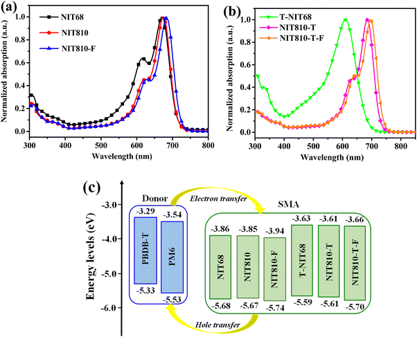
As shown in Fig. 3(a), NIT68, NIT810, and NIT810-F in dilute chloroform solution have similar absorption outlines with the main absorption in the range of 500–720 nm. The maximum absorption peak (λsol.max) corresponding to the intramolecular charge transfer (ICT) effect between D and A units is gradually red-shifted from NIT68 (670 nm) to NIT810 (675 nm), then to NIT810-F (682 nm), as listed in Table 1. A similar result can be observed from T-NIT68 (610 nm) to NIT810-T (686 nm) and to NIT810-T-F (696 nm), as shown in Fig. 3(b) and Table 1. These results suggest that the introduction of a more bulky alkyl chain and fluorinated end group (ICF) can efficiently red-shift the absorption spectra of these NIT-based A–D–A molecules. On the other hand, one can find that the λsol.max of NIT810-T and NIT810-T-F are red-shifted as comparison with NIT810 and NIT810-F, respectively, which should be ascribed to the extension of the conjugated molecular backbone. Surprisingly, the λsol.max of T-NIT68 is obviously blue-shifted relative to NIT68. This opposite result indicates that the different extension direction (thieno[3,2-b]indole and indacenothiophene) of the NIT unit has a different impact on the absorption spectra of these NIT-based SMAs, which will be discussed in the following section. From the solution to solid thin film (Fig. S3, ESI†), the maximum absorption peaks (λfilmmax) are red-shifted and the absorption spectra are broadened for all six SMAs, which could be attributed to molecule aggregation in the solid state. Another piece of evidence is the appearance of obvious shoulder peaks except for T-NIT68. In particular, the absorption intensity of the shoulder peaks of NIT68 and NIT810-F are even evidently higher than those of λfilmmax originating from the ICT effect, which implies that shortening the alkyl chain and fluorination on the end group can enhance the molecular aggregation in solid films. As observed in the solution, one can also find an opposite change in the trend of the λfilmmax of NIT68 relative to T-NIT68 and the other two counterparts (NIT810versusNIT810-T; NIT810-FversusNIT810-T-F). Some similar results of blue-shifted absorption resulting from extending the conjugated backbone have been revealed in previous reports.1–3 We speculate that this unusual phenomenon (T-NIT68versusNIT68) could be explained from two aspects. One possible explanation is that the extended conjugation of the aromatic backbone in T-NIT68 leads to a decrease in solubility due to the relatively small alkyl chain on the N atom (2-hexyldecyl versus 2-octyldodecyl), which suppresses the formation of ordered domains during the rapid film-formation process.40 The other reason may be ascribed to the different electronic structure of T-NIT68 relative to NIT810-T and NIT810-T-F,41,42 which will be discussed in the next section. The optical bandgap (Eoptg) of these SMAs obtained from the absorption edge of the thin films (λedge, see Table 1) is 1.52–1.64 eV (Table 1), indicating that side chains, backbone extension and end groups play a key role in regulating the bandgaps of A–D–A type SMAs. Moreover, we also find that the Eoptgs of these NIT-based SMAs are lower than those of analogs based on the indacenodithiophene (IDT) unit.43,44 This suggests that the introduction of the N atom into the IDT unit can redshift the absorption spectra and reduce bandgaps. The relatively low Eoptg means that these NIT-based materials are suitable for matching with wide or medium bandgap donor materials to achieve a high Jsc.HOMO/LUMO energy levels of these SMAs were obtained by cyclic voltammetry (CV) measurement. We obtained CV plots (see Fig. S4 in the ESI†) of these SMAs to gain the first onset oxidation/reduction potentials (Eonsetox/red) of small molecules and then calculated the corresponding HOMO/LUMO energy levels via the equation: HOMO/LUMO = −e(Eonsetox/red + 4.38) (eV). The details of the CV measurement can be found in the ESI† and the relevant data are listed in Table 1. The HOMO and LUMO energy levels of NIT68 are determined to be −5.68 and −3.86 eV, respectively, which are similar to NIT810, but are higher than those of NIT810-F (see Table 1). For the backbone extension series (T-NIT68, NIT810-T, and NIT810-T-F), similar results are observed as listed in Table 1. These results imply that end group engineering has a greater effect on tailoring the molecular energy levels than side chain engineering. On the other hand, as shown in Table 1, both the HOMO and LUMO energy levels of T-NIT68, NIT810-T, and NIT810-T-F are higher than those of NIT68, NIT810, and NIT810-F, respectively, indicating conjugated backbone extension of the D unit can effectively up-shift the molecular energy levels of A–D–A SMAs. The higher-lying LUMO level is conducive to obtaining a larger Voc. To analyze the possibility of charge transfer between the polymer donor and these SMAs, the HOMO/LUMO of these NIT-based SMAs and two polymer donors (PBDB-T and PM6) are arranged in Fig. 3(c). Both HOMO and LUMO levels of all six NIT-based SMAs are lower than those of polymer donors (PBDB-T and PM6), which could provide a sufficient driving force for charge transfer (electron and hole) between the polymer donors and SMAs. This ensures the generation of photocurrent in BHJ blends based on these polymer donors and SMAs.
3.3 Theoretical approach
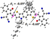
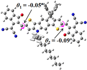
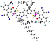
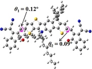
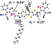
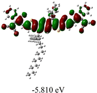
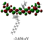
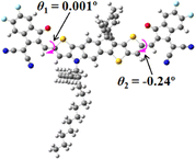
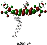
We next studied the effect of molecular engineering (side chain, backbone extension and end group) of these NIT-based SMAs on the molecular configuration and optoelectronic properties using theoretical approaches. The geometries and electron distributions of these molecules were simulated by density functional theory (DFT) based on the B3LYP/3-21G(d) level. To save calculation time, hexyl on benzene is simplified to be methyl; however, a long alkyl chain attached to the N atom is maintained with the aim of inspecting the influence of side chain engineering, as displayed in Table 2. From the optimal geometries of these molecules, one can find that all six NIT-based SMAs possess excellent backbone coplanarity: the dihedral angles (θ1, θ2) between the NIT-based pentacyclic or hexacyclic central core and the terminal A group (IC or ICF) are near to zero on the both sides of the central unit. This observation suggests that molecular engineering (side chain, backbone extension and end group engineering) has a limited impact on the backbone planarity of these NIT-based SMAs. A nearly planar backbone structure is beneficial to enhance the π–π stacking and molecular packing in the solid state, thus resulting in red-shifted absorption spectra and improved charge transport ability. As shown in Table 2 (top view), one can find that the pentacyclic central core series (NIT68, NIT810, and NIT810-F) have an S-shape molecular geometry, whereas the backbone extension series (T-NIT68, NIT810-T, and NIT810-T-F) exhibit a C-shape molecular geometry. The different molecular geometry should stem from the fact that the S atoms from thiophene ends in the NIT-based pentacyclic or hexacyclic central core can form intramolecular noncovalent interactions with O atoms from IC or ICF, which can afford a planar backbone structure.45–49 Although three acceptors of T-NIT68, NIT810-T, and NIT810-T-F possess the same molecular geometry, their specific molecular and electronic structures are different. The orientation of the bulky alkyl chain (2-hexyldecyl) on the N atom and C![[double bond, length as m-dash]](https://www.rsc.org/images/entities/char_e001.gif) O group in the terminal IC unit of T-NIT68 is on the same side, whereas for NIT810-T and NIT810-T-F, the two parts are on opposite sides. This difference should affect intermolecular π–π interactions and hence molecular aggregation. As a result, the blue-shifted absorption spectrum of T-NIT68 indicates that it should have H-aggregation in the solid state, while both NIT810-T and NIT810-T-F should have J-aggregation in the solid state.
O group in the terminal IC unit of T-NIT68 is on the same side, whereas for NIT810-T and NIT810-T-F, the two parts are on opposite sides. This difference should affect intermolecular π–π interactions and hence molecular aggregation. As a result, the blue-shifted absorption spectrum of T-NIT68 indicates that it should have H-aggregation in the solid state, while both NIT810-T and NIT810-T-F should have J-aggregation in the solid state.
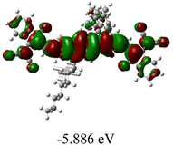
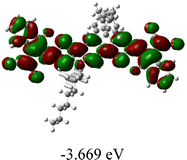
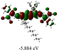
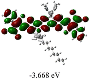
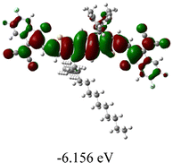
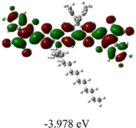
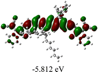
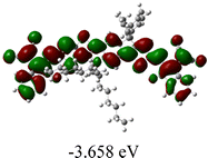
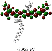
As shown in Table 2, in all six cases, electron density distributions of the HOMO levels are predominantly delocalized from the NIT-based central D unit to the A unit (IC or ICF) to some extent, whereas electron density distributions of the LUMO levels are mainly delocalized along the whole conjugated molecular backbone from D to A units, which is indicative of a very efficient ICT effect in these A–D–A systems. Theoretically calculated HOMO levels of all SMAs are generally lower than those deduced from the CV results, while LUMO levels are generally higher, as listed in Table 2. However, the changes in these calculated HOMO/LUMOs coincide with those obtained from the CV results (Table 1).
3.4 Photovoltaic properties of these NIT-based SMAs
To evaluate the photovoltaic properties of these NIT-based materials, we fabricated BHJ OSCs using these NIT-based molecules as acceptors and well-known medium-bandgap polymer PBDB-T or PM6 as the donor material.50,51 Details of the photovoltaic device fabrication and performance test are provided in the ESI.† Several common means, including the ratio of donor and acceptor (donor![[thin space (1/6-em)]](https://www.rsc.org/images/entities/char_2009.gif) :
:![[thin space (1/6-em)]](https://www.rsc.org/images/entities/char_2009.gif) acceptor), thermal annealing (TA), additive, polymer donor type (PBDB-T, PM6), were applied to optimize the photovoltaic properties of OSCs and the corresponding device performance results are provided in Tables S1–S6 in the ESI.† The photovoltaic parameters of optimized OSCs based on these SMAs are summarized in Table 3. Pairing with PBDB-T, the NIT68-based device shows a PCE of 6.63% with a donor
acceptor), thermal annealing (TA), additive, polymer donor type (PBDB-T, PM6), were applied to optimize the photovoltaic properties of OSCs and the corresponding device performance results are provided in Tables S1–S6 in the ESI.† The photovoltaic parameters of optimized OSCs based on these SMAs are summarized in Table 3. Pairing with PBDB-T, the NIT68-based device shows a PCE of 6.63% with a donor![[thin space (1/6-em)]](https://www.rsc.org/images/entities/char_2009.gif) :
:![[thin space (1/6-em)]](https://www.rsc.org/images/entities/char_2009.gif) acceptor ratio of 1
acceptor ratio of 1![[thin space (1/6-em)]](https://www.rsc.org/images/entities/char_2009.gif) :
:![[thin space (1/6-em)]](https://www.rsc.org/images/entities/char_2009.gif) 1 and TA under 110 °C for 10 min. Using the same donor (PBDB-T), the NIT810-based device obtains a higher PCE up to 7.25% with a donor
1 and TA under 110 °C for 10 min. Using the same donor (PBDB-T), the NIT810-based device obtains a higher PCE up to 7.25% with a donor![[thin space (1/6-em)]](https://www.rsc.org/images/entities/char_2009.gif) :
:![[thin space (1/6-em)]](https://www.rsc.org/images/entities/char_2009.gif) acceptor ratio of 1
acceptor ratio of 1![[thin space (1/6-em)]](https://www.rsc.org/images/entities/char_2009.gif) :
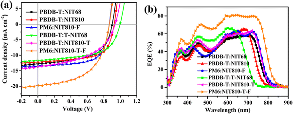
:![[thin space (1/6-em)]](https://www.rsc.org/images/entities/char_2009.gif) 1.5 and 1,8-diidooctane (DIO) as the additive. The improved PCE is mainly ascribed to the increased Voc (0.93 V) and FF (63.5%). In view of the relatively high PCE of the NIT810-based device compared with NIT68, the polymer donor PM6 was used to pair with NIT810 to further improve device performance due to its lower-lying HOMO energy level compared with PBDB-T. As expected, an increased Voc (0.97 V) is achieved along with a slightly increased Jsc (12.51 mA cm−2), but a sharply dropped FF (44.8%) is obtained, which finally leads to a reduced PCE of 5.44%. However, after PM6 replaces PBDB-T as the donor, the PCE of the NIT810-F-based device is obviously improved from 4.17% to 7.78%, due to the simultaneous increase of Voc, Jsc, and FF (see Table 3). These opposite results demonstrate that different SMAs need to pair with different donors to obtain superior photovoltaic performance. Using the same optimization means, the PCE of T-NIT68-, NIT810-T-, and NIT810-T-F-based devices is 6.84%, 6.26%, and 3.89%, respectively, with PBDB-T as the donor. Similar to NIT810-F, the PM6:NIT810-T-F-based device also exhibits a dramatically increased PCE up to 9.51% relative to the PBDB-T:NIT810-T-F-based device (3.89%). The current density–voltage (J–V) plots of the best OSCs based on six SMAs are depicted in Fig. 4(a). For the same polymer donor (e.g. PBDB-T), the Jsc of different NIT-based SMAs is consistent with the corresponding absorption spectra (see Fig. S3a and b, ESI†). The external quantum efficiency (EQE) spectra of the best OSCs based on six SMAs are measured to verify the Jscs, as shown in Fig. 4(b). The spectral coverage of the EQE plots depend on the absorption profiles of both SMAs and polymer donors. For the PM6:NIT810-T-F-based device, the maximum EQE is over 80% and the photoresponsive edge is close to 850 nm, thereby contributing the highest Jsc among these devices. Whereas, for the PBDB-T:T-NIT68-based device, the obviously blue-shifted photoresponsive edge should be responsible for its lowest Jsc. For the devices based on the other four SMAs, there is no big difference in the spectral response coverage of EQE plots, thus resulting in similar Jsc values. Overall, the integrated current from EQE is coincident with the Jsc obtained from J–V curves within a reasonable error range (see Table 3).
1.5 and 1,8-diidooctane (DIO) as the additive. The improved PCE is mainly ascribed to the increased Voc (0.93 V) and FF (63.5%). In view of the relatively high PCE of the NIT810-based device compared with NIT68, the polymer donor PM6 was used to pair with NIT810 to further improve device performance due to its lower-lying HOMO energy level compared with PBDB-T. As expected, an increased Voc (0.97 V) is achieved along with a slightly increased Jsc (12.51 mA cm−2), but a sharply dropped FF (44.8%) is obtained, which finally leads to a reduced PCE of 5.44%. However, after PM6 replaces PBDB-T as the donor, the PCE of the NIT810-F-based device is obviously improved from 4.17% to 7.78%, due to the simultaneous increase of Voc, Jsc, and FF (see Table 3). These opposite results demonstrate that different SMAs need to pair with different donors to obtain superior photovoltaic performance. Using the same optimization means, the PCE of T-NIT68-, NIT810-T-, and NIT810-T-F-based devices is 6.84%, 6.26%, and 3.89%, respectively, with PBDB-T as the donor. Similar to NIT810-F, the PM6:NIT810-T-F-based device also exhibits a dramatically increased PCE up to 9.51% relative to the PBDB-T:NIT810-T-F-based device (3.89%). The current density–voltage (J–V) plots of the best OSCs based on six SMAs are depicted in Fig. 4(a). For the same polymer donor (e.g. PBDB-T), the Jsc of different NIT-based SMAs is consistent with the corresponding absorption spectra (see Fig. S3a and b, ESI†). The external quantum efficiency (EQE) spectra of the best OSCs based on six SMAs are measured to verify the Jscs, as shown in Fig. 4(b). The spectral coverage of the EQE plots depend on the absorption profiles of both SMAs and polymer donors. For the PM6:NIT810-T-F-based device, the maximum EQE is over 80% and the photoresponsive edge is close to 850 nm, thereby contributing the highest Jsc among these devices. Whereas, for the PBDB-T:T-NIT68-based device, the obviously blue-shifted photoresponsive edge should be responsible for its lowest Jsc. For the devices based on the other four SMAs, there is no big difference in the spectral response coverage of EQE plots, thus resulting in similar Jsc values. Overall, the integrated current from EQE is coincident with the Jsc obtained from J–V curves within a reasonable error range (see Table 3).
| Active layer | TA (°C) | Additive (vol%) | V oc (V) | J sc (mA cm−2) | FF (%) | PCEb (%) |
|---|---|---|---|---|---|---|
| a The Jsc in brackets is integrated from EQE plots. b The PCE in brackets is an averaged value over four devices. c The total concentration of donor and acceptor was 20 mg mL−1 in CB. d The total concentration of donor and acceptor was 14 mg mL−1 in CF. e The total concentration of donor and acceptor was 10 mg mL−1 in CF. | ||||||
PBDB-T![[thin space (1/6-em)]](https://www.rsc.org/images/entities/char_2009.gif) : :![[thin space (1/6-em)]](https://www.rsc.org/images/entities/char_2009.gif) NIT68 = 1 NIT68 = 1![[thin space (1/6-em)]](https://www.rsc.org/images/entities/char_2009.gif) : :![[thin space (1/6-em)]](https://www.rsc.org/images/entities/char_2009.gif) 1c 1c |
110 °C | — | 0.90 | 12.73 (12.42) | 57.9 | 6.63 (6.48 ± 0.15) |
PBDB-T![[thin space (1/6-em)]](https://www.rsc.org/images/entities/char_2009.gif) : :![[thin space (1/6-em)]](https://www.rsc.org/images/entities/char_2009.gif) NIT810 = 1 NIT810 = 1![[thin space (1/6-em)]](https://www.rsc.org/images/entities/char_2009.gif) : :![[thin space (1/6-em)]](https://www.rsc.org/images/entities/char_2009.gif) 1.5d 1.5d |
— | 0.5 DIO | 0.93 | 12.28 (11.97) | 63.5 | 7.25 (7.10 ± 0.09) |
PM6![[thin space (1/6-em)]](https://www.rsc.org/images/entities/char_2009.gif) : :![[thin space (1/6-em)]](https://www.rsc.org/images/entities/char_2009.gif) NIT810 = 1 NIT810 = 1![[thin space (1/6-em)]](https://www.rsc.org/images/entities/char_2009.gif) : :![[thin space (1/6-em)]](https://www.rsc.org/images/entities/char_2009.gif) 1.5e 1.5e |
110 °C | — | 0.97 | 12.51 | 44.8 | 5.44 (5.29 ± 0.14) |
PBDB-T![[thin space (1/6-em)]](https://www.rsc.org/images/entities/char_2009.gif) : :![[thin space (1/6-em)]](https://www.rsc.org/images/entities/char_2009.gif) NIT810-F = 1 NIT810-F = 1![[thin space (1/6-em)]](https://www.rsc.org/images/entities/char_2009.gif) : :![[thin space (1/6-em)]](https://www.rsc.org/images/entities/char_2009.gif) 1.5d 1.5d |
110 °C | — | 0.79 | 12.17 | 43.4 | 4.17 (4.01 ± 0.12) |
PM6![[thin space (1/6-em)]](https://www.rsc.org/images/entities/char_2009.gif) : :![[thin space (1/6-em)]](https://www.rsc.org/images/entities/char_2009.gif) NIT810-F = 1 NIT810-F = 1![[thin space (1/6-em)]](https://www.rsc.org/images/entities/char_2009.gif) : :![[thin space (1/6-em)]](https://www.rsc.org/images/entities/char_2009.gif) 1.5e 1.5e |
110 °C | 0.5 DIO | 0.87 | 13.51 (13.15) | 66.2 | 7.78 (7.48 ± 0.37) |
PBDB-T![[thin space (1/6-em)]](https://www.rsc.org/images/entities/char_2009.gif) : :![[thin space (1/6-em)]](https://www.rsc.org/images/entities/char_2009.gif) T-NIT68 = 1 T-NIT68 = 1![[thin space (1/6-em)]](https://www.rsc.org/images/entities/char_2009.gif) : :![[thin space (1/6-em)]](https://www.rsc.org/images/entities/char_2009.gif) 1.2c 1.2c |
— | 0.5 DIO | 1.00 | 11.75 (11.41) | 58.2 | 6.84 (6.65 ± 0.15) |
PBDB-T![[thin space (1/6-em)]](https://www.rsc.org/images/entities/char_2009.gif) : :![[thin space (1/6-em)]](https://www.rsc.org/images/entities/char_2009.gif) NIT810-T = 1 NIT810-T = 1![[thin space (1/6-em)]](https://www.rsc.org/images/entities/char_2009.gif) : :![[thin space (1/6-em)]](https://www.rsc.org/images/entities/char_2009.gif) 1.2c 1.2c |
— | 2.0 CN | 0.94 | 13.73 (13.43) | 48.5 | 6.26 (6.07 ± 0.11) |
PBDB-T![[thin space (1/6-em)]](https://www.rsc.org/images/entities/char_2009.gif) : :![[thin space (1/6-em)]](https://www.rsc.org/images/entities/char_2009.gif) NIT810-T-F = 1 NIT810-T-F = 1![[thin space (1/6-em)]](https://www.rsc.org/images/entities/char_2009.gif) : :![[thin space (1/6-em)]](https://www.rsc.org/images/entities/char_2009.gif) 1.5d 1.5d |
130 °C | — | 0.84 | 12.90 | 35.9 | 3.89 (3.68 ± 0.26) |
PM6![[thin space (1/6-em)]](https://www.rsc.org/images/entities/char_2009.gif) : :![[thin space (1/6-em)]](https://www.rsc.org/images/entities/char_2009.gif) NIT810-T-F = 1 NIT810-T-F = 1![[thin space (1/6-em)]](https://www.rsc.org/images/entities/char_2009.gif) : :![[thin space (1/6-em)]](https://www.rsc.org/images/entities/char_2009.gif) 1.5e 1.5e |
130 °C | — | 0.87 | 19.73 (19.15) | 55.4 | 9.51 (9.31 ± 0.20) |
In terms of Voc, it is mainly related to the LUMO energy level of the acceptor and the HOMO level of the donor in a BHJ blend. Reducing the HOMO level of a donor or/and upshifting the LUMO level of an acceptor is beneficial to increase the Voc in BHJ OSCs. As a result, among the pentacyclic central core series (NIT68, NIT810, and NIT810-F), NIT810-F has the lowest LUMO level (see Table 1 or Fig. 2(c)), which should be responsible for the lowest Voc (0.79 V) of the NIT810-F-based devices. For the same reason, the NIT810-T-F-based device also shows the lowest Voc (0.84 V) in the backbone extension series (T-NIT68, NIT810-T, and NIT810-T-F). Pairing with the same acceptor, the improved Voc of PM6-based devices could be attributed to its higher-lying HOMO level relative to PBDB-T (Fig. 2(c)). In addition, the larger Voc of OSCs based on the backbone extension series also agrees with their higher LUMO levels (Table 1 or Fig. 2(c)) as compared with the pentacyclic central core series (NIT68, NIT810, and NIT810-F).
As shown in Table 3, NIT68, NIT810, T-NIT68, and NIT810-T should pair with PBDB-T to realize superior photovoltaic performance, while fluorinated acceptors of NIT810-F and NIT810-T-F blending with the fluorinated donor PM6 can achieve a higher PCE than that of PBDB-T. Consequently, we next selected these six optimized OSCs to explore the reasons for the differences in their photovoltaic performance. First of all, we studied the photo-induced charge transfer process between the polymer donor and SMA by obtaining the photoluminescence (PL) spectra of pure polymer films and donor![[thin space (1/6-em)]](https://www.rsc.org/images/entities/char_2009.gif) :
:![[thin space (1/6-em)]](https://www.rsc.org/images/entities/char_2009.gif) acceptor blend films. As shown in Fig. S5a (ESI†), the pure PBDB-T and PM6 films excited at 630 and 590 nm respectively, exhibit a strong PL spectrum in the range of 650–850 nm with a maximum emission peak at around 720 nm. The intensity of the maximum emission peak (∼720 nm) of the pure PBDB-T film is apparently quenched at about 98.5%, 97.5%, 91%, and 99.1% for the NIT68, NIT810, T-NIT68, and NIT810-T-based blend films, respectively, suggesting the occurrence of more efficient charge transfer from PBDB-T to NIT68 and NIT810-T relative to the other two acceptors (see Fig. S5b, ESI†). On the other hand, the intensity of the maximum emission peak of PM6 (∼720 nm) is more completely quenched after blending with NIT810-F (99.0%) and NIT810-T-F (99.4%), implying there is more efficient electron transfer from PM6 to the SMAs (NIT810-F and NIT810-T-F) with respect to PBDB-T (see Fig. S5b, ESI†). Efficient charge transfer between the polymer donor and acceptor is beneficial for obtaining a high photocurrent, which is generally consistent with the Jsc values of these six optimized devices (Table 3).
acceptor blend films. As shown in Fig. S5a (ESI†), the pure PBDB-T and PM6 films excited at 630 and 590 nm respectively, exhibit a strong PL spectrum in the range of 650–850 nm with a maximum emission peak at around 720 nm. The intensity of the maximum emission peak (∼720 nm) of the pure PBDB-T film is apparently quenched at about 98.5%, 97.5%, 91%, and 99.1% for the NIT68, NIT810, T-NIT68, and NIT810-T-based blend films, respectively, suggesting the occurrence of more efficient charge transfer from PBDB-T to NIT68 and NIT810-T relative to the other two acceptors (see Fig. S5b, ESI†). On the other hand, the intensity of the maximum emission peak of PM6 (∼720 nm) is more completely quenched after blending with NIT810-F (99.0%) and NIT810-T-F (99.4%), implying there is more efficient electron transfer from PM6 to the SMAs (NIT810-F and NIT810-T-F) with respect to PBDB-T (see Fig. S5b, ESI†). Efficient charge transfer between the polymer donor and acceptor is beneficial for obtaining a high photocurrent, which is generally consistent with the Jsc values of these six optimized devices (Table 3).
Then, we investigated the charge carrier mobility of the donor![[thin space (1/6-em)]](https://www.rsc.org/images/entities/char_2009.gif) :
:![[thin space (1/6-em)]](https://www.rsc.org/images/entities/char_2009.gif) acceptor blend film, including the electron and hole mobilities, by using the space-charge limited current (SCLC) method as shown in Fig. S6 (ESI†). The obtained electron and hole mobilities (μh and μe) data are summarized in Table S7 (ESI†). The PBDB-T:T-NIT68 and PBDB-T:NIT810-T blend films show lower μh (2.06 × 10⁻⁴ and 9.41 × 10⁻⁵ cm2 V−1 s−1) and μe (1.14 × 10⁻⁴ and 4.40 × 10⁻⁵ cm2 V−1 s−1) than those of the other four blend films, and relatively larger μh/μe values of 2.19 and 2.59, are gained respectively, which would be detrimental to their FF values. On the other hand, higher μh (3.48 × 10⁻⁴ and 4.21 × 10⁻⁴ cm2 V−1 s−1) and μe (2.01 × 10⁻⁴ and 2.82 × 10⁻⁴ cm2 V−1 s−1) values of the PM6:NIT810-F and PM6:NIT810-T-F blend films are observed respectively, as compared with the other four blend films. Moreover, smaller μh/μe values (1.73 and 1.49) are obtained for these two blend films, suggesting a more balanced charge carrier transport characteristic. The increased and more balanced charge carrier mobility of the PM6:NIT810-F and PM6:NIT810-T-F-based blend films should be responsible for the higher FF values of the related OSCs (Table 3).
acceptor blend film, including the electron and hole mobilities, by using the space-charge limited current (SCLC) method as shown in Fig. S6 (ESI†). The obtained electron and hole mobilities (μh and μe) data are summarized in Table S7 (ESI†). The PBDB-T:T-NIT68 and PBDB-T:NIT810-T blend films show lower μh (2.06 × 10⁻⁴ and 9.41 × 10⁻⁵ cm2 V−1 s−1) and μe (1.14 × 10⁻⁴ and 4.40 × 10⁻⁵ cm2 V−1 s−1) than those of the other four blend films, and relatively larger μh/μe values of 2.19 and 2.59, are gained respectively, which would be detrimental to their FF values. On the other hand, higher μh (3.48 × 10⁻⁴ and 4.21 × 10⁻⁴ cm2 V−1 s−1) and μe (2.01 × 10⁻⁴ and 2.82 × 10⁻⁴ cm2 V−1 s−1) values of the PM6:NIT810-F and PM6:NIT810-T-F blend films are observed respectively, as compared with the other four blend films. Moreover, smaller μh/μe values (1.73 and 1.49) are obtained for these two blend films, suggesting a more balanced charge carrier transport characteristic. The increased and more balanced charge carrier mobility of the PM6:NIT810-F and PM6:NIT810-T-F-based blend films should be responsible for the higher FF values of the related OSCs (Table 3).
3.5 Device physics of the best OSCs
The charge generation and collection properties for these six optimized devices were probed by plotting photocurrent (Jph) versus the effective voltage (Veff). As shown in Fig. 5(a), the Jph almost reaches saturation (Jsat) at the applied voltage (Veff) ≥ 2 V for all six optimized OSC devices. The charge generation and collection probability of OSC devices can be evaluated through the Jph/Jsat ratio (P(E,T)), as given in Fig. 5(a). A higher P(E,T) value means higher exciton dissociation and more efficient charge collection efficiency, which is beneficial for a larger FF value of OSC devices. The obtained P(E,T) values are 92%, 99%, and 90% for the PBDB-T:NIT810, PM6:NIT810-F, and PBDB-T:T-NIT68-based devices, all of which are larger than those of the other three OSC devices. These results are in good accordance with the difference among their FF values for six optimized OSC devices (see Table 3).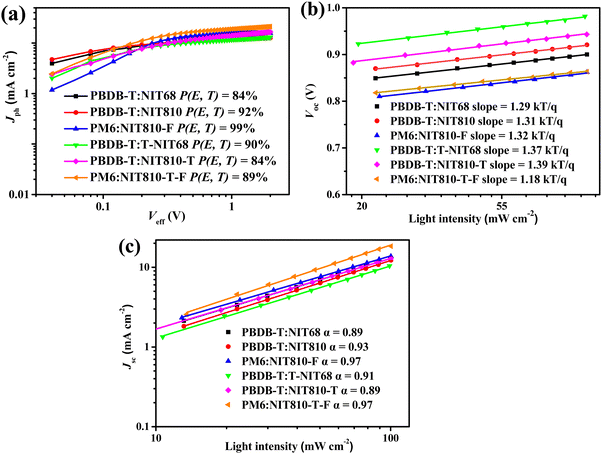 | ||
| Fig. 5 (a) Jphversus Veff, (b) Vocversus light intensity, and (c) Jscversus light intensity of the best OSCs based on six SMAs. | ||
Then, we investigated the possible charge recombination mechanism of these optimized OSC devices by measuring the dependence of Voc on light intensity (Plight). In BHJ OSCs, the fitting straight line of Voc and Plight could be plotted according to Voc ∝ lnPlight with a slope of kT q−1, where q is the elementary charge, k is the Boltzmann constant, and T is the Kelvin temperature.52 From Fig. 5(b), the slopes for all six optimized OSC devices are 1.18–1.39 kT q−1. All of these are closer to 1, indicating that bimolecular recombination mainly exists in these devices. To further investigate the extent of bimolecular recombination in these devices, we next inspect the dependence of Jsc and Plight. The relationship between Jsc and Plight could be described as Jsc ∝ (Plight)α, in which the exponent α infers the degree of bimolecular recombination. When the α value equals 1, it means that all free charge carriers are collected before recombination; while α is less than 1, implying there is a certain degree of bimolecular recombination.52,53 As shown in Fig. 5(c), the calculated α values of PBDB-T:NIT810-, PM6:NIT810-F-, and PM6:NIT810-T-F-based devices are 0.93, 0.97, and 0.97, respectively, which means that bimolecular recombination is more effectively inhibited and relatively efficient charge-carrier transportation in these three devices compared with the other three devices. In general, charge recombination is closely related with the FF and/or Jsc of the OSCs (Table 3). This result should be one of important reasons for the relatively high FF and/or Jsc values in these three OSCs. The other three optimized devices show relatively low α values, around 0.90, indicating that there is relatively serious bimolecular recombination. This should be detrimental to FF and/or Jsc, as disclosed by their photovoltaic properties.
3.6 Morphology and compatibility study
To investigate the effect of the surface morphology of active layers on photovoltaic properties, we performed atomic force microscopy (AFM) with a top model, as displayed in Fig. 6. From the AFM height image (Fig. 6(a)), one can find that the PBDB-T:NIT68 blend film has a moderate root-mean-square (RMS) roughness of 1.70 nm. The increased RMS of 2.29 and 1.73 nm can be found for the PBDB-T:NIT810 and PM6:NIT810-F blend films, respectively (see Fig. 6(b) and (c)). Obvious nanofiber morphological characteristics can be found, indicating more suitable phase separation between polymer donors and SMAs (Fig. 6(h) and (i)). The observed RMS values for the PBDB-T:T-NIT68 and PBDB-T:NIT810-T blends are further increased up to 2.82 and 2.77 nm (see Fig. 6(d) and (e)), meaning there is relatively serious phase separation in these two blends (Fig. 6(j) and (k)). This would be unfavorable to charge transport, thus leading to reduced FFs. Among these six selected blend films, the PM6:NIT810-T-F blend film shows the smallest RMS of 1.07 nm (see Fig. 6(f)), implying the formation of a very suitable phase separation. The different phase-separated properties of these blend films were further explored by transmission electron microscopy (TEM). From Fig. 6(m), (o), and (r), it can be seen that the PBDB-T:NIT68, PM6:NIT810-F, and PM6:NIT810-T-F-based blend films exhibit more uniform species distributions relative to the other three blend films, which is consistent with their smaller RMS values and smoother surface in the AFM images. Furthermore, these three blend films feature bi-continuous interpenetrating network structures, which is conducive to the effective exciton dissociation and charge transport, thus contributing to higher Jsc and/or FF (see Table 3). This suggests that there is good compatibility between the donor and acceptor in these blends, which can also be proven by the following contact angle experiment.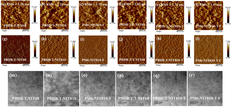 | ||
| Fig. 6 Height (a)–(f) and phase (g)–(l) images of AFM for SMA-based blends prepared under the optimized conditions; TEM images (m)–(r) of six blend films. | ||
The roughness of the surface morphology of the active layer blend film is related to the compatibility between the polymer donor and SMA, which can be validated by measuring the contact angles. Fig. S7 (ESI†) depicts contact angle images and data of water (θwater) and ethylene glycol (EG, θEG) on the pure film of polymer donors (PBDB-T and PM6). The corresponding data are listed in Table S8 in the ESI.† From Fig. S7 (ESI†), two polymer films give a similar θwater of about 99°, but different θEG values of 75.75° and 70.19° for PM6 and PBDB-T, respectively. For the six SMAs, both θwater and θEG have great differences, but the change trends of θwater and θEG for the different small molecules are consistent, as shown in Fig. 7. From the contact angle data (Fig. 7 and Fig. S7, ESI†), the surface energy (γ) can be obtained on the basis of the Owens model54 (see Table S8, ESI†). Next, the compatibility and interaction between the donor and acceptor are evaluated by Flory–Huggins interaction parameter χdonor–acceptor in terms of empirical expression χdonor–acceptor = k[(γdonor)1/2 − (γacceptor)1/2]2, in which k is a positive constant, and γdonor and γacceptor are the surface energy of the corresponding polymer donor and SMA films, respectively.55 For the PBDB-T series, the χdonor–acceptor values are 0.0002, 0.004, 0.473, and 0.072 for PBDB-T:NIT68, PBDB-T:NIT810, PBDB-T:T-NIT68, and PBDB-T:NIT810-T pairs, respectively, which is consistent with their RMS values (1.70, 2.29, 2.82, and 2.77 nm). The obviously low χdonor–acceptor value of the PBDB-T:NIT68 pair compared with other PBDB-T:SMA pairs indicates NIT68 has much better compatibility with PBDB-T relative to other SMAs. Whereas, the PBDB-T:T-NIT68 pair with a large χdonor–acceptor (0.473 k) suggests worse compatibility between T-NIT68 and PBDB-T. This is also in line with the largest RMS value of the AFM image. On the other hand, for PM6-based pairs, the χdonor–acceptor of the PM6:NIT810-T-F pair (0.041 k) is smaller than that of the PM6:NIT810-F pair (0.058 k), indicating that PM6 and NIT810-T-F have better compatibility than that of NIT810-F. The superior compatibility of the polymer donor and SMA could be beneficial to reducing phase separation, thus resulting in optimal surface morphology and further contributing a large Jsc and/or FF in some cases (see Table 2).46,55,56
 | ||
| Fig. 7 Contact angle images and data of water (θwater) and ethylene glycol (EG, θEG) on the pure film of six NIT-based SMAs. | ||
4. Conclusions
Six N,S-heteroarene (NIT)-based SMAs were designed and synthesized through molecular engineering to conveniently investigate the impact of side chain, backbone extension and end group engineering on molecular structure, optoelectronic and photovoltaic properties. The results reveal that end group engineering has a greater effect on the absorption properties and molecular energy levels than those of the side chain and backbone extension engineering. NIT810-T-F shows a redshifted absorption spectrum and lower bandgap relatively to the other five SMAs. The LUMOs of the backbone extension series (T-NIT68, NIT810-T, and NIT810-T-F) are higher than those of the pentacyclic central core series (NIT68, NIT810, and NIT810-F). Theoretical calculation suggests that molecular engineering (side chain, backbone extension and end group) has a limited effect on the backbone planarity of these NIT-based SMAs. OSCs based on the backbone extension series showed a larger Voc than those of the pentacyclic central core series, due to their higher-lying LUMOs. Using polymer PBDB-T as the donor, OSCs based on NIT810 exhibited the highest PCE of 7.25% among these six SMAs. However, when paired with fluorinated polymer PM6, the fluorinated acceptor NIT810-F and NIT810-T-F-based OSCs delivered clearly improved PCEs of up to 7.78% and 9.51%, respectively, compared with the corresponding PBDB-T-based devices, which is mainly due to the obvious increase in both FF and Jsc. The results of device physics and morphology characterization demonstrate that the increased FF and Jsc could be mainly attributed to higher exciton dissociation and charge transport ability, weaker bimolecular recombination, and better phase separation. Our systematical research work focusing on the effect of molecular engineering on molecular structure, optoelectronic and photovoltaic properties would certainly provide some useful guidance for the molecular design of high-performance SMAs.Author contributions
G. Wang, Y. Zhao, M. Li, and P. Huang synthesized and characterized the materials and performed spectroscopic measurements; X. Tang and X. Zhang performed device evaluations with the support of C. Weng; P. Shen designed experiments, wrote the manuscript and and supervised the research project.Conflicts of interest
There are no conflicts to declare.Acknowledgements
The authors gratefully acknowledge the financial support from the National Natural Science Foundation of China (grant no. 21574111), and the Natural Science Foundation of Hunan Province, China (grant no. 2023JJ30578).References
- Y. Lin, J. Wang, Z.-G. Zhang, H. Bai, Y. Li, D. Zhu and X. Zhan, Adv. Mater., 2015, 27, 1170–1174 CrossRef CAS PubMed.
- J. Yuan, Y. Zhang, L. Zhou, G. Zhang, H.-L. Yip, T.-K. Lau, X. Lu, C. Zhu, H. Peng, P. A. Johnson, M. Leclerc, Y. Cao, J. Ulanski, Y. Li and Y. Zou, Joule, 2019, 3, 1140–1151 CrossRef CAS.
- L. Gao, Z.-G. Zhang, L. Xue, J. Min, J. Zhang, Z. Wei and Y. Li, Adv. Mater., 2016, 28, 1884–1890 CrossRef CAS PubMed.
- L. Kong, Z. Zhang, N. Zhao, Z. Cai, J. Zhang, M. Luo, X. Wang, M. Chen, W. Zhang, L. Zhang, Z. Wei and J. Chen, Adv. Energy Mater., 2023, 13, 2300763 CrossRef CAS.
- B. Pang, C. Liao, X. Xu, L. Yu, R. Li and Q. Peng, Adv. Mater., 2023, 35, 2300631 CrossRef CAS PubMed.
- B. Fan, W. Zhong, W. Gao, H. Fu, F. R. Lin, R. W.-Y. Wong, M. Liu, C. Zhu, C. Wang, H.-L. Yip, F. Liu and A. K.-Y. Jen, Adv. Mater., 2023, 35, 2302861 CrossRef CAS PubMed.
- B. Deng, H. Lian, B. Xue, R. Song, S. Chen, Z. Wang, T. Xu, H. Dong and S. Wang, Small, 2023, 19, 2207505 CrossRef CAS PubMed.
- H. Chen, S. Y. Jeong, J. Tian, Y. Zhang, D. R. Naphade, M. Alsufyani, W. Zhang, S. Griggs, H. Hu, S. Barlow, H. Y. Woo, S. R. Marder, T. D. Anthopoulos, I. McCullochbd and Y. Li, Energy Environ. Sci., 2023, 16, 1062–1070 RSC.
- Z. Zheng, J. Wang, P. Bi, J. Ren, Y. Wang, Y. Yang, X. Liu, S. Zhang and J. Hou, Joule, 2022, 6, 171–184 CrossRef CAS.
- J. Fu, P. W. K. Fong, H. Liu, C.-S. Huang, X. Lu and S. Lu, Nat. Commun., 2023, 14, 1760 CrossRef CAS PubMed.
- J. Gao, N. Yu, Z. Chen, Y. Wei, C. Li, T. Liu, X. Gu, J. Zhang, Z. Wei, Z. Tang, X. Hao, F. Zhang, X. Zhang and H. Huang, Adv. Sci., 2022, 9, 2203606 CrossRef CAS PubMed.
- R. Sun, Y. Wu, X. Yang, Y. Gao, Z. Chen, K. Li, J. Qiao, T. Wang, J. Guo, C. Liu, X. Hao, H. Zhu and J. Min, Adv. Mater., 2022, 34, 2110147 CrossRef CAS PubMed.
- H. Wang, J. Cao, J. Yu, Z. Zhang, R. Geng, L. Yang and W. Tang, J. Mater. Chem. A, 2019, 7, 4313–4333 RSC.
- S. Li, C.-Z. Li, M. Shi and H. Chen, ACS Energy Lett., 2020, 5, 1554–1567 CrossRef CAS.
- Y. Liu, B. Liu, C. Q. Ma, F. Huang, G. Feng, H. Chen, J. Hou, L. Yan, Q. Wei, Q. Luo, Q. Bao, W. Ma, W. Liu, W. Li, X. Wan, X. Hu, Y. Han, Y. Li, Y. Zhou, Y. Zou, Y. Chen, Y. Li, Y. Chen, Z. Tang, Z. Hu, Z.-G. Zhang and Z. Bo, Sci. China: Chem., 2022, 65, 224–268 CrossRef CAS.
- H. Yu, Z. Qi, J. Yu, Y. Xiao, R. Sun, Z. Luo, A. M. H. Cheung, J. Zhang, H. Sun, W. Zhou, S. Chen, X. Guo, X. Lu, F. Gao, J. Min and H. Yan, Adv. Energy Mater., 2020, 10, 2003171 Search PubMed.
- L. Yan, H. Zhang, Q. An, M. Jiang, A. Mahmood, M. H. Jee, H.-R. Bai, H.-F. Zhi, S. Zhang, H. Y. Woo and J.-L. Wang, Angew. Chem., Int. Ed., 2022, 61, e2022094 Search PubMed.
- H. Yao, J. Wang, Y. Xu and J. Hou, Chem. Mater., 2023, 35, 807–821 CrossRef CAS.
- G. Wu, X. Xu, C. Liao, L. Yu, R. Li and Q. Peng, Small, 2023, 19, 2302127 CrossRef CAS PubMed.
- X. Kong, C. Zhu, J. Zhang, L. Meng, S. Qin, J. Zhang, J. Li, Z. Wei and Y. Li, Energy Environ. Sci., 2022, 15, 2011–2020 RSC.
- J. Cao, H. Wang, S. Qu, J. Yu, L. Yang, Z. Zhang, F. Du and W. Tang, Adv. Funct. Mater., 2020, 30, 2006141 CrossRef CAS.
- J. Liang, P. Yin, T. Zheng, G. Wang, X. Zeng, C. Cui and P. Shen, J. Mater. Chem. C, 2019, 7, 10028–10038 RSC.
- X. Tang, H. Liao, T. Zheng, P. Yin, J. Cao, X. Zeng, C. Weng and P. Shen, Chem. – Eur. J., 2021, 27, 14508–14519 CrossRef CAS PubMed.
- C. Bulumulla, R. Gunawardhana, P. L. Gamage, J. T. Miller, R. N. Kularatne, M. C. Biewer and M. C. Stefan, ACS Appl. Mater. Interfaces, 2020, 12, 32209–32232 CrossRef CAS PubMed.
- B. Lu, Z. Chen, B. Jia, J. Wang, W. Ma, J. Lian, P. Zeng, J. Qu and X. Zhan, ACS Appl. Mater. Interfaces, 2020, 12, 14029–14036 CrossRef CAS PubMed.
- T.-W. Chen, K.-L. Peng, Y.-W. Lin, Y.-J. Su, K.-J. Ma, L. Hong, C.-C. Chang, J. Hou and C.-S. Hsu, J. Mater. Chem. A, 2020, 8, 1131–1137 RSC.
- H. Feng, X. Song, M. Zhang, J. Yu, Z. Zhang, R. Geng, L. Yang, F. Liu, D. Baran and W. Tang, Mater. Chem. Front., 2019, 3, 702–708 RSC.
- R. Geng, X. Song, H. Feng, J. Yu, M. Zhang, N. Gasparini, Z. Zhang, F. Liu, D. Baran and W. Tang, ACS Energy Lett., 2019, 4, 763–770 CrossRef CAS.
- J. Sun, X. Ma, Z. Zhang, J. Yu, J. Zhou, X. Yin, L. Yang, R. Geng, R. Zhu, F. Zhang and W. Tang, Adv. Mater., 2018, 30, 1707150 CrossRef PubMed.
- X. Ma, W. Gao, J. Yu, Q. An, M. Zhang, Z. Hu, J. Wang, W. Tang, C. Yang and F. Zhang, Energy Environ. Sci., 2018, 11, 2134–2141 RSC.
- M. Chen, Z. Zhang, W. Li, J. Cai, J. Yu, E. L. K. Spooner, R. C. Kilbride, D. Li, B. Du, R. S. Gurney, D. Liu, W. Tang, D. G. Lidzey and T. Wang, Sci. China: Chem., 2019, 62, 1221–1229 CrossRef CAS.
- G. Li, D. Li, R. Ma, T. Liu, Z. Luo, G. Cui, L. Tong, M. Zhang, Z. Wang, F. Liu, L. Xu, H. Yan and B. Tang, J. Mater. Chem. A, 2020, 8, 5927–5935 RSC.
- G. Li, C. Xu, Z. Luo, W. Ning, X. Liu, S. Gong, Y. Zou, F. Zhang and C. Yang, ACS Appl. Mater. Interfaces, 2020, 12, 13068–13076 CrossRef CAS PubMed.
- Y. Ma, D. Cai, S. Wan, P. Wang, J. Wang and Q. Zheng, Angew. Chem., Int. Ed., 2020, 59, 21627–21633 CrossRef CAS PubMed.
- X. Chen, H. Liu, L. Xia, T. Hayat, A. Alsaedic and Z. Tan, Chem. Commun., 2019, 55, 7057–7060 RSC.
- Y. Zhang, Y. Ji, Y. Zhang, W. Zhang, H. Bai, M. Du, H. Wu, Q. Guo and E. Zhou, Adv. Funct. Mater., 2022, 32, 2205115 CrossRef CAS.
- W. Liu, S. Sun, L. Zhou, Y. Cui, W. Zhang, J. Hou, F. Liu, S. Xu and X. Zhu, Angew. Chem., Int. Ed., 2022, 61, e202116111 CrossRef CAS PubMed.
- L. Xie, Y. Zhang, W. Zhuang, S. Y. Jeong, Q. Bian, H. Li, J. Cao, W. Liu, H. Tan, H. Y. Woo, J. Zhang and E. Wang, Chem. Eng. J., 2022, 427, 131674 CrossRef CAS.
- J. Chen, J. Cao, L. Liu, L. Xie, H. Zhou, J. Zhang, K. Zhang, M. Xiao and F. Huang, Adv. Funct. Mater., 2022, 32, 2200629 CrossRef CAS.
- J. Lee, S.-J. Ko, M. Seifrid, H. Lee, C. McDowell, B. R. Luginbuhl, A. Karki, K. Cho, T.-Q. Nguyen and G. C. Bazan, Adv. Energy Mater., 2018, 8, 1801209 CrossRef.
- G. Li, X. Zhang, L. O. Jones, J. M. Alzola, S. Mukherjee, L.-W. Feng, W. Zhu, C. L. Stern, W. Huang, J. Yu, V. K. Sangwan, D. M. DeLongchamp, K. L. Kohlstedt, M. R. Wasielewski, M. C. Hersam, G. C. Schatz, A. Facchetti and T. J. Markss, J. Am. Chem. Soc., 2021, 143, 6123–6139 CrossRef CAS PubMed.
- S. M. Swick, W. G. Zhu, M. Matta, T. J. Aldrich, A. Harbuzaru, J. T. L. Navarrete, R. P. Ortiz, K. L. Kohlstedt, G. C. Schatz, A. Facchetti, F. S. Melkonyan and T. J. Marks, Proc. Natl. Acad. Sci. U. S. A., 2018, 115, E8341–E8348 CrossRef CAS PubMed.
- X. Li, T. Yan, H. Bin, G. Han, L. Xue, F. Liu, Y. Yi, Z.-G. Zhang, T. P. Russell and Y. Li, J. Mater. Chem. A, 2017, 5, 22588–22597 RSC.
- Y. Li, X. Liu, F. Wu, Y. Zhou, Z. Jiang, B. Song, Y. Xia, Z.-G. Zhang, F. Gao, O. Inganäs, Y. Li and L. Liao, J. Mater. Chem. A, 2016, 4, 5890–5897 RSC.
- Q. Guo, R. Ma, J. Hu, Z. Wang, H. Sun, X. Dong, Z. Luo, T. Liu, X. Guo, X. Guo, H. Yan, F. Liu and M. Zhang, Adv. Funct. Mater., 2020, 30, 2000383 CrossRef CAS.
- Z. Luo, R. Ma, Y. Xiao, T. Liu, H. Sun, M. Su, Q. Guo, G. Li, W. Gao, Y. Chen, Y. Zou, X. Guo, M. Zhang, X. Lu, H. Yan and C. Yang, Small, 2020, 16, 2001942 CrossRef CAS PubMed.
- X. Shi, L. Zuo, S. B. Jo, K. Gao, F. Lin, F. Liu and A. K.-Y. Jen, Chem. Mater., 2017, 29, 8369–8376 CrossRef CAS.
- Y. Liu, C. Zhang, D. Hao, Z. Zhang, L. Wu, M. Li, S. Feng, X. Xu, F. Liu, X. Chen and Z. Bo, Chem. Mater., 2018, 30, 4307–4312 CrossRef CAS.
- M. Li, M. Zeng, X. Tang, T. Zheng, C. Weng and P. Shen, ACS Appl. Energy Mater., 2021, 4, 8117–8129 CrossRef CAS.
- T. Zheng, X. Tang, P. Yin, L. Chen, J. Liang, C. Weng and P. Shen, J. Mater. Chem. C, 2021, 9, 3295–3306 RSC.
- K. He, P. Kumar, Y. Yuan and Y. Li, Mater. Adv., 2021, 2, 115–145 RSC.
- L. J. A. Koster, V. D. Mihailetchi, R. Ramaker and P. W. M. Blom, Appl. Phys. Lett., 2005, 86, 123509 CrossRef.
- A. K. K. Kyaw, D. H. Wang, V. Gupta, W. L. Leong, L. Ke, G. C. Bazan and A. J. Heeger, ACS Nano, 2013, 7, 4569–4577 CrossRef CAS PubMed.
- D. K. Owens and R. C. Wendt, J. Appl. Polym. Sci., 1969, 13, 1741–1747 CrossRef CAS.
- Z. Zhang, H. Wang, J. Yu, R. Sun, J. Xu, L. Yang, R. Geng, J. Cao, F. Du, J. Min, F. Liu and W. Tang, Chem. Mater., 2020, 32, 1297–1307 CrossRef CAS.
- X. Wang, J. Han, H. Jiang, Z. Liu, Y. Li, C. Yang, D. Yu, X. Bao and R. Yang, ACS Appl. Mater. Interfaces, 2019, 11, 44501–44512 CrossRef CAS PubMed.
Footnote |
| † Electronic supplementary information (ESI) available. See DOI: https://doi.org/10.1039/d3tc03309k |
| This journal is © The Royal Society of Chemistry 2024 |

