
 Open Access Article
 This Open Access Article is licensed under a Creative Commons Attribution-Non Commercial 3.0 Unported Licence
Understanding pore size relation in cellulose-derived, nitrogen-doped, hydrothermal carbons for improved supercapacitor performance†
Manuel
Prieto
 ab,
Gary J.
Ellis
a,
Vitaliy
Budarin
a,
Enrique
Morales
a,
Mohammed
Naffakh
b and
Peter S.
Shuttleworth
*a
ab,
Gary J.
Ellis
a,
Vitaliy
Budarin
a,
Enrique
Morales
a,
Mohammed
Naffakh
b and
Peter S.
Shuttleworth
*a
aDepartamento de Física de Polímeros, Elastómeros y Aplicaciones Energéticas, Instituto de Ciencia y Tecnología de Polímeros, Consejo Superior de Investigaciones Científicas, C/Juan de la Cierva, 3, 28006 Madrid, Spain. E-mail: peter@ictp.csic.es
bDepartamento de Física e Ingeniería de Materiales, Escuela Técnica Superior de Ingenieros Industriales, Universidad Politécnica de Madrid (ETSII-UPM), C/ José Gutiérrez Abascal, 2, 28006, Madrid, Spain
First published on 25th September 2024
Abstract
This study introduces an eco-friendly approach for synthesising cellulose-derived activated carbons, using hydrothermal carbonisation (HTC) followed by high-temperature pyrolysis. This novel method proves more carbon-efficient than the traditional carbonisation and activation processes. Moreover, we incorporate albumin as a sustainable nitrogen source in the preparation phase, with a view to enhancing the properties of the resulting carbons. We examine the morphological and textural characteristics of the carbons produced using scanning electron microscopy (SEM) and nitrogen sorption analysis. The chemical structure of the activated carbons was characterised using elemental microanalysis, Energy-Dispersive X-ray Spectroscopy (EDX), and X-ray Photoelectron Spectroscopy (XPS). The electrochemical evaluation was conducted in a symmetrical Swagelok cell, with a 2 M H2SO4 aqueous solution electrolyte. The carbons obtained exhibited remarkable electrochemical performance, achieving capacitance values exceeding 275 F g−1 and power densities approaching 3000 W kg−1. Crucially, we discovered a significant correlation between enhanced material capacitance and the presence of pores of around 4.3 Å, the approximate diameter of the sulfate ion (SO42−). This work highlights the significance of specific pore size in the electrochemical behaviour of the electrodes, advancing our understanding of the relationship between material structure and performance, and provides insight for the further development of sustainable high-performance materials for energy storage applications.
1. Introduction
The urgent need for a sustainable energy grid to meet the escalating energy demand (driven by factors such as the increasing population1 and demand,2,3 ever-growing cost of fuels,4 and environmental issues) has encouraged extensive research and development of energy storage technologies.5 Electrochemical energy storage is one of the most promising approaches, and this study aims to develop upon it.Two main storage devices in this category stand out: batteries and electrochemical capacitors, or supercapacitors (SCs). When comparing both technologies, SCs excel in having greater power densities, as well as more excellent durability and efficiency. The energy storage mechanism in batteries is based on the transformation of chemical energy into electrical energy through redox processes that take place in the anode and cathode.6 Meanwhile, SC energy storage occurs through two mechanisms. The first one is electrical double-layer capacitance (EDLC), a purely electrostatic process that occurs through a surface polarisation of the electrode at the interface between the electrode and electrolyte.7,8 The second mechanism is pseudocapacitance, in which energy is stored during reduction–oxidation reactions. This is similar to battery energy storage, in which electrolyte ions move to the electrode with the opposite charge when voltage is applied.7
A typical symmetrical supercapacitor comprises two electrodes, an electrolyte, a separator, two current collectors, and a cell to contain the rest of the elements. The key parts in an SC are both the electrode and electrolyte. The electrolyte, which is mainly liquid, supplies ions for surface polarisation. There are three main types of electrolytes: aqueous, ionic liquids, and organic.9 All electrolytes must meet some requirements, such as high conductivity, low toxicity, low viscosity and high chemical and thermal stability.10
The electrodes provide the surface for the ion deposition that leads to polarisation. Pseudocapacitors' electrodes are generally made of transition metal oxides,11,12 and conductive polymers.13 Nitrogen-containing compounds have also been employed, given the importance of heteroatom content for redox processes.14,15 One promising nitrogen precursor is albumin, which could be a source of nitrogen-doped carbon dots.16 Typical EDLC electrodes are made of carbon-containing materials. Recently, additives in the form of graphene17–19 and carbon nanotubes20–22 have been widely used to improve the efficiency of electrodes. However, given the high cost of these materials, a growing interest in activated carbon (AC) for use as electrodes in both EDLC and pseudocapacitors is emerging.23–25
The application of ACs presents an especially promising alternative, harnessing the potential of widely available biomass feedstocks. With an estimated 13 × 109 hectares of available land on our planet, of which only 37% is used for agriculture, biomass is a sustainable and abundant resource.26 Of the approximately 170 gigatonnes of lignocellulosic biomass produced, only 5% is used for food and non-food competitive purposes.27 This highlights the vast potential of sustainably-sourced non-food-competitive biomass and biowaste, which can be found on most continents and offer a cost-effective, efficient, and renewable precursor for ACs. In particular, cellulose is a promising candidate for carbonaceous materials due to it being highly abundant and non-food competitive.28
In a substantial number of cases, biomass contains notable amounts of moisture (both due to its nature and precipitations),29 which creates an additional problem associated to the extra energy needed to evaporate it. Furthermore, pyrolysis is accompanied by emissions of greenhouse gases (GHGs) and dangerous volatile substances. This problem can be solved by using hydrothermal carbonisation (HTC), a less energy-consuming method that eliminates the pre-drying stage,30,31 reduces the formation of harmful chemicals32 and facilitates high carbon content materials to be obtained.33
The primary purpose of this study is to describe the hydrothermal production and characterisation of activated carbons obtained from biomass and their use as electrodes for supercapacitors. A fundamental aim is to examine the impact of introducing albumin, a natural nitrogen-rich substance, on changes to the activated carbon pore structure, and to evaluate how these structural modifications affect the electrochemical efficiency of the resulting electrodes.
2. Experimental section
2.1 Synthesis of activated carbon
All reagents and chemicals (microcrystalline cellulose, egg albumin, potassium hydroxide, hydrochloric acid) were purchased from Sigma-Aldrich and used as supplied.2.2 Preparation of nitrogen-doped carbons
Cellulose: albumin mixtures with a 4![[thin space (1/6-em)]](https://www.rsc.org/images/entities/char_2009.gif) :1 mass ratio (12 g) were dispersed in 36 mL of water and then charged into a 140 mL autoclave and left at 200 °C for 5 hours. The resulting solution was filtered and the residual solid dried, and then heated at 300 °C for 5 hours. It was later mixed with KOH in different mass ratios to alter the porosity of the prepared electrodes. In the last step, the samples were heated at 800 °C to obtain the final AC product, and then cleaned repeatedly with 5% HCl and water until a neutral pH was achieved. This was to ensure complete removal of any potassium residues within the carbons, as verified by EDX and TGA analyses (see Fig. S1†). For comparison, non-albumin doped carbons were prepared following the same methodology but starting with an aqueous cellulose solution (12 g of cellulose in 36 mL of water). The carbon electrodes were named CA 1–, with A standing for albumin (when present) and x for the cellulose to KOH ratio.
:1 mass ratio (12 g) were dispersed in 36 mL of water and then charged into a 140 mL autoclave and left at 200 °C for 5 hours. The resulting solution was filtered and the residual solid dried, and then heated at 300 °C for 5 hours. It was later mixed with KOH in different mass ratios to alter the porosity of the prepared electrodes. In the last step, the samples were heated at 800 °C to obtain the final AC product, and then cleaned repeatedly with 5% HCl and water until a neutral pH was achieved. This was to ensure complete removal of any potassium residues within the carbons, as verified by EDX and TGA analyses (see Fig. S1†). For comparison, non-albumin doped carbons were prepared following the same methodology but starting with an aqueous cellulose solution (12 g of cellulose in 36 mL of water). The carbon electrodes were named CA 1–, with A standing for albumin (when present) and x for the cellulose to KOH ratio.
2.3 Characterization of the samples
Microanalysis tests were carried out in a Leco Analyzer CHNS 932. SEM micrographs and EDX measurements were obtained in an ultra-high field emission scanning microscope (Hitachi SU8030). XPS analyses were conducted using Thermo Electron's ESCALAB 250 instrument. The excitation source was the monochromatic Al Kα line (1486.6 eV). The photoelectron spectra were calibrated regarding binding energy to the energy of the C–Si (SiC) component at 282.5 eV. The charge is compensated by a low-energy electron beam (−2 eV). FTIR spectra were acquired using PerkinElmer 2000 equipment with 100 scans per sample over the wavenumber range of 4000 to 400 cm−1, at a resolution of 4 cm−1.Textural properties were analysed by N2 (77 K; p/p0: 10−6–0.995) sorption, weighing approximately 100 mg of sample and testing in a Micromeritics 3Flex Analyzer after degasification at 200 °C for 12 hours. Specific surface area was calculated following the Brunauer–Emmett–Teller (BET) method in the pressure range of 10−6–0.1, with R2 > 0.999. Micropore surface and volume were calculated using t-plot methodology with at least 10–15 points. The Horvath–Kawazoe method was also applied to further analyse the micropores. NLDFT method was used to evaluate the pore size distribution of the mesoporous materials.
For electrical and electrochemical measurements, symmetrical two-electrode supercapacitor cells were assembled in Swagelok™ cells, using a Whatman 934AH glassy fibre paper separator and two A20 alloy stainless steel rods as current collectors. Electrodes were obtained by pressing the carbon powder into pills (60% active material, 30% PTFE binder, 10% C65 graphite), and a 2 M H2SO4 aqueous solution was used as an electrolyte.
Conductivity measurements, cyclic voltammetry (1–100 mV s−1) and galvanostatic charge/discharge (CDC) tests (1–190 mA) were conducted using a Solartron 1480 multichannel potentiostat/galvanostat. Impedance spectroscopy analyses were performed with a Solatron 1255B frequency response analyser in the 106–10−1 Hz range with an alternate current perturbation of 10 mV.
3. Results and discussion
3.1 Characterization of the carbonaceous structures
Elemental microanalyses (shown in Table 1), as well as Energy Dispersive X-ray spectroscopy (EDX) and X-ray photoelectron Spectroscopy (XPS) tests, show the same trends for all the developed samples. The results reveal a successful hydrothermal carbonisation (HTC) process in cellulose and cellulose/albumin mixtures, increasing carbon content from 42% in pristine cellulose to 62% after HTC and subsequent carbonisation at 300 °C. This data is especially interesting when compared with cellulose directly carbonised at 300 °C without a hydrothermal step, which has a % C of only 44%, highlighting the importance of the hydrothermal process. These results are backed by FTIR analyses (see Fig. S2†), where bands at 1730 and 1530 cm−1 can be observed in hydrochars, not present in cellulose. The first band confirms the presence of carboxylic groups as a result of oxidation of carbons during HTC, and the second one suggests the presence of aromatic C![[double bond, length as m-dash]](https://www.rsc.org/images/entities/char_e001.gif) C bonds,34 implying the beginning of conjugation and aromatisation processes in the material. Final carbons after activation, with an average % C of 80%, represent a 100% increase in carbon content concerning the original precursor(s).
C bonds,34 implying the beginning of conjugation and aromatisation processes in the material. Final carbons after activation, with an average % C of 80%, represent a 100% increase in carbon content concerning the original precursor(s).
| Sample | % C | % H | % N | % O |
|---|---|---|---|---|
| C300 | 61.7 | 4.8 | 0.1 | 33.4 |
| C 1–1.5 | 83.7 | 1.2 | 0.1 | 15.0 |
| CA 1–1.5 | 83.0 | 1.4 | 1.1 | 14.4 |
| C 1–4 | 82.7 | 1.0 | 0.2 | 16.1 |
| CA 1–4 | 80.8 | 1.3 | 1.2 | 16.5 |
All ACs obtained at different conditions have very similar elemental compositions. For example, the variation of carbon content in these samples is less than 3%. The protein addition demonstrates the five times increase in % N for the albumin-free to albumin-loaded samples (from 0.2 to 1.2%).
The results of elemental microanalysis and their trends are supported on an atomic and mass scale by EDX (see Table S1†) and XPS tests, confirming a successful blend of polysaccharides and proteins inside the cellulose-based carbon.
Due to the negligible difference between the elemental analysis of samples prepared with 1–1.5 and 1–4 KOH ratios, only one sample (CA 1–4) was tested for XPS. In contrast to the sample preparation before elemental analysis, a thorough drying process was performed before the XPS measurements. All XPS data agree with the values obtained by elemental microanalysis, highlighting the presence of nitrogen in the samples doped with albumin at levels close to 1%.
Fig. 1 shows the deconvolution of the XPS peak of the N 1s atom in the CA 1–4 sample, in which the contribution of different nitrogen-containing functional groups (pyridinic, pyrrolic, graphitic35,36) are demonstrated. As Table 2 shows, pyrrolic and graphitic nitrogen are the most prevalent. Furthermore, to fully comprehend the electrochemical performance of these carbons, it is paramount to understand the porous structure of the developed materials first. For this purpose, porosimetry analyses were carried out using nitrogen sorption testing.
 | ||
| Fig. 1 XPS deconvolution of the N 1s spectrum of the CA 1–4 sample. | ||
| Group | Peak (eV) | Area (%) |
|---|---|---|
| Pyridinic | 399.0 | 14.5 |
| Pyrrolic | 400.6 | 46.9 |
| Graphitic | 401.6 | 38.6 |
Nitrogen adsorption isotherms shown in Fig. 2 reveal that all samples display Type I (b) isotherms except C 1–1.5, which corresponds to microporous materials with small, narrow mesopores with a pore size no larger than 2.5 nm.37
 | ||
| Fig. 2 Nitrogen adsorption isotherms of activated carbon samples prepared at, (A) a 1–1.5 cellulose to KOH ratio, and (B) a 1–4 ratio. | ||
The C 1–1.5 sample displays an IV-type isotherm, representing mesoporous carbons with a pore width exceeding a threshold of 2 nm, separating micro and mesopore. Concretely, this hysteresis loop corresponds to a type H2 (b), which usually correlates to a narrow distribution of pores with wide neck sizes.38 Therefore, it is assumed that this carbon contains a network of cavities (>30 nm) connected by bottle-shaped pores with a width more significant than the critical pore width aperture.
Key surface area and pore volume data obtained from the isotherms shown in Fig. 2 are provided in Table 3. It is observed that the micropore volume of the prepared ACs increases with increasing KOH to cellulose ratios, irrespective of the presence or absence of albumin (N-enriched samples). However, the incorporation of albumin does have some effect. For example, comparing the samples CA 1–1.5 and C 1–1.5, the increase in pore size is approximately 30%. However, when the proportion of alkali in the activation mixture rises to 80%, the influence of nitrogen doping reduces this significantly, showing an increase of not more than 10%. To explain this difference in the textural properties of conventional and N-doped samples, it can be assumed that including nitrogen atoms significantly increases the number of active centres on the carbon surface. Their presence could stimulate the formation of micropores and inhibit their development into mesopores, as will be discussed later. Only one sample (C 1–1.5) demonstrates developed mesoporosity, with a mesopore volume of around 0.42 cm3 g−1. The remaining samples are considerably microporous, with a level of microporosity >90%.
| Sample | S BET (m2 g−1) | TPVb (cm3 g−1) | S micro (m2 g−1) | V micro (cm3 g−1) | Level of microporosity (%) |
|---|---|---|---|---|---|
| a Surface area is calculated using the BET method. b Total pore volume calculated at a relative pressure of P/P0 >0.99. c Micropore surface and volume calculated by the t-plot methodology (>10 points). | |||||
| C 1–1.5 | 1215 | 0.875 | 1167 | 0.456 | 52 |
| CA 1–1.5 | 1589 | 0.658 | 1540 | 0.611 | 93 |
| C 1–4 | 1674 | 0.678 | 1636 | 0.647 | 95 |
| CA 1–4 | 1759 | 0.757 | 1701 | 0.702 | 93 |
To further understand the mechanism of KOH biomass activation, it was decided to analyse in detail the dependence of the micropore structure of the samples obtained under various conditions. The pore distribution of the samples in the micropore region acquired via the Horvath–Kawazoe method was deconvoluted and analysed in detail, as shown in Fig. 3.
 | ||
| Fig. 3 A detailed comparative assessment of the Horvath–Kavazoe pore distribution in ACs obtained from both neat cellulose and nitrogen-enriched cellulose, activated with different initial cellulose-to-KOH ratios: (A) this panel presents a direct comparative profile of the pore distributions in the various AC samples. (B) Lorentzian deconvolution of the microporous pore distributions of samples derived from neat cellulose. (C) The panel outlines the bifurcation of microporosity in N-related AC samples into two distinct pore categories resulting from the KOH interaction with distinct active centres on the surface: (i) active centres contain only carbon atoms and (ii) active centres containing both nitrogen and carbon atoms. | ||
Pore formation within these types of activated carbons can be considered as a random process, which could be explained by the main statistical distribution models such as Gaussian and Lorentzian. For example, Gaussian fitting works well for homogeneous pore size distributions of uniform and well-defined pores, while Lorentzian deconvolution is more appropriate for interconnected, and/or irregular pores, typical of porous carbons.39–41
The results show that for both cellulose-to-KOH ratios, the changes in pore distribution due to the influence of sample nitrogen doping display similar features. In the presence of albumin, the prominent low-width peak at around 0.38 nm is decreased while the width of the wider pore (>0.5 nm) increases.
It was found that the Lorentzian deconvolution approach is the most effective compared to other mathematical methods of micropore peak separating. It accurately characterises pore size distributions of the ACs samples derived directly from neat cellulose with over 99% accuracy, applying only three peaks, as depicted in Fig. 3B. The first two peaks, consistent across both cellulose-to-KOH ratios, have approximate positions set at 0.375 nm and 0.445 nm, referenced C-related peaks (C-RP) 1 and 2 (Fig. 3A and B). The third wider-distribution peak (with half-width ≈0.5 nm) for the samples shows average pore width of 0.76 nm and 0.6 nm for C 1–1.5 and C 1–4, respectively. This peak could result from different interactions, the nature of which is complex to determine, and is yet to be classified.
Analysis of the nitrogen-doped samples, as detailed in Table 4 and in the ESI Fig. S3,† has yielded some interesting findings. These samples show two distinct peaks that are nearly identical in position to those found in the non-doped samples as indicated by a red line in Fig. 3C. These peaks in the nitrogen-doped samples diverge from those produced from neat cellulose only by less than 0.01 nm and have been designated as C-RP1 and C-RP2. Notably, two additional peaks appear in the nitrogen-doped activated carbon samples, termed N-related Peaks (N-RP1 and N-RP2). These are marked with a blue line in Fig. 3C and are visibly distinct from the red line peaks (C-RP1 & C-RP-2), shifting to the right compared to them. This pore width shifts ranges from 0.02 nm to 0.09 nm, varying with the concentration of KOH in the initial mix. The total micropore volume of nitrogen-doped samples is approximately 1.2 times greater than the un-doped samples (Fig. 3C and Table 4).
| Pore attribution | Pore characteristicsa | |||||||
|---|---|---|---|---|---|---|---|---|
| Cellulose: KOH ratio | ||||||||
| 1:1.5 |
1:4 |
|||||||
| Pore width (nm) | Pore volume (cm3 g−1) | Pore width (nm) | Pore volume (cm3 g−1) | |||||
| C 1–1.5 | CA 1–1.5 | C 1-1.5 | CA 1–1.5 | C 1–4 | CA 1–4 | C 1–4 | CA 1–4 | |
| a The Horvath–Kawazoe pore distribution was deconvoluted to the individual peaks using Lorentzian deconvolution. b C-RP(x) = carbon-related pore. (x)-pore type number. C-RPs are produced due to the interaction of KOH with the biochar surface carbon atoms. c N-RP(x) = Nitrogen-related pore. (x)-pore type number. N-RPs are produced due to the interaction of KOH and nitrogen-containing active centres on the biochar surface. d Un-P = Unassigned pore. The pore type number is 5. | ||||||||
| C-RP1b | 0.38 | 0.38 | 0.17 | 0.11 | 0.37 | 0.36 | 0.09 | 0.03 |
| C-RP2 | 0.46 | 0.47 | 0.22 | 0.12 | 0.43 | 0.43 | 0.36 | 0.13 |
| N-RP1c | 0.0 | 0.42 | 0.00 | 0.12 | 0.00 | 0.39 | 0.0 | 0.07 |
| N-RP2 | 0.0 | 0.55 | 0.00 | 0.07 | 0.00 | 0.49 | 0.0 | 0.24 |
| Un-Pd | 0.76 | 0.75 | 0.08 | 0.14 | 0.60 | 0.75 | 0.18 | 0.25 |
| Total C-DP pores volume | 0.39 | 0.23 | 0.45 | 0.16 | ||||
| Total N-DP pores volume | 0.00 | 0.19 | 0.00 | 0.31 | ||||
| Total micropores volume | 0.47 | 0.57 | 0.64 | 0.74 | ||||
It could be proposed that N-related peaks appeared due to the activation of nitrogen-doped clusters, which enhance atom removal during KOH treatment. The electron-withdrawing nature of these nitrogen atoms imparts an electrophilic character to the neighbouring carbon atoms. This facilitates nucleophilic attack by the hydroxide ions from KOH. Evidence from XPS indicates the presence of imine groups in N-doped carbons (see Fig. 1 and Table 2). KOH could promote imine hydrolysis into aldehydes or ketones and release ammonia or amine, contributing to carbon surface pore formation. This process may promote the removal of more atoms from the N-doped clusters than from the non-doped ones due to the simultaneous withdrawal of both nitrogen and carbon.
SEM images displayed in Fig. 4 demonstrate a successful generation of porosity in the biomass-derived carbons. Pristine cellulose and hydrochar micrographs have not been displayed as these samples don't exhibit any porosity. However, activated cellulose shows a combination of meso- and macropores. The structure of this porous network varies with the amount of KOH used, with more predominant macropores in the higher KOH-dosed samples. Furthermore, it is interesting that the C 1–1.5 sample displays a continuous external structure with few macropores, contrasting with a significant mesopore presence, unlike the rest of the samples, which is in agreement with porosimetry data (see Fig. 2).
 | ||
| Fig. 4 SEM images of (A) C 1–1.5, (B) C 1–4, (C) CA 1–1.5 and (D) CA 1–4. | ||
3.2 Electrical and electrochemical results
The electrical conductivity results in Table 5 demonstrate a considerable difference depending on the KOH dosage. In general, the samples prepared using a 1–1.5 cellulose-to-KOH ratio show a conductivity approximately twice that of those prepared using a 1–4 ratio. This could be related to the slightly higher carbon content and lower oxygen content of the 1–1.5 ratio samples. On another note, the addition of albumin does not show a significant trend, increasing conductivity by 11% in C 1–1.5 but decreasing it by 17% in C 1–4.| Sample | C 1–1.5 | CA 1–1.5 | C 1–4 | CA 1–4 |
|---|---|---|---|---|
| Conductivity (S m−1) | 10.46 | 11.74 | 5.69 | 4.68 |
Cyclic voltammograms (1–100 mV s−1) displayed in Fig. 5A show a quasi-rectangular shaped profile, typical of a purely electrostatic process without any pseudocapacitive contribution. As the scan rate increases, this form changes gradually towards elliptical shaped, due to restrictions of ion diffusion and the electrode polarization processes, which in turn leads to losses in energy efficiency. This result also agrees with the observed decrease in calculated specific capacitance values with increasing scan rate (Fig. 5B), with a loss of up to 80% of the initial specific capacitance when changing from 1 to 100 mV s−1. Table 6 shows the specific capacitance (calculated at 1 mA) from constant current galvanostatic charge/discharge tests. Remarkably, C 1–4, the more microporous sample without albumin, displays an excellent capacitance of 275 F g−1 due to its combination of high surface area and higher micropore to total pore volume ratio compared to the other samples, which enables a more efficient ion transport due to the small ion size provided by the aqueous electrolyte. Moreover, another factor for achieving this capacitance is likely C 1–4's near perfect pore diameter in relation to the size of the electrolyte ion, as discussed later in this section.
 | ||
| Fig. 5 Electrochemical results from cyclic voltammetry: (a) voltagramms of C 1–4 at different scan rates, (b) specific capacitance. | ||
| Sample | C 1–1.5 | CA 1–1.5 | C 1–4 | CA 1–4 |
|---|---|---|---|---|
| Capacitance (F g−1) | 225 | 225 | 275 | 210 |
Power and energy densities were calculated, and the results are displayed in Fig. 6. It can be seen that they follow the same trend as those of the capacitance values, with C 1–4 exhibiting the best power and energy densities. Both neat cellulose-based samples had better densities than their albumin-doped counterparts.
 | ||
| Fig. 6 Ragone plot calculated from galvanostatic charge/discharge cycles. | ||
Impedance spectroscopy spectra of tested supercapacitors (Nyquist plot) are displayed in Fig. 7. All devices show: (i) at high frequencies an intersection with the X axis, related to the bulk resistance (Rb), followed by; (ii) a semicircle in a medium–high frequency range, corresponding to the charge transfer resistance (Rct); (iii) a minor slope at lower frequencies right after the semicircle, related to the Warburg resistance (W), which is associated to the diffusion restrictions; (iv) a second slope at low frequency which corresponds to the capacitive process of charge accumulation in the interface between the electrode and electrolyte.
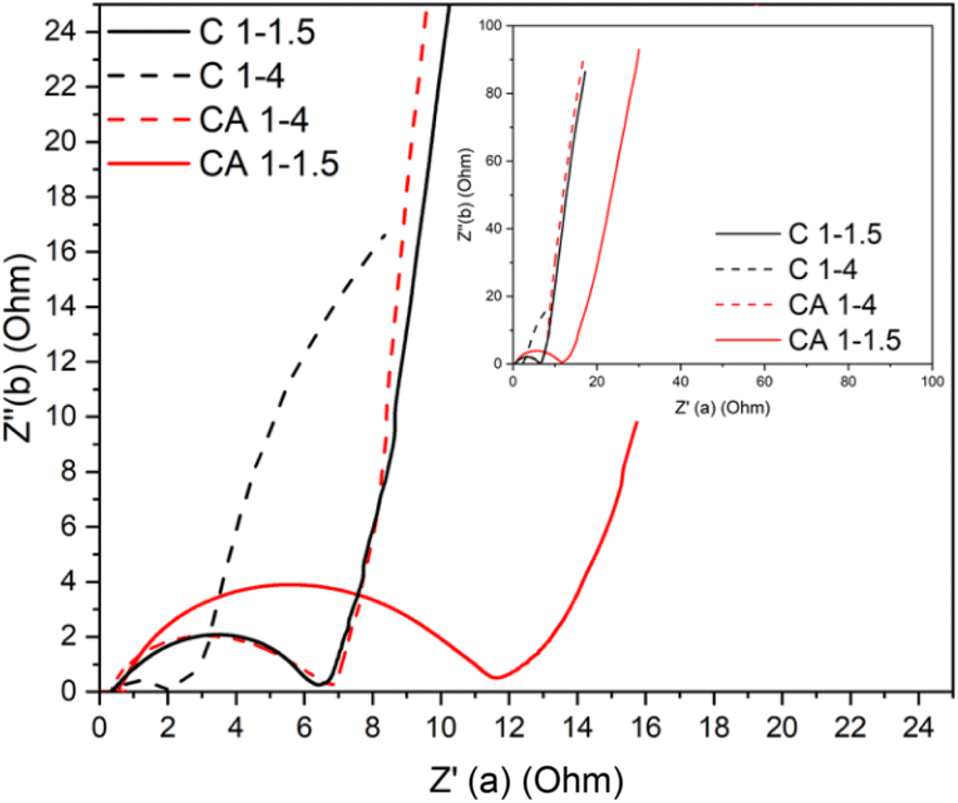 | ||
| Fig. 7 Nyquist plot calculated from impedance spectroscopy tests. | ||
The Nyquist graph in Fig. 7 shows a similar trend to the galvanostatic results. The sample with the highest capacitance (as well as power and energy densities) consequently presents the smallest semicircle, meaning that charge transfer resistance in this sample is minimal compared to the rest of the produced samples.
Based on the galvanostatic and impedance results, we can conclude that the C 1–4 sample presents the highest electrochemical performance, followed by its nitrogen-doped counterpart (CA 1–4). Following this trend, albumin-doped CA 1–1.5 displays poorer performance than C 1–1.5, as depicted in Fig. 8.
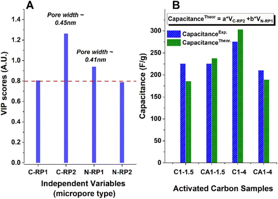 | ||
| Fig. 8 Relationship between pore width and capacitance in activated carbons (ACs) C 1–1.5, CA 1–1.5, C 1–4, and CA 1–4, analysed using partial least squares regression. The VIP scores are shown in graph (A), helping to determine the most important parameters influencing the capacitance (they are above the red dot line). Graph (B) compares the estimated capacitance values (based on two pore types, N-RP3 and C-RP2) with the experimental capacitance values for these samples. | ||
To identify the pore size impact on capacitance performance of the prepared electrode materials, Partial Least Square (PLS) regression analysis of the data was employed using OriginPro 2023b (64-bit) software. PLS is a statistical method to model complex relationships between multiple independent (predictor) and dependent (response) variables.42 PLS is particularly useful when the predictor variables are highly colinear or when the number of predictor variables exceeds the number of observations. In the context of PLS regression, Variable Importance in Projection (VIP) scores were used to quantify the importance of each predictor variable of these contributions. It was established from the literature that VIP values less than 0.8 (red dot line in Fig. 8A) have minimal impact and, therefore, may be excluded from the model.43
Variables within the 0.8–1.0 range have moderate importance, whereas variables with VIP scores greater than 1.0 are generally considered to have a significant impact.44 Based on VIP scores (Fig. 8A), insignificant contributors like pores C-RP1 (with width 0.38 nm) and N-RP2 (width 0.55 nm) were omitted from the model. The analysis was narrowed down to two pores (N-RP1 and C-RP2) with the most significant contributions. To check the suitability of the findings, the capacitance of the samples was estimated based on the volume of these two types of pores according to the equation presented in Fig. 8B, and compared against the actual capacitance data obtained experimentally through a linear regression analysis (yielding an adjusted R-square of 0.982).
The two types of pores that best describe the efficiency of the ACs as supercapacitors have similar diameters of 0.41 and 0.45 nm (pore C-RP2, with a diameter of 0.45 nm, as can be seen contributes the most). At the same time, pores with both a smaller diameter (0.37 nm) and a larger one (0.52 and 0.72 nm) have significantly less influence on the performance of the supercapacitors tested with the chosen electrolyte. The size of the pore, around 0.43 nm, is very close to the diameter of sulfate anion (SO42−), which is 0.426 nm, so this anion is well-suited to the most efficient pore, indicating a good fit for efficient ion transport of sulfate-anion (a 2 M H2SO4 aqueous solution was used as an electrolyte in this experiment).
Table 7 compares the electrochemical performance of our sample to other carbonaceous electrodes developed by HTC. To the authors' knowledge, this hydrothermally treated, biomass-derived carbon displays an outstanding electrochemical performance that has not been seen in other HTC-prepared biomass-based electrodes. It must also be noted that the prepared carbon exhibits the highest capacitance, outperforming other carbons with a pseudocapacitive contribution45,48,51 or more complex pore generation methods, such as physico-chemical activation.46 Its high microporosity and near-ideal pore diameter in relation to the electrolyte ion size are most likely critical factors for this superior performance.
| Electrode | Electrolyte | Porosity | S BET (m2 g−1) | C max (F g−1) |
|---|---|---|---|---|
| Cellulose | 2 M H2SO4 | 95% microporosity | 1674 | 275 |
| Chitosan45 | 1 M H2SO4 | 36% microporosity | 2124 | 274 |
| Coconut shells46 | 0.5 M H2SO4 | Mesoporous structure | 2440 | 246 |
| Wood sawdust47 | 6 M KOH | 74% microporosity | 1185 | 244 |
| Enteromorpha prolifera 48 | 6 M KOH | 88% microporous | 1528 | 228 |
| Cellulose49 | 1 M TEABF4/AN | 87% microporosity | 2457 | 180 |
| Starch49 | 1 M TEABF4/AN | 87% microporosity | 2273 | 180 |
| Jatropha50 | 1 M KOH | Large micro and macropores | 747 | 175 |
| Lignin51 | 6 M KOH | Mainly microporous structure | 1337 | 130 |
| Corn straws52 | 6 M KOH | Mainly microporous | 1229 | 75 |
4. Conclusions and future perspectives
The article examines new sustainable approaches for obtaining electrodes for supercapacitors from cellulose. It was proposed to apply the preliminary HTC step of cellulose at 200 °C before its final pyrolysis at 800 °C. It was shown that such an approach substantially reduces the formation of volatile compounds and increases the final yield of carbon from 6% to 50% (see Fig. S4†), promoting eco-friendliness and outperforming the conventional methods to produce supercapacitor electrodes.To increase the efficiency of sustainable supercapacitors, the influence of char activation methods was investigated. Two different ratios of KOH to cellulose (1.5:1 and 4:1) were used for activation, resulting in highly microporous materials with pore sizes ranging from 0.35 to 0.75 nm and a specific surface area (SBET) exceeding 1200 m2 g−1.
Thus, our study highlights the significant effect of nitrogen (N) doping of carbonaceous precursors on the pore structure of obtained activated carbons. Although this modification changes the pore size distribution, it did not improve the characteristics of the electrodes under the conditions of our experiment, due to the relatively low doping level achieved. Nevertheless, the results of our research contribute to a deep understanding of how these electrodes function.
The main conclusion of this study is that, to achieve optimal capacitance, it is crucial to obtain a more precise match between the micropore size in the electrodes and the electrolyte ions. In particular, we found that pores with a width of approximately 0.43 nm provide the best performance characteristics since this size is ideal for accommodating the sulphate ions involved in the electrochemical processes of these supercapacitors.
Furthermore, our results underscore the potential advantages of nitrogen doping of biomass prior to chemical activation for AC pore structure modification. We believe that the final materials can be adjusted for optimal electrode efficiency under certain preparation conditions. The optimization of variables such as the starting materials, nature and concentration of N-containing materials, and activation processes employed are essential. The potential and versatility of this approach paves the way for further enhancement of electrode materials in energy storage systems.
Data availability
The data supporting this article have been included as part of the ESI.†Author contributions
Manuel Prieto: data curation; formal analysis; investigation; methodology; visualization; writing – original draft; writing – review & editing; Gary J. Ellis: funding acquisition; writing – review & editing; Enrique Morales: data curation; methodology; supervision; writing – review & editing; Vitaliy Budarin: formal analysis; visualization; writing – original draft; Mohammed Naffakh: funding acquisition; writing – review & editing; Peter S. Shuttleworth: conceptualization; funding acquisition; investigation; methodology; resources; supervision; visualization; writing – original draft; writing – review & editing.Conflicts of interest
There are no conflicts to declare.Acknowledgements
This research was funded by NextGeneration EU via SusPlast; FEDER/Ministerio de Ciencia, Innovación y Universidades-Agencia Estatal de Investigación/MAT2017-84691-P; Subprograma Estatal de Incorporación/IED2019-001134-I; Consejería de Educación e Investigación de la Comunidad de Madrid y del Fondo Social Europeo/PEJD-2019-PRE/IND-16080; Spanish Ministry of Science and Innovation (Project SPoNaFun, PID2020-117573GB-I00); CSIC Program for Scientific Cooperation with Ukraine (No. UCRAN20080). MP would also like to acknowledge CSIC for IMOVE grant (IMOVE23076), for funding a research placement at ICGM-CNRS, where XPS and N2 sorption analyses were carried out under the guidance of Dr Nicolas Brun. The authors also appreciate the assistance of BSc student Beatriz Bispo de Souza for sample preparation and characterization.Notes and references
- P. Gerland, A. E. Raftery, H. Ševčíková, N. Li, D. Gu, T. Spoorenberg, L. Alkema, B. K. Fosdick, J. Chunn, N. Lalic, G. Bay, T. Buettner, G. K. Heilig and J. Wilmoth, Science, 2014, 346, 234 CrossRef PubMed.
- Global Energy Statistical Yearbook 2020, United Nations Energy Statistics Yearbook, 2020, https://unstats.un.org/unsd/energystats/pubs/yearbook/ Search PubMed.
- IEA, Global Energy Review 2021, IEA, Paris, 2021, https://www.iea.org/reports/global-energy-review-2021 Search PubMed.
- Electricity Prices in Europe – Who Pays the Most?, https://strom-report.com/electricity-prices-europe/, accessed 01-06-2024.
- S. Kumar, G. Saeed, L. Zhu, K. N. Hui, N. H. Kim and J. H. Lee, Chem. Eng. J., 2021, 403, 126352 CrossRef.
- M. Winter and R. J. Brodd, Chem. Rev., 2004, 104, 4245–4270 CrossRef PubMed.
- J. Garche and P. T. Moseley, Electrochemical Energy Storage for Renewable Sources and Grid Balancing, Elsevier, Oxford, NETHERLANDS, 2014 Search PubMed.
- P. Kurzweil, in Electrochemical Energy Storage for Renewable Sources and Grid Balancing, ed. P. T. Moseley and J. Garche, Elsevier, Amsterdam, 2015, pp. 345–407, DOI:10.1016/B978-0-444-62616-5.00019-X.
- M. Moreno Fernández, Types of electrolytes for carbon-based supercapacitors, Doctoral Thesis, Universidad Autónoma de Madrid, 2016.
- G. Wang, L. Zhang and J. Zhang, Chem. Soc. Rev., 2012, 41, 797–828 RSC.
- B. O. K. Park, C. D. Lokhande, H. S. Park, K. D. Jung and O. H. S. Joo, J. Mater. Sci., 2004, 39, 4313–4317 CrossRef.
- M. Prieto, H. Yue, N. Brun, G. J. Ellis, M. Naffakh and P. S. Shuttleworth, Polymers, 2024, 16, 2633 CrossRef PubMed.
- M. Boota and Y. Gogotsi, Adv. Energy Mater., 2019, 9, 1802917 CrossRef.
- S. Zhang, J. Liu, P. Huang, H. Wang, C. Cao and W. Song, Sci. Bull., 2017, 62, 841–845 CrossRef CAS.
- L. Lyu, H. Chai, K. D. Seong, C. Lee, J. Kang, W. Zhang and Y. Piao, Electrochim. Acta, 2018, 291, 256–266 CrossRef CAS.
- S. Abu-Ghosh, V. Kumar, D. Fixler, Z. Dubinsky, A. Gedanken and D. Iluz, Algal Res., 2017, 23, 161–165 CrossRef.
- C. Liu, Z. Yu, D. Neff, A. Zhamu and B. Z. Jang, Nano Lett., 2010, 10, 4863–4868 CrossRef CAS.
- Y. Wang, Z. Shi, Y. Huang, Y. Ma, C. Wang, M. Chen and Y. Chen, J. Phys. Chem. C, 2009, 113, 13103–13107 CrossRef CAS.
- Y. Zhu, S. Murali, M. D. Stoller, K. J. Ganesh, W. Cai, P. J. Ferreira, A. Pirkle, R. M. Wallace, K. A. Cychosz, M. Thommes, D. Su, E. A. Stach and R. S. Ruoff, Science, 2011, 332, 1537–1541 CrossRef CAS PubMed.
- C. G. Liu, M. Liu, F. Li and H. M. Cheng, Appl. Phys. Lett., 2008, 92(14), 143108 CrossRef.
- H. Pan, J. Li and Y. P. Feng, Nanoscale Res. Lett., 2010, 5, 654–668 CrossRef CAS PubMed.
- M. V. Kiamahalleh, S. H. S. Zein, G. Najafpour, S. A. Sata and S. Buniran, Nano, 2012, 7(02), 1230002 CrossRef.
- T. Prasankumar, D. Salpekar, S. Bhattacharyya, K. Manoharan, R. M. Yadav, K. A. Miller, R. Vajtai, S. Jose, S. Roy and P. M. Ajayan, Carbon, 2022, 199, 249–257 CrossRef CAS.
- W. Li, G. H. Wang, W. J. Sui, T. Xu, Z. F. Li, A. M. Parvez and C. L. Si, Carbon, 2022, 196, 819–827 CrossRef CAS.
- Q. Q. Li, Y. T. Jiang, Z. M. Jiang, J. Y. Zhu, X. M. Gan, F. W. Qin, T. T. Tang, W. X. Luo, N. N. Guo, Z. Liu, L. X. Wang, S. Zhang, D. Z. Jia and Z. J. Fan, Carbon, 2022, 191, 19–27 CrossRef CAS.
- Position of European Bioplastics-Industrial Use of Agricultural Feedstocks, European Bioplastics, Berlin, Germany, 2019, available at: https://www.european-bioplastics.org/industrial-use-of-agricultural-feedstock/ Search PubMed.
- A. Kazmi and P. S. Shuttleworth, The Economic Utilisation of Food Co-products, The Royal Society of Chemistry, 2013 Search PubMed.
- M. Sevilla and A. B. Fuertes, Carbon, 2009, 47, 2281–2289 CrossRef CAS.
- S. Xu, H. He and L. Luo, in Recycling of Solid Waste for Biofuels and Bio-Chemicals, ed. O. P. Karthikeyan, K. Heimann and S. S. Muthu, Springer Singapore, Singapore, 2016, pp. 31–54, DOI:10.1007/978-981-10-0150-5_2.
- T. Wang, Y. Zhai, Y. Zhu, C. Li and G. Zeng, Renewable Sustainable Energy Rev., 2018, 90, 223–247 CrossRef CAS.
- M.-M. Titirici and M. Antonietti, Chem. Soc. Rev., 2010, 39, 103–116 RSC.
- L. L. Baxter, T. R. Miles, T. R. Miles, B. M. Jenkins, T. Milne, D. Dayton, R. W. Bryers and L. L. Oden, Fuel Process. Technol., 1998, 54, 47–78 Search PubMed.
- F. Mbarki, T. Selmi, A. Kesraoui, M. Seffen, P. Gadonneix, A. Celzard and V. Fierro, Ind. Crops Prod., 2019, 140, 111717 CrossRef.
- J. R. Mohrig, Techniques in Organic Chemistry, W. H. Freeman, 2002 Search PubMed.
- T. Sharifi, F. Nitze, H. Barzegar, C.-W. Tai, M. Mazurkiewicz, A. Malolepszy, L. Stobinski and T. Wågberg, Carbon, 2012, 50, 3535–3541 CrossRef.
- G. Azuara-Tuexi, E. Muñoz-Sandoval and R. A. Guirado-López, Phys. Chem. Chem. Phys., 2023, 25, 3718–3736 RSC.
- M. Thommes, K. Kaneko, A. Neimark, J. Olivier, F. Rodriguez-Reinoso, J. Rouquerol and K. Sing, Pure Appl. Chem., 2015, 87(9), 1051–1069 CrossRef.
- K. Cychosz and M. Thommes, Engineering, 2018, 4(4), 559–566 CrossRef.
- S. Adamu, M. Y. Khan, S. A. Razzak and M. M. Hossain, J. Porous Mater., 2017, 24, 1343–1352 CrossRef CAS.
- M. Richou, C. Martin, R. Denoyel, P. Llewellyn and P. Roubin, Carbon, 2009, 47, 109–116 CrossRef CAS.
- M. M. Dubinin and H. F. Stoeckli, J. Colloid Interface Sci., 1980, 75, 34–42 CrossRef CAS.
- W. W. C. Vincenzo Esposito Vinzi, J. Henseler, Huiwen Wang Handbook of Partial Least Squares: Concepts, Methods and Applications, Springer, 2010 Search PubMed.
- G. D. Garson, Partial Least Squares: Regression and Structural Equation Models, Statistical Associates Publishers, Asheboro, 2016 Search PubMed.
- D. Cheng, Y. Feng, Y. Liu, J. Li, J. Xue and Z. Li, Sci. Total Environ., 2018, 634, 1148–1156 CrossRef CAS.
- X. Tong, Z. Chen, H. Zhuo, Y. Hu, S. Jing, J. Liu and L. Zhong, Carbohydr. Polym., 2019, 207, 764–774 CrossRef CAS PubMed.
- A. Jain, C. Xu, S. Jayaraman, R. Balasubramanian, J. Y. Lee and M. P. Srinivasan, Microporous Mesoporous Mater., 2015, 218, 55–61 CrossRef CAS.
- L. Yang, Y. Feng, M. Cao and J. Yao, Mater. Chem. Phys., 2019, 238, 121956 CrossRef CAS.
- M. Ren, Z. Jia, Z. Tian, D. Lopez, J. Cai, M.-M. Titirici and A. B. Jorge, ChemElectroChem, 2018, 5, 2686–2693 CrossRef CAS.
- L. Wei, M. Sevilla, A. B. Fuertes, R. Mokaya and G. Yushin, Adv. Energy Mater., 2011, 1, 356–361 CrossRef CAS.
- M. Siva Sankari and S. Vivekanandhan, ChemistrySelect, 2020, 5, 1375–1384 CrossRef CAS.
- H. Li, F. Shi, Q. An, S. Zhai, K. Wang and Y. Tong, Int. J. Biol. Macromol., 2021, 166, 923–933 CrossRef CAS.
- H. Ma, Z. Chen, X. Wang, Z. Liu and X. Liu, J. Renewable Sustainable Energy, 2019, 11, 024102 CrossRef.
Footnote |
| † Electronic supplementary information (ESI) available. See DOI: https://doi.org/10.1039/d4ta04477k |
| This journal is © The Royal Society of Chemistry 2024 |