DOI:
10.1039/D4TA04141K
(Paper)
J. Mater. Chem. A, 2024,
12, 29708-29725
Non-thermal plasma enabled catalytic dry reforming of methane over a ceria nanorod supported NiO catalyst: the role of Ru as a coke resistant active site†
Received
15th June 2024
, Accepted 19th September 2024
First published on 19th September 2024
Abstract
This study reports that a 14 wt% Ni–1 wt% Ru bimetallic catalyst supported on ceria (CeO2) nanorods (NRs) synthesized via wet impregnation can offer superior conversion and stability against coking during non-thermal plasma (NTP)-assisted dry reforming of methane (DRM) compared to monometallic Ni or Ru catalysts. This study revealed that when Ru was introduced as a promoter into the CeO2 NR supported Ni catalyst, the DRM conversion percentage increased significantly under NTP (CH4: 92% and CO2: 70%) at 450 °C. Unlike thermal catalysis, plasma catalysis resulted in high yield (46% CO and 40% H2) and selectivity (62% CO and 42% H2) at 450 °C. Additionally, the durability (60 minutes) of the catalyst was tested at 350 °C. The bimetallic synergy and formation of CeO2 NR supported Ni–O–Ru solid solution are believed to be the main causes of the significantly improved CH4 and CO2 conversions. The high coking resistance of the CeO2-NR supported Ni–Ru bimetallic catalyst is attributed to three major factors: (1) the role of Ru in weakening the bond between Ni sites and carbon; (2) the higher dispersion of Ni over the CeO2 NR surface; and (3) the accessibility of surface and lattice oxygen over the CeO2 NR support, which promotes excellent redox properties and carbon oxidation. The proposed non-equilibrium and bimetallic synergy approach paves the way for cost-efficient and durable DRM catalysts for scalable syngas production from two potent greenhouse gases, which could potentially apply to future energy-efficient industrial processes such as the production of syngas and other value-added chemicals.
1. Introduction
The depletion and environmental concerns associated with the consumption of fossil fuel resources have driven the energy industry to search for alternative strategies. Because of the abundance and accessibility of feedstocks, dry reforming of methane (DRM) is a readily scalable gas reforming technology for refining two primary greenhouse gases (GHGs), namely, carbon dioxide (CO2) and methane (CH4), to syngas (a mixture of CO and H2) (eqn (1)). Syngas is a vital chemical energy source for the Fischer–Tropsch synthesis of value-added fuels and chemicals.1,2| | | CH4(g) + CO2(g) ⇌ 2CO(g) + 2H2(g) | (1) |
Nevertheless, DRM is an endothermic procedure that requires excess thermal energy (>700 °C).3 The spontaneous reaction is thermodynamically impossible at low temperatures considering that negative Gibbs free energy is not fulfilled. Non-thermal plasma (NTP) or cold plasma technology offers a viable alternative to the traditional catalytic approach for DRM conversion owing to its non-thermal and non-equilibrium properties, lower energy demand, and unique ability to trigger chemical and physical reactions at relatively low temperatures. In NTP, the average kinetic temperature of the gas stays low. In contrast, energetic electrons with a typical electron temperature of 10![[thin space (1/6-em)]](https://www.rsc.org/images/entities/char_2009.gif) 000–100000 K (1–10 eV) can split inert CO2 and CH4 molecules to generate extremely activated species such as ionized particles, molecules, and free radicals. Hence, electron temperature rather than thermal processes drives chemical reactions under NTP.4–6Eqn (2)–(4) present a few examples of easy NTP integrated electron impact dissociation of CH4 and CO2, which require relatively high temperatures for conventional thermal dissociation.
000–100000 K (1–10 eV) can split inert CO2 and CH4 molecules to generate extremely activated species such as ionized particles, molecules, and free radicals. Hence, electron temperature rather than thermal processes drives chemical reactions under NTP.4–6Eqn (2)–(4) present a few examples of easy NTP integrated electron impact dissociation of CH4 and CO2, which require relatively high temperatures for conventional thermal dissociation.
| |  | (2) |
| |  | (3) |
| | | CO2 + e− ⇌ CO + O* + e− | (4) |
Since CH4 and CO2 have relatively stable chemical structures and dry reforming feedstocks typically have a higher carbon deposition, obtaining a high selectivity and yield from CH4 and CO2 reforming requires specialized or complicated techniques. Thus, various catalysts or supported catalysts have been utilized to activate the C–H and C–O bonds in stable CH4 and CO2 reactants. Prior research has demonstrated that although the catalyst sources for DRM can be group VIII metals from the periodic table, i.e., Ru, Rh, Pt, Co, and Ni, from a commercial perspective, Ni is the most suitable or sustainable catalyst material especially because it is affordable and easily accessible.7,8 However, the catalyst deactivation induced by the potential deposition of coke on catalysts is the primary barrier to its industrial application at the present time. According to scientific literature, the coking issue can be addressed using promoters like noble metals including Ru and Pt, which promote the activation of H2 from CH4 dissociation or dehydrogenation (H2 spillover effect) and enhance the NiO reduction at lower temperature.9,10 Besides, it has been reported that bimetallic catalysts can outperform their monometallic counterparts in terms of conversion, yield, selectivity, and coke resistance.11–13 For instance, Duan et al.14 reported reduced carbon deposition for Mg(Al)O supported bimetallic Ni9Co3 (31 wt%) and Ni6Co6 (21 wt%) catalysts in DRM reaction, which is much better than monometallic Ni9 (66 wt%) and Ni6 (40 wt%) with a similar Ni content and support material. Similarly, Zafarnak et al.15 observed that bimetallic catalysts exceeded monometallic catalysts in terms of DRM activity under the same reaction conditions, indicating a potential synergistic effect of two different metals. According to their report, 10 wt% Ni–10 wt% Co/mullite converted 87% CH4 and 85% CO2 at 750 °C, while 20% Ni/mullite and 20% Co/mullite had a CH4 and CO2 conversion below 80%. Although several catalytic DRM experiments are available in the literature, most of these are conventional thermal catalytic DRM. However, this research remarkably blends the advantages of NTP and bimetallic synergy of Ni and Ru catalysts on a surface-engineered CeO2 NR support, which established significant improvements of low-temperature conversion compared to conventional thermal DRM.
In this study, CeO2 NR supported 14 wt% Ni and 1 wt% Ru catalysts were synthesized by a wet impregnation method and assessed for DRM under thermal and non-thermal plasma environments. The correlation between catalytic activity and catalyst properties was investigated using XRD, Raman, TPR, TPD, XPS, and TEM techniques.
2. Materials and methods
2.1 Catalyst synthesis
2.1.1 Chemicals.
Cerium(III) nitrate hexahydrate (Ce(NO3)3·6H2O, 99.5% pure) was bought from Acros Organics. Both sodium hydroxide (NaOH, 99% pure) and ammonium hydroxide (NH3·H2O, BDH, 28–30 vol%) were acquired from VWR. The catalyst precurors were ruthenium nitrosyl trinitrate [Ru(NO)(NO3)3] and nickel(II) nitrate hexahydrate [Ni(NO3)2·6H2O] from Alfa Aesar, both of which were 99.9% pure. The compounds were utilized without any additional processing.
2.1.2 Preparation of the CeO2 NR support.
To prepare 88 mL of 0.1 M Ce(NO3)3·6H2O solution, 3.8403 g of Ce(NO3)3·6H2O was added to 88 mL of DI (deionized) water.16–18 Simultaneously, 1.93 g of NaOH was dissolved in 8 mL of DI water to prepare an aqueous solution of 6 M NaOH. Then, the 8 mL solution of NaOH (6.0 M) was mixed drop by drop with the 88 mL solution of Ce(NO3)3·6H2O (0.1 M) and stirred vigorously in a 200 mL Teflon autoclave liner. The solution was mixed for 15 seconds prior to transferring the Teflon liner to an autoclave made of stainless steel and sealing it carefully. The autoclave was kept in an oven for 48 hours at 90 °C. The autoclave was subsequently lowered to ambient temperature, and the precipitate was thoroughly washed with approximately 500 mL of DI water to eliminate any leftover NO3 and Na+ ions. The CeO2 NR were cleaned with 50 mL of ethanol to prevent hard aggregation and baked for 12 hours at 60 °C. The support was then collected and crushed with a mortar and pestle.
2.1.3 Preparation of Ni–Ru/CeO2 NR bimetallic catalysts.
Ru and Ni were loaded on the CeO2 NR support via wet impregnation with aqueous Ru(NO)(NO3)3 and Ni(NO3)2·6H2O solutions. In 200 mL beakers, 100 mL of deionized water was combined with 0.85 g of CeO2 NR powder. Under vigorous stirring, 1 wt% Ru equivalent of Ru(NO)(NO3)3 and 14 wt% Ni equivalent of Ni(NO3)2·6H2O precursors were added to the CeO2 NR support powder suspension. The suspension solution was thoroughly mixed by magnetic stirring, and then a solution of NH3·H2O (0.5 M, ammonium hydroxide, BDH, 28–30 vol%) was added slowly to maintain the pH value at ∼9. The precipitate was heated at 80 °C for 4 hours while being stirred at 400 rpm. Afterward, the precipitate was placed in a drying oven for 24 hours at 80 °C. The sample was collected and crushed using a mortar and pestle into a fine powder, and then calcined in a furnace for 5 hours at 350 °C with a ramp of 10 °C min−1.
2.2 Catalyst characterization
Powder X-ray diffraction (XRD) was used to examine the crystal structures of the produced catalysts employing a Phillips X'Pert MPD diffractometer set to a voltage of 40 kV and a current of 40 mA with a copper Kα radiation source (λ = 0.154 nm). Each profile was scanned at 0.5° min−1 with a range of 2θ between 10° and 90°. Jade software was used to examine the lattice properties and average crystal size of each catalyst using the acquired XRD patterns.
The nitrogen adsorption–desorption isotherm at 77 K was used to calculate the Brunauer–Emmett–Teller (BET) surface area using a Micromeritics AutoChem II 2920 chemisorption analyzer. Hydrogen temperature-programmed reduction (H2-TPR) and carbon dioxide temperature-programmed desorption (CO2-TPD) were both characterized using the same apparatus. For the H2-TPR study, 85–95 mg of each powder sample was put in a quartz U-tube sandwiched between two pieces of quartz wool and heated at 10 °C min−1 from 30 °C to 900 °C. The samples were then reduced in a combination of 10% H2 and 90% Ar while maintaining a 50 mL min−1 flow rate. A calibrated thermal conductivity detector (TCD) was used to detect the H2 signal, and the amount of H2 consumed during the reduction was determined (calibrated) by a quantitative reduction of CuO to metallic copper. For the CO2-TPD analysis, the sample was placed in a quartz U-tube with a helium (He) stream (flow rate: 50 mL min−1) and heated from room temperature to 400 °C to eliminate any remaining moisture. Following a 60 minute cool-down period to ambient temperature, the sample was subjected to a gas combination of 10% CO2 and 90% He at a 50 mL min−1 flow rate. Under He gas, the sample was heated linearly until 900 °C at a flow rate of 10 °C min−1. At increased temperatures, the CO2 desorption behavior was evaluated using a TCD.
A transmission electron microscope (TEM, Model: FEI Tecnai F20, 200 kV acceleration voltage) was used to collect high-resolution transmission electron microscopy (HRTEM) images to investigate the particle morphology/size and microstructures. Powder agglomeration and elemental distribution were determined utilizing a JEOL 7000 FE SEM with an energy dispersive X-ray spectrometer (EDX). The powder samples were ultrasonically dispersed in ethanol for TEM sample preparation. Before analysis, a tiny amount of suspension solution (typically one/two drops) was accumulated on an ultrathin carbon film affixed to a 400-mesh copper grid (Ted Pella Inc.) and dried for two hours.
X-ray photoelectron spectroscopy (XPS) analysis was done using a Kratos Axis Ultra DLD spectrometer equipped with a monochromatic Al Kα (hv = 1486.6 eV) source and ultra-high vacuum (10−10 Torr), and the surface chemical composition of the synthesized samples was determined from the obtained profile data. Carbon (C) 1s at 284.8 eV was used to calibrate the XPS binding energies (BE). Using CASA XPS software, the spectrum was fitted and deconvoluted.
A Raman spectrometer (Model: Horiba LabRAM HR 800, objective: 100×) was used to non-destructively characterize the catalysts' elemental coordination environment spanning the spectral range of 100 to 1200 cm−1. A Si single-crystal wafer was used to calibrate the spectrometer prior to each study. Excitation was performed with a laser system (Model: Laser Quantum MPC6000, diode-pumped solid-state) calibrated to λ = 532 nm wavelength.
2.3 Reactor setup
The DRM activity was assessed by placing the catalysts in an atmospheric-pressure fixed-bed dielectric barrier discharge (DBD) reactor system.19,20 The pictorial representation of the complete plasma reactor system is depicted in Fig. 1. The DBD reactor consists of four distinct modules: a gas distribution system, a core quartz reactor system, an experimental regulating section, and a flow gas assessment system. Three Brooks GF040 Multiflo thermal mass flow controllers (MFC) with <1 s response times, MFC-1, MFC-2, and MFC-3, are a part of the gas supply system. These MFCs regulate the CO2, CH4, and Ar streams with a purity of >99.99% from Airgas. The gas flow of MFCs is controlled by a computer interface with a custom MATLAB GUI code through a national instrument (NI) card. The core quartz reactor system comprises two circular quartz tubes inside a furnace (Model: ATS 3210, Max temperature: 1200 °C). During operation, the temperature of the furnace is measured using thermocouples TC1, TC2, and TC3. The internal quartz tube (OD = 6.35 mm) is open-ended and has an expansion part (ID = 9.40 mm, length = 91.78 mm), while the outer quartz tube has a fixed diameter of 25.4 mm and a length of 91.78 mm. Two electrodes, with axial and wrapped shapes, are in the extended portion of the internal reactor tube. For plasma generation, the cathode (Kanthal A-1 wire, 24 g) is placed at the center axis of the tubes, and the anode (Kanthal A-1 wire, 32 g) is coiled around the inner tube's expansion portion. A dielectric barrier is created by covering the center electrode with a nonporous alumina ceramic tube (ID: 0.063 mm). The discharge gap of the electrodes is 6.12 mm. The supply gas system is connected through the internal quartz tube, allowing feed gases to enter first. The reactant gases first interact with the catalysts and plasma inside the inner tube before leaving via the open end. The catalyst sample was blended with quartz wool at the internal quartz tube's expansion section, where the plasma was created. The outer tube with a closed-end changes the gas direction so that it flows out to the exhaust. The exhaust gas mixture was studied utilizing a quadrupole mass spectrometer (QMS, model: MAX300-EGA) and a tunable diode quantum cascade laser absorption spectroscopy (TDLAS) system. The TDLAS system component consists of a quantum cascade laser (QCL) (Alpes Laser, sbcw6200 DN) with a controller as a laser supply, a homemade Herriott cell to improve gas absorption length, an IR detector to detect laser signal or intensity, an oscilloscope (Tektronix TBS1154, 150 MHz), and a waveform generator (B&K Precision, 4055B, 1 Hz to 60 MHz). The QMS collects gas samples from the end of the inner quartz through a small capillary quartz tube (OD: 0.80 mm, ID: 0.53 mm) and measures time-resolved concentration. The catalyst is placed in the plasma region at the expansion section of the inner tube. The TDLAS system collects samples from the exhaust line to detect C-2 products, like C2H6, C2H4, and C2H2, while the QMS system detects CO, H2, CH4, CO2, and Ar. Before the operation, the TDLAS system's precision and the QMS's calibration were tested by flowing a known mixture of gases. A simultaneous stream of all gases (CH4, CO2, H2, CO, O2, and Ar) was required for calibration. A PVM500-2500 AC high-voltage power supply from Amazing1.com was connected to the DBD reactor to make uniform plasma. This power supply has a peak-to-peak voltage of 40 kV and a 20–70 kHz frequency. This study has a power supply frequency of 20 kHz. A high-voltage probe (Model: Tektronix P6015A) and a current transformer (Model: Magnelab, CT-E 0.5 BNC) were utilized to capture the electrical signals (applied voltage and current) in the oscilloscope that was connected to the TDLAS system. Each plasma-assisted DRM cycle comprises a 7 minute reduction cycle and a 3 minute purge with purified Ar gas. During the reduction, a total flow rate of 350 sccm and a ratio of 2.5 (CO2:CH4 = 250:100 sccm) were maintained, while 100% Ar was streamed during the purge cycle to prepare the system for the following DRM cycle. The furnace regulates the reaction zone temperature, ranging between 150 and 450 °C at a rate of 4 °C min−1.
 |
| | Fig. 1 Schematic of the atmospheric pressure DBD plasma reactor with accessories for DRM. | |
2.4 Performance parameters
Conversion, yield, and selectivity are crucial parameters to evaluate the performance of any catalysis system. The conversion calculates the amount of reactant gas converted for every input unit. In a reaction, the selectivity measures the ratio of the desired product formed (in moles) to the portion of converted reactants. In contrast, the yield is the ratio of the desired product formed to the entire amount that is produced (100% yields indicate the absence of side reaction). The following formulas describe the feed gas conversion, product yield, and selectivity of the DRM reaction:| |  | (5) |
| |  | (6) |
| |  | (7) |
| |  | (8) |
| |  | (9) |
| |  | (10) |
| |  | (11) |
| |  | (12) |
3. Results and discussion
3.1 Material characterization
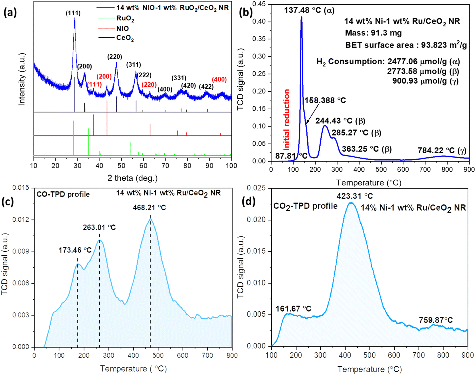
The XRD profile of the CeO2 NR supported Ni–Ru bimetallic catalyst is shown in Fig. 2(a). Fig. 2(a) exhibits a major phase corresponding to the face-centered cubic fluorite structure of CeO2 with the space group of Fm3m (JCPDS #34-0394). The observed peaks at 28.5°, 33.1°, 47.5°, 56.3°, 59.1°, 69.4°, 76.7°, and 79.1° correspond to (111), (200), (220), (311), (222), (400), (331), (420), and (422) planes of the CeO2 structure, respectively. As seen, 14 wt% NiO–1 wt% RuO2/CeO2 NR exhibits broad and less intense peaks, indicating that the crystallite size is small. With the help of the Scherrer formula and XRD peak assessment, the size of the CeO2 crystallite was determined to be ∼4 nm. Although an independent RuO2 phase could not be distinguished on XRD, multiple tiny peaks at 2θ of ∼37°, 43°, 63°, and 95° suggest the existence of NiO (JCPDS #47-1049) in the 14 wt% NiO–1 wt% RuO2/CeO2 NR.21,22 The observed data indicates that NiO nanoparticles have a size of about 2 nm. The formation of Ni–Ru–Ce–O solid solution or NiO and RuO2 diffusion into the CeO2 NR lattice might explain the lack of RuOx (0 ≤ x ≤ 1) and broader NiO diffraction peaks in the XRD pattern. The small RuO2 loading (1 wt%) is also a possible reason for the absence of the RuOx phase. Fig. 2(b) shows the H2-TPR profile of the 14 wt% NiO–1 wt% RuO2/CeO2 NR catalyst. As reported in our previous experiment,23 the reduction peaks (or H2 consumption peaks) of CeO2 NR occur between 300 °C and 600 °C, assigned as β-type phases, and a high temperature (>600 °C) bulk reduction peak of Ce4+ is assigned as γ phase. The typical H2 consumption by CeO2 NR starting at about 300 °C is ascribed to the surface reduction from Ce4+ to Ce3+. However, incorporating Ni and Ru enhances the low temperature reduction of CeO2 over the surface, which takes place at temperature below 300 °C. In the region below 200 °C (α peak), the 14 wt% NiO–1 wt% RuO2/CeO2 NR catalyst shows a couple of reduction peaks at 137.4 °C and 158.3 °C as a consequence of the Ni–Ru–Ce–O solid solution and multiple oxidation states of RuOx due to the chemical linking between RuOx and CeO2.24 At temperatures between 200 and 600 °C, two reduction peaks overlap the region for NiO reduction at about 244.4 °C and 285.2 °C, represented by β.25 These peaks are assigned to the reduction of NiO, following the literature values.26 The bimetallic 14 wt% NiO–1 wt% RuO2/CeO2 NR sample exhibits a low-temperature NiO reduction peak at 285.2 °C compared to the monometallic NiO/CeO2 NR sample at 356 °C.27 This observation agrees with the literature data,28 demonstrating that Ru can aid in the reduction of NiO and CeO2 as a result of hydrogen spillover. In general, the α and β peaks are attributed to the reduction of the Ru and Ni incorporated in the CeO2 lattice or the Ru–Ni–O–Ce solid solution. The solid solution is formed by replacing Ce4+ with Run+ and Ni2+, which generates a charge imbalance and lattice distortions within the CeO2 NR lattice, developing high-concentration oxygen vacancies. Another high-temperature reduction peak, denoted by γ, is observed at 784.2 °C, which is assigned as the bulk reduction of CeO2 NR.29 Hence, it is clear that the low temperature lattice oxygen release capability of bimetallic 14 wt% NiO–1 wt% RuO2/CeO2 NR is significantly improved compared to the CeO2 NR supported monometallic catalyst counterparts, which is beneficial to low-temperature DRM.30 For better comparison, the H2-TPR, CO2-TPD and CO-TPD profiles of the CeO2 NR support, NiO, RuO2, 15 wt% NiO/CeO2 NR, 1 wt% RuO2/CeO2 NR and 14 wt% NiO–1 wt% RuO2/CeO2 NR are presented in the ESI (Fig. S9 to S11).†
 |
| | Fig. 2 (a) XRD pattern, (b) H2-TPR, (c) CO-TPD, and (d) CO2-TPD profiles of the fresh 14 wt% NiO–1 wt% RuO2/CeO2 NR catalyst. | |
CO is one of the crucial products of the DRM reaction. Therefore, the CO-TPD profile of the 14 wt% NiO–1 wt% RuO2/CeO2 NR catalyst is presented in Fig. 2(c). Three desorption peaks were observed at temperatures of 173.4 °C, 263 °C, and 468.2 °C. Here, lower temperature peaks (<400 °C) are attributed to the desorption of weakly adsorbed CO species, while higher temperature peaks (>400 °C) are attributed to the desorption of strongly adsorbed CO species.31 For instance, Li et al.32 reported that adding a rare earth (La) promoter to the Ni catalyst increases the d-electron density of Ni. The weakened ability to accept paired electrons from CO reduces CO adsorption over the catalyst surface. Therefore, CO desorption is easier on the surface of Ni catalysts with a rare earth promoter, hindering the CO disproportionation. They concluded that the resistance to carbon deposition is, accordingly, extensively promoted. As shown in Fig. 2(c), similarly, due to the Ni–Ru synergism and strong metal (Ni/Ru)–support (CeO2) interaction, the 14 wt% NiO–1 wt% RuO2/CeO2 NR catalyst demonstrates superior low-temperature CO desorption behavior compared to Li et al.'s results.24 Thus, the possibility of carbon deposition over the surface of the CeO2 NR supported Ni–Ru bimetallic catalyst is smaller.
It is worth mentioning that the DRM reaction starts with acid–base interactivity, in which the acid draws towards the base where the catalyst behaves as a base and CO2 as an acid. Hence, the activation of CO2 (acidic nature) varies on the surface of the catalyst, which regulates the stability of the catalyst and the amount of conversion. Thus, CO2-TPD experiments were performed to get a deeper insight into the CO2 adsorption and desorption behavior and the nature of the various basic sites on the synthesized catalyst. As shown in Fig. 2(d), the CO2-TPD profile demonstrates the surface basicity characteristics of the CeO2 NR supported Ni–Ru bimetallic catalyst. Three distinct desorption peaks were visible in the CO2-TPD pattern, which ranged in temperature from 100 to 900 °C. These peaks in Fig. 2(d) are associated with the chemisorption of CO2, which consists of three essential group class contributions, corresponding to (1) weak Brønsted basic sites (such as surface OH groups), (2) medium-strength Lewis basic sites, and (3) strong basic sites represented by low-coordination oxygen anions.33 Thus, those three desorption peaks were observed at three temperature zones: 161.6 °C, 423.3 °C, and 759.8 °C, corresponding to weak, moderate, and strong basic sites, respectively, as depicted in Fig. 2(d). According to the literature, at 100–200 °C and 300–500 °C, the weak and moderate adsorptions correlate to the development of bridging and bidentate carbonates, respectively.34,35 The formation of carboxylate and monodentate carbonates is responsible for the high-temperature peaks at >500 °C (strong adsorption).36 As shown in Fig. 2(d), it is clear that the amount of CO2 absorbed by moderate sites centered at 423.3 °C was far more significant than that of weak and strong basic sites. As pointed out in the literature,37,38 catalysts with medium strength Lewis acid–base basic sites perform better for CO2 absorption and activation as well as coke resistance. These sites promote the chemisorption of acidic CO2 and the reaction between CO2 and CH4, thereby facilitating the desired reforming reactions and minimizing coke formation according to the following reverse Boudouard reaction:
Desorption of CO2 on weak and moderately basic sites increases the production of active carbonate species at the metal–support interface. In contrast, desorption of CO2 on strong basic sites may cause rapid breakdown of CH4 and carbon deposition on active metal catalysts. The intermediate active carbonate species can produce CO via the interaction of O from carbonate species and C from CH4 breakdown through the reaction with CH4. Nevertheless, the residual carbonate species can also generate CO gas. According to the literature, CO2 activation is easier on medium-strength basic sites than strong basic sites.39 Thus, the low temperature and Lewis acid–base medium strength desorption peaks reveal significantly moderate basic sites, indicating a strong synergistic effect on the catalyst, hence accelerating DRM.
XPS characterization was performed to comprehend the valence states of Ni and Ru as well as the surface chemistry of the catalysts. Fig. 3(a)–(d) shows the XPS profiles of the 1s orbital of O, the 2p orbital of Ni, and the 3d orbitals of Ru and Ce. The Ni 2p orbital for the 14 wt% Ni–1 wt% Ru/CeO2 NR catalyst in Fig. 3(a) shows multiplet splitting peaks with two different components. These two peaks are attributed to Ni–Ni or Ni0 and Ni–O or Ni2+. The recorded binding energies (BE) for these two peaks are 852.2 eV and 853.9 eV, respectively.40 The satellite peak adjacent to the main peaks is observed at BE = 860 eV. The Ru 3d XPS profile reveals four distinct Ru peaks (Fig. 3(b)), which are attributed to Ru6+ 3d3/2, Run+ 3d3/2 (4 < n< 6), Ru6+ 3d5/2, and Run+ 3d5/2 (4 < n< 6), respectively. The Ru6+ peaks appeared at 280.7 eV and 288 eV, while the Run+ peaks appeared at 280.2 eV and 286.2 eV. These intense peaks coincide with the C 1s peak at 284.1 eV. The presence of Run+ peaks suggests that electrons may be transferred from RuOx to NiOx or CeO2−x, promoting the solid solution formation of Ru–Ni–O–Ce and/or increasing oxygen vacancy concentration.41 In Fig. 3(c), the deconvolution of the broad O 1s peak reveals multiple oxygen states, which are assigned to lattice oxygen (OL), oxygen vacancies (OV), and hydroxyl oxygen or chemisorbed oxygen (OC), centered at 528.1 eV, 531.6 eV, and 533.8 eV, respectively. The percentage of these oxygen-related species is estimated using the following formula, which results in a relative oxygen vacancy concentration of 28.3%.
| | | [OV]% = [OV/(OV + OL)] × 100 | (14) |
 |
| | Fig. 3 XPS spectra of (a) Ni 2p, (b) Ru 3d, (c) O 1s, and (d) Ce 3d for the 14 wt% Ni–1 wt% Ru/CeO2 NR catalyst. | |
This result indicates that a large amount of oxygen vacancies may aggregate on the surface of the 14 wt% Ni–1 wt% Ru/CeO2 NR catalyst and stimulate the DRM reaction. It is believed that the low-temperature H2 consumption at α and β peaks shown in Fig. 2(b) is related to these surface oxygen defects (Fig. 3(c)).
Fig. 3(d) illustrates the deconvoluted core level spectrum of Ce 3d for the CeO2 NR supported Ni and Ru catalyst. The data shows that Ce4+ 3d presents four distinct peaks at 881 eV, 887.7 eV, 896.6 eV, and 897.5 eV, denoted by V′, V′′, V′′′, and U′, respectively. U and V represent the Ce 3d3/2 and Ce 3d5/2 states, respectively. The presence of Ce3+ ions originating from Ce 3d5/2 and Ce 3d3/2 is responsible for the peaks at 882.5 eV (V°) and 899.5 eV (U°), respectively. According to the literature, Ce3+ strongly indicated the formation of oxygen vacancies, which is also acknowledged by the deconvolution of the O 1s peak in Fig. 3(c).42,43 The formation of oxygen vacancies is crucial in the context of DRM reaction, particularly for catalytic stability and performance. The relative Ce3+ ion concentration can be computed by integrating each peak area, using the following formula:
| |  | (15) |
The calculation shows that the relative Ce3+ ion concentration is 37.23% (Table 1). Thus, due to the different valence states and coordination number with oxygen, the Ru and Ni loading on the CeO2 NR support leads to undercoordinated Ce3+ ions and oxygen vacancies (Fig. 3(c)).
Table 1 XPS peak assignment, position and relative area of Ce 3d
| Sample ID |
Peak assignment |
Ce species |
Binding energy (eV) |
Relative area (%) |
| CeO2 |
V° |
Ce3+ |
882.5 |
23.3 |
| V′ |
Ce4+ |
881.0 |
15.1 |
| V′′ |
Ce4+ |
887.7 |
22.6 |
| V′′′ |
Ce4+ |
896.6 |
12.6 |
| U° |
Ce3+ |
899.5 |
14.1 |
| U′ |
Ce4+ |
897.5 |
12.4 |
|
Percentage of Ce
3+
= 37.2%
|
|
Percentage of Ce
4+
= 62.8%
|
The low and high-resolution TEM images of the CeO2 NR supported Ni and Ru catalyst are shown in Fig. 4 at different magnifications. The prepared bimetallic catalyst exhibits a rod-shaped structure with little aggregation, as clearly observed in Fig. 4. Thus, it is apparently clear that the CeO2 support retained its rod-like or initial morphology even after the Ni–Ru loading and calcination. The length of the CeO2 NR sample ranges between 70 and 120 nm, while the diameter is in the range between 5 and 15 nm. The lattice fringe of CeO2 NR with a d-spacing of 3.08–3.12 Å is consistent with the (111) crystal plane. Additionally, the CeO2 NR support's rough texture revealed by the HRTEM images indicates the existence of lattice defects, lattice distortion, voids, and other surface imperfections/defects.
 |
| | Fig. 4 HRTEM images at different magnifications (a–d) for the 14 wt% NiO–1 wt% RuO2/CeO2 NR catalyst. | |
3.2 Catalyst performance test
A typical redox cycle experimental result obtained at 400 °C, measured by using an Extrel QMS, is shown in Fig. 5(a). The experimental process shown in Fig. 5(a) contains three repetitions followed by a 75 minute reduction cycle in the last section to test the catalyst stability. As shown in Fig. 5(a), the mole concentrations of CO2, CH4, CO, H2, and O2 exhibit a similar pattern over time, during each of the three cycles. In the third section for the stability test, under plasma-assisted catalytic conditions, the concentrations of CO and H2 gases exhibit stable production of 48% and 25%, respectively, without any apparent change from 85 min to 145 min (60 minutes). Fig. 5(b) depicts the molar percentage of CH4, CO2, CO, and H2 measured from the Extrel QMS for DRM at seven different temperatures ranging from 150 to 450 °C during the reduction cycle. The effect of adding plasma to the thermal DRM is clearly depicted in Fig. 5(b), with two separate colors representing the thermal and thermal + plasma portions. For each 12 minute reduction cycle, the thermal DRM response lasts for the first five minutes, followed by the plasma + thermal response for the next seven minutes, beginning at the 6th minute and continuing until the 12th minute. Thus, during 12 minutes of reduction, the plasma generator is turned OFF for the first 5 minutes and ON for the rest of the 7 minutes. This “plasma-OFF plasma-ON” study aimed to determine the synergistic effect of plasma + thermal DRM catalysis. The plasma temperature during reaction was separately measured using a thermopile infrared array sensor (Model: HTPA 32*32d) and an infrared thermometer (Model: IT-T04). The measurement showed that both measurements indicated a temperature of 480–490 °C at a furnace temperature of 450 °C. During the first 5 minutes of thermal catalysis at 150 °C, neither CO nor H2 was initially detected due to the thermodynamic barrier of the DRM reaction. However, as soon as the plasma was initiated (plasma-ON) at the 6th minute, the indicator of CO (green line) and H2 (blue line) gases become clearly apparent. Simultaneously, there is an abrupt drop in the mole concentrations of the reactants CO2 (red line) and CH4 (black line). The initial mole percentage of CO and H2 in the thermal catalysis region at 150 °C was “zero” before the plasma was turned on, but it increased to 24% and 18%, respectively. CO and H2 were not visible until 300 °C for thermally driven DRM. However, in the thermal + plasma regions, the mole fractions of CO and H2 climbed to 38% and 27%, respectively, from 150 °C to 300 °C. This demonstrates the vital role of plasma in triggering and driving the low-temperature reaction of DRM to syngas. In thermal DRM, with increasing temperatures up to 450 °C, the mole concentrations of CO and H2 reach a maximum of 31% and 5%, respectively. However, in the thermal + plasma DRM at 450 °C, the CO and H2 concentrations are 47% and 24%, respectively, which are substantially higher than those in the thermal-only DRM sections.
 |
| | Fig. 5 Measurement of time-resolved species in mole fraction for (a) a complete cycle with three repetitions at 400 °C and (b) for thermal and thermal + plasma regions from temperature between 150 °C and 450 °C at 1 atm pressure (5 minutes for only thermo-catalytic DRM and 7 min for thermal and plasma-catalytic DRM) (catalyst weight: ∼200 mg, flow rate: CO2: 250 sccm and CH4: 100 sccm, plasma power: 17.66–22.73 W, and frequency: 20 kHz). | |
The plasma-assisted DRM was performed with a mixing ratio of CO2/CH4 = 250:100 and a total flow rate of 350 sccm. The primary products of the DRM reaction are hydrogen (H2) and carbon monoxide (CO), with some ethane (C2H6) also being produced in trace amounts. The influence of temperature on the plasma-catalytic DRM is depicted in Fig. 6. The overall conversion of CH4 and CO2, yield and selectivity of CO and H2, H2/CO ratio, and carbon balance from thermal and plasma-assisted catalytic DRM are illustrated in Fig. 6 and 7 for two different power levels, 8.85–11.35 W and 17.66–22.73 W, respectively, at distinct temperatures. Compared to the thermo-catalytic DRM, the addition of plasma (power: 8.85–11.35 W) with the 14 wt% Ni–1 wt% Ru/CeO2 NR catalyst dramatically increased conversions, with the maximum CH4 and CO2 conversions reaching 58% and 40%, respectively, at 450 °C. It is crucial to note that due to the endothermic characteristic of the DRM process, no reaction occurred in thermal DRM until 350 °C,44 which is in line with the report by Horlyck, J. et al.45 The conversion of CH4 and CO2 was typically observed in thermal-driven DRM with the pure Ni catalyst at operating temperatures greater than 300 °C.46 Thus, plasma-assisted thermo-catalytic DRM had a trigger temperature at least 250 °C lower than that of thermal DRM. For example, from Fig. 6(a) and (b), in thermally driven DRM, CH4 and CO2 conversion climbed to a maximum of 26% and 15%, respectively, at 450 °C. However, similar conversions were obtained at around 200 °C in a plasma-assisted environment. Under the conditions of NTP, the frequency of collisions among gas molecules and electrons rapidly rises, contributing to the formation of more reactive species, such as radicals and ions. For instance, the reactant CH4 can split into active H atoms and CHx (x = 0, 1, 2, and 3), which are then coupled with products from the cracking of CO2 to generate products like CO and H2.47 Thus, for plasma-assisted catalytic DRM at a constant power of 8.85–11.35 W, a notable enhancement in CH4 and CO2 conversions was observed. More specifically, CH4 conversion increased from 13% to 58%, while CO2 conversion increased from 4% to 39%. This improvement occurred over the temperature range of 150 to 450 °C using the 14 wt% Ni–1 wt% Ru/CeO2 NR catalyst. The rise in temperature is subject to an increase in CO and H2, yield and selectivity, as seen in Fig. 6(c)–(f). The maximum CO selectivity and yield were 70% and 30%, respectively, for plasma-assisted DRM, while for thermal catalytic DRM, these values were 80% and 14% at 450 °C. Similarly, the maximum H2 selectivity and yield were 41% and 25%, respectively, for plasma-assisted DRM, which is higher than those in thermally driven DRM (H2 selectivity: 34% and yield: 10%) at 450 °C. Due to the production of hydrocarbons, CO exhibits better selectivity than H2.48 It should be noted that CO and H2 yield in thermal catalytic DRM is low, with a maximum of 14% and 10%, respectively, due to the low conversion of CH4 and CO2. In Fig. 6(g), the H2/CO ratio is <1, indicating that more CO was produced than H2, likely due to some side reactions.49 For instance, the reverse water gas shift (RWGS) reaction in eqn (16) may cause a lower H2/CO ratio, a frequent occurrence in thermal or plasma catalytic DRM.48
| | | CO2 + H2 = CO + H2O; ΔH298 K = 41.2 kJ mol−1 | (16) |
 |
| | Fig. 6 Thermal and plasma-catalytic DRM conversion of 14 wt% Ni–1 wt% Ru/CeO2 NR between 150 °C and 450 °C at 1 atm pressure: (a) CH4 conversion, (b) CO2 conversion, (c and d) CO and H2 yield, (e and f) CO and H2 selectivity, (g) H2/CO ratio, and (h) carbon balance (catalyst weight: ∼200 mg, flow rate: CO2: 250 sccm and CH4: 100 sccm, plasma power: 8.85–11.35 W, and frequency: 20 kHz). | |
 |
| | Fig. 7 Thermal and plasma-catalytic DRM conversion of 14 wt% Ni–1 wt% Ru/CeO2 NR between 150 °C and 450 °C at 1 atm pressure: (a) CH4 conversion, (b) CO2 conversion, (c and d) CO and H2 yield, (e and f) CO and H2 selectivity, (g) H2/CO ratio, and (h) carbon balance (catalyst weight: ∼200 mg, flowrate: CO2: 250 sccm and CH4: 100 sccm, plasma power: 17.66–22.73 W, and frequency: 20 kHz). | |
So this side reaction might utilize the H2 produced, lowering the H2 yield and increasing CO generation. The carbon balance for thermal and plasma-driven DRM at various temperatures is also exhibited in Fig. 6(h). Clearly, carbon balance is close to 100% at lower temperatures, while at higher temperatures, it is less than 90%. The observation demonstrated the high temperature-induced carbon deposition. The QCL system identified a negligible amount of C2H6 (1.16%) at 150 °C, which decreased with increasing temperature.
In plasma-assisted catalytic DRM, discharge power is proportional to the electric field strength in the plasma region and causes highly excited electrons to collide inelastically with reactant molecules. Greater discharge power enhances the number of micro-discharges and determines the number of reactive radicals. Fig. 7 depicts the corresponding plasma-assisted DRM performance at a constant power range of 17.66 to 22.73 W for temperatures ranging from 150 °C to 450 °C. Compared to Fig. 6, Fig. 7 demonstrated a high-power effect in plasma-assisted DRM performance. Fig. 7(a) and (b) shows the experimentally observed CH4 and CO2 conversion across a range of temperatures for thermal and plasma-assisted DRM tests. At this power (17.66 to 22.73 W), the CH4 conversion increased from 52% to 92% from 150 to 450 °C. On the other hand, the CO2 conversion climbed from 32% to 70% in the same temperature range.
Plasma-assisted DRM can start converting gases at temperatures as low as 150 °C, while thermal DRM does not work until temperatures reach about 300 °C. Furthermore, it is shown that the conversion rate of CO2 was lower than that of CH4. Because CH4 has a lower binding energy than CO2, increasing its adsorption on catalyst surfaces accelerates CH4 conversion, as discussed previously. According to the literature, the rate of CH4 conversion is higher when the CH4:CO2 feed gas ratio is less than 1, which could be due to excess O2.50 Istadi et al.51 noticed that a greater CO2 concentration promotes the CH4 conversion. Plasma-catalytic synergism and their interaction with reactant gas molecules generate methyl/hydrocarbon radicals from CH4 and reactive metastable O(1D) from CO2 dissociation, enabling the co-feed to enhance the conversion. Fig. 7(c)–(f) depicts the yield and selectivity of CO and H2, respectively, as a function of temperature for both thermal and plasma-assisted DRM. The maximum obtained CO and H2 yields were 47% and 45%, respectively, while CO and H2 yields reached 31% and 11% in thermally driven DRM, respectively. Thus, introducing plasma leads to higher CO2 and CH4 conversion, increasing the yield of CO and H2 compared to thermal catalytic DRM. It is noticeable from Fig. 7(d) that H2 yield initially increased with temperature up to 300 °C. However, the trends changed in a downward direction at higher temperature. This finding can be explained by Fig. 7(a), where CH4 conversion is close to constant with a value of 87% to 92%. Hence, it can be concluded that at 300 °C, CH4 reached its maximum conversion with the maximum yield. However, temperatures above 300 °C may change the reaction toward forming hydrocarbons, or C2 species, rather than H2. This is also clear from the H2/CO ratio and carbon balance graph in Fig. 7(g) and (h). The maximum H2/CO ratio at a constant power of 17.66 to 22.73 W and a temperature of 200 °C is 0.81. As seen from Fig. 7(g) and (h), the H2/CO ratio and carbon balance decrease with temperature above 200 °C, indicating the formation of by-products. Tu et al.52 concluded that the reverse Boudouard reaction in eqn (8) produces more CO due to the reaction between deposited carbon and CO2 and leads to a low syngas ratio. As shown in Fig. S8,† the HRTEM images of the spent catalyst showed the formation of carbon nanotubes while the shape of the support is unchanged. The changes in CO and H2 selectivity, which represent the formation of desirable CO and H2 in secondary product formation, are shown in Fig. 7(e) and (f). Notably, CO selectivity was stable (∼60%), while H2 selectivity reached 60% at 200 °C.
Fig. 8(a)–(c) compares the CH4 and CO2 conversion based on thermal only, plasma only, plasma + support, and plasma + catalyst at different temperatures, while Fig. 8(d) and (e) presents the CH4 and CO2 conversion in two different power ranges 8.85–11.35 W and 17.66–22.73 W, respectively, from 150 °C to 450 °C. It is noticeable from Fig. 8(a)–(c) that introducing plasma enhances the CH4 and CO2 conversion significantly compared to thermal only, plasma only, or plasma with bare support. Furthermore, the temperature increment to 50 °C induces the reaction collision and promotes higher conversion. Conversely, applied plasma discharge power plays a crucial role in CH4 and CO2 conversion, as shown in Fig. 8(d) and (e). The conversion, carbon balance, mole percentage, yield, and selectivity of CO and H2 of DRM reaction under plasma only and plasma with bare support are added in the ESI (Fig. S5 and S6).† It is important to note that a slight variation of plasma power was observed during the reaction while the source was set to a constant voltage. The voltage and current graph of plasma power and its properties are included in Fig. S12 and Table S1.† The increasing plasma power from the range 8.85–11.5 W to 17.66–22.73 W increases the conversion by at least 30%, which can be attributed to the enhanced collision frequency of electrons, ions, and radicals and promotes the conversion of CH4 and CO2.
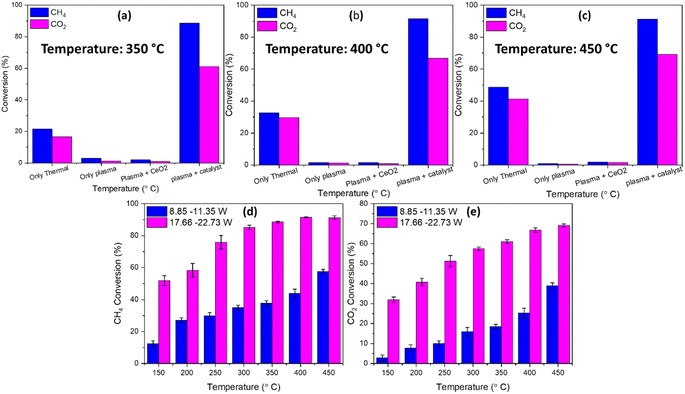 |
| | Fig. 8 Comparison plot of CH4 and CO2 conversion at (a) 350 °C, (b) 400 °C, and (c) 450 °C with thermal only, plasma only, plasma with the bare CeO2 NR support and plasma with the catalyst, and (d) CH4 and (e) CO2 conversion with two different applied plasma discharge powers (catalyst weight: ∼200 mg, flow rate: CO2: 250 sccm and CH4: 100 sccm, and frequency: 20 kHz). | |
The plasma-catalytic DRM stability of the 14 wt% Ni–1 wt% Ru/CeO2 NR catalyst was evaluated at a power of 17.66 to 22.73 W with an external temperature of 350 °C over 75 minutes. The total flow rate of 350 sccm and feed gas ratio of 0.4 (CH4:CO2 = 100:250) are maintained. As shown in Fig. 9, the CH4 and CO2 conversion percentages and carbon balance are stable with time in a plasma-assisted environment. Significant variations in the reactant conversions occurred during the first 10 minutes of reaction due to the unstable reactant concentration at the beginning of the reaction. However, the percentage difference between the two values collected 60 minutes apart was less than 4%. The 14 wt% Ni–1 wt% Ru/CeO2 NR catalyst exhibited stable conversions (CH4 ∼89% and CO2 ∼60%) within 60 min. The results show that stable reactant conversions were achieved due to the catalyst regeneration technique, low inert carbon deposition, or higher activated carbon deposition. The CH4 and CO2 conversion has slight increasing slopes, which can be attributed to plasma-catalytic synergism. A plasma-assisted environment can enhance metal dispersion over the support of the heterogeneous catalyst, start the generation of tiny metal nanoparticles, and stop nanosized catalyst particles' growth due to high temperature-induced sintering.53 Thus, a small amount of Ru addition to the catalyst raises the catalytic activity dramatically compared to an individual mono-metallic catalyst.44 This is possibly due to the greater specific surface area and qualitative metal dispersion of the smaller metal particles produced due to the catalytic plasma reaction.
 |
| | Fig. 9 Stability of the 14 wt% Ni–1 wt% Ru/CeO2 NR catalyst at 350 °C for plasma catalytic DRM (CH4 and CO2) in terms of conversion and carbon balance (catalyst weight: ∼200 mg, flow rate: CO2: 250 sccm and CH4: 100 sccm, plasma power: 17.66–22.73 W, and frequency: 20 kHz). | |
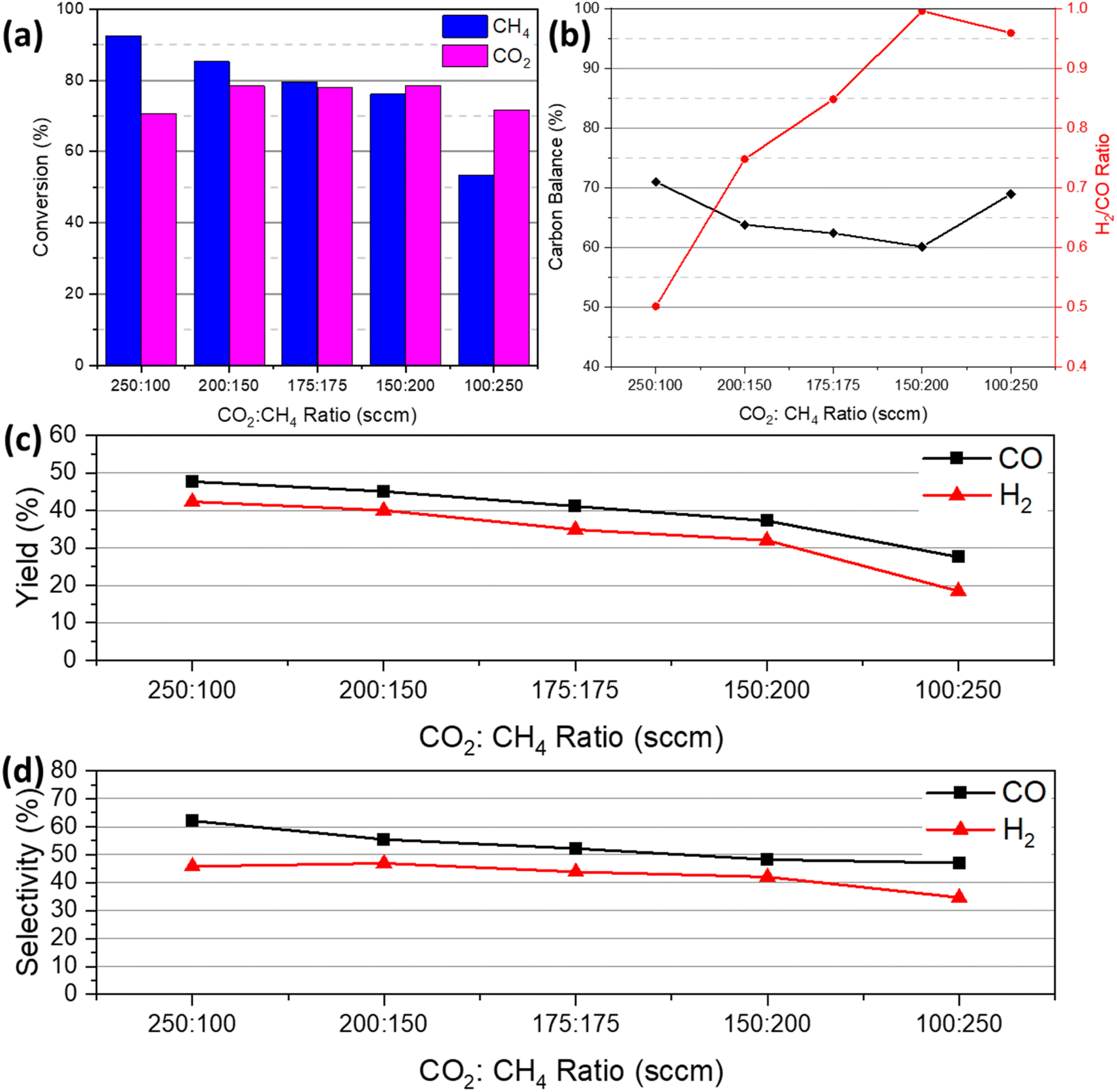
Fig. 10(a)–(d) illustrates the effect of various CO2/CH4 feed gas ratios on the reaction of plasma-assisted catalytic DRM at 450 °C with the discharge power of 17.66 to 22.73 W. Here, a total of 350 sccm of CO2 and CH4 were supplied into the reactor at various ratios: 250:100, 200:150, 175:175, 150:200, and 100:250. The literature reports that during DRM the amount of CO2 has a significant influence in CH4 conversion because metastable O (1D) molecules from CO2 breakdown react with the C–H bond, forming ethyl radicals and hydroxyl molecules.54,55 It is agreed that a lower CH4 concentration (CO2/CH4 ratio > 1) in the feed mixture will result in a higher CH4 conversion. In this study, at a CO2/CH4 ratio of 250:100, or 2.5, the CH4 conversion is 92%, while the CO2 conversion is 70%. With an increase in CH4 feed supply, the CH4 conversion fell from 92% (250:100) to 53% (100:250). As demonstrated by eqn (17) and (18), the excited oxygen O* dissociated from CO2 plays a critical role in the decomposition of CH4.
| |  | (17) |
| |  | (18) |
 |
| | Fig. 10 Plasma-catalytic DRM conversion of 14 wt% Ni–1 wt% Ru/CeO2 NR as a function of CO2:CH4 feed gas ratio at 450 °C: (a) CH4 and CO2 conversion, (b) H2/CO ratio and carbon balance, (c) CO and H2 yield and (d) selectivity (catalyst weight: ∼200 mg, total flow rate: 350 sccm, plasma power: 17.66–22.73 W, and frequency: 20 kHz). | |
These reactions suggest that the ratio of CO2 to CH4 is critical to the conversion of CH4. With varied CO2/CH4 ratios, the CO2 conversion stayed in the range of 60% and 70%. With a low CH4 feed concentration, CO generation led to a higher CH4 conversion because the formation of CO required the participation of more active CHx species. However, when the total feed flow rate of CO2 is reduced, CHx species engage in recombination rather than oxidation to produce CO.56
As the ratio of CO2 to CH4 decreased, the total conversion rate began to decline. This is because decreasing the CO2/CH4 ratio reduces the amount of oxygen in the process, which stimulates the production of hydrocarbons rather than syngas, including carbon deposition, which can be observed in Fig. 10(b). This carbon deposition can result in catalyst poisoning or deactivation. Fig. 10(b) further demonstrates that the H2/CO ratio rose as the CO2 to CH4 ratio decreased due to a greater concentration of CHx species in the reaction. Fig. 10(c) and (d) presents the CO and H2 yield and selectivity with the variation of CO2/CH4 ratios. Both yield and selectivity showed a downward trend with decreasing CO2 to CH4 feed gas ratios. The total conversion fell because of the downward ratio trend, leading to low CO and H2 yield and selectivity.
TEM images of the spent catalyst are presented in Fig. 11. It is noticeable from Fig. 11 that carbon was deposited in the form of nanotubes. This observation is consistent with the carbon balance profile (71%), illustrated in Fig. 7(h). In addition, the RAMAN characterization of the spent catalyst confirmed that the carbon is activated carbon, as presented in the ESI (Fig. S3).†
 |
| | Fig. 11 TEM images at different magnifications (a–f) of the spent 14 wt% NiO–1 wt% RuO2/CeO2 NR catalyst. | |
After the DRM reaction, each catalyst underwent a regeneration cycle with CO2 and Ar in thermal and plasma environments to recover or eliminate the carbon deposited on the catalyst's surface. Interestingly, the prepared bimetallic 14 wt% Ni–1 wt% Ru/CeO2 NR catalyst promoted a CO2-splitting reaction as shown in eqn (19) during this regeneration cycle, which increased its conversion with temperature.
This increase in conversion can be attributed to the combination of furnace temperature, the effect of NTP, and the 14 wt% Ni–1 wt% Ru/CeO2 NR catalyst. In addition, Ar acted as a highly reactive metastable species such as Ar* and Ar+, which can enhance the collision of CO2 and reactive species and promote CO2 splitting in the regeneration cycle. For instance, Jahanbakhsh et al.57 reported low-temperature CO2 splitting under an NTP environment similar to the regeneration cycle of this experiment. Fig. 12(a) and (b) depicts the variation in CO2 conversion and yield depending on the temperature in plasma and thermal only environments. With an increase in temperature from 150 °C to 450 °C under NTP catalysis, the CO2 conversion increased, reaching a highest conversion of 40%. The CO2:Ar feed gas ratio was 250:100, similar to the DBD plasma-assisted CO2 decomposition experiment reported by Ray et al.58 They concluded that the concentration of diluent gas Ar plays a crucial role in CO2 decomposition. It should be noted that at 150 °C and 200 °C under plasma-assisted catalytic regeneration, no CO2 splitting reaction was observed. Similarly, no thermal CO2 splitting was noticed up to 300 °C due to its highly endothermic nature.
 |
| | Fig. 12 Thermal and plasma-assisted CO2 splitting reaction during the catalyst regeneration cycle of 14 wt% Ni–1 wt% Ru/CeO2 NR from 150 °C to 450 °C: (a) CO2 conversion and (b) CO yield (catalyst weight: ∼200 mg, flow rate: CO2: 250 sccm and Ar: 100 sccm, power: 17.66–22.73 W, and frequency: 20 kHz). | |
4. Proposed reaction mechanism
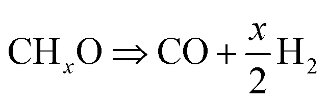
The NTP-assisted DRM reaction routes over 14 wt% Ni–1 wt% Ru/CeO2 NR can be explained based on the Langmuir–Hinshelwood mechanism. First, plasma activates CH4 and CO2 molecules which dissociate into various electronically, vibrationally and rotationally excited intermediate species such as CHx, CO2+, O, H, and CO32− which are adsorbed on the surface of the metal and/or support.59 According to the literature,60 CH4 activation is favored at metal sites, metal/support interface, or oxygen vacancies at the metal/support interface, followed by consecutive dehydrogenation. On the contrary, as an acidic species, based on the surface structure of the catalyst, CO2 adsorbs on active species in three different ways: C coordination, C–O coordination and O coordination.61 These adsorptions can be promoted by the surface basic sites of the catalyst, which contribute anionic oxygen (O2−), leading to the formation of surface covalent carbonate species (CO32−). These carbonate species interact with surface adsorbed CHx (x = 1–3) on adjacent Ni or Ru followed by production of CO and H2 (syngas).62–64 The possible reactions for the first stage are given below.
Some possible reactions are given below in Table 2 and schematically shown in Fig. 13.
Table 2 Possible reactions of plasma-assisted DRM
|
Plasma enhanced CH
4
and CO
2
dissociation
|
Catalytic CH
4
and CO
2
adsorption
|
| CH4 + e− ⇒ CH4+ + 2e− |
(R1) |
CH4 ⇒ CHx + (4 − x)H |
(R9) |
| CH4 + e− ⇒ CH3+ + H + 2e− |
(R2) |
CH4 ⇒ C + 4H |
(R10) |
| CH4 + e− ⇒ CH3 + H + e− |
(R3) |
CO2 + O2− ⇒ CO32− |
(R11) |
| CH4 + e− ⇒ CH2 + H2 + e− |
(R4) |
CO2 ⇒ CO + O |
(R12) |
| CH4 + e− ⇒ CH + H2 + H + e− |
(R5) |
|
| CO2 + e− ⇒ CO2+ + 2e− |
(R6) |
Surface desorption
|
| CO2 + e− ⇒ CO + O + e− |
(R7) |

|
(R14) |
| CO2 + e− ⇒ CO + O− |
(R8) |
H + H ⇒ H2 |
(R15) |
|
C + M–O ⇒ CO + M |
(R16) |
|
Surface reaction
|
|
M: metal |
|
| CO32− + CHx ⇒ CHxO + CO + O2− |
(R13) |
 |
| | Fig. 13 Possible reaction mechanisms of plasma-assisted DRM. | |
It is well known that the dry reforming of methane reaction favors carbon deposition or coking at higher temperatures by the following reactions.
Methane decomposition or methane cracking:
Boudouard reaction:
Under the plasma environment, carbon deposition from methane cracking is mostly activated rather than Boudouard reaction.65 This deposited carbon quite effectively reacts with oxygen radicals.66
5. Conclusion
In conclusion, plasma-assisted DRM was investigated in an atmospheric pressure DBD reactor using the 14 wt% Ni–1 wt% Ru/CeO2 NR catalyst. Plasma alone or plasma with bare support did not effectively facilitate the DRM reaction, resulting in CH4 and CO2 conversions of less than 5% over the temperature between 150 °C and 450 °C. The results revealed that the synergy between the 14 wt% Ni–1 wt% Ru/CeO2 NR catalyst and non-thermal plasma accelerated the surface reaction in the plasma-assisted DRM environment, resulting in a maximum 91% conversion of CH4 and 70% conversion of CO2, respectively, at 450 °C. Furthermore, the 14 wt% Ni–1 wt% Ru/CeO2 NR catalyst exhibited excellent stability and less coking issue, as evidenced by its sustained conversion up to 60 min without any drop, and its morphology and shape remained unchanged due to the low reaction temperature, as verified by XRD and HRTEM analyses of the spent catalyst, respectively. The Raman spectroscopy analysis of the used catalyst verified that the deposited carbon was activated carbon. Using the 14 wt% Ni–1 wt% Ru/CeO2 NR catalyst, the effect of the input feed gas ratio on plasma-assisted DRM was also studied. The findings demonstrated that an enhanced ratio of H2/CO could be achieved by increasing the CH4 feed gas percentage in the gas mixture. However, this can result in a reduced total conversion. Thus, the improved catalytic DRM performance is ascribed to the synergistic effect of non-thermal plasma and the presence of higher active sites on the CeO2 NR supported bimetallic Ni–Ru catalyst with a significant amount of surface defects including Ce3+ ions, oxygen vacancies, voids, and rough support surfaces.
Data availability
The data supporting this article have been included as part of the ESI.†
Conflicts of interest
There are no conflicts to declare.
Acknowledgements
This work is funded by the National Science Foundation (CBET-2427238 and TI-2427213).
References
- Z. Sheng, H.-H. Kim, S. Yao and T. Nozaki, Plasma-chemical promotion of catalysis for CH4 dry reforming: unveiling plasma-enabled reaction mechanisms, Phys. Chem. Chem. Phys., 2020, 22, 19349–19358 RSC.
- S. Hamzehlouia, S. A. Jaffer and J. Chaouki, Microwave heating-assisted catalytic dry reforming of methane to syngas, Sci. Rep., 2018, 8, 8940 CrossRef.
- X. Tu and J. C. Whitehead, Plasma-catalytic dry reforming of methane in an atmospheric dielectric barrier discharge: Understanding the synergistic effect at low temperature, Appl. Catal., B, 2012, 125, 439–448 CrossRef CAS.
- X. Tu and J. C. Whitehead, Plasma-catalytic dry reforming of methane in an atmospheric dielectric barrier discharge: Understanding the synergistic effect at low temperature, Appl. Catal., B, 2012, 125, 439–448 CrossRef CAS.
- R. Rajagopalan, L. Zhongqi, M. Harigovind, T. Shaon, W. Ruigang and U. Mruthunjaya, Nanoshaped CeO2 and SiO2 supported Ru catalyst for plasma catalysis chemical looping reactions, Int. J. Energy Eng., 2020, 10, 1–12 Search PubMed.
- R. V. Ranganathan, B. Jony, S. M. Fondriest, Z. Liu, R. Wang and M. Uddi, Plasma-catalysis chemical looping CH4 reforming with water splitting using ceria supported Ni based La-perovskite nano-catalyst, J. CO2 Util., 2019, 32, 11–20 CrossRef CAS.
- H. Long, Y. Xu, X. Zhang, S. Hu, S. Shang, Y. Yin and X. Dai, Ni-Co/Mg-Al catalyst derived from hydrotalcite-like compound prepared by plasma for dry reforming of methane, J. Energy Chem., 2013, 22, 733–739 CrossRef CAS.
- A. Liu, S. Praserthdam and S. Phatanasri, Investigation on the increased stability of the Ni–Co bi-metallic catalysts for the carbon dioxide reforming of methane, Catal. Today, 2020, 358, 37–44 CrossRef CAS.
- I. Rossetti, C. Biffi, C. L. Bianchi, V. Nichele, M. Signoretto, F. Menegazzo, E. Finocchio, G. Ramis and A. Di Michele, Ni/SiO2 and Ni/ZrO2 catalysts for the steam reforming of ethanol, Appl. Catal., B, 2012, 117, 384–396 CrossRef.
- G. Zeng, Q. Liu, R. Gu, L. Zhang and Y. Li, Synergy effect of MgO and ZnO in a Ni/Mg–Zn–Al catalyst during ethanol steam reforming for H2-rich gas production, Catal. Today, 2011, 178, 206–213 CrossRef CAS.
- C. Crisafulli, S. Scirè, R. Maggiore, S. Minicò and S. Galvagno, CO2 reforming of methane over Ni–Ru and Ni–Pd bimetallic catalysts, Catal. Lett., 1999, 59, 21–26 CrossRef CAS.
- A. A. M. Abahussain, A. S. Al-Fatesh, Y. B. Rajput, A. I. Osman, S. B. Alreshaidan, H. Ahmed, A. H. Fakeeha, A. S. Al-Awadi, R. A. El-Salamony and R. Kumar, Impact of Sr Addition on Zirconia-Alumina-Supported Ni Catalyst for COx-Free CH4 Production via CO2 Methanation, ACS Omega, 2024, 9, 9309–9320 CrossRef CAS.
- R. A. El-Salamony, A. S. Al-Fatesh, K. Acharya, A. A. M. Abahussain, A. Bagabas, N. S. Kumar, A. A. Ibrahim, W. U. Khan and R. Kumar, Carbon Dioxide Valorization into Methane Using Samarium Oxide-Supported Monometallic and Bimetallic Catalysts, Catalysts, 2023, 13, 113 CrossRef CAS.
- X. Duan, J. Pan, X. Yang, C. Wan, X. Lin, D. Li and L. Jiang, Nickel–cobalt bimetallic catalysts prepared from hydrotalcite-like compounds for dry reforming of methane, Int. J. Hydrogen Energy, 2022, 47, 24358–24373 CrossRef CAS.
- S. Zafarnak and M. R. Rahimpour, Co-Ni bimetallic supported on mullite as a promising catalyst for biogas dry reforming toward hydrogen production, Mol. Catal., 2023, 534, 112803 CrossRef CAS.
- R. Wang and R. Dangerfield, Seed-mediated synthesis of shape-controlled CeO2 nanocrystals, RSC Adv., 2014, 4, 3615–3620 RSC.
- R. Wang, S. I. Mutinda and M. Fang, One-pot hydrothermal synthesis and high temperature thermal stability of CexZr1−xO2 nanocrystals, RSC Adv., 2013, 3, 19508–19514 RSC.
- Z. Liu, J. Li and R. Wang, CeO2 nanorods supported M–Co bimetallic oxides (M = Fe, Ni, Cu) for catalytic CO and C3H8 oxidation, J. Colloid Interface Sci., 2020, 560, 91–102 CrossRef CAS.
- M. R. Ahasan, M. M. Hossain, Z. Barlow, X. Ding and R. Wang, Low-Temperature Plasma-Assisted Catalytic Dry Reforming of Methane over CeO2 Nanorod-Supported NiO Catalysts in a Dielectric Barrier Discharge Reactor, ACS Appl. Mater. Interfaces, 2023, 15, 44984–44995 CrossRef CAS.
-
R. V. Ranganathan, M. Monir Hossain, S. Talukdar, R. Ahasan, R. Wang and M. Uddi, Tunable Quantum Cascade Laser Absorption Spectroscopy for Plasma Assisted Oxidative Coupling of Methane to C2 Based Products, 2021 IEEE International Conference on Plasma Science (ICOPS), 2021, pp. 1–1 Search PubMed.
- M. M. Hossain, M. R. Ahasan, X. Ding and R. Wang, Coke formation pathway under various reaction conditions during the production of syngas in a dielectric barrier discharge plasma environment using CeO2 nanorods supported Ni catalysts, Chem. Eng. J., 2024, 479, 147459 CrossRef CAS.
- M. Monir Hossain, M. Robayet Ahasan and R. Wang, Influence of catalyst shape on plasma-assisted dry reforming of methane: A comparative study of Ni-CeO2 nano-cubes and nano-octahedra, Chem. Eng. J., 2024, 496, 154193 CrossRef CAS.
- M. R. Ahasan, Y. Wang and R. Wang, In situ DRIFTS and CO-TPD studies of CeO2 and SiO2 supported CuOx catalysts for CO oxidation, Mol. Catal., 2022, 518, 112085 CrossRef CAS.
- F. Wang, C. Li, X. Zhang, M. Wei, D. G. Evans and X. Duan, Catalytic behavior of supported Ru nanoparticles on the {1 0 0},{1 1 0}, and {1 1 1} facet of CeO2, J. Catal., 2015, 329, 177–186 CrossRef CAS.
- R. A. El-Salamony, K. Acharya, A. S. Al-Fatesh, A. I. Osman, S. B. Alreshaidan, N. S. Kumar, H. Ahmed and R. Kumar, Enhanced direct methanation of CO2 using Ni-based catalysts supported on ZrO2, CeO2-ZrO2, and La2O3-ZrO2: The effect of support material on the reducible NiO-interacted species and catalytic activity, Mol. Catal., 2023, 547, 113378 CrossRef CAS.
- T. Jomjaree, P. Sintuya, A. Srifa, W. Koo-amornpattana, S. Kiatphuengporn, S. Assabumrungrat, M. Sudoh, R. Watanabe, C. Fukuhara and S. Ratchahat, Catalytic performance of Ni catalysts supported on CeO2 with different morphologies for low-temperature CO2 methanation, Catal. Today, 2021, 375, 234–244 CrossRef CAS.
- L. Li, B. Jiang, D. Tang, Z. Zheng and C. Zhao, Hydrogen production from chemical looping reforming of ethanol using Ni/CeO2 nanorod oxygen carrier, Catalysts, 2018, 8, 257 CrossRef.
- M. Wang, C.-T. Au and S.-Y. Lai, H2 production from catalytic steam reforming of n-propanol over ruthenium and ruthenium-nickel bimetallic catalysts supported on ceria-alumina oxides with different ceria loadings, Int. J. Hydrogen Energy, 2015, 40, 13926–13935 CrossRef CAS.
- L. Wang, H. Liu, Y. Liu, Y. Chen and S. Yang, Influence of preparation method on performance of Ni-CeO2 catalysts for reverse water-gas shift reaction, J. Rare Earths, 2013, 31, 559–564 CrossRef CAS.
- S. Ratchahat, S. Surathitimethakul, A. Thamungkit, P. Mala, M. Sudoh, R. Watanabe, C. Fukuhara, S. S. Chen, K. C.-W. Wu and T. Charinpanitkul, Catalytic performance of Ni/CeO2 catalysts prepared from different routes for CO2 methanation, J. Taiwan Inst. Chem. Eng., 2021, 121, 184–196 CrossRef CAS.
- Y. Chen, H. Zhang, H. Ma, W. Qian, F. Jin and W. Ying, Direct conversion
of syngas to ethanol over Rh–Fe/γ-Al2O3 catalyst: Promotion effect of Li, Catal. Lett., 2018, 148, 691–698 CrossRef CAS.
- X. Li, M. Wu, Z. Lai and F. He, Studies on nickel-based catalysts for carbon dioxide reforming of methane, Appl. Catal., A, 2005, 290, 81–86 CrossRef CAS.
- H. Liu, D. Wierzbicki, R. Debek, M. Motak, T. Grzybek, P. Da Costa and M. E. Gálvez, La-promoted Ni-hydrotalcite-derived catalysts for dry reforming of methane at low temperatures, Fuel, 2016, 182, 8–16 CrossRef CAS.
- T. Sakpal and L. Lefferts, Structure-dependent activity of CeO2 supported Ru catalysts for CO2 methanation, J. Catal., 2018, 367, 171–180 CrossRef CAS.
- I. Luisetto, S. Tuti, C. Romano, M. Boaro, E. Di Bartolomeo, J. K. Kesavan, S. S. Kumar and K. Selvakumar, Dry reforming of methane over Ni supported on doped CeO2: New insight on the role of dopants for CO2 activation, J. CO2 Util., 2019, 30, 63–78 CrossRef CAS.
- I. Luisetto, S. Tuti, C. Romano, M. Boaro, E. Di Bartolomeo, J. K. Kesavan, S. S. Kumar and K. Selvakumar, Dry reforming of methane over Ni supported on doped CeO2: New insight on the role of dopants for CO2 activation, J. CO2 Util., 2019, 30, 63–78 CrossRef CAS.
- M. A. A. Aziz, A. A. Jalil, S. Wongsakulphasatch and D.-V. N. Vo, Understanding the role of surface basic sites of catalysts in CO2 activation in dry reforming of methane: a short review, Catal. Sci. Technol., 2020, 10, 35–45 RSC.
- J. Ilsemann, M. M. Murshed, T. M. Gesing, J. Kopyscinski and M. Baeumer, On the support dependency of the CO2 methanation–decoupling size and support effects, Catal. Sci. Technol., 2021, 11, 4098–4114 RSC.
- X. Li, D. Li, H. Tian, L. Zeng, Z.-J. Zhao and J. Gong, Dry reforming of methane over Ni/La2O3 nanorod catalysts with stabilized Ni nanoparticles, Appl. Catal., B, 2017, 202, 683–694 CrossRef CAS.
- L. Fan, P. F. Liu, X. Yan, L. Gu, Z. Z. Yang, H. G. Yang, S. Qiu and X. Yao, Atomically isolated nickel species anchored on graphitized carbon for efficient hydrogen evolution electrocatalysis, Nat. Commun., 2016, 7, 10667 CrossRef CAS.
- Z. Ma, S. Zhao, X. Pei, X. Xiong and B. Hu, New insights into the support morphology-dependent ammonia synthesis activity of Ru/CeO2 catalysts, Catal. Sci. Technol., 2017, 7, 191–199 RSC.
- F. Pan, X. Xiang, Z. Du, E. Sarnello, T. Li and Y. Li, Integrating photocatalysis and thermocatalysis to enable efficient CO2 reforming of methane on Pt supported CeO2 with Zn doping and atomic layer deposited MgO overcoating, Appl. Catal., B, 2020, 260, 118189 CrossRef CAS.
- F. Pan, X. Xiang, W. Deng, H. Zhao, X. Feng and Y. Li, A novel photo-thermochemical approach for enhanced carbon dioxide reforming of methane, ChemCatChem, 2018, 10, 940–945 CrossRef CAS.
- M. R. Ahasan, M. M. Hossain, X. Ding and R. Wang, Non-equilibrium plasma-assisted dry reforming of methane over shape-controlled CeO2 supported ruthenium catalysts, J. Mater. Chem. A, 2023, 11, 10993–11009 RSC.
- J. Horlyck, S. Lewis, R. Amal and J. Scott, The impact of La doping on dry reforming Ni-based catalysts loaded on FSP-alumina, Top. Catal., 2018, 61, 1842–1855 CrossRef CAS.
- A. Arman, F. Y. Hagos, A. A. Abdullah, R. Mamat, A. R. A. Aziz and C. K. Cheng, Syngas production through steam and CO2 reforming of methane over Ni-based catalyst-A Review, IOP Conf. Ser.: Mater. Sci. Eng., 2020, 42032 CAS.
- X. Zheng, S. Tan, L. Dong, S. Li and H. Chen, Plasma-assisted catalytic dry reforming of methane: Highly catalytic performance of nickel ferrite nanoparticles embedded in silica, J. Power Sources, 2015, 274, 286–294 CrossRef CAS.
- D. Ray, P. M. K. Reddy and Ch. Subrahmanyam, Ni-Mn/γ-Al2O3 assisted plasma dry reforming of methane, Catal. Today, 2018, 309, 212–218 CrossRef CAS.
- D. Zambrano, J. Soler, J. Herguido and M. Menéndez, Kinetic study of dry reforming of methane over Ni–Ce/Al2O3 catalyst with deactivation, Top. Catal., 2019, 62, 456–466 CrossRef CAS.
- M. Khajenoori, M. Rezaei and F. Meshkani, Dry reforming over CeO2-promoted Ni/MgO nano-catalyst: effect of Ni loading and CH4/CO2 molar ratio, J. Ind. Eng. Chem., 2015, 21, 717–722 CrossRef CAS.
- Istadi and N. A. S. Amin, Co-generation of synthesis gas and C2+ hydrocarbons from methane and carbon dioxide in a hybrid catalytic-plasma reactor: A review, Fuel, 2006, 85, 577–592 CrossRef CAS.
- X. Tu and J. C. Whitehead, Plasma dry reforming of methane in an atmospheric pressure AC gliding arc discharge: Co-generation of syngas and carbon nanomaterials, Int. J. Hydrogen Energy, 2014, 39, 9658–9669 CrossRef CAS.
- P. Chawdhury, K. Bhargavi, M. Selvaraj and C. Subrahmanyam, Promising catalytic activity by non-thermal plasma synthesized SBA-15-supported metal catalysts in one-step plasma-catalytic methane conversion to value-added fuels, Catal. Sci. Technol., 2020, 10, 5566–5578 RSC.
- N. A. S. Amin, Co-generation of synthesis gas and C2+ hydrocarbons from methane and carbon dioxide in a hybrid catalytic-plasma reactor: A review, Fuel, 2006, 85, 577–592 CrossRef.
- C. Liu, Y. Li, Y. Zhang, Y. Wang, J. Zou, B. Eliasson and B. Xue, Production of acetic acid directly from methane and carbon dioxide using dielectric-barrier discharges, Chem. Lett., 2001, 30, 1304–1305 CrossRef.
- N. Lu, X. Bao, N. Jiang, K. Shang, J. Li and Y. Wu, Non-thermal plasma-assisted catalytic dry reforming of methane and carbon dioxide over GC3N4-based catalyst, Top. Catal., 2017, 60, 855–868 CrossRef CAS.
- M. R. Jahanbakhsh, H. Taghvaei, O. Khalifeh, M. Ghanbari and M. R. Rahimpour, Low-temperature CO2 splitting in a noncatalytic dielectric-barrier discharge plasma: effect of operational parameters with a new strategy of experimentation, Energy Fuels, 2020, 34, 14321–14332 CrossRef CAS.
- D. Ray, R. Saha and S. Ch, DBD plasma assisted CO2 decomposition: influence of diluent gases, Catalysts, 2017, 7, 244 CrossRef.
- M. Li, Z. Sun and Y. H. Hu, Catalysts for CO2 reforming of CH4: a review, J. Mater. Chem. A, 2021, 9, 12495–12520 RSC.
- Z. Lian, S. O. Olanrele, C. Si, M. Yang and B. Li, Critical role of interfacial sites between nickel and CeO2 support in dry reforming of methane: revisit of reaction mechanism and origin of stability, J. Phys. Chem. C, 2020, 124, 5118–5124 CrossRef CAS.
- M. Li, Z. Sun and Y. H. Hu, Catalysts for CO2 reforming of CH4: A review, J. Mater. Chem. A, 2021, 9, 12495–12520 RSC.
- S. Xu, H. Chen, C. Hardacre and X. Fan, Non-thermal plasma catalysis for CO2 conversion and catalyst design for the process, J. Phys. D Appl. Phys., 2021, 54, 233001 CrossRef CAS.
- M. Li, Z. Sun and Y. H. Hu, Catalysts for CO2 reforming of CH4: A review, J. Mater. Chem. A, 2021, 9, 12495–12520 RSC.
- Z. Sheng, H.-H. Kim, S. Yao and T. Nozaki, Plasma-chemical promotion of catalysis for CH4 dry reforming: unveiling plasma-enabled reaction mechanisms, Phys. Chem. Chem. Phys., 2020, 22, 19349–19358 RSC.
-
A. S. A. S. Omran, DFT Study of Copper-Nickel (111) Catalyst for Methane Dry Reforming, MS thesis, Texas A&M University, 2019 Search PubMed.
- P. Navascués, J. Cotrino, A. R. González-Elipe and A. Gómez-Ramírez, Plasma assisted dry reforming of methane: Syngas and hydrocarbons formation mechanisms, Fuel Process. Technol., 2023, 248, 107827 CrossRef.
|
| This journal is © The Royal Society of Chemistry 2024 |
Click here to see how this site uses Cookies. View our privacy policy here. 
 Open Access Article
 This Open Access Article is licensed under a Creative Commons Attribution-Non Commercial 3.0 Unported Licence
 *b
*b