
 Open Access Article
 This Open Access Article is licensed under a Creative Commons Attribution-Non Commercial 3.0 Unported Licence
Understanding the evolution of ternary alloyed nanoparticles during reversible exsolution from double perovskite oxides†
Andrés
López-García
 a,
Alfonso J.
Carrillo
*a,
Catalina Elena
Jiménez
b,
Rosario Suarez
Anzorena
bc,
Raul
Garcia-Diez
b,
Virginia
Pérez-Dieste
d,
Ignacio J.
Villar-Garcia
de,
Ana B.
Hungría
f,
Marcus
Bär
bgh and
José M.
Serra
*a
a,
Alfonso J.
Carrillo
*a,
Catalina Elena
Jiménez
b,
Rosario Suarez
Anzorena
bc,
Raul
Garcia-Diez
b,
Virginia
Pérez-Dieste
d,
Ignacio J.
Villar-Garcia
de,
Ana B.
Hungría
f,
Marcus
Bär
bgh and
José M.
Serra
*a
aInstituto de Tecnología Química, Universitat Politècnica de València-Consejo Superior de Investigaciones Científicas, Valencia, Spain. E-mail: alcardel@itq.upv.es; jmserra@itq.upv.es
bDept. Interface Design, Helmholtz-Zentrum Berlin für Materialien und Energie GmbH (HZB), Albert-Einstein-Str.15, 12489, Berlin, Germany
cUnidad de Investigación y Desarrollo Estratégico para la Defensa (UNIDEF-CONICET-MINDEF), CITEDEF, J.B. de La Salle 4397, Buenos Aires, Argentina
dALBA Synchrotron, Carrer de la Llum 2-26, 08290 Barcelona, Spain
eFacultad de Farmacia, Departamento de Química, Urbanización Montepríncipe, Universidad CEU San Pablo, 28668 Boadilla del Monte, Madrid, Spain
fDepartamento de Ciencia de Materiales, Ingeniería Metalúrgica y Química Inorgánica, Universidad de Cádiz, Campus Río San Pedro, 11510 Puerto Real, Spain
gDept. X-ray Spectroscopy at Interfaces of Thin Films, Helmholtz-Institute Erlangen-Nürnberg for Renewable Energy (HI ERN), Albert-Einstein-Str. 15, 12489 Berlin, Germany
hDepartment of Chemistry and Pharmacy, Friedrich-Alexander-Universität Erlangen-Nürnberg (FAU), Egerlandstr. 3, 91058 Erlangen, Germany
First published on 30th July 2024
Abstract
Multicomponent nanoparticle exsolution has emerged as a promising process for obtaining highly active catalysts supported on perovskite oxides. For instance, FeCoNi alloys can be exsolved from Sr2FeCo0.2Ni0.2Mn0.1Mo0.5O6−δ, boosting the electrocatalytic properties of these electrodes. However, due to differences in cation diffusion properties, the composition of the nanoparticles is uneven and strongly affected by process conditions such as temperature. An additional key feature of exsolution is its reversibility, which could help in catalyst regeneration if poisoned. Nevertheless, there is little knowledge on the reversibility mechanisms of multicomponent exsolved alloys. For that purpose, a combination of synchrotron-based in situ X-ray Diffraction (XRD) and Near-Ambient Pressure X-ray Photoelectron Spectroscopy (NAP-XPS) was employed in this work to uncover these missing aspects of multicomponent alloyed exsolution. These techniques allowed determination of the crystallographic and surface-related phenomena occurring during reversible exsolution both to the nanoparticles and the perovskite oxide support. This enabled the identification of the exsolution onset temperature and the range at which the double perovskite to Ruddlesden–Popper transition occurred, a process that has notable implications for the electrocatalytic performance. Finally, in combination with microscopy analyses, it was possible to reveal the morphological and compositional changes that the exsolved nanoparticles experienced upon reduction–oxidation cycles. This resulted in a re-arrangement of the surface species and a variation in the composition (Fe enrichment) of the regenerated ternary alloyed exsolved nanoparticles. These results indicate that reversible exsolution might alter the catalytic properties of the exsolved nanoparticles, with profound implications in the performance of (electro)catalytic processes.
1. Introduction
Nanoparticle (NP) exsolution has emerged in the last decade as a promising metallic nanocatalyst fabrication route.1–3 It has been mainly applied to develop electrocatalysts for solid oxide fuel cells and electrolyzers, although, in the last years, its range of application has been extended to other energy-relevant processes,4 such as syngas production via methane reforming5–8 or chemical looping,9–13 CO2 hydrogenation,14 or even as gas sensors15,16 and resistive switches.17 Exsolution consists of the migration of metal transition cations that, under reducing conditions, diffuse to the surface, where they nucleate as metallic NPs. Since the particles emerge from the bulk, they remain anchored or socketed to the oxide surface, conferring high stability and robustness versus catalytic degradation phenomena such as high-temperature sintering or coking.18 In addition, exsolution offers high versatility in terms of morphological and compositional NPs tuning, which can be easily adjusted by controlling the external (processing) or intrinsic (material design) parameters.19 For instance, higher temperatures and longer exposure times lead to larger particles and decrease the NP dispersion17,20 Additionally, the NP shape can be modified by changing these parameters8 or the type of reducing gas (CO instead of H2).21 Regarding intrinsic parameters tunability, by carefully choosing the perovskite B-site cations, it is possible to obtain multi-element alloyed NPs.22 This has led to the evolution of bimetallic alloys such as FeNi23–31 CoFe,32–34 or even ternary alloyed FeCoNi NPs.6,35,36 Ternary alloy exsolution is less explored than bimetallic exsolution, although it shows high promise in terms of catalytic activity. For instance, Joo et al. reported that exsolved alloyed FeCoNi NPs presented higher CH4 conversion in dry reforming reactions compared to metallic Ni and CoNi bimetallic NPs. This improvement was ascribed to an upshift of the d-band center, which helped in the charge donation and caused a weakening of the reactants bond strengths.6 However, very few works have been devoted to a better understanding of ternary alloyed NP exsolution. In a previous work, FeCoNi alloyed NPs were exsolved from Sr2FeCo0.2Ni0.2Mn0.1Mo0.5O6−δ.20 This double perovskite material family has shown promising electrochemical properties for CO2 electrolysis, especially when combined with NP exsolution.29,34,37,38 Interestingly, by varying the exsolution temperature, NP composition, size and dispersion can be modulated. For instance, by performing the exsolution at 800 °C, the amount of Fe in the NPs is almost twice that of the exsolution at 600 °C. At these temperatures, Ni is always the element in highest concentration.20 These results showed that, by carefully controlling the exsolution processing conditions, the composition of the NPs can be tuned, which might have profound effects on reaction conversion and/or selectivity in multiple chemical processes. However, there is still little understanding of the underlying mechanism of ternary alloy exsolution and the migration/growth kinetics of the different cations involved. For that reason, in this work, we have studied ternary alloy exsolution from double perovskites using synchrotron-based in situ Near-Ambient Pressure X-ray Photoelectron Spectroscopy (NAP-XPS) and X-ray Diffraction (XRD) to shed light on both the surface properties and crystallographic evolution during exsolution. Furthermore, we have, in situ, assessed the reversibility of the exsolution process by performing reduction–oxidation cycles to gain valuable information about the regeneration of the exsolved NPs. Exsolution reversibility, also called self-regeneration, was one of the first key advantages that this process exhibited, already identified in the first reports on exsolution in literature.39–42 However, there is scarce understanding on how self-regeneration occurs during the exsolution of ternary alloys, concerning the nature and morphology of the NPs associated with the perovskite surface restructuring and crystallographic stability. Hence, in this work, we also deepen our understanding of ternary alloyed exsolved NP regeneration by considering all these aspects.2. Experimental methods
2.1. Materials fabrication
Double perovskites were fabricated following the protocol described in a previous work.20 Briefly, powders of Sr2FeCo0.2Ni0.2Mn0.1Mo0.5O6−δ were synthesized by a modified Pechini method. Metal precursors, Sr(NO3)2 (99%, Aldrich), Fe(NO3)3·9H2O (98%, Aldrich), Co(NO3)2·6H2O (99%, Aldrich), Ni(NO3)2·6H2O (98.5%, Aldrich), Mn(NO3)2·4H2O (98%, Aldrich) and H24Mo7O24N6·4H2O (99%, Aldrich) were dissolved in distilled water, together with citric acid (CA, 99%, Alfa Aesar) using a molar ratio metal precursor![[thin space (1/6-em)]](https://www.rsc.org/images/entities/char_2009.gif) :CA of 1:1.5, under constant stirring at 60 °C. Once dissolution was completed, ethylene glycol (EG, 99%, Aldrich-Merck) was added as a complexing agent (CA:EG ratio of 2/3 wt%) and the temperature was raised to 80 °C for faster water elimination for 2 hours. After most of the water was evaporated, the solution was transferred to a drying oven and heated to 220 °C overnight for gelification, followed by the calcination of the formed gel. The solid obtained was grounded in agate mortar to fine powders, then sintered at 1100 °C in air for 12 hours. Ex situ exsolution treatments were carried out in a horizontal tubular furnace under 5% H2/Ar flow and at the temperature conditions detailed in the following sections.
:CA of 1:1.5, under constant stirring at 60 °C. Once dissolution was completed, ethylene glycol (EG, 99%, Aldrich-Merck) was added as a complexing agent (CA:EG ratio of 2/3 wt%) and the temperature was raised to 80 °C for faster water elimination for 2 hours. After most of the water was evaporated, the solution was transferred to a drying oven and heated to 220 °C overnight for gelification, followed by the calcination of the formed gel. The solid obtained was grounded in agate mortar to fine powders, then sintered at 1100 °C in air for 12 hours. Ex situ exsolution treatments were carried out in a horizontal tubular furnace under 5% H2/Ar flow and at the temperature conditions detailed in the following sections.
2.2. Morphological characterization
High-Resolution Field Emission Scanning Electron Microscopy (HRFESEM) characterization was done with a GeminiSEM 500 from Zeiss. High-Resolution Scanning Transmission Electron Microscopy, HRSTEM, analyses were performed at 200 kV on a double aberration-corrected FEI Titan3 Themis 60-300 microscope. The instrument is equipped with a monochromatic, high-brightness XFEG source and a high-sensitivity Super-X-EDS system composed of 4 window-less SDD detectors symmetrically arranged around the sample and the objective lens pole pieces. The Energy Dispersive X-ray Spectroscopy (XEDS) maps were acquired using a beam current of 50 pA, convergence angle of 19 mrad and 20 keV. Oxidized and re-exsolved NPs were analyzed with a JEM 2100F at 200 kV. Also, XEDS was performed to study compositions of exsolved NPs with an XEDS X-Max 80 Oxford Instruments.2.3. In situ X-ray diffraction
In situ X-ray diffraction (XRD) was performed at the BL04-MSPD beamline located at the ALBA synchrotron. Pristine (fine powder) samples were placed in the central zone of quartz capillaries of 1/8 inch outer diameter. The capillaries were connected to the gas delivery system, which consisted of a set of mass flow controllers delivering either 5% H2/Ar or synthetic air. The samples were heated with a FMB Oxford hot air blower (see Fig. S1b† for more details). A PSD Mythen detector was used, using a wavelength of 0.41345 Å. Scans covered a 2θ range of 0–35°. In a typical run (see Fig. S3†), in situ XRD was performed while heating up to the desired temperature in 5% H2/Ar. Then, after an isothermal period of 4 h in the same reducing conditions, the gas was switched to synthetic air for 2 h. Finally, a second reducing isothermal treatment of 2 h was performed by changing back to 5% H2/Ar to check the exsolution regeneration. Exsolution reversibility was evaluated at two different temperatures, 600 and 800 °C. It should be noted that the exsolutions were performed under dry conditions in order to replicate our previous work,20 thus, the effect pO2 might suffer variations over the course of the experiment. This could be fixed by performing the exsolutions with controlled pH2O, however, it should be kept in mind that working under humidified conditions could also affect the exsolution process by itself.2.4. In situ near ambient pressure XPS
Near Ambient Pressure X-ray Photoelectron Spectroscopy (NAP-XPS) was performed at the BL-24 CIRCE beamline located at the ALBA synchrotron.43 This beamline provides an energy resolution of E/ΔE ∼ 8000. Porous pellets of the perovskite oxide were held by a 0.12 mm thick Pt foil onto the sample holder. An IR laser (up to 150 W power) was used for sample heating (Fig. S1a†). The in situ NAP-XPS measurements were performed in several stages. First, a cleaning step was performed by heating the sample up to 600 °C in a pure O2 atmosphere (0.2 mbar) to remove carbonaceous species from the surface. At this point, NAP-XPS was performed to record data in the pristine state. After the cleaning period, the temperature was lowered to 300 °C, from where the sample was slowly heated up to 600 °C in a pure H2 atmosphere (0.2 mbar). The formation of metallic species was first monitored by following changes in the valence band (VB) and in the Ni 2p3/2 core level spectrum. Once the VB showed changes indicative of a metallic phase (i.e., appearance of spectral intensity at the Fermi edge at 0 eV binding energy, BE), Ni 2p3/2, Co 2p3/2, and Fe 2p3/2 core level spectra were measured in intervals of 25 °C until reaching ∼600 °C (max. temperature allowed by the set-up). After reaching this temperature, a complete survey spectrum of all the elements contained in the perovskite was collected. Finally, the gas atmosphere was switched back to pure O2 (0.2 mbar) to analyze the reversibility of the exsolution process. For the pristine, reduced and re-oxidized states, several sample depths were analyzed by tuning the photon energy such that the photoemission lines of interest were collected at different kinetic energies. Mo 3d, O 1s, and Sr 3d spectra were fitted with CasaXPS, using a Shirley background and a Gaussian–Lorentzian (30) line shape. The thick Pt foil that held the pellet was used for energy calibration, setting the Pt 4f7/2 to a BE of 71.1 eV.3. Results
3.1. Ternary alloyed nanoparticle exsolution formation
![[3 with combining macron]](https://www.rsc.org/images/entities/char_0033_0304.gif) m). A very minor presence of NiO impurities were detected, which was not inferred in our previous work when using lab-based XRD.20 Despite this, it was possible to in situ monitor the decomposition of NiO, benefitting from the high-resolution synchrotron-based equipment. During this first set of experiments, the Sr2FeCo0.2Ni0.2Mn0.1Mo0.5O6−δ sample powders (contained in capillaries) were subjected to a heating stage up to 820 °C under a constant flow of 5% H2/Ar atmosphere while in situ monitoring changes occurring during the reduction process via XRD. Here, we will focus on two main diffraction regions. First, the one around 8.52° (λ = 0.41345 Å), which corresponds to the double perovskite's (2 2 0) main reflection. Secondly, the region around 11.4–11.6°, where the reflections ascribed to the main signals of metallic phases are expected to appear. Therefore, a double objective is pursued: to evaluate the possible perovskite transformation under high-temperature reduction conditions and explore the formation of the multi-metallic exsolved NPs.
m). A very minor presence of NiO impurities were detected, which was not inferred in our previous work when using lab-based XRD.20 Despite this, it was possible to in situ monitor the decomposition of NiO, benefitting from the high-resolution synchrotron-based equipment. During this first set of experiments, the Sr2FeCo0.2Ni0.2Mn0.1Mo0.5O6−δ sample powders (contained in capillaries) were subjected to a heating stage up to 820 °C under a constant flow of 5% H2/Ar atmosphere while in situ monitoring changes occurring during the reduction process via XRD. Here, we will focus on two main diffraction regions. First, the one around 8.52° (λ = 0.41345 Å), which corresponds to the double perovskite's (2 2 0) main reflection. Secondly, the region around 11.4–11.6°, where the reflections ascribed to the main signals of metallic phases are expected to appear. Therefore, a double objective is pursued: to evaluate the possible perovskite transformation under high-temperature reduction conditions and explore the formation of the multi-metallic exsolved NPs.
Fig. 1a shows the changes affecting the (2 2 0) reflection of the double perovskite under constant heating in a 5% H2/Ar atmosphere in the 400–820 °C region. Upon heating, a shift to lower 2θ values can be observed, which is ascribed to a lattice expansion of the double perovskite phase. During the reduction treatment that leads to the exsolution process, H2 reacts with the perovskite lattice oxygen, creating oxygen vacancies in the perovskite. In addition, reducible cations in the bulk phase will lower its oxidation state, increasing their ionic radii. These two chemical processes cause the lattice expansion. During this initial heating stage, only a very minor emergence of a Ruddlesden–Popper (RP) phase was inferred (Sr3FeMoO7, I4/mmm tetragonal structure). This can be observed in Fig. 1c, where a minor contribution of an RP phase at around 8.31° appears at temperatures above 780 °C. In our previous work, we confirmed the formation of this RP phase and identified it as one of the reasons for the lower performance of the electrodes exsolved at 800 °C versus the electrodes exsolved at 600 °C, since the former exhibited a higher tendency to form SrCO3 species under CO2 electrolysis conditions.20
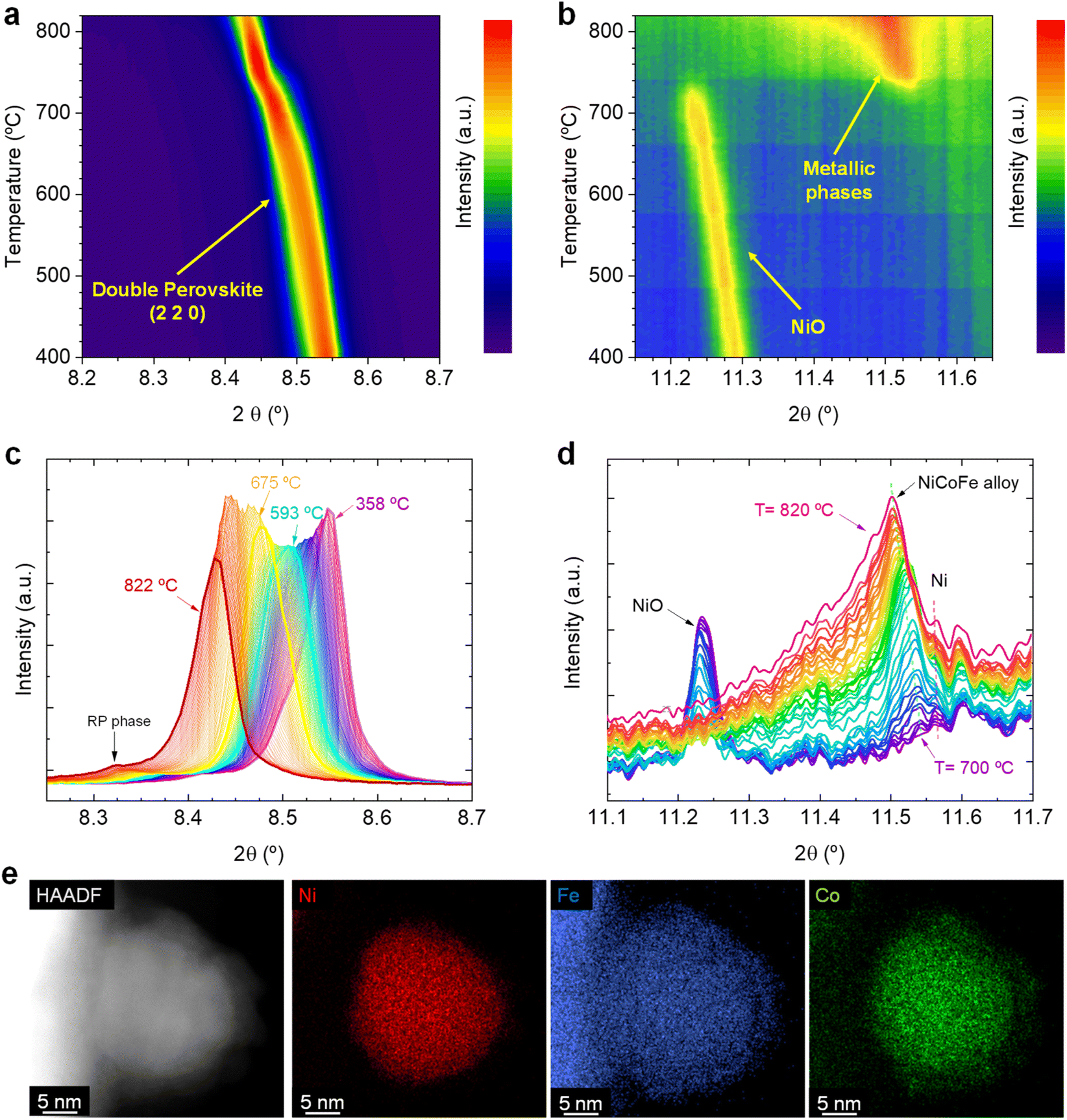 | ||
| Fig. 1 Contour maps depicting the X-ray diffraction changes occurring in the (a) 8.2–8.7° and (b) 11.1–11.7° 2θ regions, respectively, when heating up the Sr2FeCo0.2Ni0.2Mn0.1Mo0.5O6−δ sample up to 800 °C, under 5% H2/Ar flow. X-ray diffractograms of the (c) 8.2–8.7° and (d) 11.1–11.7° 2θ regions depicting the changes in the main perovskite reflection and the metallic phases, respectively. (e) High-Angle Annular Dark-Field from Scanning Transmission Electron Microscope (HAADF-STEM) image and XEDS maps of a ternary alloyed exsolved NP with a cationic ratio Co0.28Fe0.18Ni0.54 from Sr2FeCo0.2Ni0.2Mn0.1Mo0.5O6−δ. These images were taken ex situ after a treatment of 4 hours exsolution at 800 °C in a 5% H2/Ar atmosphere. | ||
Fig. 1b shows the crystallographic changes occurring in the 11.2–11.6° region, in which metallic reflections are expected. Starting at 400 °C, the reflections associated with NiO impurities are observed at 11.3°. During the temperature increase to 715 °C, this signal slightly shifts to lower 2θ values due to thermal lattice expansion. At this temperature, the NiO reflection vanishes, and a peak around 11.55° emerges, indicating the formation of a metallic phase. With increasing temperature further (715–820 °C range), the signal broadens asymmetrically and the main peak shifts to 11.5°. For a clearer view, Fig. 1d shows the transition in this temperature region (from 700 to 820 °C). The progressive disappearance of the NiO is expected to lead to the formation of metallic Ni, in agreement with our XRD data. The metallic Ni formation from NiO was already observed via HRFESEM in our previous works, where polygonal cavities around certain particles could be seen, typically formed after NiO reduction.20 This process slightly interferes with the detection of the exsolved metallic phase since Ni and the possibly forming ternary alloy FeCoNi would show diffraction peaks at almost identical 2θ angles. Unfortunately, there are few references for crystallographic information on FeCoNi, as it is Co0.027Fe0.283Ni0.689, the closest composition to the expected exsolved ternary alloys. This composition (Fmm space group) presents its most intense reflection at 11.58° (COD 9000088), whereas, for metallic Ni, it is around 11.59° (ICSD 250535, data at room temperature). Therefore, two distinct reflections might appear in a narrow 2θ range. This can be better observed in Fig. S2b,† which shows the 11.0–12.6° region, depicting the appearance of two distinct reflections: one at 11.60° (ascribed to Ni) and another at 11.54°, which suggests the formation of the exsolved metallic alloy. Here, it should be noted that ex situ STEM-XEDS analyses performed after a reduction treatment at 800 °C for 4 h (Fig. 1e) show the presence of ternary-alloyed NPs mainly composed of Ni and, to a lesser extent, Co and Fe.20 This might alter the positions at which the ternary alloy appears if compared to the database pattern, which slightly differs in composition. By increasing the temperature, the exsolved alloy peak shifts to 11.5°, whereas the Ni metallic peak remains almost unaltered at the same position (Fig. 1d). This shift may, hence, be attributed to a change in the composition of the exsolved metal alloy. However, the influence of thermal expansion cannot be discarded. The formation of Ni-rich nuclei may occur in the early stages of the exsolution process, facilitating the incorporation of either Co and/or Fe afterwards. This shall be especially considered for the case of Fe since in this family of Sr–Fe–Mo-based perovskites, Fe exsolution has been scarcely reported and usually requires a more reducible cation (for instance, Ni or Co) to allow the formation of Fe-based bimetallic alloys. This was observed in Carrillo and Serra's work, in which a double perovskite with just Fe and Mo on the B-site does not lead to the creation of exsolved NPs, whereas a partial substitution with Ni leads to a remarkable bimetallic exsolution under the same conditions.5 It is important to highlight that these Ni-rich nuclei come from the Ni exsolution, and not from the Ni0 produced due to the reduction of NiO impurities. This fact lies on our previous studies with these materials, where the presence of NiO impurities acted detrimentally to the nucleation during exsolution. A-site deficient materials exhibited lower NP populations with increasing NiO amounts. Therefore, we could rule out that the Ni0 coming from NiO reduction is acting as preferential nucleation sites.20
Another exciting feature is observed when comparing Fig. 1a and b. The formation of the exsolved metallic particles occurs at the same temperature (between 715 and 720 °C) at which an inflection is observed in the double perovskite main reflection, together with a peak narrowing (Fig. 1a). This might be a combination of crystal cell expansion caused by the reduction of the lattice cations during the exsolution process and peak narrowing due to the disappearance of some secondary phase at around 8.5° (Fig. 1c, 358 °C diffractogram) that causes an asymmetrical peak shape. In addition, the asymmetrical peak broadening visible at temperatures above 760 °C (Fig. 1b) is ascribed to the appearance of the (0 0 10) reflection of the RP phase previously mentioned. For a better view of the evolution affecting the crystal phases during the heating, diffractograms including the whole measured 2θ range are depicted in Fig. S2c.†
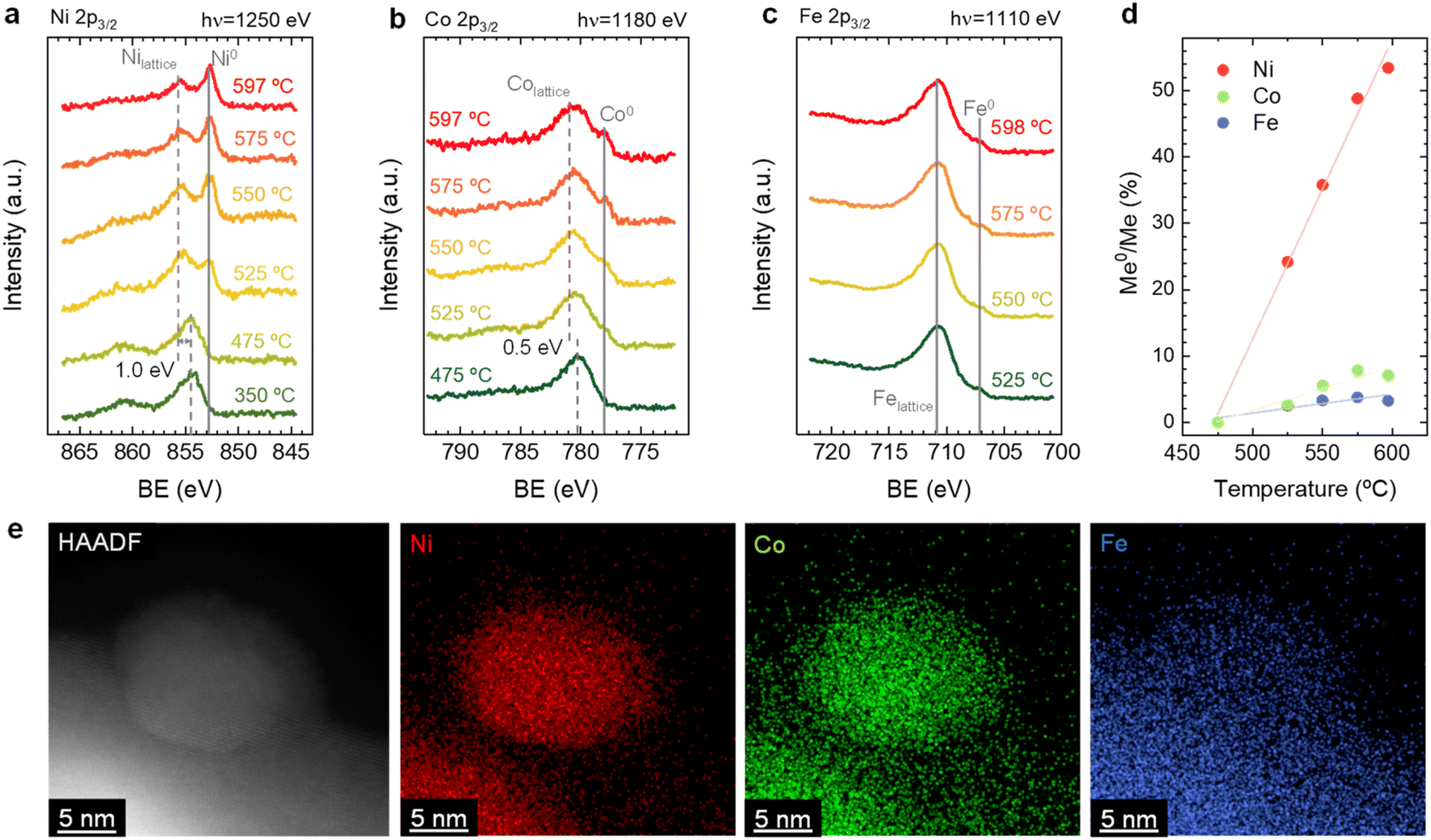 | ||
| Fig. 2 Evolution of NAP-XPS (a) Ni 2p3/2, (b) Co 2p3/2, and (c) Fe 2p3/2 spectra upon temperature-programed reduction treatment. The used photon energies (to result in a similar electron kinetic energy of 400 eV) are indicated in the panels. A constant offset for better clarity is added to the spectra. (d) Variation of the metal to oxide content (Me0/Me) versus temperature for each element. (e) HAADF-STEM image and XEDS maps of a ternary alloyed exsolved NP with cationic ratio Co0.28Fe0.1Ni0.63 from Sr2FeCo0.2Ni0.2Mn0.1Mo0.5O6−δ. These images were taken ex situ after a treatment of 4 hours exsolution at 600 °C in a 5% H2/Ar atmosphere. | ||
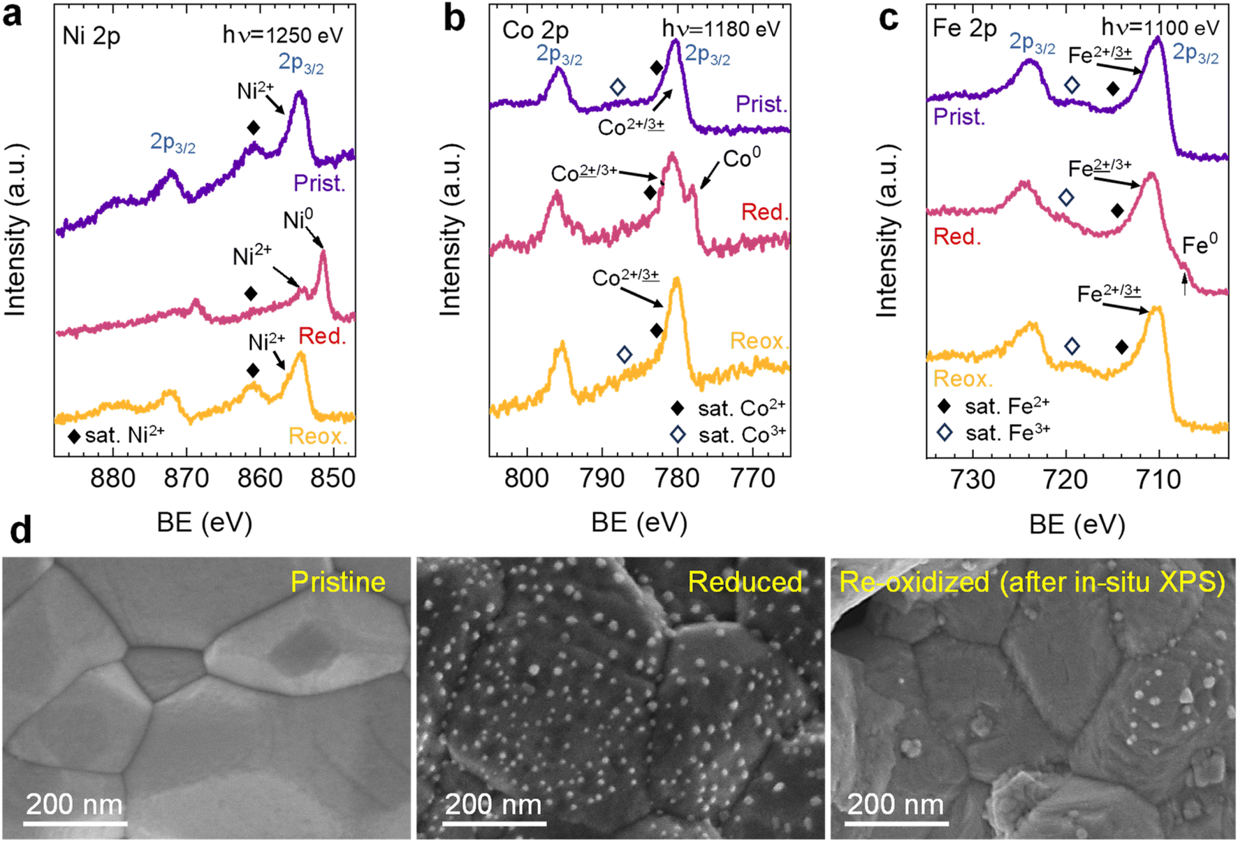 | ||
| Fig. 3 NAP-XPS spectra of (a) Ni 2p, (b) Co 2p, and (c) Fe 2p acquired in situ at 600 °C in pristine (“Prist.”, 0.2 mbar O2), reduced (“Red.”, 0.2 mbar H2) and re-oxidized (“Reox.”, 0.2 mbar O2) conditions. The used photon energies (to result in a similar electron kinetic energy of ∼400 eV) are indicated in the panels. A constant offset for better clarity is added to the spectra. (d) HRFESEM micrographs of Sr2FeCo0.2Ni0.2Mn0.1Mo0.5O6−δ at pristine, reduced, and re-oxidized stages. The re-oxidized micrograph of the sample was taken after NAP-XPS in situ experiments. | ||
By combining the obtained results from both the in situ XRD and NAP-XPS experiments, it is possible to unveil some mechanistic insights related to the exsolution of ternary alloys from Sr2FeCo0.2Ni0.2Mn0.1Mo0.5O6−δ double perovskites. First, from the in situ XRD, we could rule out the formation of isolated monometallic exsolved NPs of Ni, Co, or Fe during exsolution in this system. This mechanism was introduced by Kwon et al. to explain the formation of CoNi alloys.50 Using in situ XRD, the authors observed the formation of Co0 and Ni0, which, upon heating, transformed into the metallic CoNi alloy. Additionally, DFT calculations performed by the authors established that the thermodynamically favored path consists of the co-segregation of isolated metallic cations and later aggregation on the surface, leading to the alloy formation. The less favored path might be the alloy formation in bulk followed by its exsolution. In this work, we observed the presence of metallic Ni, but resulting from the thermal reduction of NiO impurities. However, Fe and Co isolated metallic species were not detected even at high temperatures of 800 °C (Fig. 1). In addition, no single-metal NP could be found during XEDS analyses, nor could it have a composition different from the explained FeCoNi alloy. Thus, the mechanism proposed by Kwon et al., even if thermodynamically more favorable than other scenarios, does not apply to our case. Alternatively, the case in which one of the exsolvable species acts as a nucleation site for the rest of the cations shall be considered. This hypothesis is based on the fact that, in this kind of double perovskites, exsolution has been scarcely observed from the undoped systems, e.g., Fe exsolution from Sr2Fe1.5Mo0.5O6−δ,5 and only when Ni and/or Co partially replaced Fe, it was possible to observe alloy exsolution.29,34,51,52 Lv et al. used in situ STEM-XEDS for analyzing the formation of bimetallic CoFe alloys in La0.4Sr0.6Co0.2Fe0.7Mo0.1O3−δ.53 They observed that, at 600 °C, the NPs were only formed by Co, whereas at 700 °C, the composition indicated FeCo alloy exsolution. Based on DFT results, Lv et al. argued that Fe exsolution is more energetically favored after Co vacancies formation. The authors' TEM analyses did not show the formation of isolated Fe NPs,53 which might also indicate a distinct mechanism than the one proposed by Kwon et al.50 It should be noted that both Kwon's and Lv's works studied different perovskite materials than analyzed in our work, which implies that differences in the materials properties, e.g., ionic diffusion, energy of vacancy formation (both for oxygen and cationic vacancies), foreseeably lead to variations in the exsolution mechanism. A good example is that isolated Fe exsolution has been reported in other perovskite systems, such as La0.6Sr0.4FeO3 (LSF).54–56 Interestingly, in similar Co-doped ferrites, DFT calculations by Lv et al. showed segregation energies for Co and Fe in similar value ranges, around 0.5 eV. However, incorporation of Mo in the B-site increased these values to 0.7 and 1.79 eV, respectively.53 This result suggested a detrimental effect of Mo presence in Fe exsolution. In the same work, the authors also found that the formation of Co vacancies led to a decrease in the Fe segregation energy from 1.79 to 0.97 eV, revealing the importance of cationic vacancies in facilitating Fe exsolution. The same effect was also found by Lv et al. for Sr2Fe1.4Ru0.1Mo0.5O6−δ. In this system, DFT calculations resulted in a Fe segregation energy of 0.97 eV, which decreased to 0.65 and 0.37 eV when considering the presence of oxygen vacancies and Ru exsolution, respectively.57 Therefore, in this particular case, and based on the faster migration kinetics and exsolution behavior observed for Ni (Fig. 2d), it might be facilitating the exsolution of the other two metallic species (Co, Fe) acting as nucleation preferential sites and/or decreasing the segregation energies of Co and/or Fe. In addition, this fact also confirms that none of the hypotheses of Kwon et al. entirely satisfies the observed phenomena here.
3.2. Understanding exsolution redox reversibility
After observing the exsolution reversibility based on NAP-XPS data of Ni, Co, and Fe, the focus will now be on the analysis of the non-exsolvable lattice elements to understand the overall changes affecting the perovskite surface chemistry under the reducing (exsolution)/oxidizing treatments. Fig. 4 depicts the NAP-XPS spectra of the Mn 2p, O 1s, Mo 3d, and Sr 3d core levels acquired in situ at 600 °C. Beginning with Fig. 4a, which shows the Mn 2p photoemission lines: the Mn 2p3/2 spectra of the pristine and re-oxidized sample exhibit a major contribution at around 641 eV, ascribed to Mn3+. Another minor contribution can be observed at higher BE of around 643 eV, attributed to Mn4+.58,59 After reduction, there is a shift to lower BE due to the reduction of Mn3/4+ to Mn2+.46 However, the significant spectral width of Mn 2p3/2 and Mn 2p1/2 peaks suggests that manganese in the reduced state might in fact be a superposition of spectral features related to 2+ and 3+ oxidation states. Additionally, in Fig. S5a,† the Mn spectra acquired with a lower electron kinetic energy (150 eV) can be seen, revealing a similar structure profile along the host perovskite.
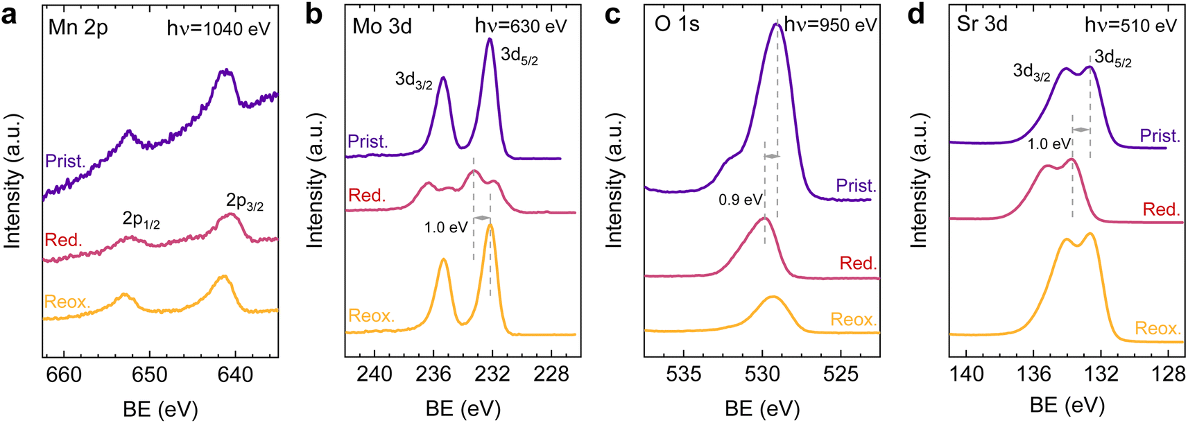 | ||
| Fig. 4 NAP-XPS spectra of (a) Mn 2p, (b) Mo 3d, (c) O 1s, and (d) Sr 3d acquired in situ at 600 °C in pristine (“Prist.”, 0.2 mbar O2), reduced (“Red.”, 0.2 mbar H2) and re-oxidized (“Reox.”, 0.2 mbar O2) conditions. The used photon energies (to result in a similar electron kinetic energy of ∼400 eV) are indicated in the panels. A constant offset for better clarity is added to the spectra. | ||
Fig. 4b exhibits the Mo 3d core level spectra. In the pristine sample state, the NAP-XPS data reveals that Mo is in the 6+ oxidation state, consistent with the Mo 3d5/2 peak at ca. 232 eV.60 Upon reduction, this peak shifts 1.0 eV to higher BE, ascribed to the change in oxygen partial pressure (this is also clearly observed for O 1s and Sr 3d spectra).30 In addition, in the reduced form, the intensity decreases, and a second peak appears, which is related to Mo5+,60 as Mo is partially reduced under exsolution treatment conditions. To quantify the amount of Mo6+ that gets reduced to Mo5+, all the Mo 3d spectra were fitted following the work of Spevack and McIntyre.60 Fig. S6† shows all the fitted spectra for the pristine, reduced and re-oxidized sample states using three photon energies: 380, 630 and 930 eV. These photon energies were applied to result in 150, 400 and 700 eV electron kinetic energies, respectively. Nevertheless, those are approximate values, and the exact electron kinetic energies employed might be shifted in order to avoid Auger signal overlaying. In the pristine and re-oxidized sample state, only Mo6+ is present at the surface of the double perovskite. In the reduced sample state and for the three photon energies assessed, Mo5+ 3d5/2 and 3d3/2 peaks appear at 231.9 and 235.05 eV, respectively. The Mo5+/Mototal ratio was 0.48, 0.49, and 0.48 when acquired with 380, 630 and 930 eV photon energies, respectively. This indicates that, during the exsolution process that took place under these conditions (600 °C, 0.2 mbar H2), almost half the Mo6+ surface cations were reduced to Mo5+, regardless of the sampling depth applied. In addition, upon re-oxidation, a full return to the 6+ oxidation state is observed. Despite during 600 °C XRD experiments (1 bar 5% H2/Ar) no RP phase formation was observed, the H2 pressure used in NAP-XPS can be determinant to ease the partial phase transformation into RP. So then, that remarkable formation of Mo5+ might be attributed to the crystallographic phase transformation from double perovskite (with a generic formula Sr2Fe1.5M0.5O6) into a Ruddlesden–Popper phase (Sr3FeMoO7), as previously discussed.20,34,52 In Sr3FeMoO7, Fe is in +3 state and Mo in +5 oxidation states, which matches well with the extracted results from the NAP-XPS data. Therefore, under the conditions used for these NAP-XPS experiments, it can be assumed that a significant part of the double perovskite is being transformed at the surface into the RP phase.
O 1s and Sr 3d spectra are depicted in Fig. 4c and d, respectively. Focusing on the O 1s spectra, it shall be noted that the pristine peak intensity is much higher than in the reduced and re-oxidized sample states. In addition, it presents a higher contribution of adsorbed species, as inferred from the signal at 532 eV.30 To better understand the changes that O 1s experienced during the redox experiments, a thorough analysis of the NAP-XPS spectra of all the states (pristine, reduced and re-oxidized) acquired with three different photon energies (705, 950 and 1250 eV to result in ca. 150, 400 and 700 eV electron kinetic energies, respectively) is depicted in Fig. 5. The O 1s XPS spectra were fitted considering three distinct components. The one at 532 eV is attributed to adsorbed oxygen species at the surface or secondary phases.61 The peak at around 530 eV is also considered a surface component, and it is ascribed to oxygen in the surface outer-surface layer of the perovskite structure layer.61 Finally, the low energy component at around 528 eV is attributed to oxygen in the perovskite lattice. As a general trend, the O 1s spectra component deconvolution (Fig. 5) suggests that increasing the kinetic energy (so then, higher IMFP) shows an increase of the lattice component with respect to the surface species. This is especially evident for the pristine sample state. In the case of the reduced sample state, the spectra were deconvoluted just with the lattice and surface outer-surface layer oxygen since adsorbed species were not inferred. These chemisorbed oxygen species are usually (OH)ads−, Oads−, and/or Oads2−.30 Upon re-oxidation under an oxygen atmosphere, some of these species regenerate (a signal at around 532 eV shows up again). However, in the re-oxidation state, these peaks have less intensity than in the pristine state, suggesting that some of the adsorbed species do not regenerate. This might be the case for (OH)ads−, which could be present in the pristine sample state but does not regenerate in the dry oxygen conditions employed in the re-oxidation step. Notably, in the pristine sample state, adsorbed carbonaceous species were removed from the surface thanks to the pre-heating stage performed at the beginning of the in situ experiment (Fig. S3†). This is confirmed in Fig. S7,† which shows the C 1s + Sr 3p core level regions for the pristine sample state. There, only the spin–orbit doublet associated with Sr 3p is observed, whereas no peak at around 284.8 eV that could be associated with carbon-containing species was detected.
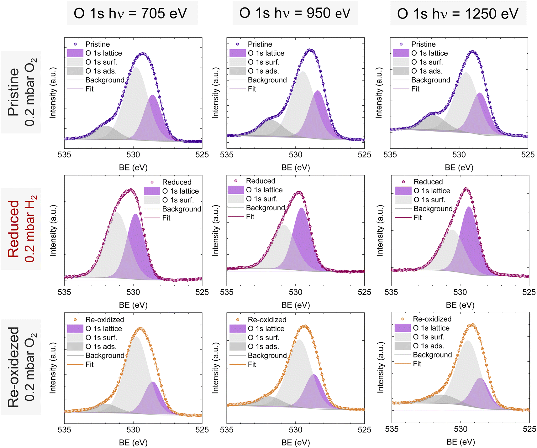 | ||
| Fig. 5 NAP-XPS spectra of O 1s in the pristine (0.2 mbar O2), reduced (0.2 mbar H2), and re-oxidized (0.2 mbar O2) sample states recorded using three photon energies: 705, 950 and 1250 eV. | ||
To understand the variations in the O 1s spectra at each sample state and representing different sampling depths, the surface/bulk ratio was quantified based on the fitted data and plotted against the IMFP in Fig. 7a. As expected, for the reduced sample state we find the lowest surface/bulk ratio at every considered IMFP (ca. 0.5, 1.0, and 1.5 nm). This fact is related to the formation of oxygen vacancies  during the reducing process. Interestingly, upon re-oxidation, the surface/bulk ratio is increased compared to the pristine sample state, indicating an oxygen enrichment affecting every layer after re-oxidation. The calculated values (ca. 3.0–3.5 nm) are significantly higher than for other studied perovskites, such as SrTi1−xFexO3.30
Lastly, Fig. 6 shows the fitted NAP-XPS spectra of the Sr 3d core level for all the studied sample states recorded using 260, 510, and 810 eV photon energies (to result in ca. 150, 400, and 700 eV electron kinetic energies, respectively). The Sr 3d spectra were, in all cases, fitted considering two spin–orbit doublet components: one at lower BE (Sr 3d5/2 at ∼132.2 eV) ascribed to Sr in the perovskite lattice and the high energy doublet (Sr 3d5/2 at ∼133.5 eV) attributed to Sr in the surface.61 In this case, the Sr surface species is most likely SrO or Sr(OH)2 (ref. 30 and 48) since, as previously mentioned, carbon compounds (such as SrCO3), were not observed. It is worth mentioning that the width of the surface fit components is broader than the bulk ones (Fig. 6). This has been previously reported for Sr 3d and it is ascribed to the larger disorder (i.e., different bond lengths and/or angles) affecting the surface components when compared to the bulk.30 A similar phenomenon was observed for O 1s (Fig. 5). The surface/bulk ratio for the Sr species was quantified based on the fitted NAP-XPS spectra and plotted in Fig. 7b. As a general trend, the surface/bulk ratio decreases with increasing IMFP for every sample state (pristine, reduced, and re-oxidized). For IMFPs of ∼0.5 and ∼1.0 nm, the surface/bulk ratio is above that in the pristine sample state, suggesting a Sr surface enrichment affecting the outer-surface layer, commonly observed in perovskite oxides.30,48,61,62 Increasing the IMFP up to ∼1.5 nm decreases the surface/bulk ratio, indicating a less-pronounced Sr enrichment in inner lattice layers. Interestingly, at every considered IMFP, the pristine sample state exhibits the highest surface/bulk ratio, followed by the re-oxidized and, lastly, the reduced sample state. This Sr enrichment for the pristine sample state (for ca. 0.6 and 1.0 nm IMPF) might be due to a presence of segregated SrO.30 This phase is most likely amorphous since no evidence of its presence could be detected in the XRD data (see Fig. 1). These SrO segregations might impact detrimentally the electrocatalytic performance of the electrodes.20 Moreover, recently, Riedl et al. highlighted the possible interaction of these Sr segregations with trace amounts of sulfur species, even in high purity gases, which negatively affected to the polarization resistance of the studied cells.63 Upon reduction, this SrO segregation disappears, thus lowering the surface/bulk ratio. After re-oxidation, the Sr surface-to-bulk ratio slightly increases compared to reduced sample state, but never reaches the pristine sample state values. Therefore, the SrO segregated phase presumably does not reform during re-exsolution. It is worth mentioning that both, O 1s and Sr 3d surface/bulk ratios studied suggest a reorganization of the superficial layers of the host double perovskite, which might affect exsolution process during subsequent reductions.
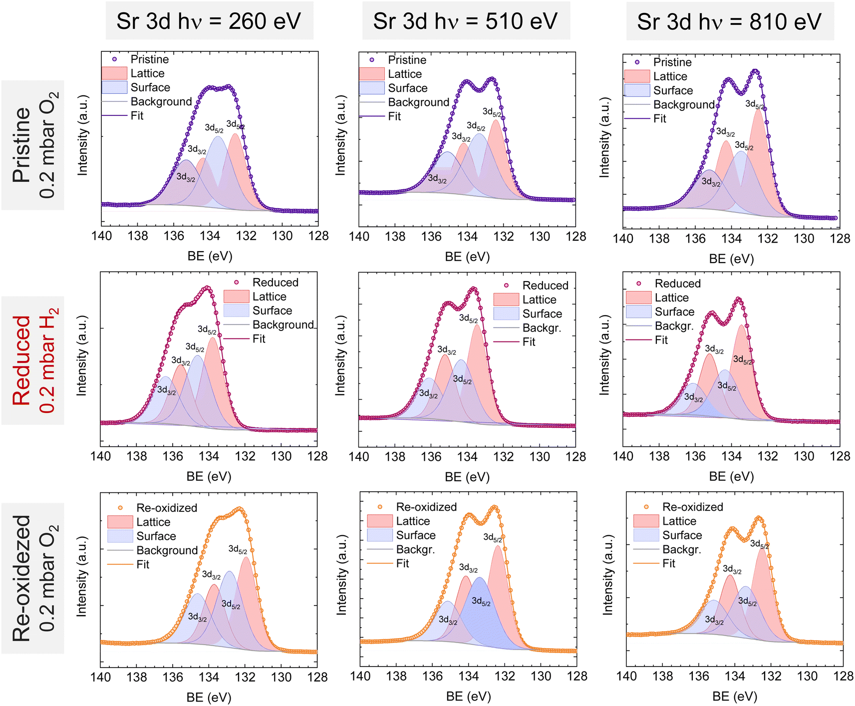 | ||
| Fig. 6 NAP-XPS spectra of Sr 3d at the pristine (0.2 mbar O2), reduced (0.2 mbar H2), and re-oxidized (0.2 mbar O2) sample states recorded using three photon energies: 260, 510, and 810 eV. | ||
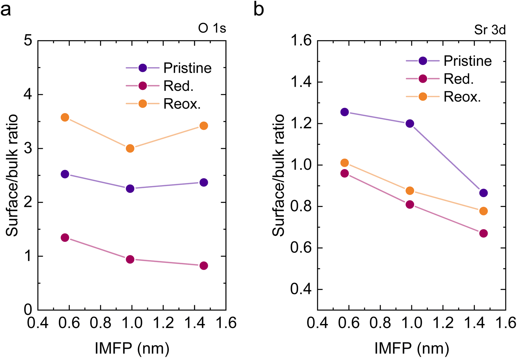 | ||
| Fig. 7 Surface/bulk component ratio of (a) O 1s and (b) Sr 3d, calculated based on NAP-XPS fitted data at each photon energy (705, 950, and 1250 eV for O 1s and 260, 510, and 810 eV for Sr 3d) depicted as a function of the corresponding IMFP. | ||
Overall, in this section the surface changes associated with the exsolution process have been identified, paying particular attention to the variations suffered by the cations that do not participate in the NP exsolution. This knowledge is paramount since the perovskite surface is key in many relevant electrocatalytic processes.
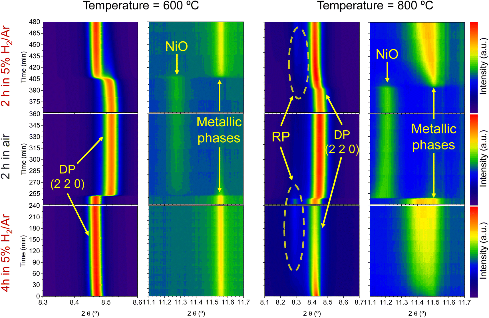 | ||
| Fig. 8 Time-resolved in situ XRD contour maps for the evaluation of exsolution regeneration. Temperature was raised to either 600 (left panels) or 800 °C (right panels) in 5% H2/Ar atmosphere. After reaching the target temperature, reduction was carried out for 4 h, followed by an oxidation step of 2 h in synthetic air. Finally, a last reduction step of 2 h was performed by changing the atmosphere back to 5% H2/Ar. Note that the x-axis scales from the 600 °C and the 800 °C differ for the panels showing low 2θ diffraction patterns. Double perovskite phase and Ruddlesden–Popper phase are labeled as DP and RP, respectively. | ||
Regarding the 11.1–11.7° region, a peak appearing at 2θ = 11.55° is observed in the first 4 hours reduction step. This peak is ascribed to the formation of metallic Ni from the reduction of NiO impurities (see Fig. 1). During the 4 hours treatment at 600 °C, this signal did not exhibit any noticeable shift. Upon the change to the oxidizing atmosphere, this metallic Ni phase progressively transitions into NiO (peak at 11.27°). The onset of this reaction happens also after 15 min exposure to air atmosphere, just like the double perovskite oxidation. Although we have observed ternary alloy exsolution after a 4 hours treatment at 600 °C with HRFESEM and TEM in previous work,20 here it was not possible to infer its presence with in situ XRD, probably hampered by the NiO/Ni impurities redox process. When switching again to the reductive atmosphere in the second treatment under H2, the NiO phase was reduced to Ni again after 45 min of exposure, coinciding with the double perovskite reduction.
The same redox cyclic process was evaluated at 800 °C, finding remarkable differences. First, it was observed that the main reflection of the cubic double perovskite decreased in intensity during the 4 hours reductive treatment, with a concomitant phase transition from double perovskite to an RP phase. This is better observed in Fig. 9a, where selected diffractograms taken with 30 min intervals are plotted. It can be observed that the RP phase appears after 30 min exposure with a main peak located at 8.3°. In this 4 hours treatment, the transition to the RP phase is partial, reaching a lower conversion extent if compared with ex situ analyses after reduction in a tubular furnace.20 After changing to the oxidation step, firstly, the RP phase disappears, and secondly, the double perovskite main peak shifts to higher angles. Thus, the transformation between double perovskite and RP phases is reversible, which is consistent with previous reports.34 In this case, the transformation occurred during 7.5 min of exposure to air, while at 600 °C it took 15 min, indicating that the increase in temperature helped also in speeding up the redox transitions. This event was also observed in the second reduction step. Here, the abrupt shift to lower 2θ values happened after ∼30 min under reducing conditions, together with the RP formation onset. Fig. S8† compares the main reflections after the last 2 hours reduction step for both 600 and 800 °C. It can be observed that at 800 °C, the peak intensity is lower than at 600 °C, it appears at lower 2θ values (higher reduction extent at higher temperatures), and the presence of the RP phase, reflecting the remarkable impact of the temperature increase on the exsolution process, which ultimately affect the electrochemical properties and durability of the electrode.20 It is worth noting that, in the same figure, some slight signal can be seen at around 2θ = 8.35°, which might indicate the slight formation of RP phase at 600 °C after the second reduction step, not observed during the 4 hours reduction period. Nevertheless, this peak appears in almost negligible amounts.
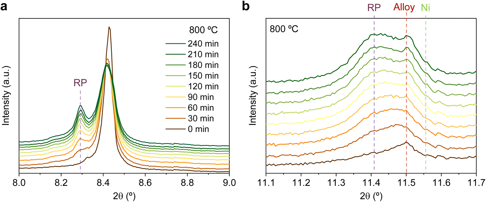 | ||
| Fig. 9 Time-resolved in situ XRD at 800 °C, during the first reduction step in 5% H2/Ar for (a) the 8–9° region and (b) the 11.1–11.7° region, exhibiting the formation of the Ruddlesden–Popper phase (RP), the exsolution of ternary alloyed NPs and the emergence of Ni caused by the reduction of minor NiO impurities. | ||
Fig. 9b depicts the 11.1–11.7° region, where metallic phases associated with the ternary alloy exsolution are expected to appear. At the beginning of the isothermal 4 hours treatment, an asymmetric reflection is already observed between 11.35 and 11.55°. By increasing the exposure time, the reflection exhibits changes affecting the region around 11.47° and later affecting the region around 11.40°. The former is ascribed to the growth of the exsolved ternary alloyed NPs, whereas the latter corresponds to the (0 0 10) reflection of the RP phase (the growth of this minor RP reflection is simultaneous to the one observed in Fig. 9a). The minor initial peak observed at 11.55° is ascribed to metallic Ni originating from the reduction of NiO impurities, whereas, at 11.50°, the exsolved metallic phase can already be observed. Fig. 9b indicates that the major exsolved NP growth occurs at the early stages of the isothermal reduction process, namely in the first 30 minutes. As commented in Section 3.1.1, the nucleation of the exsolved NPs already occurred during the heating stage under reducing conditions (Fig. 1). Thus, it is expected that time will mainly play a key role in the growth and/or consolidation of the already existing exsolved NPs rather than in forming new ones.
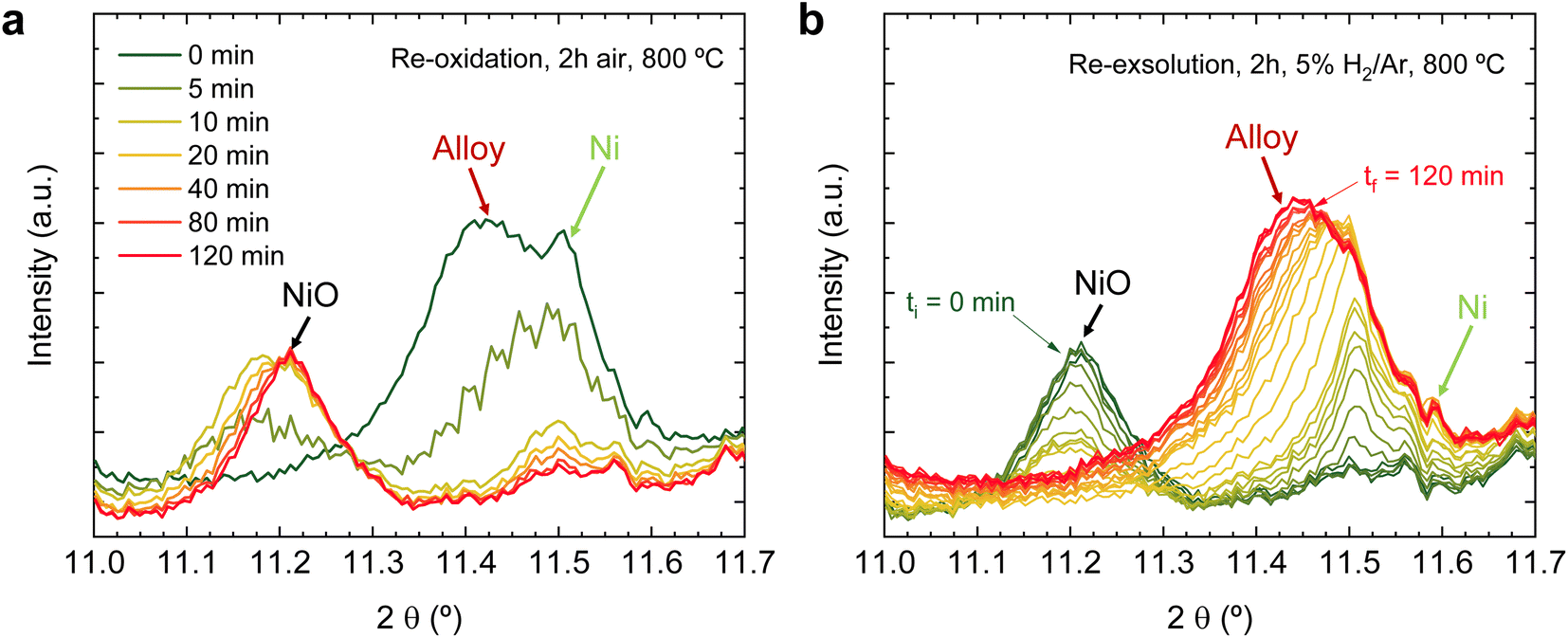
After the initial 4 hours reduction step, changes affecting the metallic phases were studied in the subsequent re-oxidation and second reduction treatments. Fig. 10a depicts this 2 hours re-oxidation step. Overall, it is a very fast process. Just after 5 min, the region associated (∼11.4°) with the (0 0 10) RP reflection illustrates that this phase remarkably decreases its presence and totally vanishes after 10 minutes, confirming that the oxidation of RP to double perovskite is much faster than the reverse path. Additionally, after 5 re-oxidation minutes, a broad peak appears between 11.1 and 11.3°, which centers around 11.2°. The fact that this peak is rather broad might indicate the presence of two different oxidized species emerging simultaneously. One would be NiO from the oxidation of Ni-segregated impurities, as already observed in the experiments at 600 °C (Fig. 8). The second one could be ascribed to oxidation of the exsolved NPs, so the exsolved ternary alloys are partly re-oxidized during the initial stages of the re-oxidation. Only slight differences were observed between 10- and 120 min exposure in the diffraction patterns (Fig. 10a). First, the peak at around 11.2° progressively increases, indicating NiO formation due to re-oxidation, suggesting a non-complete re-dissolution of Ni metallic species. Secondly, in the 2θ region between 11.5-11.6°, it is observed that the signals associated with the FeCoNi exsolved NPs and Ni0 narrow but are not completely gone. This indicates that the 2 hours re-oxidation was insufficient for a complete re-dissolution of the metallic exsolved NPs back to the perovskite lattice, especially for Ni. It is worth mentioning that the in situ XRD setup might be conditioning these results. Low gas flows (1 mL min−1) were introduced through the packed oxide powder in the capillary. This fact might cause preferential paths, hence hampering total re-oxidation of the exsolved NPs, explaining the minor metallic signals remaining. This adequately correlates with the HRFESEM micrographs taken after the in situ NAP-XPS re-oxidation, where, in some areas, exsolved NPs were still present (Fig. 3d). The precise composition of these remaining NPs and further morphological changes under reduction/oxidation cycles will be explored in Section 3.2.3. Using similar compositions, using in situ HRFESEM, Lv et al. found that, before total re-dissolution, CoFe alloys formed CoFeOx nanosheets as an intermediate step.34 In this line, Santaya et al. observed that, after 1 h oxidation, FeNi3 exsolved NPs transform in Ni-rich (Ni0.9Fe0.1)O oxide NPs over the surface. The authors also explained that after 24 hours oxidation, the surface was free of NPs.30 Therefore, it seems that exsolved NP oxidation is an intermediate step before total re-dissolution to the host oxide, which is time (and temperature) dependent and might also be conditioned by the material.
 | ||
| Fig. 10 Time-resolved in situ XRD at 800 °C, during (a) the re-oxidation step of 2 h under air atmosphere followed by (b) the second reduction step in 5% H2/Ar for the region between 11.1 and 11.7°. | ||
Finally, Fig. 10b shows the changes occurring during the second reduction step, that is, the re-exsolution experiment. It should be noted here that this exsolution treatment is performed purely isothermally, while in Section 3.1.1, the formation of ternary alloyed exsolved NPs began while applying a heating ramp. This might have some relevant implications for the NP's growth, as recently reported by Santaya et al.,36 who analyzed isothermal vs. stepwise reduction paths, finding remarkable differences in the amount of metallic Fe exsolved, NP size, population, and even in Sr segregations. This might, in turn, explain the slight differences in the peak shapes when comparing the diffractograms after the first and second reduction treatments. Namely, during the first treatment there was always a sharp peak termination at 11.50° (Fig. 9b). However, during the second treatment, the signal, starting at 11.50° in the initial exsolution stages, shifts to 11.45° at the end of the 2 hours reduction (Fig. 10b). This shift might be related to alterations in the NP composition that occur during the exsolution process. This aspect will be explored in more detail in the following section.
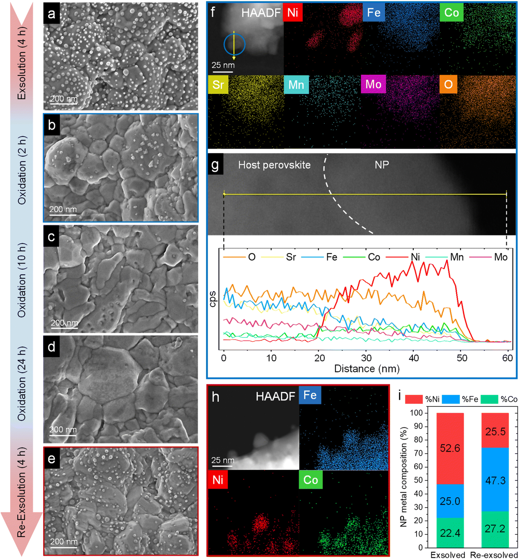 | ||
| Fig. 11 HRFESEM micrographs of Sr2FeCo0.2Ni0.2Mn0.1Mo0.5O6−δ after ex situ 800 °C, 4 h exsolution in 5% H2/Ar flow (a). The same sample after re-oxidation at 800 °C in air for 2 (b), 10 (c), and 24 h (d). Following the 24 h re-oxidation, another reduction treatment (800 °C, 4 h, 5% H2/Ar) was performed for re-exsolution (e). HAADF and XEDS map images of the material after 2 h re-oxidation treatment (f) and line-scan analysis (yellow arrow) for one of the NPs, highlighted in blue (g). These compositional analyses reveal that, after re-oxidation, the remaining NPs are mainly composed of NiO. HAADF and map images of re-exsolved NPs, revealing that after re-exsolution ternary FeCoNi ternary alloys are also obtained (h). Compositional comparison of the exsolved NPs after first exsolution and re-exsolution (i). Compositional information of the first exsolution NPs were taken with permission from ref. 20. | ||
After re-oxidation, re-exsolution was performed for 4 h at 800 °C, resulting in the emergence of new spherical NPs spread along the surface of the material (Fig. 11e). However, these NPs are morphologically and compositionally different from the original exsolved ones. Firstly, the exsolution extent narrows after re-exsolution since the mean size of the NPs is lower (22.5 versus 14.7 nm), and so does the population (612 against 471 μm−2 after the first exsolution and re-exsolution, respectively). NP mean size distribution histograms for both treatments are depicted in Fig. S9.† Regarding their composition, ternary FeCoNi alloyed NPs are, again, obtained according to XEDS analyses (Fig. 11h) but with remarkably different composition ratios (Fig. 11i and S10†). Namely, the re-exsolved NPs main component is Fe (47.3%) instead of Ni (25.5%), making a notable difference with the original exsolved NPs (25.0 and 52.6% of Fe and Ni, respectively). At the same time, the Co content exhibits no significant alterations (27.2 and 22.4% for re-exsolved and exsolved NPs, respectively). So then, despite the NAP-XPS in situ data that suggested faster migration kinetics during the exsolution process for Ni (Fig. 2d), Fe exhibited higher exsolution rates after re-oxidation and subsequent re-exsolution. This Fe-enrichment found by XEDS-TEM might be related to the observed shift to lower 2θ values affecting the metallic peak when compared to the first exsolution in the time-resolved in situ XRD analyses (Fig. 10b). Indeed, this shift indicates that the compositional change is accompanied by a lattice expansion, which, based on the work of Santaya et al.,36 might be explained by a gradual increase in Fe concentration in the metallic NP. This makes sense if considering, for instance, the different lattice volumes for the cubic structures of Ni (41.97 Å3) and FeNi3 (43.26 Å3). In this case, Fe incorporation in the metallic phase causes a lattice expansion concerning a Ni-rich composition. Thus, the obtained results in this isothermal exsolution at 800 °C suggest that ternary alloy exsolution is followed by a Fe enrichment during the 2 hours treatment, leading to a different final ternary alloy composition, confirming the XEDS observations. The surface re-arrangement occurring during exsolution and later re-oxidation might trigger the morphological and compositional changes in the re-exsolved NPs (Fig. 12). In Santaya et al. previous work, a re-arrangement based in a Sr and O enrichment of the outer-surface layer during re-oxidation (after FeNi alloyed NPs exsolution) is suggested.30 In this work, an O-enrichment has been also reported after re-oxidation compared to pristine state (Fig. 7a), which does not apply for Sr (Fig. 7b). Upon re-oxidation, however, Fe is fully reincorporated into the host perovskite, whereas part of the Ni remains on the surface as Ni-rich oxidized NPs (almost fully re-incorporated after long oxidation times). This fact might have an impact in terms of a Fe-enrichment of the outer-surface layer of the host perovskite (Fig. 11g). So then, the described re-arrangement definitely affects the outmost atomic layers (the ones involved with the exsolution process) of the host perovskite, thus conditioning the latter re-exsolution.
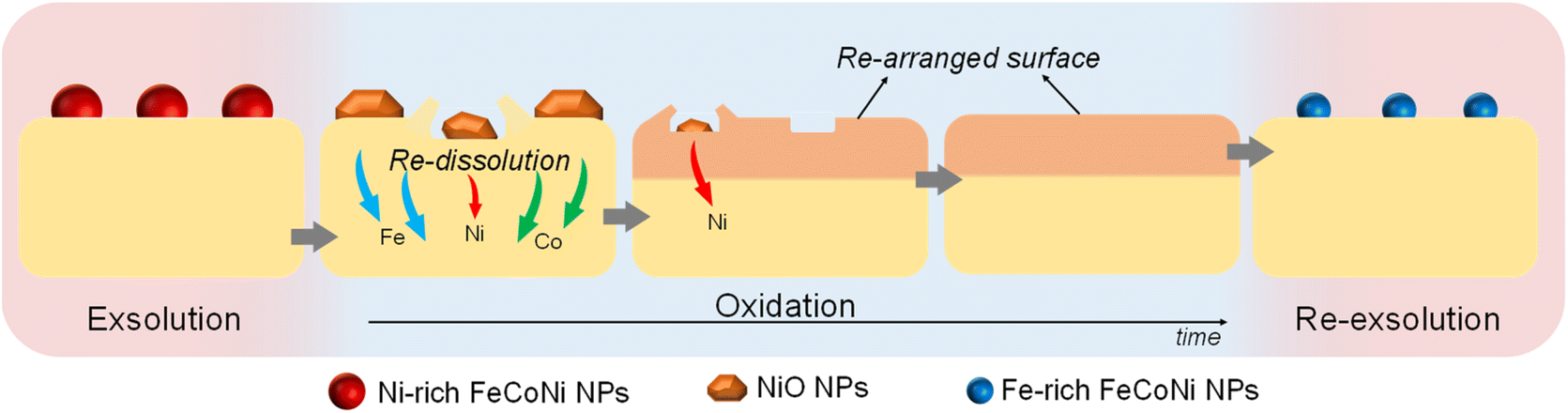 | ||
| Fig. 12 Schematic representation of the ex situ redox processes affecting the exsolved NPs in Sr2FeCo0.2Ni0.2Mn0.1Mo0.5O6−δ, and their latter re-dissolution and re-exsolution. | ||
In summary, the mechanistic insights obtained in the present work expand the design space of multielemental nanoparticle exsolution, which could have profound implications in several applications for renewable energy storage and conversion. Here, we have demonstrated that exsolution reversibility comes at the cost of a compositional re-arrangement. This property could be wisely engineered to circumvent the initial observations in which cations with more favorable migration properties (e.g. Ni) were in higher concentration, whereas after redox cycling, one could tune the composition to have a higher content of Fe. This will be especially useful for processes in which metallic Fe is the active species, such as ammonia synthesis or cracking. This is highly relevant since, currently, many works delve into the use of ammonia as a hydrogen carrier to be used as fuel in fuel cells.64 Hence, the composition of the multicomponent exsolved nanoparticles could be designed à la carte by applying a series of redox treatments or by adjusting the process conditions (time, temperature, pressure) to obtain a targeted compound.
4. Conclusions
In this work, the exsolution, re-dissolution, and regeneration of ternary alloyed nanoparticles were monitored using synchrotron-based in situ NAP-XPS and XRD measurements. In addition, special attention was paid to crystallographic and surface transformations occurring during the exsolution/re-dissolution process. Both NAP-XPS and XRD revealed the formation of the ternary alloy nanoparticles during a temperature-programmed heating step under reducing conditions. Contrary to some mechanistic literature reports, the exsolution studied here apparently was not driven by the isolated migration of each cation followed by alloying in the surface. However, nucleation sites, which might be induced by the more reducible Ni cations, tended to form along the heating step, leading to nanoparticle growth during the following temperature-dwelling step. Consistent with STEM-XEDS results, the NAP-XPS data showed a higher concentration of metallic Ni species, followed by Co and Fe. Additionally, the presence of Mo5+ suggested by NAP-XPS also confirmed the partial crystallographic transformation of the double perovskite phase into a Ruddlesden–Popper structure, which was also inferred by in situ XRD. This transformation is fully reversible upon re-oxidation re-reduction cycles, being the oxidation from the Ruddlesden–Popper phase to the double perovskite a much faster process than the reduction. Ternary alloyed nanoparticle re-dissolution was confirmed by NAP-XPS, XRD, and HRFESEM, although under the employed conditions in this work, full nanoparticle re-dissolution back to the perovskite was not achieved. In this process, oxidized intermediate phases were detected, acting as a previous step in the exsolved nanoparticle re-dissolution. Nanoparticle re-exsolution was also observed by in situ XRD. Interestingly, performing the exsolution process isothermally induced changes in the metallic peak positions assigned to the exsolved nanoparticles, suggesting compositional variations throughout the re-exsolution process. This was corroborated by ex situ redox experiments via XEDS analyses, pointing to an NP Fe-enrichment after re-exsolution. Overall, the results presented here shed light on the detailed crystallographic and surface chemistry changes occurring in the exsolution of ternary alloyed nanoparticles. This knowledge can be used to optimize alloy exsolution in double perovskite electrodes and, in turn, improve their electrocatalytic properties.Data availability
The authors confirm that the data supporting the findings of this study are available within the article and its ESI.† All the experimental data will be available on request.Conflicts of interest
There are no conflicts of interest to declare.Acknowledgements
The project that gave rise to these results received the support of a fellowship from “la Caixa” Foundation (ID 100010434). The fellowship code is LCF/BQ/PI20/11760015. Financial support by Generalitat Valenciana (CIPROM/2022/10) and by the Spanish Ministry of Science and Innovation (PID2022-139663OB-100 and CEX2021-001230-S) grants funded by MCIN/AEI/10.13039/501100011033. We thank the financial support of the Helmholtz Initiative and Networking Fund through the HZB-BASF project ENERCHEM: Energiespeicherung durch Chemie. These experiments were performed at BL24-CIRCE (proposal number 2022035801) and BL04-MSPD (2022025687) beamlines at ALBA Synchrotron with the collaboration of ALBA staff. The authors thank Alexander Missyul for the help with setting up the in situ XRD experiments and Elena Vicente for the support on the NAP-XPS experimental campaign. Authors acknowledge the use of instrumentation as well as the technical advice provided by the National Facility ELECMI ICTS, node “División de Microscopía Electrónica” at Universidad de Cádiz and project PID2022-142312NB-I00. We thank the support of the Electronic Microscopy Service of the Universitat Politècnica de València.References
- K. Kousi, C. Tang, I. S. Metcalfe and D. Neagu, Small, 2021, 17, 2006479 Search PubMed.
- J. H. Kim, J. K. Kim, J. Liu, A. Curcio, J.-S. Jang, I.-D. Kim, F. Ciucci and W. Jung, ACS Nano, 2021, 15, 81–110 Search PubMed.
- J. Zhang, M. M.-R. Gao and J.-L. Luo, Chem. Mater., 2020, 32, 5424–5441 CrossRef CAS.
- D. Neagu, J. T. S. Irvine, J. Wang, B. Yildiz, A. K. Opitz, J. Fleig, Y. Wang, J. Liu, L. Shen, F. Ciucci, B. A. Rosen, Y. Xiao, K. Xie, G. Yang, Z. Shao, Y. Zhang, J. Reinke, T. A. Schmauss, S. A. Barnett, R. Maring, V. Kyriakou, U. Mushtaq, M. N. Tsampas, Y. Kim, R. O'Hayre, A. J. Carrillo, T. Ruh, L. Lindenthal, F. Schrenk, C. Rameshan, E. I. Papaioannou, K. Kousi, I. S. Metcalfe, X. Xu and G. Liu, JPhys Energy, 2023, 5, 031501 Search PubMed.
- A. J. Carrillo and J. M. Serra, Catalysts, 2021, 11, 741 Search PubMed.
- S. Joo, K. Kim, O. Kwon, J. Oh, H. J. Kim, L. Zhang, J. Zhou, J. Wang, H. Y. Jeong, J. W. Han and G. Kim, Angew. Chem., Int. Ed., 2021, 60, 15912–15919 CrossRef CAS PubMed.
- M. A. Naeem, P. M. Abdala, A. Armutlulu, S. M. Kim, A. Fedorov and C. R. Müller, ACS Catal., 2020, 10, 1923–1937 CrossRef CAS.
- Y. H. Kim, Y. Kang, S. Jo, H. Jeong, D. Neagu and J. Myung, Chem. Eng. J., 2022, 441, 136025 CrossRef CAS.
- A. J. Carrillo, K. J. Kim, Z. D. Hood, A. H. Bork and J. L. M. Rupp, ACS Appl. Energy Mater., 2020, 3, 4569–4579 CrossRef CAS.
- S.-K. Otto, K. Kousi, D. Neagu, L. Bekris, J. Janek and I. S. Metcalfe, ACS Appl. Energy Mater., 2019, 2, 7288–7298 Search PubMed.
- K. Kousi, D. Neagu, L. Bekris, E. I. Papaioannou and I. S. Metcalfe, Angew. Chem., Int. Ed., 2020, 59, 2510–2519 Search PubMed.
- K. Kousi, D. Neagu, L. Bekris, E. Calì, G. Kerherve, E. I. Papaioannou, D. J. Payne and I. S. Metcalfe, J. Mater. Chem. A, 2020, 8, 12406–12417 Search PubMed.
- A. J. Carrillo, L. Navarrete, M. Laqdiem, M. Balaguer and J. M. Serra, Mater. Adv., 2021, 2, 2924–2934 RSC.
- V. Kyriakou, R. K. Sharma, D. Neagu, F. Peeters, O. De Luca, P. Rudolf, A. Pandiyan, W. Yu, S. W. Cha, S. Welzel, M. C. M. Sanden and M. N. Tsampas, Small Methods, 2021, 2100868 CrossRef CAS PubMed.
- X. Li, L. Dai, Z. He, W. Meng, Y. Li and L. Wang, Sens. Actuators, B, 2019, 298, 126827 CrossRef CAS.
- X. Li, L. Dai, Z. He, W. Meng, Y. Li and L. Wang, Sens. Actuators, B, 2019, 298, 126854 CrossRef CAS.
- J. Spring, E. Sediva, Z. D. Hood, J. C. Gonzalez-Rosillo, W. O'Leary, K. J. Kim, A. J. Carrillo and J. L. M. Rupp, Small, 2020, 16, 2003224 Search PubMed.
- D. Neagu, T.-S. Oh, D. N. Miller, H. Ménard, S. M. Bukhari, S. R. Gamble, R. J. Gorte, J. M. Vohs and J. T. S. Irvine, Nat. Commun., 2015, 6, 8120 Search PubMed.
- A. J. Carrillo, A. López-García, B. Delgado-Galicia and J. M. Serra, Chem. Commun., 2024, 60, 7897–8007 RSC.
- A. López-García, L. Almar, S. Escolástico, A. B. Hungría, A. J. Carrillo and J. M. Serra, ACS Appl. Energy Mater., 2022, 5, 13269–13283 Search PubMed.
- D. Neagu, V. Kyriakou, I. L. Roiban, M. Aouine, C. Tang, A. Caravaca, K. Kousi, I. Schreur-Piet, I. S. Metcalfe, P. Vernoux, M. C. M. Van De Sanden and M. N. Tsampas, ACS Nano, 2019, 13, 12996–13005 CrossRef CAS PubMed.
- C. Tang, K. Kousi, D. Neagu and I. S. Metcalfe, Chem.–Eur. J., 2021, 27, 6666–6675 Search PubMed.
- K. Zhu, T. Wu, M. Li, R. Lu, X. Zhu and W. Yang, J. Mater. Chem. A, 2017, 5, 19836–19845 RSC.
- A. I. Tsiotsias, B. Ehrhardt, B. Rudolph, L. Nodari, S. Kim, W. Jung, N. D. Charisiou, M. A. Goula and S. Mascotto, ACS Nano, 2022, 16, 8904–8916 CrossRef CAS PubMed.
- E. I. Papaioannou, D. Neagu, W. K. W. Ramli, J. T. S. Irvine and I. S. Metcalfe, Top. Catal., 2019, 62, 1149–1156 CrossRef CAS.
- Y. F. Sun, J. H. Li, L. Cui, B. Hua, S. H. Cui, J. H. Li and J. L. Luo, Nanoscale, 2015, 7, 11173–11181 RSC.
- D. Papargyriou, D. N. Miller and J. T. S. Irvine, J. Mater. Chem. A, 2019, 7, 15812–15822 RSC.
- T. Zhu, H. E. Troiani, L. V. Mogni, M. Han and S. A. Barnett, Joule, 2018, 2, 478–496 CrossRef CAS.
- H. Lv, L. Lin, X. Zhang, D. Gao, Y. Song, Y. Zhou, Q. Liu, G. Wang and X. Bao, J. Mater. Chem. A, 2019, 7, 11967–11975 RSC.
- M. Santaya, C. E. Jiménez, H. E. Troiani, E. A. Carbonio, M. D. Arce, L. M. Toscani, R. Garcia-Diez, R. G. Wilks, A. Knop-Gericke, M. Bär and L. V. Mogni, J. Mater. Chem. A, 2022, 10, 15554–15568 RSC.
- B. Delgado-Galicia, A. López-García, A. J. Carrillo and J. M. Serra, Solid State Ionics, 2024, 410, 116532 CrossRef CAS.
- W. Zhang, H. Wang, K. Guan, J. Meng, Z. Wei, X. Liu and J. Meng, ACS Appl. Mater. Interfaces, 2020, 12, 461–473 CrossRef CAS PubMed.
- S. Liu, K. T. Chuang and J. L. Luo, ACS Catal., 2016, 6, 760–768 CrossRef CAS.
- H. Lv, L. Lin, X. Zhang, Y. Song, H. Matsumoto, C. Zeng, N. Ta, W. Liu, D. Gao, G. Wang and X. Bao, Adv. Mater., 2020, 32, 1906193 CrossRef CAS PubMed.
- M. Santaya, H. E. Troiani, A. Caneiro and L. V. Mogni, ACS Appl. Energy Mater., 2020, 3, 9528–9533 CrossRef CAS.
- M. Santaya, C. E. Jiménez, M. D. Arce, E. A. Carbonio, L. M. Toscani, R. Garcia-Diez, A. Knop-Gericke, L. V. Mogni, M. Bär and H. E. Troiani, Int. J. Hydrogen Energy, 2023, 48, 38842–38853 Search PubMed.
- Y. Jiang, Y. Yang, C. Xia and H. J. M. Bouwmeester, J. Mater. Chem. A, 2019, 7, 22939–22949 Search PubMed.
- B.-W. Zhang, M.-N. Zhu, M.-R. Gao, X. Xi, N. Duan, Z. Chen, R.-F. Feng, H. Zeng and J.-L. Luo, Nat. Commun., 2022, 13, 4618 CrossRef CAS PubMed.
- H. Tanaka, M. Taniguchi, M. Uenishi, N. Kajita, I. Tan, Y. Nishihata, J. Mizuki, K. Narita, M. Kimura and K. Kaneko, Angew. Chem., 2006, 118, 6144–6148 CrossRef.
- H. Tanaka, M. Uenishi, M. Taniguchi, I. Tan, K. Narita, M. Kimura, K. Kaneko, Y. Nishihata and J. Mizuki, Catal. Today, 2006, 117, 321–328 CrossRef CAS.
- V. B. Vert, F. V. Melo, L. Navarrete and J. M. Serra, Appl. Catal., B, 2012, 115–116, 346–356 CrossRef CAS.
- Y. Nishihata, J. Mizuki, T. Akao, H. Tanaka, M. Uenishi, M. Kimura, T. Okamoto and N. Hamada, Nature, 2002, 33, 8 Search PubMed.
- V. Pérez-Dieste, L. Aballe, S. Ferrer, J. Nicolàs, C. Escudero, A. Milán and E. Pellegrin, J. Phys.: Conf. Ser., 2013, 425, 072023 CrossRef.
- S. Tanuma, C. J. Powell and D. R. Penn, J. Electron Spectrosc. Relat. Phenom., 1990, 52, 285–291 CrossRef CAS.
- C. J. Powell and A. Jablonski, J. Surf. Anal., 2002, 9, 322–325 CrossRef CAS.
- J. Moulder, W. Stickle, P. Sobol and K. Bomben, Handbook of X-ray photoelectron spectroscopy, 1992 Search PubMed.
- J. Wang, D. Kalaev, J. Yang, I. Waluyo, A. Hunt, J. T. Sadowski, H. L. Tuller and B. Yildiz, J. Am. Chem. Soc., 2023, 145, 1714–1727 CrossRef CAS PubMed.
- A. Nenning, A. K. Opitz, C. Rameshan, R. Rameshan, R. Blume, M. Hävecker, A. Knop-Gericke, G. Rupprechter, B. Klötzer and J. Fleig, J. Phys. Chem. C, 2016, 120, 1461–1471 CrossRef CAS PubMed.
- O. Kwon, S. Joo, S. Choi, S. Sengodan and G. Kim, JPhys Energy, 2020, 2, 032001 CrossRef CAS.
- O. Kwon, K. Kim, S. Joo, H. Y. Jeong, J. Shin, J. W. Han, S. Sengodan and G. Kim, J. Mater. Chem. A, 2018, 6, 15947–15953 RSC.
- T. Tan, Z. Wang, M. Qin, W. Zhong, J. Hu, C. Yang and M. Liu, Adv. Funct. Mater., 2022, 32, 2202878 CrossRef CAS.
- Z. Du, H. Zhao, S. Yi, Q. Xia, Y. Gong, Y. Zhang, X. Cheng, Y. Li, L. Gu and K. Świerczek, ACS Nano, 2016, 10, 8660–8669 CrossRef CAS PubMed.
- H. Lv, T. Liu, X. Zhang, Y. Song, H. Matsumoto, N. Ta, C. Zeng, G. Wang and X. Bao, Angew. Chem., Int. Ed., 2020, 59, 15968–15973 CrossRef CAS PubMed.
- J. Wang, K. Syed, S. Ning, I. Waluyo, A. Hunt, E. J. Crumlin, A. K. Opitz, C. A. Ross, W. J. Bowman and B. Yildiz, Adv. Funct. Mater., 2022, 32, 1–15 Search PubMed.
- H. Summerer, A. Nenning, C. Rameshan and A. K. Opitz, EES Catal., 2023, 1, 274–289 RSC.
- J. Wang, J. Yang, A. K. Opitz, W. Bowman, R. Bliem, G. Dimitrakopoulos, A. Nenning, I. Waluyo, A. Hunt, J.-J. Gallet and B. Yildiz, Chem. Mater., 2021, 33, 5021–5034 CrossRef CAS.
- H. Lv, L. Lin, X. Zhang, R. Li, Y. Song, H. Matsumoto, N. Ta, C. Zeng, Q. Fu, G. Wang and X. Bao, Nat. Commun., 2021, 12, 5665 CrossRef CAS PubMed.
- A. J. Carrillo, A. H. Bork, T. Moser, E. Sediva, Z. D. Hood and J. L. M. Rupp, Adv. Energy Mater., 2019, 9, 1803886 CrossRef.
- Q. H. Wu, M. Liu and W. Jaegermann, Mater. Lett., 2005, 59, 1480–1483 CrossRef CAS.
- P. A. Spevack and N. S. McIntyre, J. Phys. Chem., 1992, 96, 9029–9035 CrossRef CAS.
- E. J. Crumlin, E. Mutoro, W. T. Hong, M. D. Biegalski, H. M. Christen, Z. Liu, H. Bluhm and Y. Shao-Horn, J. Phys. Chem. C, 2013, 117, 16087–16094 CrossRef CAS.
- B. Koo, K. Kim, J. K. Kim, H. Kwon, J. W. Han and W. C. Jung, Joule, 2018, 2, 1476–1499 CrossRef CAS.
- C. Riedl, M. Siebenhofer, A. Nenning, A. Schmid, M. Weiss, C. Rameshan, A. Limbeck, M. Kubicek, A. K. Opitz and J. Fleig, J. Mater. Chem. A, 2022, 10, 14838–14848 RSC.
- I. Lucentini, X. Garcia, X. Vendrell and J. Llorca, Ind. Eng. Chem. Res., 2021, 60, 18560–18611 CrossRef CAS.
Footnote |
| † Electronic supplementary information (ESI) available. See DOI: https://doi.org/10.1039/d4ta03146f |
| This journal is © The Royal Society of Chemistry 2024 |