
Ruthenium supported on zirconia–carbon nanocomposites derived by using UiO-66 for efficient photothermal catalytic CO2 reduction†
Huiling
Wang
abc,
Qiang
Li
bce,
Jing
Chen
 *de and
Hongpeng
Jia
*bce
*de and
Hongpeng
Jia
*bce
aCollege of JunCao Science and Ecology (College of Carbon Neutrality), Fujian Agriculture and Forestry University, Fuzhou 350002, China
bXiamen Key Laboratory of Materials for Gaseous Pollutant Control, Institute of Urban Environment, Chinese Academy of Sciences, Xiamen 361021, China. E-mail: hpjia@iue.ac.cn; Fax: +86-592-6190767; Tel: +86-592-6190767
cKey Laboratory of Urban Pollutant Conversion, Institute of Urban Environment, Chinese Academy of Sciences, Xiamen 361021, China
dFujian Institute of Research on The Structure of Matter, Chinese Academy of Sciences, Fuzhou 350002, China. E-mail: jing.chen@fjirsm.ac.cn
eUniversity of Chinese Academy of Sciences, Beijing 100049, China
First published on 16th May 2024
Abstract
Resource utilization of carbon dioxide (CO2) is an effective strategy to mitigate global warming and achieve carbon neutrality and peak carbon goals. It is well known that different preparation methods affect the catalytic performance of catalysts. Herein, we designed an efficient Ru–ZrO2/C catalyst for photothermal catalytic CO2 reduction by pretreating UiO-66 in a N2 atmosphere and then loading Ru species. Compared to the reference sample of Ru/ZrO2 obtained by calcining UiO-66 in an air atmosphere, Ru–ZrO2/C exhibits much superior catalytic activity under full-spectrum light irradiation with a methane yield of 504.1 mmol g−1 h−1 and selectivity of 98.9%, respectively. In addition, the catalytic performance of Ru–ZrO2/C for photothermal CO2 methanation remains stable without obvious reduction in a 24 hour continuous test. The physicochemical characterization studies of Ru–ZrO2/C determine that the remarkable heat resistance, effective light-heat conversion ability, abundant oxygen vacancies, low-valence Ru, and good CO2 adsorption properties are responsible for the enhanced performance of photothermal CO2 hydrogenation. This work expands the application of MOFs as precursors and provides an effective guide for designing highly efficient photothermal catalysts for solar fuel production.
1 Introduction
In the face of increasingly serious environmental and energy problems, carbon neutrality has become the consensus of the international community.1 Resource utilization of carbon dioxide (CO2) could mitigate the adverse effects of global warming and provide potential solutions to the problems of the energy crisis. However, the chemical stability of the CO2 molecule necessitates high reaction temperatures to break the carbon–oxygen double bond, even with a suitable catalyst. Utilizing renewable solar energy for photothermal CO2 hydrogenation provides an environment-friendly solution to mitigate climate degradation, produce alternative fuels, and promote CO2 recycling. In particular, the excellent absorption properties of the photothermal catalyst in the solar spectrum are utilized in the photothermal CO2 methanation reaction, which can efficiently convert light into heat and provide the same amount of energy as conventional thermal catalysis. The thermal energy can be rapidly transferred to the surface interface and active sites of the photothermal catalyst, promoting charge transfer and the photothermal catalytic reaction rate. The photothermal CO2 hydrogenation reaction is a complex chemical process due to differences in catalyst properties, reaction temperatures, and pressures, resulting in the hydrogenation of CO2 to formate (HCOOH),2 ethanol,3 methanol,4,5 methane,6–8 and lower olefins9 in the actual reaction. Among these products, CH4 is a clean and nontoxic ideal energy fuel with significant practical potential. Therefore, the research of CO2 methanation has currently become one of the hot spots in catalytic reaction research.10,11In recent years, metal–organic frameworks (MOFs) have garnered significant attention due to their unique properties, including controllable chemical structures, uniform pores, and tunable electronic structures.12–15 In previous literature studies, MOFs were frequently employed in the photocatalytic reduction of CO2 by exploiting their exceptional light adsorption properties and excellent adsorption of CO2.16–18 Besides, carbon material is also an excellent photothermal material support due to its chemical inertness, structural tunability, and excellent full-spectrum absorption characteristics.19–21 Recent research has explored novel methods for synthesizing metal oxide/porous carbon nanocomposites using MOFs as precursors, opening new avenues for catalyst development.22,23 Therefore, studies to expand the application of MOFs as a precursor and template for the preparation of metal oxide carbon nanocomposites are carried out. In turn, it is essential to study the heat treatment process of MOFs under an inert atmosphere.24 Apart from this, pyrolysis of MOFs is an effective and simple strategy for dispersing reactive metals. For instance, Ru as an active site can be well atomically dispersed on the surface of zirconia/porous carbon due to the generation of oxygen vacancies in ZrOx.24 The catalytic performance of a catalyst is influenced not only by the carrier but also by the active metal loaded on the catalyst. Ye et al. report that group VIII metals (Ru, Rh, Ni, Co, Pd, Pt, Ir, and Fe) have excellent photothermal capabilities.25 Moreover, numerous studies have shown that the less expensive noble metal Ru has excellent CO2 methanation properties.26–28 Precious metal (e.g., Ru and Rh) nanoparticles significantly increase the local temperature and activate H2 in photothermal catalysis, which triggers CO2 (or CO32−) hydrogenation.6,25,29,30
Herein, a metallic zirconium metal–organic framework (UiO-66) was used as a precursor for the preparation of zirconia–carbon nanocomposites (ZrO2/C) by heat treatment under a N2 atmosphere, while a reference support was prepared under an air atmosphere.24 Then a series of Ru-based catalysts were prepared via the impregnation method. The optimal Ru–ZrO2/C catalysts exhibit good photothermal performance during the light-driven CO2 hydrogenation reaction. The rCH4 of Ru–ZrO2/C under full-spectrum simulated sunlight conditions reaches 504.1 mmol g−1 h−1 with high selectivity (98.9%). By contrast, under the same reaction condition, the Ru/ZrO2 catalyst as a reference sample is sluggish. In addition, the activity and selectivity of Ru–ZrO2/C for photothermal CO2 methanation remain stable in a long-term test. The physicochemical characterization tests of Ru–ZrO2/C determine that the remarkable heat resistance, effective light-heat conversion ability, low-valence Ru, and good CO2 adsorption properties are responsible for the enhanced performance of photothermal CO2 hydrogenation. This demonstrates that ZrO2/C as a photothermal support has an important contribution to the catalytic performance of the catalysts. This not only expands the application of MOFs as precursors but also provides new ideas for the construction of efficiently loaded photothermal catalysts.
2 Experimental section
2.1. Materials
All chemicals were purchased from commercial sources without further processing. Zirconium chloride (ZrCl4) was obtained from Aladdin Reagent. Terephthalic acid (H2BDC, C8H6O4), N,N-dimethylformamide (DMF, C3H7NO), acetic acid (CH3COOH), ruthenium chloride trihydrate (RuCl3·3H2O), and methanol (CH3OH) were bought from Sinopharm Chemical Reagent. Ultrapure water (Millipore Milli-Q grade) with a resistivity of 18.2 MΩ cm was used for all the experiments.2.2. Sample preparation
UiO-66 was prepared by the hydrothermal method with slight modifications based on previous studies.31,32 First, 233.0 mg of ZrCl4 and 166.1 mg of H2BDC were dispersed in a Teflon-lined autoclave (100 mL) with 50.0 mL DMF. After stirring for 10 min, 3.6 mL of CH3COOH was added dropwise and stirring was continued for 30 min to form a homogeneous solution. Next, the autoclave was sealed and placed in an oven at 120 °C for 24 hours. After cooling down to ambient temperature, the precipitate was centrifuged and rinsed with methanol several times and finally dried at 100 °C for 12 hours.The two supports of zirconia–carbon nanocomposites (ZrO2/C) and zirconia (ZrO2) were prepared as follows. UiO-66 powder was annealed in a tube furnace and heated to 400 °C at a rate of 5 °C min−1 for 30 min and then to 600 °C at a rate of 2 °C min−1 for 2 hours in an N2 atmosphere (100 mL min−1). After cooling to room temperature, the black ZrO2/C was obtained. The reference support ZrO2 was obtained via annealing UiO-66 in air.
The Ru-based catalysts were fabricated via the wet impregnation method. The Ru–ZrO2/C samples were prepared as follows: first, 200 mg of ZrO2/C and a quantitative RuCl3·3H2O solution were added to 200 mL of deionized water under ultrasonic treatment for 10 min to form a suspension. Then, the suspension was stirred at 350 rpm for 6 hours at room temperature. Finally, the resulting solution was stirred in a 90 °C water bath until dry. The solids were reduced at 300 °C for 3 hours in H2 (30 mL min−1). The reference sample Ru/ZrO2 was synthesized similarly except that ZrO2 was used directly to replace ZrO2/C as the support.
2.3. Characterization
The X-ray diffraction (XRD) patterns were obtained via an X′ Pert Pro automatic powder diffractometer with Cu Kα monochromatized radiation (40 kV, 40 mA). A CNS elemental analyzer (Vario MAX) was used to measure the carbon content of the samples. Transmission electron microscopy (TEM) and high-resolution TEM (HRTEM) images were recorded using a JEM 2100 F electronic microscope. The elemental maps of the samples were obtained using an energy dispersive spectrometer (EDS), which was equipped with a TEM. Nitrogen adsorption–desorption isotherms were obtained on a Quantachrome Autosorb IQ instrument, and the mean diameter (DBJH) and specific surface area (SBET) of the samples were analyzed by Barrett–Joyner–Halenda (BJH) and Brunauer–Emmet–Teller (BET) methods, respectively. The chemical properties of the catalysts were measured via a Kratos/Shimadzu X-ray photoelectron spectrometer (XPS) equipped with AlKα radiation (1486.6 eV). All binding energies were calibrated to C 1s at 284.6 eV. Diffuse reflectance spectra (DRS) in the range of 200–800 nm were collected at room temperature using a Varian Cary 5000 ultraviolet-visible spectrophotometer with a white standard BaSO4. Photocurrent and electrochemical impedance tests both were performed in a three-electrode system with an electrochemical workstation model CHI 660E. 5 mg of the sample was ultrasonically dispersed in 1.5 mL of ethanol, and 15 μL of the sample was dropped onto FTO conductive glass with an area of π × 0.05 × 0.05 cm2 as the working electrode. Pt was used as the counter electrode, Ag/AgCl as the reference electrode, and KCl/K3Fe(CN)6/K4Fe(CN)6 as the electrolyte. Electron paramagnetic resonance (EPR) spectroscopy was carried out on a Bruker A300 spectrometer at the temperature of liquid nitrogen. The CO2 temperature-programmed desorption (CO2-TPD) experiments were executed on a Quantachrome chemisorption instrument with online mass spectroscopy (Tilon, LC-200M). About 50 mg of the sample powder was first pretreated in He flow (30 mL min−1) at 400 °C for 30 min. Second, after the sample was cooled down to 40 °C, CO2 flow (30 mL min−1) was introduced for adsorption for 1 hour, and then the physically adsorbed CO2 was removed by using He flow (30 mL min−1) for 1 hour. Finally, CO2-TPD was recorded online from 40 to 700 °C in He flow. CH4-TPD followed the same procedure, except that it used CH4 as the adsorbed gas.2.4. In situ DRIFTS analysis
In situ DRIFTS was performed to study the intermediates occurring on the catalysts on a ThermoFisher iS50 spectrometer during catalytic reduction reactions. First, the sample was pretreated in a 5% H2/Ar atmosphere flow for 30 min at 300 °C, and then cooled to ambient temperature by using a N2 stream. Next, the spectra at 25 °C were collected as the background in a N2 atmosphere. Subsequently, the gas mixture (10% CO2, 40% H2, and 50% He) was injected into the reaction cell, followed by heating to a certain temperature (light or heating conditions) and reaction for 15 min. Finally, the reacted mixed gas to detect the intermediates by TCD.2.5. Catalytic activity evaluation
The catalytic performance of the catalysts for photothermal CO2 methanation was evaluated in a vertical stainless-steel reactor with a quartz window. A 300 W xenon lamp (PLS-SXE300+, Beijing Perfect Light Technology Co. Ltd) was used as a light source for CO2 methanation. The light intensity was measured at the same position of the catalyst layer using an optical power meter (CELNP2000-2, Perfect Light). The surface temperature of the catalyst layer was measured via a thermocouple. The catalyst powder (10 mg) was placed at the center of the reactor to evaluate the catalytic performance of the catalyst in the CO2 methanation reaction. The gas mixture of H2/CO2/He with a volume ratio of 4![[thin space (1/6-em)]](https://www.rsc.org/images/entities/char_2009.gif) :1:5 was introduced into the reactor and kept for 15 min to remove air. Next, the gas mixture was continuously introduced into the stainless-steel reactor with a rate of 25 mL min−1 for CO2 methanation. UV-visible and visible-IR region were obtained through a cutoff filter to verify the different light functions in the photothermal CO2 methanation process. Meanwhile, the thermal catalytic activity evaluation was performed in a tube furnace as a comparison. Specifically, a mixture containing 10 mg of catalyst and 1 g of silica sand (size 40–60 mesh) was placed in the furnace. Besides this, the long-term stability test for CO2 methanation was conducted under the same light conditions. The low-temperature reaction was controlled by the cooling circulation tank. Concentrations of CO2, CO, and CH4 were determined by using an online gas chromatograph equipped with a flame ionization detector (FID) and a thermal conductivity detector (TCD). The yield and selectivity for CO2 methanation were calculated by using the following equations.
:1:5 was introduced into the reactor and kept for 15 min to remove air. Next, the gas mixture was continuously introduced into the stainless-steel reactor with a rate of 25 mL min−1 for CO2 methanation. UV-visible and visible-IR region were obtained through a cutoff filter to verify the different light functions in the photothermal CO2 methanation process. Meanwhile, the thermal catalytic activity evaluation was performed in a tube furnace as a comparison. Specifically, a mixture containing 10 mg of catalyst and 1 g of silica sand (size 40–60 mesh) was placed in the furnace. Besides this, the long-term stability test for CO2 methanation was conducted under the same light conditions. The low-temperature reaction was controlled by the cooling circulation tank. Concentrations of CO2, CO, and CH4 were determined by using an online gas chromatograph equipped with a flame ionization detector (FID) and a thermal conductivity detector (TCD). The yield and selectivity for CO2 methanation were calculated by using the following equations. | (1) |
 | (2) |
Here, F represents the gas flow rate (mL min−1); [CH4] and [CO] are the respective concentrations (vol%) of CH4 and CO detected by the online GC.
3 Results and discussion
3.1. Structural and morphological characterization
We utilized the supports of ZrO2/C and ZrO2 to load Ru, respectively, and the obtained samples are shown in Fig. S1.†21 The total content of C determined by using the CNS elemental analyzer in Ru–ZrO2/C and Ru/ZrO2 are 6.0 wt% and 0.6 wt%, respectively. However, no characteristic peaks of carbon are observed in XRD patterns (Fig. 1a). As shown in Table 1, the actual loading Ru contents of Ru–ZrO2/C (3.3 wt%) and Ru/ZrO2 (3.2 wt%) determined by the XRF technique are similar to each other. The XRD patterns for the samples are shown in Fig. 1a. Pure ZrO2/C, Ru–ZrO2/C, and Ru/ZrO2 clearly show diffraction peaks at 30.3°, 35.4°, 50.4°, 59.5°, and 73.2° corresponding to the typical ZrO2 crystal phase (JCPDS PDF# 96-210-0389). A weak Ru characteristic peak (44.0°, JCPDS PDF# 96-900-8514) is observed only at a Ru content of 4.6 wt% (Fig. S2†). It is noteworthy that the peaks of metal Ru are not obvious in Ru–ZrO2/C and Ru/ZrO2, suggesting that the metal Ru NPs in the Ru-based samples retain a small-size and highly dispersed state.21,33 Generally, highly dispersed and small-size Ru NPs are essential for CO2 methanation to produce high activity.34–36
 | ||
| Fig. 1 (a) XRD patterns, ZrO2 represents JCPDS PDF# 96-210-0389; (b) N2 adsorption–desorption isotherms; (c) pore distribution of the samples. | ||
| Samples | Ru loading (wt%) | S BET (m2 g−1) | D BJH (nm) | Total pore volume (cm3 g−1) |
|---|---|---|---|---|
| ZrO2/C | — | 16.6 | 3.7 | 0.03 |
| Ru–ZrO2/C | 3.3 | 35.5 | 3.7 | 0.05 |
| Ru/ZrO2 | 3.2 | 41.3 | 3.9 | 0.06 |
The N2 static adsorption–desorption isotherms were obtained to examine the adsorption properties, specific surface area, and pore size of the samples (Fig. 1b and c). Specific surface area (SBET) and total porosity were calculated using BET and BJH methods. The relationship between the structural characteristics and support of the samples is shown in Table 1. The SBET of pure ZrO2/C is 16.6 m2 g−1 while adding Ru increases the SBET value of Ru–ZrO2/C to 35.5 m2 g−1. A similar trend is also reflected in the variation of pore volume for Ru–ZrO2/C. It can be reasonably assumed that a small amount of Ru species in the precursor matrix of ZrO2/C maintains its intrinsic structure and avoids excessive shrinkage during the pyrolysis process.37 It is noteworthy that the SBET and total pore volume of the reference sample (Ru/ZrO2) are larger than that of Ru–ZrO2/C. This suggests that surface area might not be the primary factor influencing catalytic activity.
The morphology and structure of the samples were investigated using TEM and HRTEM. The TEM images of ZrO2/C and ZrO2 (Fig. S3a and b†) show a typical quasi-cubic shape. The TEM images of Ru–ZrO2/C, Ru–ZrO2/C-3h (Ru–ZrO2/C reacted for 3 hours of the photothermal catalytic reaction), and Ru/ZrO2 are shown in Fig. 2a–c. There is no obvious change in the morphology between the fresh and used Ru–ZrO2/C. HRTEM images of ZrO2/C and ZrO2 show a distance of 0.297 nm corresponding to the (111) plane of ZrO2 (Fig. S3c and d†). HRTEM patterns of Ru–ZrO2/C, Ru–ZrO2/C-3h, and Ru/ZrO2 clearly show the microstructure of ZrO2 and tiny Ru metal nanoparticles in Fig. 2d–f, where the Ru nanoparticles have a well-defined lattice with the same distance of 0.205 nm, corresponding to the (011) plane of Ru. The size of Ru nanoparticles over Ru–ZrO2/C and Ru/ZrO2 is 3.2 nm and 5.5 nm, respectively. The Ru nanoparticles are dispersed in the microstructure of ZrO2/C, and the corresponding elemental mapping diagrams are shown in Fig. 2g. However, no carbon is observed in the HRTEM image of Ru–ZrO2/C and Ru/ZrO2. According to the above analysis, no carbon is observed in the XRD pattern and HRTEM image of Ru–ZrO2/C probably because the amorphous structure of carbon is formed during the calcination process. In addition, carbon is a typical photothermal material and may provide a facile electron transport pathway for CO2 methanation.21 Moreover, the energy dispersive spectroscopy (EDS) elemental mapping shows that the elements of Ru, Zr, and O are uniformly dispersed throughout the microstructure of the cubic particles, which roughly confirms that Ru–ZrO2/C is mainly composed of C, O, Zr, and Ru combined with the HRTEM image (Fig. 2d and g).
 | ||
| Fig. 2 (a–c) TEM images of Ru–ZrO2/C, Ru–ZrO2/C-3h, and Ru/ZrO2; (d–f) HRTEM images of Ru–ZrO2/C, Ru–ZrO2/C-3h and Ru/ZrO2; (g–i) energy dispersive spectroscopy (EDS) mapping of Ru–ZrO2/C, Ru–ZrO2/C-3h, and Ru/ZrO2, respectively. | ||
3.2. Photothermal catalytic performance of CO2 methanation
The light-driven photothermal CO2 methanation reaction was studied in a stainless-steel reactor with a quartz window (filled with a mixture gas of 10% CO2, 40% H2, and 50% He with a rate of 25 mL min−1). No reaction products are detected over pristine ZrO2/C during the photothermal CO2 reduction reaction (Fig. S4a†) under full-spectrum irradiation with a light intensity of 2614 mW cm−2, indicating neither photocatalytic nor photothermal catalytic activity on the pure ZrO2/C support. The performance of Ru–ZrO2/C is also evaluated under a 5% H2/Ar atmosphere to eliminate the interference of carbon substances. As shown in Fig. S4b,† no product is detected over Ru–ZrO2/C, indicating that the carbon-containing products during the CO2 methanation process are all derived from CO2 in the feedstock gas (the mixture gas of 10% CO2, 40% H2, and 50% He). Besides, we performed the thermogravimetric analysis of Ru–ZrO2/C in N2 gas with a temperature increase of 40–600 °C (Fig. S5†). The mass loss was 0.78% between 40 and 200 °C, which might be caused by the loss of water in the sample, 0.81% between 200 and 400 °C, and 1.39% between 400 and 600 °C. Among them, there is no significant loss of mass in the temperature range of 200 to 400 °C, and the result indicates that the Ru–ZrO2/C sample has good thermal stability during the CO2 catalytic reduction reaction. The stable thermal catalytic performance also confirms that the CO and CH4 products originate from CO2 and not from any organic pollutants.38 It's worth noting that the CH4 yield was enhanced with the Ru loading on ZrO2/C increasing from 0.4% to 4.6% (Fig. S6†), indicating the key role of Ru nanoparticles as catalytic active sites for CO2 methanation.As displayed in Fig. 3a, the rate of CH4 production (rCH4) of Ru/ZrO2 at the ninth hour is 104.5 mmol g−1 h−1. Nevertheless, the rCH4 of Ru–ZrO2/C is 504.1 mmol g−1 h−1 with nearly 98.9% selectivity of CH4 under the same reaction conditions, which is much higher than that of Ru/ZrO2. Furthermore, the production rate of Ru–ZrO2/C remains stable, with high SCH4 (≈98.0%) during 24 hours of CO2 methanation at a light intensity of 2858 mW cm−2 (Fig. S7†). In addition, the catalytic durability for multiple cycle tests over Ru–ZrO2/C at a light intensity of 2858 m W cm−2, lasts for at least 24 h (each cycle for 4 h, 6 cycles). During the 6 cycles, the CH4 production rate did not change significantly, indicating that the catalyst had stable reactivity. The HRTEM image and XRD spectra of Ru–ZrO2/C-3h (Fig. 2e, h, and S9†) show no significant changes in the catalyst and as well as no agglomeration and sintering during the catalytic reaction, confirming the structural stability of Ru–ZrO2/C during the reaction process. In addition, Ru–ZrO2/C exhibits good catalytic performance compared with the recently reported photothermal CO2 hydrogenation catalysts (Table S1†). Therefore, Ru–ZrO2/C prepared by pyrolysis of UiO-66 in an N2 atmosphere is an excellent choice for photothermal CO2 methanation reactions with high performance.
 | ||
| Fig. 3 (a) Production rate in the ninth hour of Ru–ZrO2/C and Ru/ZrO2 at a light intensity of 2614 mW cm−2; (b) CH4 formation rate at different light intensities of Ru–ZrO2/C; (c) CH4 formation rate and equilibrium temperature of Ru–ZrO2/C at different light intensities; (d) production rate of Ru–ZrO2/C under light and electric hearting conditions, respectively. The catalytic reaction was performed under the focus light via a Fresnel lens in a continuous flow of 10 vol% CO2, 40 vol% H2, and 50 vol% He (25 mL min−1). Vis–IR and UV–vis light were obtained by using different cutoff filters. a The surface temperature of the catalyst layer was controlled by using an ice-water bath. | ||
To investigate the role of light in the CO2 methanation reaction process, the catalytic performance of the Ru–ZrO2/C catalysts was evaluated in different optical regions (Fig. 3b). When under the full solar spectrum with a light intensity of 2614 mW cm−2, the rCH4 of Ru–ZrO2/C reached 504.1 mmol g−1 h−1 and the surface equilibrium temperature of the catalyst (Teq) detected by the thermocouple was 370 °C. By introducing circulating cooling water around the reactor, the surface temperature of the catalyst reduces to 338 °C from 370 °C, and simultaneously the rCH4 drops to 461.5 mmol g−1 h−1. Moreover, by cutting off the infrared light at the above full-spectrum incident light intensity (2614 mW cm−2), the Teq of the catalyst reduced to 324 °C and the rCH4 only reaches 262.1 mmol g−1 h−1 under irradiation of UV-vis light. However, after increasing the incident light intensity to 3146 mW cm−2, the Teq and rCH4 significantly increased to 370 °C and 507.5 mmol g−1 h−1, respectively, which was comparable to the rCH4 at full-spectrum temperature (370 °C). Besides this, using the ice-water bath method under vis-IR incident light conditions to control the surface temperature at 337 °C, the rCH4 of the CO2 methanation reaction was similar to that under the full-spectrum ice-water bath conditions (338 °C, 461.5 mmol g−1 h−1). These indicate that Ru–ZrO2/C exhibits similar catalytic activity at different light intensities when the temperature reaches the same value. That is to say, the Ru–ZrO2/C photothermal catalytic material may convert concentrated solar energy into thermal energy and then drive the reaction, which is similar to conventional thermocatalysis. Subsequently, we further investigate the photothermal CO2 catalytic reactions at different light intensities over Ru–ZrO2/C catalysts. As shown in Fig. 3c, the surface temperature and rCH4 of Ru–ZrO2/C increased proportionally with increasing light intensity. This indicates that the reaction temperature plays an important role in the photothermal catalytic process, while conventional photocatalysis involving photoinduced electrons is not effective in the system.11 At similar surface temperatures, Ru–ZrO2/C exhibits similar rCH4 in both photo- and thermally driven catalytic processes at a light intensity of 2614 mW cm−2 (Fig. 3d), suggesting consistent thermocatalytic performance with CO2 methanation. In summary, the photothermal CO2 methanation over Ru–ZrO2/C is essentially a light-driven thermocatalysis, where light mainly acts as a heat source to supply thermal energy and then triggers the CO2 methanation reaction over the catalyst. Furthermore, it can be seen from the above that the temperature is an important factor in the CO2 methanation reaction. However, as shown in Fig. 3a and c, even at a similar Teq, the rCH4 of the catalyst Ru/ZrO2 (290 °C, 104.5 mmol g−1 h−1) is lower than that of Ru–ZrO2/C (286 °C, 162.8 mmol g−1 h−1). This suggests that the catalytic performance of Ru–ZrO2/C is also affected by other factors.
3.3. The origin of enhanced photothermal catalytic performance
To find out why Ru–ZrO2/C exhibits superior CO2 methanation performance to Ru/ZrO2, as displayed in Fig. 4a, we first obtain the photon absorption spectra of the catalysts. Black ZrO2/C exhibits an excellent spectral response compared with ZrO2 in the 200–800 nm range, indicating that ZrO2/C is more favorable for light absorption. Additionally, black ZrO2/C has a high photothermal conversion capacity because of its inherent black color, which can convert solar energy into heat energy and promote photothermal catalytic reduction reactions. When the Ru species is introduced, the Ru-based catalysts exhibit higher light absorption. Ru–ZrO2/C exhibits a stronger signal response than Ru/ZrO2 in this region, revealing that Ru–ZrO2/C has a higher light absorption capacity. The stronger light absorption capacity can realize a strong photothermal effect, which can be confirmed from the monitoring of the catalyst surface temperature during the reaction process (Fig. 4b). The central temperatures of the Ru–ZrO2/C and Ru/ZrO2 catalysts reach 370 °C and 290 °C, which are much higher than that of supports of ZrO2/C (314 °C) and ZrO2 (181 °C), respectively. The results show that the prepared Ru-based samples exhibit good absorption in the spectral range. Efficient light-to-heat conversion increases the temperature of the catalyst layer to the desired level, thus potentially driving the photothermal catalytic reaction. In addition, we have provided the spectra of the photocurrent test and EIS Nyquist plots of Ru/ZrO2 and Ru–ZrO2/C, as shown in Fig. S8.† Both Ru/ZrO2 and Ru–ZrO2/C exhibited significant reversible photocurrent responses (Fig. S8a†), and the magnitude of photocurrent density follows Ru–ZrO2/C > Ru/ZrO2. It is generally believed that higher photocurrent responses represent higher carrier separation efficiencies. As shown in Fig. S8b,† the semicircle in the Nyquist plot of Ru–ZrO2/C is smaller compared with that of Ru/ZrO2, which indicates its better carrier migration ability. Taken together the photocurrent and electrochemical impedance tests indicate the existence of a conventional photocatalytic reaction process in this photothermally catalyzed CO2 methanation. As shown in Fig. 3d, it was found in the controlled experiments under photoirradiation heating and electrically heated conditions that the photo enhancement ratio (the ratio of the incremental yield under photoirradiation to the thermocatalytic yield) on Ru–ZrO2/C increased and then decreased with the increase in the reaction temperature, and when the reaction temperature reaches 370 °C (2614 mW cm−2), Ru–ZrO2/C exhibits a similar methane yield in the catalytic reaction process.39,40 This reveals that the catalytic reduction reaction is essentially a photo-driven thermocatalysis under the reaction conditions (light intensity: 2614 mW cm−2, reaction temperature: 370 °C). According to the above analysis, the high light-heat effect of Ru–ZrO2/C promotes the CO2 methanation reaction. | ||
| Fig. 4 (a) DRS spectra of the samples; (b) the surface temperature of the samples at a light intensity of 2614 mW cm−2; (c and d) EPR spectra of Ru–ZrO2/C and Ru/ZrO2. | ||
EPR is further executed at −173 °C to discuss oxygen vacancies (OVs). As shown in Fig. 4c and d, ZrO2/C exhibits a characteristic oxygen vacancy signal at g = 2.003, much stronger than that of ZrO2. Notably, after loading Ru nanoparticles on ZrO2/C, the signal intensity of OVs on Ru–ZrO2/C is significantly lower than that on ZrO2/C (Fig. 4c), which could be attributed to the occupation of OVs by Ru.21 The oxygen defects in ZrO2/C are likely to affect metal adhesion and anchoring and limit the growth of Ru nanoparticles.41,42 This suggests that more OVs formed by calcination under N2 conditions promote the anchoring of Ru species, which may be one of the reasons for the elevated methanation reaction activity of Ru–ZrO2/C. In contrast, the signal intensity of OVs on Ru/ZrO2 is higher than that on ZrO2 (Fig. 4d) due to the Ru species promoting the formation of OVs during the reduction process in H2.43 However, due to the lower catalytic activity of Ru/ZrO2 with abundant oxygen vacancies compared with Ru–ZrO2/C, it is reasonable to think that oxygen vacancies are not the main factor for catalytic activity.
X-ray photoelectron spectroscopy (XPS) was performed to better understand the elemental composition and surface chemical states of catalysts. The Ru 3d photoelectron line is usually used to detect the chemical state of ruthenium, but since this line overlaps with the C 1s line, we replace the Ru 3d spectra with Ru 3p spectra to avoid interference from C 1s.44,45 The spectra for the Ru 3p line for Ru–ZrO2/C and Ru/ZrO2 catalysts are depicted in Fig. 5a and b. Meanwhile, Table 2 summarizes the ratios of different chemical states of all catalysts. The high-resolution Ru 3p spectra indicate that Ru consisted of mainly metallic states (Ru0) and a certain amount of Ru4+. The binding energies of 461.6 eV and 463.9 eV are assigned to the Ru 3p3/2 of Ru0 and Ru 3p1/2 of Ru4+ of Ru–ZrO2/C, respectively.46,47 The Ru 3p XPS spectrum of Ru/ZrO2 is shown in Fig. 5b. We can obtain the value of Ru0/Ru4+ following Ru–ZrO2/C > Ru/ZrO2 (Table 2). The result agrees with EPR results, where OVs promote anchoring of Ru. Remarkably, the Ru 3p binding energy of Ru–ZrO2/C-3h moves toward higher binding energy regions, suggesting the migration of electrons from Ru to the support during the photothermal CO2 hydrogenation process (Fig. S10a†). This observation indicates a strong interaction between Ru nanoparticles and the support, which is usually considered an indicator of high activity for metal-based heterogeneous catalysts.34,45 Also, the ratio of Ru0/Ru4+ increases from 1.62 to 2.46 after CO2 methanation for 3 hours. This proves that there is more production of Ru0 species during the CO2 hydrogenation reaction. It has been reported in the literature that under suitable temperature conditions, metallic Ru as an active form of the metallic phase can activate H2 molecular to initiate CO2 hydrogenation.6,13 The high value of Ru0/Ru4+ is one of the reasons for the highest activity on Ru–ZrO2/C exceeding that on Ru/ZrO2. Moreover, it further explains the increase in activity at the beginning of the stability experiment. In the O 1s spectra, the spectra of Ru–ZrO2/C and Ru/ZrO2 can be divided into three peaks (Fig. 5c and d). Namely, the peaks can be attributed to the surface adsorbed oxygen species (533.3 eV),48–50 oxygen vacancies (532.1 eV),41 and lattice oxygen (530.3 eV),51,52 respectively. The surface adsorbed oxygen species may come from the surface hydroxyl groups, transformation of the surface adsorbed O2 molecules, adsorption of water molecules, and CO32−.53 The O 1s spectra determine the presence and concentration of OVs in catalyst samples. We note that the values of OVs/Olatt of Ru–ZrO2/C, Ru/ZrO2, and Ru–ZrO2/C-3h are similar (Fig. 5c, d, S10b,† and Table 2). According to previous reports, oxygen vacancies contribute to the CO2 methanation reduction reaction.54–56 The photoreduction of CO2 is enhanced by the photoreduction of g-C3N4 with nitrogen-rich vacancies and the oxidation of BiOCl with oxygen-rich vacancies in BiOCl/g-C3N4 Z-type heterojunctions. The DFT calculations revealed that BiOCl/g-C3N4 Z-type heterojunctions engineered with double defects can reduce the energy barrier, and are thermodynamically more inclined to release CO.57 In the construction of a TiO2/g-C3N4 scheme heterojunction, abundant oxygen vacancies enhance photocatalytic CH4 production and selectivity. In addition, DFT calculations showed that oxygen vacancies could effectively modulate the energy barrier, leading to a decrease in the production of the two-electron product CO, while improving the selectivity of the eight-electron reaction. Meanwhile, the oxygen vacancies promoted the formation of ultrafast charge carrier transport channels and facilitated the transfer of photoexcited charges to the surface, thus enhancing the high redox capacity in the catalytic reaction.58 In this study, we analyzed EPR signals before and after loading Ru on the support and found that ZrO2/C obtained by calcination under inert gas conditions had more abundant oxygen vacancies than ZrO2 obtained by calcination in air. ZrO2/C has significantly more oxygen vacancies than ZrO2, and the introduction of Ru decreases the oxygen vacancies, probably because the Ru atoms are tilted and anchored to the oxygen defects of ZrO2−x.59 In XPS characterization, Ru0/Ru4+ of Ru–ZrO2/C is significantly higher than that of Ru/ZrO2, which just proves the anchoring of Ru by oxygen vacancies. Also, it's worth noting that the CH4 yield increased with the Ru loading on ZrO2/C increasing from 0.4% to 4.6% (Fig. S6†). Fig. S6† and Table 1 indicate the key role of Ru nanoparticles as catalytic active sites for CO2 methanation. The above analysis shows that Ru is the active site of CO2 methanation and is the main reason for the enhancement of catalytic activity. In contrast, the oxygen vacancy concentration increased after the introduction of Ru into ZrO2. However, the catalytic activity of Ru/ZrO2 did not increase due to the increase in oxygen vacancies, so it is reasonable to assume that oxygen vacancies are not the main reason for the difference in the activity of Ru–ZrO2/C and Ru/ZrO2. Based on the EPR and XPS analysis, we conclude that N2 calcination may make ZrO2/C have more OVs, enhance the anchoring of Ru, obtain a lower Ru state, and thus enhance the catalytic performance.34
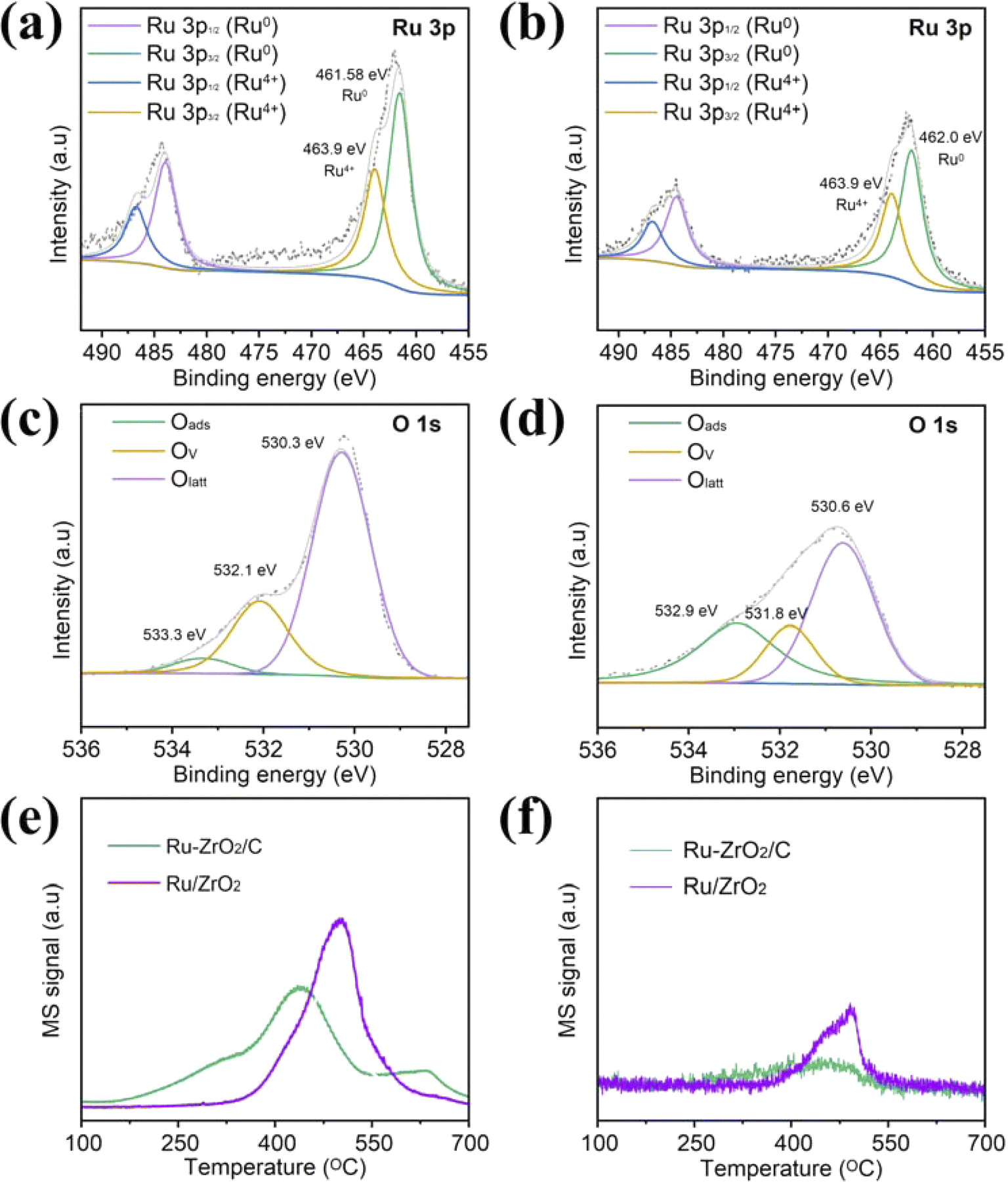 | ||
| Fig. 5 (a–d) Ru 3p and O 1s of Ru–ZrO2/C and Ru/ZrO2, respectively; (e and f) CO2-TPD and CH4-TPD profiles of Ru–ZrO2/C and Ru/ZrO2. | ||
| Samples | The binding energy of Ru | Binding energy of O | Molar ratios by XPS | ||||
|---|---|---|---|---|---|---|---|
| Ru0 | Ru4+ | Oads | OVs | Olatt | Ru0/Ru4+ | OVs/Olatt | |
| Ru–ZrO2/C | 461.6 | 463.9 | 533.3 | 532.1 | 530.3 | 1.62 | 0.36 |
| Ru/ZrO2 | 462.0 | 463.9 | 532.9 | 531.8 | 530.6 | 1.54 | 0.35 |
| Ru–ZrO2/C-3h | 462.1 | 464.8 | 533.5 | 532.1 | 530.4 | 2.46 | 0.37 |
The better adsorption capacity of the reactants facilitates more reactant molecules to participate in the reaction, while the better desorption capacity of the products accelerates the departure of the product molecules, and leaves more adsorption sites for the subsequent CO2 hydrogenation reaction. In this study, the CO2-TPD profile is obtained as shown in Fig. 5e. Ru–ZrO2/C shows a strong signal at the center of 460 °C and 663 °C, which is attributed to the medium-strength and strong basic sites, respectively. The peaks at around 663 °C can be attributed to the CO2 adsorption on the strong basic sites and surface oxygen vacancies.60 Beyond this, the CO2 desorption signal extends up to 700 °C due to the presence of strongly basic sites. The intensity of Ru–ZrO2/C is significantly higher than that of Ru/ZrO2, suggesting the presence of more CO2 adsorption active sites on Ru–ZrO2/C. More CO2 adsorption active sites can adsorb and activate more CO2 molecules and promote electron–CO2 interactions, thus favoring the formation of CH4.47 In addition, the CH4-TPD spectra of Ru–ZrO2/C show that the desorption of CH4 is lower than that of Ru/ZrO2 (Fig. 5f), which indicate that CH4 is less likely to be adsorbed on the surface of Ru–ZrO2/C than Ru/ZrO2. Therefore, CH4 as a product can be rapidly desorbed from the Ru–ZrO2/C surface and leave more active sites for adsorption and activation of CO2 molecules.47 This ultimately improves the catalytic performance of light-driven CO2 methanation.
In situ DRIFTS is performed under a continuous flow of the mixture gas (10% CO2, 40% H2, and 50% He) to identify the intermediates involved and to determine the CO2 reaction pathways. The intermediates appear in the infrared fingerprint region at 1200–1700, 1900–2500, and 3000–3050 cm−1, and the band assignments of the surface-activated species are shown in Table S2.† The in situ DRIFTS spectra of Ru–ZrO2/C at different temperatures are recorded after reaching reaction equilibrium under the same continuous flow reaction conditions as photothermal catalysis (Fig. 6a). The signals of the characteristic peaks increase dramatically with the increase in reaction temperature. After the introduction of the mixture gas at 250 °C, bands of bidentate carbonates (b-CO32−, 1581, 1542, and 1513 cm−1) are observed.61 With the temperature increasing from 250 to 400 °C, the signals of the important intermediates are enhanced in the bands at 1230, 1641, and 1900–2100 cm−1 belonging to COOH*, CH3O−, and linear CO, respectively. The characteristic bands at 1305 and 3016 cm−1 correspond to CH4, which gradually increases as the temperature increases from 250 °C to 400 °C. Meanwhile, similar peaks are observed on Ru–ZrO2/C without light, as shown in Fig. 6b. This indicates that photothermal and thermal CO2 hydrogenation follow a similar reaction pathway, which again suggests that the photo-generated electrons play a minor role in CO2 methanation and the reaction system is a light-driven thermocatalytic reduction reaction.62
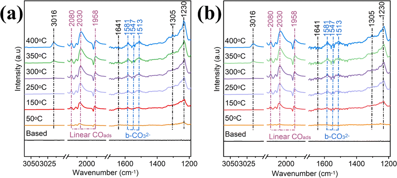 | ||
| Fig. 6 In situ DRIFTS spectra of Ru–ZrO2/C were measured under light (a) and without light (b) radiation with external heating. During the temperature-programmed reaction: a gas mixture (20 mL min−1) containing 10% CO2/40% H2/50% He was employed. | ||
Based on the above discussion, a photothermal catalytic reaction mechanism for CO2 reduction on Ru–ZrO2/C is proposed. The light-absorbing properties of ZrO2/C and the “nano-heater” effect of ruthenium nanoparticles convert light energy into heat energy through the photothermal effect under irradiation, thus triggering the catalytic CO2 methanation reaction. CO2 and H2 are adsorbed on the catalyst surface, H2 is dissociated into H atoms, and H atoms reduce the adsorbed CO2 and intermediate products on the catalyst surface. The adsorbed CO2 molecules are dissociated to produce the intermediate HCOO* (CO2 + O* → OCO2* + OH* → HCOO*),63 which generates CO intermediates and a small amount of H2O by the reverse water–gas reaction, and a small amount of CO signal escapes to be detected by the detector (CO2(g) + H2(g) → CO(g) + H2O(g)). Most of the intermediates such as CO*, H*, HCOO*, and hydroxyl groups are adsorbed on the surface of the catalyst and further react to produce CH4 (CO* + H* → HCOO* + H* → H3CO* + OH* → *CH4).64 This is confirmed by the in situ DRIFTS spectroscopic results, and it is finally converted to CH4 by the methanation reaction, which can be expressed as follows: CO2–CO–CH3O−–CH4.65
4 Conclusion
In summary, this work reports the successful construction of an efficient Ru–ZrO2/C catalyst via inert gas calcination treatment for photothermal CO2 methanation. The Ru–ZrO2/C catalysts simultaneously achieve a rCH4 of 504.1 mmol g−1 h−1 in a flow reaction with a selectivity of 98.9% under full-spectrum simulated illumination. Moreover, the catalytic performance of Ru–ZrO2/C remains essentially constant in the 24 hour stability test. The comprehensive characterization of the physical and chemical properties of the catalyst reveal the remarkable heat resistance, metal Ru, metal–support interaction and the good adsorption performance for CO2 synergistic promotion of the photothermal CO2 methanation reaction. Besides, better photothermal catalytic performance is obtained due to the light-absorbing properties of ZrO2/C and the “nano-heater” effect of the ruthenium nanoparticles. The above suggests that the ZrO2/C support has an important influence on the catalytic performance of the catalysts. This not only expands the application field of MOFs as precursors, but also provides a new idea for the construction of highly efficient loaded photothermal catalysts, and provides an effective guide for the design and synthesis of highly efficient photocatalysts for solar fuel production.Author contributions
Huiling Wang: conceptualization, data curation, formal analysis, investigation, methodology, resources, writing – original draft. Qiang Li: methodology, writing – review & editing. Jing Chen: conceptualization, writing – review & editing. Hongpeng Jia: conceptualization, supervision, writing – review & editing, project administration, funding acquisition.Conflicts of interest
The authors declare that they have no known competing financial interests or personal relationships that could have appeared to influence the work reported in this paper.Acknowledgements
This work was supported by the National Nature Science Foundation of China [No. 22376193 and 22176187]; the Science and Technology Planning Project of Xiamen [No. 3502Z20226022].References
- Y. Wei, K. Chen, J. Kang, W. Chen, X. Wang and X. Zhang, Eng, 2022, 14, 52–63 CrossRef CAS.
- Q. Liu, X. Yang, L. Li, S. Miao, Y. Li, Y. Li, X. Wang, Y. Huang and T. Zhang, Nat. Commun., 2017, 8, 1407 CrossRef PubMed.
- Y. Lou, F. jiang, W. Zhu, L. Wang, T. Yao, S. Wang, B. Yang, B. Yang, Y. Zhu and X. Liu, Appl. Catal., B, 2021, 291, 120122 CrossRef CAS.
- J. Wang, G. Li, Z. Li, C. Tang, Z. Feng, H. An, H. Liu, T. Liu and C. Li, Sci. Adv., 2017, 3, e1701290 CrossRef PubMed.
- W. Yue, Y. Li, W. Wei, J. Jiang, J. Caro and A. Huang, Angew. Chem., Int. Ed., 2021, 60, 18289–18294 CrossRef CAS PubMed.
- J. Ren, S. Ouyang, H. Xu, X. Meng, T. Wang, D. Wang and J. Ye, Adv. Energy Mater., 2017, 7, 1601657 CrossRef.
- W. Vrijburg, E. Moioli, W. Chen, M. Zhang, B. Terlingen, B. Zijlstra, I. Filot, A. Züttel, E. Pidko and E. Hensen, ACS Catal., 2019, 9, 7823–7839 CrossRef CAS.
- X. Jia, N. Rui, X. Hu and C. Liu, Appl. Catal., B, 2019, 244, 159–169 CrossRef CAS.
- Z. Li, J. Wang, Y. Qu, H. Liu, C. Tang, S. Miao, Z. Feng, H. An and C. Li, ACS Catal., 2017, 7, 8544–8548 CrossRef CAS.
- X. Li and Q. Zhu, EnergyChem, 2020, 2, 100033 CrossRef.
- H. Zhang, W. Tian, Y. Li, H. Sun, M. Tadéa and S. Wang, J. Mater. Chem. A, 2018, 6, 6265–6272 RSC.
- X. J. Meng, C. Niu, Q. Pang, J. Li, F. Liu, Z. Liu and L. Mai, Chem. Soc. Rev., 2020, 49, 3142 RSC.
- M. Li, X. Liu, Y. Che, H. Xing, F. Sun, W. Zhou and G. Zhu, Angew. Chem., Int. Ed., 2023, 62, e202308651 CrossRef CAS PubMed.
- W. Zhou, D. Huang, Y. Wu, J. Zhao, T. Wu, J. Zhang, D. Li, C. Sun, P. Feng and X. Bu, Angew. Chem., Int. Ed., 2019, 58, 4227–4231 CrossRef CAS PubMed.
- Y. Jia, Z. Xue, Y. Li and G. Li, Energy Environ. Mater., 2022, 5, 1084–1102 CrossRef CAS.
- X. Deng, J. Albero, L. Xu, H. García and Z. Li, Inorg. Chem., 2018, 57, 8276–8286 CrossRef CAS PubMed.
- X. Kong, T. He, J. Zhou, C. Zhao, T. Li, X. Wu, K. Wang and J. Li, Small, 2021, 17, 2005357 CrossRef CAS PubMed.
- Q. Mu, Y. Su, Z. Wei, H. Sun, Y. Lian, Y. Dong, P. Qi, Z. Deng and Y. Peng, J. Catal., 2021, 397, 128–136 CrossRef CAS.
- Z. Liu, L. Niu, X. Zong, L. An, D. Qu, X. Wang and Z. Sun, Appl. Catal., B, 2022, 313, 121439 CrossRef CAS.
- H. Ren, M. Tang, B. Guan, K. Wang, J. Yang, F. Wang, M. Wang, J. Shan, Z. Chen, D. Wei, H. Peng and Z. Liu, Adv. Mater., 2017, 29, 1702590 CrossRef PubMed.
- Y. Zhai, Y. Dou, D. Zhao, P. Fulvio, R. Mayes and S. Dai, Adv. Mater., 2011, 23, 4828–4850 CrossRef CAS PubMed.
- D. Chen, W. Shen, S. Wu, C. Chen, X. Luo and L. Guo, Nanoscale, 2016, 8, 7172–7179 RSC.
- Y. Kaneti, J. Tang, R. Salunkhe, X. Jiang, A. Yu, K. Wu and Y. Yamauchi, Adv. Mater., 2017, 29, 1604898 CrossRef PubMed.
- D. Chen, H. Sun, Y. Wang, H. Quan, Z. Ruan, Z. Ren and X. Luo, Appl. Surf. Sci., 2020, 507, 145054 CrossRef CAS.
- J. Yang, K. Li and J. Gu, ACS Mater. Lett., 2022, 4, 385–391 CrossRef CAS.
- B. Guan, L. Yu and X. Lou, J. Am. Chem. Soc., 2016, 138, 11306–11311 CrossRef CAS PubMed.
- Y. Lu, J. Lin, L. Wang, L. Zhang and C. Cai, Chem. Rev., 2020, 120, 4111–4140 CrossRef CAS PubMed.
- Y. Yan, G. Chen, P. She, G. Zhong, W. Yan, B. Y. Guan and Y. Yamauchi, Adv. Mater., 2020, 32, 2004654 CrossRef CAS PubMed.
- Y. Yang, J. Liu, F. Liu and D. Wu, Fuel, 2020, 276, 118093 CrossRef CAS.
- P. Panagiotopoulou, D. Kondarides and X. Verykios, Catal. Today, 2012, 181, 138–147 CrossRef CAS.
- B. Liu, X. Liu, J. Liu, C. Feng, Z. Li, C. Li, Y. Gong, L. Pan, S. Xu and C. Sun, Appl. Catal., B, 2018, 226, 234–241 CrossRef CAS.
- F. Vermoortele, B. Bueken, G. Bars, B. Voorde, M. Vandichel, K. Houthoofd, A. Vimont, M. Daturi, M. Waroquier, V. Speybroeck, C. Kirschhock and D. Vos, J. Am. Chem. Soc., 2013, 135, 11465–11468 CrossRef CAS PubMed.
- Z. Hao, J. Shen, S. Lin, X. Han, X. Chang, J. Liu, M. Li and X. Ma, Appl. Catal., B, 2021, 286, 119922 CrossRef CAS.
- C. Guo, Y. Tang, Z. Yang, T. Zhao, J. Liu, Y. Zhao and F. Wang, ACS Nano, 2023, 17, 23761–23771 CrossRef CAS PubMed.
- H. Jiang, L. Wang, H. Kaneko, R. Gu, G. Su, L. Li, J. Zhang, H. Song, F. Zhu, A. Yamaguchi, J. Xu, F. Liu, M. Miyauchi, W. Ding and M. Zhong, Nat. Catal., 2023, 6, 519–530 CrossRef CAS.
- A. Kim, D. P. Debecker, F. Devred, V. Dubois, C. Sanchez and C. Sassoye, Appl. Catal., B, 2018, 220, 615–625 CrossRef CAS.
- X. Chen, X. Chen, S. Cai, E. Yu, J. Chen and H. Jia, Appl. Surf. Sci., 2019, 475, 312–324 CrossRef CAS.
- M. Cai, Z. Wu, Z. Li, C. Li, S. Wang, K. Feng, M. Peng, W. Liu, L. He, X. Zhang, W. Sun, A. Tountas, S. Tang, A. Tavasoli, G. Ozin, L. Wang, A. Xu and A. Helmy, Nat. Energy, 2021, 6, 807–814 CrossRef CAS.
- K. Peng, J. Ye, H. Wang, H. Song, B. Deng, S. Song, Y. Wang, L. Zuo and J. Ye, Appl. Catal., B, 2023, 324, 122262 CrossRef CAS.
- L. Wang, Y. Dong, T. Yan, Z. Hu, F. Ali, D. Meira, P. Duchesne, J. Loh, C. Qiu, E. Storey, Y. Xu and W. Sun, Nat. Commun., 2020, 11, 2432 CrossRef CAS PubMed.
- X. Liu, C. Xing, F. Yang, Z. Liu, Y. Wang, T. Dong, L. Zhao, H. Liu and W. Zhou, Adv. Energy Mater., 2022, 12, 2201009 CrossRef CAS.
- M. Mũnoz, S. Gallego, J. Beltrán and J. Cerdá, Surf. Sci. Rep., 2006, 61, 303–344 CrossRef.
- J. Ren, F. Zeng, C. Mebrahtu, Z. Wang and R. Palkovits, J. Energy Chem., 2023, 86, 351–361 CrossRef CAS.
- Y. Jiang, T. Huang, H. Chou, L. Zhou, S. Lee, K. Wang and S. Dai, J. Mater. Chem. A, 2022, 10, 17730–17739 RSC.
- E. Z. Truszkiewicz, A. Bielecka, D. nski and A. Ostrowski, Int. J. Hydrogen Energy, 2023, 48, 24936–24950 CrossRef CAS.
- D. Méndez-Mateos, V. Barrio, J. Requies and J. Cambra, Catalysts, 2021, 11, 353 CrossRef.
- S. Cai, M. Zhang, J. Li, J. Chen and H. Jia, Sol. RRL, 2020, 5, 2000313 CrossRef.
- T. Dong, X. Liu, Z. Tang, H. Yuan, D. Jiang, Y. Wang, Z. Liu, X. Zhang, S. Huang, H. Liu, L. Zhao and W. Zhou, Appl. Catal., B, 2023, 326, 122176 CrossRef CAS.
- Y. Tang, T. Zhao, H. Han, Z. Yang, J. Liu, X. Wen and F. Wang, Adv. Sci., 2023, 10, 2300122 CrossRef CAS PubMed.
- Z. Wang, Y. Zhou, D. Liu, R. Qi, C. Xia, M. Li, B. You and B. Xia, Angew. Chem., Int. Ed., 2022, 61, e202200552 CrossRef CAS PubMed.
- A. Sato, D. Volanti, D. Meira, S. Damyanova, E. Longo and J. Bueno, J. Catal., 2013, 307, 1–17 CrossRef CAS.
- S. Yuan, P. Ma, Y. Yang, X. Shen, H. Pan, Z. Li, Y. Li and Y. Gao, Fuel, 2023, 335, 126855 CrossRef CAS.
- R. Ye, L. Ma, X. Hong, T. Reina, W. Luo, L. Kang, G. Feng, R. Zhang, M. Fan, R. Zhang and J. Liu, Angew. Chem., Int. Ed., 2024, 63, e202317669 CrossRef CAS PubMed.
- H. Ge, Y. Kuwahara, K. Kusu, Z. Bian and H. Yamashita, Appl. Catal., B, 2022, 317, 121734 CrossRef CAS.
- K. Zhang, C. Xu, X. Zhang, Z. Huang, Q. Pian, K. Che, X. Cui, Y. Hu and Y. Xuan, Small, 2023, 2308823 Search PubMed.
- T. Zhang, W. Wang, F. Gu, W. Xu, J. Zhang, Z. Li, T. Zhu, G. Xu, Z. Zhong and F. Su, Appl. Catal., B, 2022, 312, 121385 CrossRef CAS.
- S. Cheng, Z. Sun, K. H. Lim, A. Wibowo, T. Zhang, T. Du, L. Liu, H. Nguyen, G. Li, Z. Yin and S. Kawi, ACS Catal., 2023, 13, 7221–7229 CrossRef CAS.
- S. Cheng, Z. Sun, K. Lim, K. Liu, A. Wibowo, T. Du, L. Liu, H. Nguyen, G. Li, Z. Yin and S. Kawi, Appl. Catal., B, 2024, 343, 123583 CrossRef CAS.
- M. Kim, S. Kim, J. Park, S. Lee, I. Jang, S. Kim, C. Lee, O. Kwon, H. Ham, J. Hupp, N. Jung, S. Yoo and D. Whang, Adv. Funct. Mater., 2023, 33, 2300673 CrossRef CAS.
- Y. Yang, Z. Chai, X. Qin, Z. Zhang, A. Muhetaer, C. Wang, H. Huang, C. Yang, D. Ma, Q. Li and D. Xu, Angew. Chem., Int. Ed., 2022, 61, e202200567 CrossRef CAS PubMed.
- A. Li, Q. Cao, G. Zhou, B. Schmidt, W. Zhu, X. Yuan, H. Huo, J. Gong and M. Antonietti, Angew. Chem., Int. Ed., 2019, 58, 14549–14555 CrossRef CAS PubMed.
- F. Zhang, Y. Li, M. Qi, Y. Yamada, M. Anpo, Z. Tang and Y. Xu, Chem Catal., 2021, 1, 272–297 CrossRef CAS.
- F. He, J. Zhuang, B. Lu, X. Liu, J. Zhang, F. Gu, M. Zhu, J. Xu, Z. Zhong, G. Xu and F. Su, Appl. Catal., B, 2021, 293, 120218 CrossRef CAS.
- S. Kattel, P. Liu and J. Chen, J. Am. Chem. Soc., 2017, 139, 9739–9754 CrossRef CAS PubMed.
- P. Du, G. Deng, Z. Li, J. Sun, L. Wang, Y. Yang, J. Wang, Y. Li, X. Xu, Y. Zhang, W. Liu, G. Liu, Z. Zou and Z. Li, J. Mater. Sci. Technol., 2024, 189, 203–210 CrossRef.
Footnote |
| † Electronic supplementary information (ESI) available. See DOI: https://doi.org/10.1039/d4ta01821d |
| This journal is © The Royal Society of Chemistry 2024 |