
 Open Access Article
 This Open Access Article is licensed under a Creative Commons Attribution-Non Commercial 3.0 Unported Licence
Fe-doped α-MnO2/rGO cathode material for zinc ion batteries with long lifespan and high areal capacity†
Qiang
Zhang
a,
Hefei
Fan
a,
Qianfeng
Liu
a,
Yangga
Wu
b and
Erdong
Wang
 *a
*a
aDivision of Fuel Cell & Battery, Dalian National Laboratory for Clean Energy, Dalian Institute of Chemical Physics, Chinese Academy of Sciences, Dalian 116023, China. E-mail: edwang@dicp.ac.cn
bEnergy Administration of Inner Mongolia Autonomous Region, China
First published on 1st March 2024
Abstract
Currently, research interest in aqueous zinc ion batteries (ZIBs) has surged throughout the world owing to their merits of high theoretical energy density, high safety and low cost. However, the lack of suitable cathode materials with high energy density and cycling stability has severely restricted the further development and practical application of ZIBs. Herein, we propose a facile Fe heteroatom doping and rGO external coating modification strategy for preparing an Fe-doped α-MnO2/rGO cathode material with excellent kinetic performance and structural stability for ZIBs. The introduction of heterogeneous Fe increased carrier concentration and induced Mn-defects in the α-MnO2 lattice, which not only improved electronic conductivity, but also attenuated electrostatic interactions during the process of Zn2+ ion insertion/extraction. Furthermore, the coated rGO layer with a thickness of about 4 nm significantly suppressed the dissolution of Mn2+ ions and volume expansion during cycles. Consequently, it delivered a high specific capacity of 167.7 mA h g−1 at 1 A g−1 after 2000 cycles and an excellent rate capacity of 62.5 mA h g−1 at 15 A g−1. Encouragingly, an imposing areal capacity of 32.8 mA h cm−2 and a specific capacity of 164.2 mA h g−1 were observed at 0.05C (1C = 308 mA h g−1) for a highly active material loading of 200 mg cm−2.
Introduction
Aqueous zinc-ion batteries (ZIBs) have developed into a promising energy storage battery system with an inherent nature of high safety, high energy density and environmental friendliness.1–3 As is well known, metal Zn anodes have the advantages of low redox potential (−0.76 V vs. the standard hydrogen electrode (SHE)), high theoretical capacity (820 mA h g−1, and 5855 mA h cm−3), high compatibility/stability, and abundant natural reserves.4,5 Besides, mild aqueous electrolytes are non-flammable and have higher conductivity and lower cost compared with organic electrolytes.6–8 Although ZIBs are considered one of the most effective ways to utilize zinc metal resources and are available to meet the growing market demands for high-performance energy storage devices at a low cost, the lack of suitable excellent cathode materials for the storage of Zn ions has seriously limited the further development of ZIBs.9,10Compared with conventional materials analogous to Prussian blue (low capacities, <100 mA h g−1) and burgeoning vanadium-based materials (having low operating voltages, ∼0.6–0.7 V versus Zn),11–15 alpha manganese oxide (α-MnO2) has been receiving more attention because of its high theoretical capacity of 308 mA h g−1 (only considering the insertion of Zn2+ ions) and higher working voltage (∼1.3–1.4 V versus Zn).16–18 Unfortunately, it delivers poor kinetic performance due to its low electronic conductivity of 10−4 to 10−3 S m−1 and the strong electrostatic interactions between Zn2+ ions and its host lattice.6,19 Moreover, its poor cycling stability, which is due to the dissolution of Mn2+ ions in aqueous electrolytes, and the structure collapse during cycles are troublesome.20–22 To date, the most conventional modification means to overcome these deficiencies are the formation of composites with highly conductive matrix materials such as graphene and its derivatives6,23,24 and surface modification using conducting polymers.16,25 Besides these external splicing modifications, doping heterogeneous atoms such as Co, Ni, and Al, into MnO2 lattice is another effective approach to enhance its electronic conductivity, with cation-deficiency tending to change its electronic structure.20,26,27 Moreover, cationic vacancies can attenuate the electrostatic interaction between a host lattice and multivalent ions and further facilitate multivalent ion insertion from the host.28,29
Herein, we synthesized an Fe-doped α-MnO2/rGO composite, in which parts of Mn sites are substituted by Fe dopants. The created Mn vacancy induces crystal defects and attenuates electrostatic interaction during Zn2+ ion insertion/extraction, as well as the increased carrier concentration enhances its electronic conductivity. Additionally, benefitting from the balancing of surplus protonation by appropriate Fe3+ ions incorporated into the α-MnO2 framework, its tunnel structures become more stable. Simultaneously, the hybrid rGO layer further enhances its electronic conductivity and structural stability as the dissolution and volume expansion of Mn2+ ions during cycles are suppressed. As a cathode material for ZIBs, it exhibits a prominent capacity of 167.7 mA h g−1 after 2000 cycles at 1 A g−1, long-term cyclability of 72.2 mA h g−1 after 10![[thin space (1/6-em)]](https://www.rsc.org/images/entities/char_2009.gif) 000 cycles at 10 A g−1, and superior rate capability of 62.5 mA h g−1 at 15 A g−1. More encouragingly, it delivers an imposing areal capacity of 32.8 mA h cm−2 and a specific capacity of 164.2 mA h g−1 at 0.05C with a high loading of the active material of about 200 mg cm−2 in a pouch battery.
000 cycles at 10 A g−1, and superior rate capability of 62.5 mA h g−1 at 15 A g−1. More encouragingly, it delivers an imposing areal capacity of 32.8 mA h cm−2 and a specific capacity of 164.2 mA h g−1 at 0.05C with a high loading of the active material of about 200 mg cm−2 in a pouch battery.
Experimental
Preparation of samples
The α-MnO2-based materials were synthesized through a hydrothermal synthesis method. GO was prepared from natural graphite powders by a modified Hummers' method.30,31 Typically, 0.507 g MnSO4·H2O and 0.0485 g Fe(NO3)3·9H2O were added to 50 mL deionized water with 1 mmol H2SO4 dissolved, accompanied by stirring for 5 min. Then, 0.316 g KMnO4 was dispersed into 20 mL deionized water and then added dropwise to the mixed solution mentioned above within a few minutes under vigorous stirring. Afterwards, the mixed solution was transferred into a 100 mL Teflon-lined stainless-steel autoclave and maintained at 120 °C for 12 h. After natural cooling, the Fe-doped α-MnO2 product was washed thoroughly with ethanol and water several times via centrifugation. Subsequently, the prepared Fe-doped α-MnO2 was redispersed into 80 mL deionized water and 10 mg GO was added under stirring. The mixture was then sealed in a 100 mL Teflon-lined autoclave for 12 h at 120 °C. Finally, the Fe-doped α-MnO2/rGO was collected by centrifugation after washing with water several times followed by vacuum drying at 60 °C for 10 h. For comparison, the α-MnO2 material was also synthesized by the same method without adding Fe and GO. The flexible porous zinc powder anode was prepared using the scratch-coating method. Specifically, the used zinc powder, poly(vinylidene fluoride) (PVDF), carboxymethylcellulose sodium (CMC-Na), Bi2O3, SnO2 and NaHCO3 were dissolved in N-methylpyrrolidone (NMP) solvent dispersant with a weight ratio of 87:5:1:1:1:5 under stirring. After the formation of an even slurry, the solution was scratch-coated onto the surface of a glass plate and subsequently dried at 60 °C in a vacuum oven for 2 h to obtain the needed flexible porous zinc powder anode.
Characterization
The crystalline characteristics of the Fe-doped α-MnO2/rGO, Fe-doped α-MnO2 and α-MnO2 materials were characterized using X-ray diffraction (XRD) with 2θ angle ranging from 10° to 80° at a scan rate of 6° min−1. The morphological features of the materials were determined by scanning electronic microscopy (SEM), transmission electron microscopy (TEM) and high-resolution TEM (HRTEM), which were carried out using JSM-7500F (5 kV) and JEM-2100F (JEOL, 200 kV) instruments. The carbon contents were analysed using a thermogravimetric analyzer (TGA, NETZSCH STA 449F3) under an air atmosphere, and the temperature range was from room temperature to 800 °C with a heating rate of 10 °C min−1. X-ray photoelectron spectrometer (XPS) analyses were performed using an ESCALAB 250 instrument.DFT calculation
To accurately illustrate the effects of Fe doping on the electronic conductivity of α-MnO2, the CASTEP code based on the density functional theory (DFT) framework was performed using the Materials Studio software. Perdew–Burke–Ernzerhof (PBE) parameters, as well as generalized gradient approximation (GGA), were adopted to depict the exchange-correlation energy. The DFT + U was used to correct the van der Waals interactions.32,33 Pointedly, a 2 × 1 × 3 supercell (144 atoms) was established with the Fe doping concentration of 2.08% (Fig. 1a); a 600 eV cutoff energy and Monkhorst–Pack meshes with 1 × 1 × 2 were employed.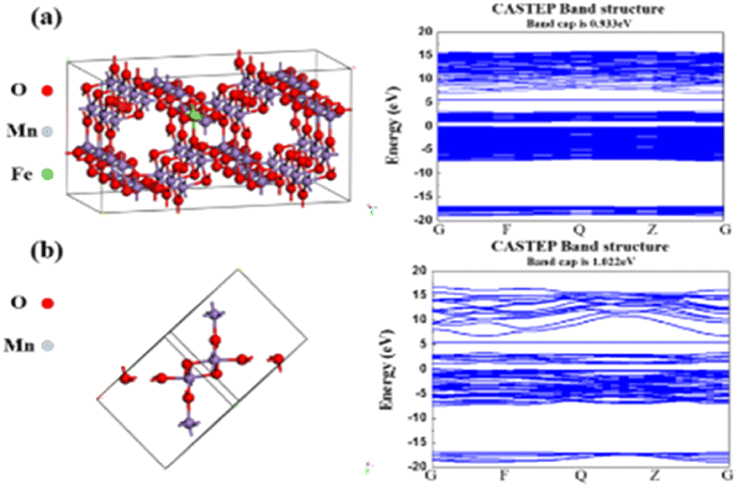 | ||
| Fig. 1 The calculated electronic properties of (a) Fe-doped α-MnO2 and (b) α-MnO2. | ||
Electrochemical measurements
2032-type coin cells and soft package cells were assembled to estimate the electrochemical performances of the Fe-doped α-MnO2/rGO, Fe-doped α-MnO2 and α-MnO2 materials. The active material, acetylene black and poly(vinylidene fluoride) (PVDF) were added to the N-methylpyrrolidone (NMP) solvent dispersant with a weight ratio of 8:1:1 to prepare the cathode slurries, respectively. The positive electrodes were prepared by coating the slurries onto nickel foams and drying them at 60 °C for 12 h in a vacuum. The active material mass loading of positive electrodes was about 2 mg cm−2 and the thickness was about 80 μm. The Zn foil (0.05 mm) and prepared flexible porous zinc powder anode were used as the counter electrodes, respectively. A Whatman glass fiber (GF/C) was adopted as the separator to assemble the cells, and a solution of 2 M ZnSO4·7H2O with 0.2 M MnSO4·H2O additive was employed as the electrolyte. A LAND-CT2001A battery test system was used to test the charge–discharge curves in a voltage range of 1.0–1.8 V. The specific capacities at different current densities were calculated based on the mass of active materials. Cyclic voltammetry (CV) curves were obtained in the voltage range of 1.0–1.8 V at a scan rate of 1 mV s−1. The electrochemical impedance spectra (EIS) were obtained in the frequency range of 0.1 Hz to 1 MHz with a 5 mV amplitude. The CV and EIS measurements were performed on a CHI660E electrochemical workstation.
Results and discussion
The synthesis and mechanism of the Fe-doped α-MnO2/rGO are described in Scheme 1. As mentioned before, the Fe-doped α-MnO2 precursor was generated by the reaction of MnSO4·H2O and KMnO4, during which the introduced heterogeneous atoms, Fe3+, easily occupied partial sites of Mn4+ since they have the same [MO6] octahedron structure and similar atomic radii (Fe3+ ∼63 pm, Mn4+ ∼53 pm).20,34,35 On the one hand, the number of holes in the valence band of α-MnO2 increased due to the incorporation of Fe3+ as an acceptor atom, thereby enhancing its electronic conductivity.20,34 As the density functional theory (DFT) calculation results demonstrated in Fig. 1, the Fe-doped α-MnO2 had a lower band gap of 0.933 eV (Fig. 1a) than pure α-MnO2 1.022 eV (Fig. 1b), indicating that its electronic conductivity was improved. On the other hand, the induced Mn vacancies and crystal defects by the aliovalent Fe substitution attenuated the electrostatic interactions between Zn2+ ions and the α-MnO2 host, facilitating the insertion/extraction of Zn2+ ions.28 The poor cycle stability of pure α-MnO2 resulted from the Mn2+ dissolution and structural collapse during cycles, and therefore, the coating method with reduced graphene oxide (rGO), which has excellent electronic conductivity and a large specific surface area, was adopted.6,36 In the coating process, the pre-synthesized Fe-doped α-MnO2 was attached to the surface of rGO sheets by the hydrogen bonds between [MnO6] octahedrons and functional groups on the surface of rGO sheets, and the rGO coating layer was formed after the subsequent hydrothermal reaction.6,23 Specifically, the coated rGO layer can alleviate the volume expansion when Zn2+ ions are inserted, and inhibit the dissolution of Mn2+ ions by the adsorption effect of its rich oxygen-containing functional groups.6,37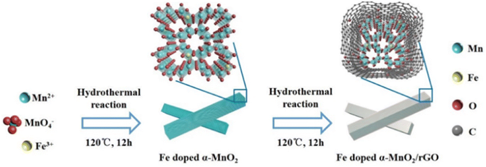 | ||
| Scheme 1 The synthesis of the Fe-doped α-MnO2/rGO material. | ||
The XRD patterns of the synthesized α-MnO2-based materials were determined to reveal their crystal structures (Fig. 2a). The main peaks with 2θ positions at 12.88°, 18.12°, 26.18°, 28.72°, 37.74°, 41.80° and 60.30° can be indexed to the (110), (200), (310), (211), (301), (411) and (521) lattice planes of the α-MnO2 (JCPDS No. 44-0141), implying the presence of α-MnO2 in the composites.20,38 The intensity of the diffraction peaks became slightly weaker with the Fe doping and rGO coating, indicating that the crystallinity of the composite had deteriorated.39 Notably, no characteristic peaks of iron compounds appeared in the XRD patterns, manifesting that the incorporated Fe did not exist as a mixture.40 The tiny peak shifting to the left side after the incorporation of Fe was caused by the slight crystal expansion.20 Interestingly, the Fe-doped α-MnO2/rGO nanowires were stacked like cotton wool with lengths of 0.5–2 μm (Fig. 2b), and the accompanying EDS images of O, Mn and Fe elements revealed the uniform distribution of these elements in the composite (Fig. 2c). Combined with thermogravimetric analyzer (TGA) results in Fig. 2d, the total carbon content in Fe-doped α-MnO2/rGO was determined to be 3.2%. The HRTEM (Fig. 2e–f) and EDS (Fig. S1a†) images further imply that the Fe-doped α-MnO2/rGO nanowires had a diameter of about 30–32 nm and the uniform distribution of the doped Fe element. The rGO layer with a thickness of approximately 4 nm was coated on the edge of the nanowire (Fig. 2e), giving it better structural stability, which can alleviate volume expansion and inhibit Mn2+ ion dissolution during cycles.6,36 Moreover, the diameter of the Fe-doped α-MnO2 (about 24 nm, Fig. 2g) was much smaller than the pure α-MnO2 (about 48 nm, Fig. 2h and S1b†), which is consistent with the broadening of its diffraction peaks in the XRD patterns (Fig. 2a). Similar to previous reports, heterogeneous element doping can narrow material particle size, thereby enhancing material cycle stability.36,41 Additionally, the selected area electron diffraction (SAED) pattern (embedded in Fig. 2f–h) exhibited the single-crystalline nature of the three α-MnO2-based materials, and the lattice spacings of 0.49 nm were found, which matched well with the (200) crystal plane of α-MnO2.20
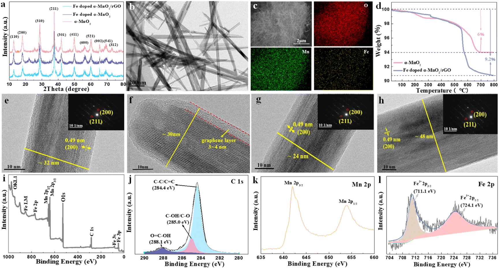 | ||
| Fig. 2 (a) XRD patterns of the synthesized α-MnO2, Fe-doped α-MnO2 and Fe-doped α-MnO2/rGO. TEM (b) and EDS (c) images of Fe-doped α-MnO2/rGO. (d) The TGA curves of Fe-doped α-MnO2/rGO and α-MnO2. HRTEM images of Fe-doped α-MnO2/rGO (e and f), Fe-doped α-MnO2 (g) and α-MnO2 (h) with related SAED patterns. (i) The survey spectra and (j) the fine spectra of C 1s; (k) Mn 2p peaks and (l) Fe 2p peaks of Fe-doped α-MnO2/rGO. | ||
The surface chemical compositions of Fe-doped α-MnO2/rGO were analyzed by XPS measurement and the results are presented in Fig. 2i–l. The XPS survey spectral analysis (Fig. 2i) revealed the existence of C, O, Mn, and Fe elements. The fine spectra of C 1s (Fig. 2j) further confirmed the sp2 bonded carbon at 284.4 eV (C–C/C![[double bond, length as m-dash]](https://www.rsc.org/images/entities/char_e001.gif) C), the epoxy at 285 eV (C–OH/C–O) and the carbonyls at 288.1 eV (HO–CO).36,42 The abundant oxygen-containing functional groups can inhibit the dissolution of Mn2+ ions due to the adsorption effect.6,36 The formation of α-MnO2 was verified by the two dominant peaks at 642.2 and 654.0 eV with a spin-energy separation of 11.8 eV observed in the Mn 2p spectrum (Fig. 2k), which correspond to Mn 2p3/2 and Mn 2p1/2.43,44 Undoubtedly, the existence of Fe3+ was determined by the Fe 2p spectrum (Fig. 2l) with the peaks of Fe3+ 2p3/2 and Fe3+ 2p1/2 located at 711.1 and 724.1 eV, respectively.45 It was concluded that Fe3+ ions were incorporated into the crystal lattice of α-MnO2, given that the peaks of the iron compounds were not detected in the XRD analysis.
C), the epoxy at 285 eV (C–OH/C–O) and the carbonyls at 288.1 eV (HO–CO).36,42 The abundant oxygen-containing functional groups can inhibit the dissolution of Mn2+ ions due to the adsorption effect.6,36 The formation of α-MnO2 was verified by the two dominant peaks at 642.2 and 654.0 eV with a spin-energy separation of 11.8 eV observed in the Mn 2p spectrum (Fig. 2k), which correspond to Mn 2p3/2 and Mn 2p1/2.43,44 Undoubtedly, the existence of Fe3+ was determined by the Fe 2p spectrum (Fig. 2l) with the peaks of Fe3+ 2p3/2 and Fe3+ 2p1/2 located at 711.1 and 724.1 eV, respectively.45 It was concluded that Fe3+ ions were incorporated into the crystal lattice of α-MnO2, given that the peaks of the iron compounds were not detected in the XRD analysis.
To demonstrate the advantages of the α-MnO2-based materials, we evaluated their electrochemical performances as cathode materials in ZIBs. CV measurement was carried out between 1.0 and 1.8 V with a scan rate of 0.5 mV s−1 to investigate the electrochemical behavior of Fe-doped α-MnO2/rGO and α-MnO2 materials, and the CV curves for the first four cycles are presented in Fig. 3a and S2.† A pair of reduction/oxidation peaks appeared at 1.08/1.62 V in the first cycle curve and disappeared in the subsequent cycles, corresponding to the phase transition of α-MnO2 during the first discharge process.16 In the following cycles, two pairs of reduction/oxidation peaks located at 1.23/1.35 V and 1.60/1.64 V appeared, which are related to the different insertion/extraction mechanisms of H+ and/or Zn2+ ions, respectively.16 Additionally, the 2nd, 3rd and 4th curves were almost coincident, implying that these related electrochemical reactions have good reversibility. α-MnO2 material (Fig. S2†) had similar electrochemical reactions to Fe-doped α-MnO2/rGO.
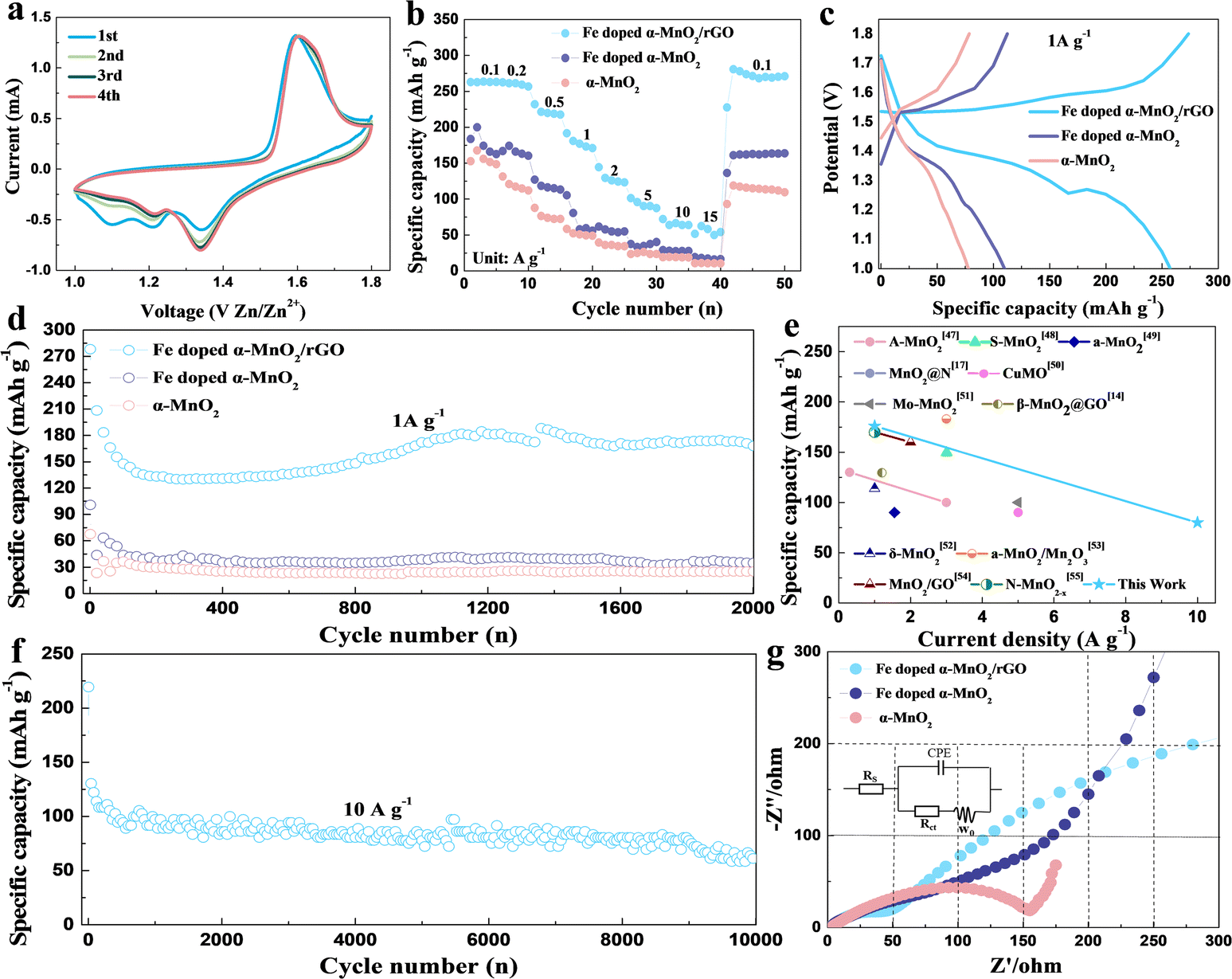 | ||
| Fig. 3 (a) CV curves of Fe-doped α-MnO2/rGO. (b) Rate capacities of the α-MnO2, Fe-doped α-MnO2 and Fe-doped α-MnO2/rGO ranging from 0.1 A g−1 to 15 A g−1, and (c) the corresponding galvanostatic discharge curves at 1 A g−1. The long-term discharge plots at 1 A g−1 (d) and 10 A g−1 (f). (e) The corresponding performance comparison image of MnO2-based material in ZIBs. (g) The Nyquist plots and the equivalent electrode circuit (inserted) of the materials. | ||
The rate capacities, which range from 0.1 A g−1 to 15 A g−1, can greatly reflect the excellent electronic conductivity and structural stability of the Fe-doped α-MnO2/rGO material (Fig. 3b). The Fe-doped α-MnO2/rGO delivered capacities of 263.5, 259.3, 232.0, 191.7, 144.4, 101.4, 72.2 and 62.5 mA h g−1 at 0.1, 0.2, 0.5, 1, 2, 5, 10, 15 A g−1, which are much higher than Fe-doped α-MnO2 and α-MnO2 at each step, respectively. Notably, it is capable of continuous discharge at 15 A g−1, and when the current is adjusted back to 0.1 A g−1, the discharge capacity can return to 268.2 mA h g−1, which is close to the initial level at 0.1 A g−1, implying that the structure of Fe-doped α-MnO2/rGO remains stable during the rapid discharge process. Moreover, benefiting from the improvement in the electronic conductivity and kinetic performance of Fe doping, the Fe-doped α-MnO2 electrode demonstrated a better rate discharge performance than α-MnO2.
The voltage platforms of the α-MnO2-based materials at a current density of 1 A g−1 were also analyzed and the results are shown in Fig. 3c. Distinctly, there are two high-voltage platforms, 1.38 and 1.29 V, for the Fe-doped α-MnO2/rGO electrode with a turning point at about 1.3 V dividing the voltage platform into two parts. Interestingly, the part higher than 1.3 V has a slower capacity decay trend than the lower 1.3 V part. Comparatively, Fe-doped α-MnO2 and α-MnO2 have lower voltage platforms due to their inferior electronic conductivity.
Fig. 3d displays the discharge capacity curves of the α-MnO2-based materials measured at a current density of 1 A g−1 between 1.0 and 1.8 V. The initial discharge capacities of 278.2, 100.9 and 67.7 mA h g−1 of the Fe-doped α-MnO2/rGO, Fe-doped α-MnO2 and α-MnO2 are exhibited. For the Fe-doped α-MnO2/rGO electrode, the specific capacity was stabilized to about 140 mA h g−1 in the first 400 cycles and gradually increased slightly in the subsequent cycles. As reported in similar reports, a reasonable explanation is that the electrode will undergo an activation process in the initial several cycles, the electrodes are gradually wetted by electrolyte as the cycle progresses, causing a decrease in electrode polarization.4,6 After 2000 cycles, the capacities of 25.1 and 34.4 mA h g−1 of α-MnO2 and Fe-doped α-MnO2 were maintained, respectively. Better electronic conductivity and weaker electrostatic interactions between the host lattice and Zn2+ ions were observed for Fe-doped α-MnO2 since Fe doping is the most likely reason for its better performance.28,32 Exhilaratingly, the highest capacity of 167.7 mA h g−1 for Fe-doped α-MnO2/rGO was obtained after 2000 cycles, which is one of the highest capacities of ZIBs (Fig. 3e and Table S1†). The reasons for the maintained high capacity caused by rGO coating can be summarized as follows. On the one hand, the electronic conductivity of the composite could be further enhanced, which was confirmed by the later EIS test with a lower Rct value of 34.9 Ω for the Fe-doped α-MnO2/rGO electrode than the Rct value of 65.7 Ω for the Fe-doped α-MnO2 electrode (Fig. 3g).46 On the other hand, its structural stability was enhanced, since the coated rGO can allow volume expansion and inhibit the dissolution of Mn2+ ions.6,36 To further evaluate the cyclic stability of the α-MnO2-based materials under high current density, charge–discharge cycles were tested at 10 A g−1 and the results are shown in Fig. 3f. The optimal 72.2 mA h g−1 in ZIBs14,17,47–55 (Fig. 3e) was maintained after 10000 cycles for Fe-doped α-MnO2/rGO, and Fe-doped α-MnO2 and α-MnO2 electrodes cannot cycle at such high current density.
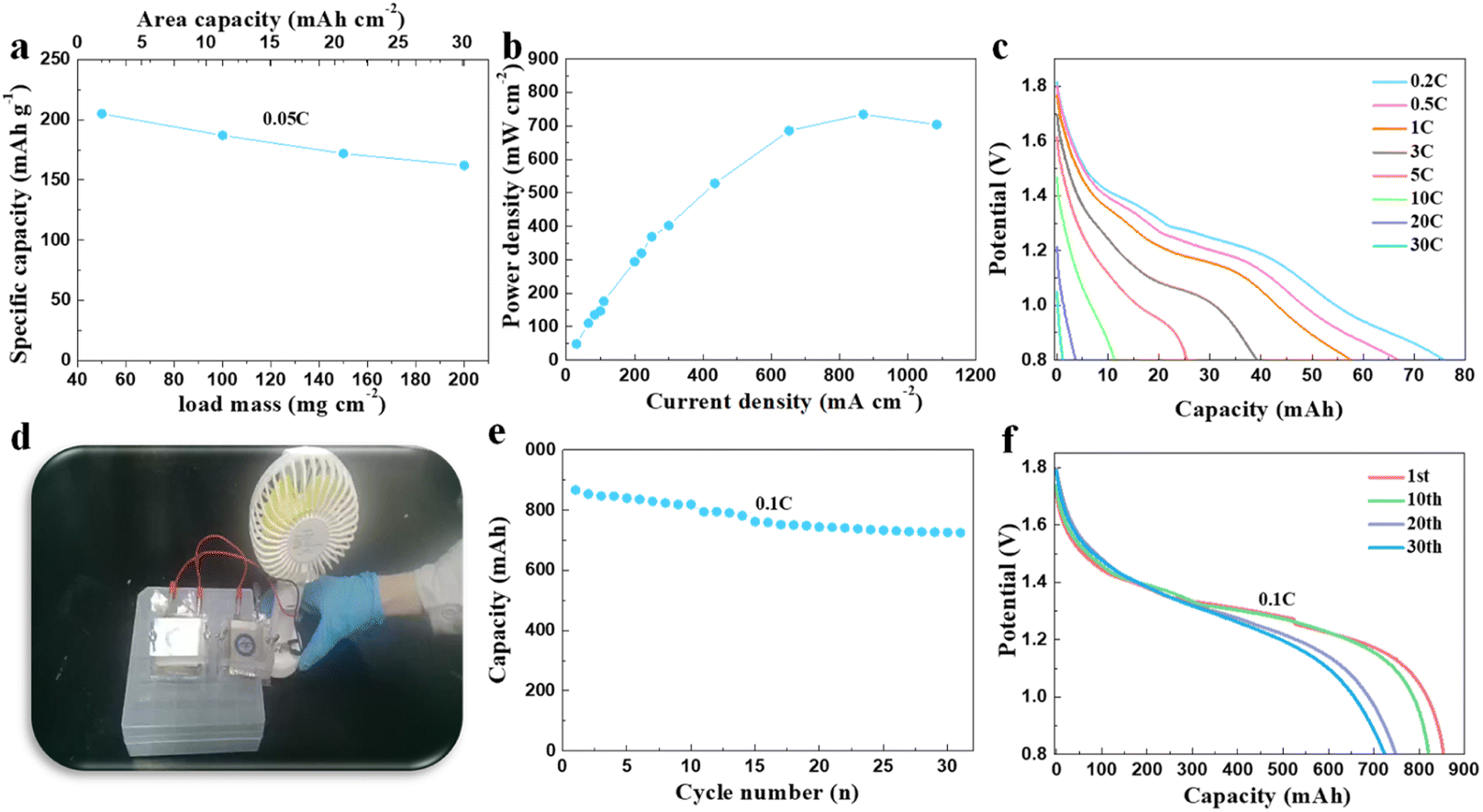
The systematic measuring of the material in high mass loading conditions was carried out. Based on its excellent electronic conductivity, the synthesized Fe-doped α-MnO2/rGO electrode showed specific capacities of 205.0, 187.0, 172.0 and 164.2 mA h g−1 at 0.05C (1C = 308 mA h g−1) under the conditions of 50, 100, 150 and 200 mg cm−2 active substance loading (Fig. 4a). Correspondingly, the highest area capacity of 32.8 mA h cm−2 was obtained, which never appeared in other reports related to MnO2-based materials for (lean solution) ZIBs. Notably, the related power density at 200 mg cm−2 under different current densities was also tested, and an amazing power density of 734.1 mW cm−2 at 870 mA cm−2 (Fig. 4b) was finally demonstrated. We also assembled a pouch battery with a theoretical capacity of 100 mA h using Fe-doped α-MnO2/rGO as the cathode active material under a high mass loading of 180 mg cm−2 with a thickness of about 220 μm. Delightfully, it exhibited an areal capacity of 75.9 mA h at 0.2C (Fig. 4c) and could discharge even under a high current density of 30C. Commercial portable fans (4.5 W) can be easily driven by two connected batteries in series with 200 mA h (Fig. 4d and video S1†). The battery is also extraordinarily safe and reliable even when struck (video S2†) and can stably drive an electric toy car (video S3†). We also designed and assembled an 800 mA h pouch battery, simulating a commercial battery with an areal capacity of 20 mA h cm−2, with an active material mass loading of about 114 mg cm−2 and a thickness of about 170 μm. The adopted capacity ratio between positive and negative electrodes was 1:2. To solve the short lifespan of the zinc foil anode due to dendrite growth, we designed and prepared a flexible porous zinc powder anode mentioned in the experimental section as an alternative, which delivered 1820 h cycle life at 1 mA cm−2 and 1 mA h cm−2 (Fig. S3†). Inspiringly, the assembled pouch battery demonstrated a considerable energy density of 61 W h kg−1 (calculated for all parts of the battery) at 0.1C and for 31 cycles with a capacity retention rate of 85.9% (Fig. 4e and f), which is valuable commercially. Moreover, the assembled pouch battery with Fe-doped α-MnO2/rGO and flexible porous zinc powder anode as cathode and anode (theoretical capacity 100 mA h) was also subjected to storage performance testing. After 760 h, the open circuit voltage of the battery was only reduced by 22.9 mV (Fig. S4a†), and its capacity retention rate even reached an exciting 95.2% at 0.1C (Fig. S4b†). Undoubtedly, the synthesized Fe-doped α-MnO2/rGO has bright application prospects.
 | ||
| Fig. 4 (a) The discharge capacity of Fe-doped α-MnO2/rGO under high mass loadings ranging from 50 mg cm−2 to 200 mg cm−2 at 0.05C with the corresponding areal capacity. (b) The power density curve of Fe-doped α-MnO2/rGO under high mass loading. (c) The rate performance of the assembled pouch battery with a theoretical capacity of 100 mA h using Fe-doped α-MnO2/rGO as the cathode active material under a high mass loading of 180 mg cm−2. (d) The digital image of the commercial portable fans (4.5 W)-driven batteries by two connected assembled pouch batteries in series with 200 mA h. (e) The discharge curve of the assembled pouch battery with a theoretical capacity of 800 mA h at 0.1C and (f) the corresponding galvanostatic discharge profiles. | ||
Conclusions
In summary, a novel cathode material, Fe-doped α-MnO2/rGO, for ZIBs with excellent kinetic performance and cycle stability was successfully designed and synthesized. Mn defects were induced by heterogeneous Fe doping to attenuate the electrostatic interaction between the α-MnO2 lattice and Zn2+ ions, and carrier concentration was increased to improve its electronic conductivity. Its structural stability was also enhanced by rGO coating since the volume expansion and Mn2+ dissolution were suppressed. As a cathode material for ZIBs, it exhibited a prominent capacity of 167.7 mA h g−1 at 1 A g−1 after 2000 cycles, an imposing areal capacity of 32.8 mA h cm−2 and a specific capacity of 164.2 mA h g−1 at 0.05C under a high active material mass loading of 200 mg cm−2. Besides, it can discharge continuously at 15 A g−1 in rate cycle testing and possesses a high power density of 734.1 mW cm−2 under mass loading of 200 mg cm−2. These excellent performances in both low and high active substance loading conditions will undoubtedly push the practical application of the Fe-doped α-MnO2/rGO material in ZIBs.Author contributions
Q. Zhang: conceptualization, methodology, investigation, writing –original draft preparation, writing – review & editing. H. Fan: methodology. Q. Liu: methodology, funding acquisition. Y. Wu: methodology. E. Wang: funding acquisition, project administration.Conflicts of interest
There are no conflicts to declare.Acknowledgements
The authors acknowledge financial support from the National Natural Science Foundation of China (22202203), the Strategic Priority Research Program of the Chinese Academy of Sciences (XDA 22010601), and the National Natural Science Foundation of China (grant no. 22005299).References
- S. Z. Deng, B. G. Xu, X. L. Liu, C. W. Kan and T. D. Chen, Chem. Eng. J., 2023, 475, 146098 CrossRef CAS.
- S. H. Wang, G. X. Liu, W. Wan, X. Y. Li, J. Li and C. Wang, Adv. Mater., 2023, 35, 2306546 Search PubMed.
- Z. Y. Zheng, S. Y. Yan, Y. F. Zhang, X. P. Zhang, J. Zhou, J. L. Ye and Y. S. Zhu, Chem. Eng. J., 2023, 475, 146314 CrossRef CAS.
- C. Y. Zhu, G. Z. Fang, J. Zhou, J. H. Guo, Z. Q. Wang, C. Wang, J. Y. Li, Y. Tang and S. Q. Liang, J. Mater. Chem. A, 2018, 6, 9677–9683 RSC.
- Y. H. Meng, L. Q. Wang, J. X. Zeng, B. Hu, J. M. Kang, Y. X. Zhang, J. J. Zhang, Z. D. Zhao, L. Zhang and H. B. Lu, Chem. Eng. J., 2023, 474, 145987 CrossRef CAS.
- B. K. Wu, G. B. Zhang, M. Y. Yan, T. F. Xiong, P. He, L. He, X. Xu and L. Q. Mai, Small, 2018, 14, 1703850 CrossRef PubMed.
- X. S. Xie, J. J. Li, Z. Y. Xing, B. G. Lu, S. Q. Liang and J. Zhou, Natl. Sci. Rev., 2023, 10, nwac281 CrossRef CAS PubMed.
- K. M. Su, X. Y. Zhang, X. Q. Zhang, C. S. Wang, Y. X. Pu, Y. Wang, S. H. Wan and J. W. Lang, Chem. Eng. J., 2023, 474, 145730 CrossRef CAS.
- L. Zhang, R. R. Wang, M. J. Wang, D. Fang and J. H. Yi, Chem. Eng. J., 2023, 475, 146127 CrossRef CAS.
- G. Z. Fang, J. Zhou, A. Q. Pan and S. Q. Liang, ACS Energy Lett., 2018, 3, 2480–2501 CrossRef CAS.
- X. D. Zhu, Z. Y. Cao, W. J. Wang, H. J. Li, J. C. Dong, S. P. Gao, D. X. Xu, L. Li, J. F. Shen and M. X. Ye, ACS Nano, 2021, 15, 2971–2983 CrossRef CAS PubMed.
- Y. W. Xiao, J. Ren, M. Y. Li, K. Xiao and Y. D. Wang, Chem. Eng. J., 2023, 474, 145801 CrossRef CAS.
- Y. H. Xu, G. N. Zhang, J. Q. Liu, J. H. Zhang, X. X. Wang, X. H. Pu, J. J. Wang, C. Yan, Y. Y. Cao, H. J. Yang, W. B. Li and X. F. Li, Energy Environ. Mater., 2023, e12575 CrossRef CAS.
- S. X. Ding, M. Z. Zhang, R. Z. Qin, J. J. Fang, H. Y. Ren, H. C. Yi, L. L. Liu, W. G. Zhao, Y. Li, L. Yao, S. N. Li, Q. H. Zhao and F. Pan, Nano-Micro Lett., 2021, 13, 173 CrossRef CAS PubMed.
- J. Yang, G. Yao, Z. Q. Li, Y. H. Zhang, L. Z. Wei, H. L. Niu, Q. W. Chen and F. C. Zheng, Small, 2023, 19, 2205544 CrossRef CAS PubMed.
- J. H. Huang, Z. Wang, M. Y. Hou, X. L. Dong, Y. Liu, Y. G. Wang and Y. Y. Xia, Nat. Commun., 2018, 9, 2906 CrossRef PubMed.
- Y. A. Zhang, Y. P. Liu, Z. H. Liu, X. G. Wu, Y. X. Wen, H. D. Chen, X. Ni, G. H. Liu, J. J. Huang and S. L. Peng, J. Energy Chem., 2022, 64, 23–32 CrossRef CAS.
- X. J. Huang, X. H. Liu, H. Li, Q. Zhao and T. Y. Ma, Small Struct., 2023, 4, 2200221 CrossRef CAS.
- Q. Zhang, Q. F. Liu and E. D. Wang, Sustainable Energy Fuels, 2021, 5, 4289–4294 RSC.
- Z. Y. Wang, F. P. Wang, Y. Li, J. L. Hu, Y. Z. Lu and M. Xu, Nanoscale, 2016, 8, 7309 RSC.
- K. Lu, B. Song, Y. X. Zhang, H. Y. Ma and J. T. Zhang, J. Mater. Chem. A, 2017, 5, 23628–23633 RSC.
- Y. Zhao, R. K. Zhou, Z. H. Song, X. D. Zhang, T. Zhang, A. B. Zhou, F. Wu, R. J. Chen and L. Li, Angew. Chem., Int. Ed., 2022, 61, e202212231 CrossRef CAS PubMed.
- Q. Zhang, Q. M. Gao, W. W. Qian, H. Zhang, Y. L. Tan, W. Q. Tian, Z. Y. Li and H. Xiao, J. Mater. Chem. A, 2017, 5, 19136–19142 RSC.
- S. Islam, M. H. Alfaruqi, J. J. Song, S. J. Kim, D. T. Pham, J. Jo, S. Kim, V. Mathew, J. P. Baboo, Z. L. Xiu and J. Kim, J. Energy Chem., 2017, 26, 815–819 CrossRef.
- Y. Liu, X. M. Zhou, R. Liu, X. L. Li, Y. Bai, H. H. Xiao, Y. M. Wang and G. H. Yuan, ACS Appl. Mater. Interfaces, 2019, 11, 19191–19199 CrossRef CAS PubMed.
- J. P. Li, Y. Q. Ren, S. G. Wang, Z. H. Ren and J. Yu, Appl. Mater. Today, 2016, 3, 63–72 CrossRef.
- N. Zhang, F. G. Cheng, Y. C. Liu, Q. Zhao, K. X. Lei, C. C. Chen, X. S. Liu and J. Chen, J. Am. Chem. Soc., 2016, 138, 12894–12901 CrossRef CAS PubMed.
- C. Y. Zhu, G. Z. Fang, S. Q. Liang, Z. X. Chen, Z. Q. Wang, J. Y. Ma, H. Wang, B. Y. Tang, X. S. Zheng and J. Zhou, Energy Storage Mater., 2020, 24, 394–401 CrossRef.
- T. Koketsu, J. W. Ma, B. J. Morgan, M. Body, C. Legein, W. Dachraoui, M. Giannini, A. Demortière, M. Salanne, F. Dardoize, H. Groult, O. J. Borkiewicz, K. W. Chapman, P. Strasser and D. Dambournet, Nat. Mater., 2017, 16, 1142–1148 CrossRef CAS PubMed.
- Q. Zhang, Q. M. Gao, W. W. Qian, H. Zhang, Z. Y. Li, Y. L. Tan and W. Q. Tian, ChemistrySelect, 2018, 3, 4303–4309 CrossRef CAS.
- T. Q. Lin, Y. F. Tang, Y. M. Wang, H. Bi, Z. Q. Liu, F. Q. Huang, X. M. Xie and M. H. Jiang, Energy Environ. Sci., 2013, 6, 1283–1290 RSC.
- Z. H. Yang, X. Y. Wang and Y. Q. Huang, Curr. Appl. Phys., 2015, 15, 1556–1561 CrossRef.
- L. Dai, S. Chen, J. J. Liu, Y. F. Gao, J. D. Zhou, Z. Chen, C. X. Cao, H. J. Luo and M. Kanehira, Phys. Chem. Chem. Phys., 2013, 15, 11723–11729 RSC.
- A. Mathur and A. Halder, Catal. Sci. Technol., 2019, 9, 1245–1254 RSC.
- L. L. Tian, M. J. Zhang, C. Wu, Y. Wei, J. X. Zheng, L. P. Lin, J. Lu, K. Amine, Q. C. Zhuang and F. Pan, ACS Appl. Mater. Interfaces, 2015, 7, 26284–26290 CrossRef CAS PubMed.
- J. W. Hao, J. Mou, J. W. Zhang, L. B. Dong, W. B. Liu, C. J. Xu and F. Y. Kang, Electrochim. Acta, 2018, 259, 170–178 CrossRef CAS.
- W. W. Qian, Q. M. Gao, W. Q. Tian, H. Zhang, Y. L. Tan and Z. Y. Li, J. Mater. Chem. A, 2016, 4, 15140–15147 RSC.
- M. H. Alfaruqi, S. Islam, J. Gim, J. J. Song, S. Kim, D. T. Pham, J. Jo, Z. L. Xiu, V. Mathew and J. Kim, Chem. Phys. Lett., 2016, 650, 64–68 CrossRef CAS.
- Q. Gao, J. X. Wang, B. Ke, J. F. Wang and Y. Q. Li, Ceram. Int., 2018, 44, 18770–18775 CrossRef CAS.
- R. Poonguzhali, N. Shanmugam, R. Gobi, A. Senthilkumar, G. Viruthagiri and N. Kannadasan, J. Power Sources, 2015, 293, 790–798 CrossRef CAS.
- Q. Zhang, Q. M. Gao, W. W. Qian, H. Zhang, W. Q. Tian and Z. Y. Li, Mater. Today Energy, 2019, 13, 93–99 CrossRef.
- S. S. Li, Y. H. Zhao, Z. W. Liu, L. T. Yang, J. Zhang, M. Wang and R. C. Che, Small, 2018, 14, 1801007 CrossRef PubMed.
- S. J. Kim, Y. J. Yun, K. W. Kim, C. J. Chae, S. H. Jeong, Y. K. Kang, S. Y. Choi, S. S. Lee and S. H. Choi, ChemSusChem, 2015, 8, 1484–1491 CrossRef CAS PubMed.
- Y. Jiang, Z. J. Jiang, B. H. Chen, Z. Q. Jiang, S. Cheng, H. B. Rong, J. L. Huang and M. L. Liu, J. Mater. Chem. A, 2016, 4, 2643–2650 RSC.
- F. Li, G. E. Luo, W. Y. Chen, Y. C. Chen, Y. P. Fang, M. T. Zheng and X. Y. Yu, ACS Appl. Mater. Interfaces, 2019, 11, 36949–36959 CrossRef CAS PubMed.
- Q. H. Fan, H. J. Noh, Z. X. Wei, J. K. Zhang, X. Lian, J. M. Ma, S. M. Jung, I. Y. Jeon, J. T. Xu and J. B. Baek, Nano Energy, 2019, 62, 419–425 CrossRef CAS.
- Y. Li, X. Li, H. Duan, S. Y. Xie, R. Y. Dai, J. H. Rong, F. Y. Kang and L. B. Dong, Chem. Eng. J., 2022, 441, 136008 CrossRef CAS.
- Y. J. Zhao, P. J. Zhang, J. R. Liang, X. Y. Xia, L. T. Ren, L. Song, W. Liu and X. M. Sun, Energy Storage Mater., 2022, 47, 424–433 CrossRef.
- X. Gao, H. W. Wu, W. J. Li, Y. Tian, Y. Zhang, H. Wu, L. Yang, G. Q. Zou, H. S. Hou and X. b. Ji, Small, 2020, 16, 1905842 CrossRef CAS PubMed.
- R. G. Zhang, P. Liang, H. Yang, H. H. Min, M. M. Niu, S. Y. Jin, Y. T. Jiang, Z. G. Pan, J. X. Yan, X. D. Shen and J. Wang, Chem. Eng. J., 2022, 433, 133687 CrossRef CAS.
- Z. Wang, K. Han, Q. Wan, Y. X. Fang, X. H. Qu and P. Li, ACS Appl. Mater. Interfaces, 2023, 15, 859–869 CrossRef CAS PubMed.
- X. H. Pu, X. F. Li, L. Z. Wang, H. M. K. Sari, J. P. Li, Y. K. Xi, H. Shan, J. J. Wang, W. B. Li, X. J. Liu, S. Wang, J. H. Zhang and Y. B. Wu, ACS Appl. Mater. Interfaces, 2022, 14, 21159–21172 CrossRef CAS PubMed.
- A. X. Huang, W. J. Zhou, A. R. Wang, M. F. Chen, Q. H. Tian and J. Z. Chen, J. Energy Chem., 2021, 54, 475–481 CrossRef CAS.
- J. J. Wang, J. G. Wang, H. Y. Liu, Z. Y. You, Z. Li, F. Y. Kang and B. Q. Wei, Adv. Funct. Mater., 2021, 31, 2007397 CrossRef CAS.
- Y. Zhang, S. J. Deng, M. Luo, G. X. Pan, Y. X. Zeng, X. H. Lu, C. Z. Ai, Q. Liu, Q. Q. Xiong, X. L. Wang, X. H. Xia and J. P. Tu, Small, 2020, 16, 2005923 CrossRef CAS.
Footnote |
| † Electronic supplementary information (ESI) available. See DOI: https://doi.org/10.1039/d3ta07587g |
| This journal is © The Royal Society of Chemistry 2024 |