
 Open Access Article
 This Open Access Article is licensed under a
 Creative Commons Attribution 3.0 Unported Licence
Interfacial dynamics of carbon interlayers in anode-free solid-state batteries†
Daniel W.
Liao
a,
Tae H.
Cho
a,
Shaurya
Sarna
a,
Manoj K.
Jangid
a,
Hiroki
Kawakami
b,
Toshikazu
Kotaka
b,
Koichiro
Aotani
b and
Neil P.
Dasgupta
 *ac
*ac
aDepartment of Mechanical Engineering, University of Michigan, Ann Arbor 48109, MI, USA. E-mail: ndasgupt@umich.edu
bNissan Research Center, Nissan Motor Co., Ltd, Natsushima, Yokosuka, Kanagawa 237-8523, Japan
cDepartment of Materials Science and Engineering, University of Michigan, Ann Arbor 48109, MI, USA
First published on 12th February 2024
Abstract
Carbon interlayers have been shown to improve the uniformity and reversibility of lithium (Li) plating in anode-free solid-state batteries (SSBs). However, there remains a lack of fundamental understanding of the dynamic mechanisms that control Li transport and nucleation at these interfaces. In this study, we utilize a combination of electrochemical analysis and operando microscopy to examine the lithiation of carbon interlayers and the subsequent transition to Li plating. The current density during charging was varied to examine the corresponding changes in carbon lithiation, lithium nucleation, and the subsequent relaxation dynamics. A combination of electrochemical impedance spectroscopy, current-interrupt measurements, operando video microscopy, and post-mortem microscopy were performed. The results demonstrate that a transition in reaction pathways from lithiation of carbon to Li plating occurs, which is dependent on the applied current density during charging. As a result, a gradient in the state of charge of the carbon interlayer is observed, which subsequently relaxes during open-circuit rest periods. Finally, the influence of concentration gradients in the carbon interlayer on Li metal nucleation and subsequent solid-state lithiation is shown, which illustrates the importance of the charging protocol on the establishment of a stable Li metal anode interface. These fundamental electrochemical studies will further our understanding of the design requirements for interlayers that can enable Li metal anodes in SSB systems.
Introduction
The need for batteries with higher energy density, safety, charging rate, and cycle life is paramount to extending the commercialization of electric vehicles. Solid electrolytes (SEs), which can replace the liquid electrolytes in Li-ion batteries, have been recognized as a promising alternative because of their improved compatibility with lithium (Li) metal anodes and reduced flammability concerns.1–3 The adoption of a Li metal anode results in a substantial increase in the theoretical specific capacity of the negative electrode, from 372 mA h g−1 for commercial graphite anodes to 3860 mA h g−1, while also enabling a highly negative potential (−3.04 V vs. standard hydrogen electrode).4 Owing to the highly reactive nature of Li metal towards ambient environments, significant challenges arise in achieving and maintaining chemical purity at an industrial manufacturing scale without incurring substantial production costs.5 As a result, there has been a surge of interest in developing anode-free cell configurations that eliminate the excess Li at the negative electrode, thereby facilitating the ease of manufacturability and increasing energy density.6 In an anode-free configuration, the Li metal anode must be formed in situ during the initial charging process through electrodeposition onto a current collector (CC).Current research efforts in anode-free solid-state batteries (SSBs) have demonstrated promising outcomes in terms of successful deposition and stripping of Li metal at SE interfaces.7–10 However, several challenges remain that must be addressed to enable anode-free SSBs, including (1) non-uniform Li metal deposition, (2) heterogeneous solid electrolyte interphase (SEI) formation, (3) large volume changes during cycling, and (4) complex chemo-mechanical phenomena.4,11–17 These challenges are exacerbated over multiple charge and discharge cycles, which results in current focusing, stress concentrations, coulombic inefficiency, Li dendrite/filament propagation, and ultimately premature cell failure. There have been efforts to study the surface chemistry at the interfacial region between the CC, Li metal, and SE, with the goal of promoting low interfacial resistance, improving the uniformity of Li metal deposition, and eliminating internal short-circuiting.18 One strategy has been to introduce coatings as interlayers to control nucleation, improve interfacial lithiophilicity, and/or present a physical barrier between Li metal and the SE.19–21 A common interlayer strategy is to introduce lithiophilic coatings, including zinc oxide (ZnO), gold, and silver, which have been demonstrated to form alloys with Li metal that promote uniform platting and stripping.22–26 Additionally, interlayers that are insoluble to Li metal such as carbon and artificial SEI layers, can act as a physical barrier between Li metal and the SE during cycling.20,27–30 For example, Lee et al. reported the application of a silver–carbon (Ag–C) composite interlayer at the anode interface that promotes uniform lithium deposition at the carbon/CC interface (away from the bulk SE/carbon interface), which resulted in a cycle life of 1000 cycles with 85% capacity retention.20 However, the mechanism of lithium deposition in the presence of an electronically conductive carbon interlayer, and how the dynamic evolution of these interlayers depends on current density, are not fully understood. Therefore, there remains a need for an improved fundamental understanding of the electrochemical behavior of carbon interlayers in anode-free SSBs.
To date, efforts that have studied the application of carbon interlayers in SSBs have often focused on an Ag–C composite material, and have not fully revealed the mechanisms by which Li deposition occurs at the interface between the carbon interlayer and CC, as opposed to the carbon/SE interface.20,27,29,31 The influence of the composition/phase of the carbonaceous interlayer material (such as graphite and carbon black) has also been investigated, which demonstrated differences in the location of Li plating.27 The current mechanism that has been proposed involves the lithiation and supersaturation of the carbon interlayer, which initially fills the pores within the carbon interlayer and eventually plates Li at the carbon/CC interface as a result of the weaker adhesion compared to the carbon/SE interface.27 A potential alternative mechanism for Li transport through a carbon interlayer was shown by Chen et al., who demonstrated that isolated Li electrodeposition and dissolution can occur in carbon nanotube interlayers in SSBs without direct ionic contact with a SE.32 This indicates that Li+ ions can also be transported through the carbon structure, which acts as a mixed electronic ionic conductor (MEIC). Therefore, there is a need to deepen our understanding of transport phenomena within carbon interlayers, and how the dynamic changes of the carbon interlayer during charging can influence the subsequent nucleation of plated Li.
An analogy to the lithiation and supersaturation of carbonaceous anodes can also be observed in the Li-ion battery community, where Li plating on graphite anodes is known to occur during either overcharge or fast-charge conditions.33,34 The transition in reaction pathways from Li intercalation to plating becomes thermodynamically favorable when the electrochemical potential of the negative electrode drops below 0 V vs. Li/Li+, and an additional kinetic overpotential must also be overcome to initiate the onset of Li nucleation.35–37 As the current density (C-rate) during charging increases, the onset of Li plating can occur before the theoretical capacity of the graphite is fully reached.38–40 However, the rate dependence of this transition for carbon interlayers in SSBs has not been fully explored. Furthermore, under fast charging conditions, significant gradients in the state-of-charge (SOC) of graphite form, which are known to relax during open-circuit conditions.35,41 These SOC gradients also influence the onset of Li plating, which is often seen as an undesired side effect.
In contrast to the undesirable Li plating on graphite described above, recent reports have also explored the concept of hybrid anodes (Li-ion/Li-metal), which intentionally utilize carbonaceous anode materials with a theoretical areal capacity that is less than that of the cathode (N![[thin space (1/6-em)]](https://www.rsc.org/images/entities/char_2009.gif) :P ratio of less than one).42–44 As a result, during the initial stage of charging, Li is inserted into the carbon host. Later in the charge cycle, the carbon becomes supersaturated, and Li is plated onto the surface. This has been enabled by advances in liquid electrolytes and 3D host architectures, which enable improved Coulombic efficiency of Li plating and stripping.42,45 However, the dynamic evolution of Li insertion into carbon interlayers, and the subsequent transition in reaction pathways to Li plating, are not fully understood in SSBs.21,46,47 For instance, while liquid electrolytes can permeate and wet into the porous electrode to facilitate an ionic conduction pathway throughout the anode thickness, carbon interlayers in SSBs exhibit a “planar” two-dimensional contact area against the SE. As a result, Li transport through the carbon interlayer must rely on either ionic conduction through the MEIC carbon phase or mechanical extrusion of the plated Li through the porous carbon structure. Therefore, there is a need to study the presence of Li concentration gradients, relaxation dynamics, and the transition from insertion into carbon to Li plating, to improve our fundamental understanding of transport phenomena that occur in carbon interlayers in SSBs.
:P ratio of less than one).42–44 As a result, during the initial stage of charging, Li is inserted into the carbon host. Later in the charge cycle, the carbon becomes supersaturated, and Li is plated onto the surface. This has been enabled by advances in liquid electrolytes and 3D host architectures, which enable improved Coulombic efficiency of Li plating and stripping.42,45 However, the dynamic evolution of Li insertion into carbon interlayers, and the subsequent transition in reaction pathways to Li plating, are not fully understood in SSBs.21,46,47 For instance, while liquid electrolytes can permeate and wet into the porous electrode to facilitate an ionic conduction pathway throughout the anode thickness, carbon interlayers in SSBs exhibit a “planar” two-dimensional contact area against the SE. As a result, Li transport through the carbon interlayer must rely on either ionic conduction through the MEIC carbon phase or mechanical extrusion of the plated Li through the porous carbon structure. Therefore, there is a need to study the presence of Li concentration gradients, relaxation dynamics, and the transition from insertion into carbon to Li plating, to improve our fundamental understanding of transport phenomena that occur in carbon interlayers in SSBs.
In this work, we examine the lithiation behavior of carbon interlayers in anode-free SSB configurations using an argyrodite phase Li6PS5Cl (LPSCl) SE. We observe an initial lithiation of the carbon interlayer, which is followed by supersaturation and precipitation of Li metal. This transition in reaction pathways is shown to be dependent on the applied current density, where the charge that is passed before the onset of Li nucleation occurs decreases as the current density increases. As a consequence, Li concentration gradients form within the carbon interlayer, which are observed to relax during subsequent open-circuit voltage (OCV) periods. These relaxation dynamics are quantified using current-interrupt analysis with intermittent electrochemical impedance spectroscopy (EIS) measurements. To provide a visualization of this relaxation behavior, operando video microscopy is performed. Finally, the presence of concentration gradients in the carbon interlayer is shown to influence the nucleation of Li metal and subsequent solid-state lithiation behavior. The fundamental understanding of Li dynamics within carbon interlayers provided in this study will inform future efforts to design and control anode-free SSBs with improved performance.
Experimental section
Preparation of carbon interlayer
For the carbon interlayer material, carbon black powder (Li-100, Denka) was prepared and dispersed in N-methylpyrrolidone (NMP). NMP was slowly added to the dispersion under constant stirring and subsequently, polyvinylidene fluoride (PVDF) was added under constant stirring using a mixer (Thinky Corporation, ARE-310) to prepare the carbon interlayer slurry. Carbon black powder and PVDF were mixed in at a weight ratio of 86:14. Then the slurry was coated on a stainless-steel foil using a screen printer and dried in air at 80 °C for 20 minutes. The coated foil was additionally dried under vacuum at 100 °C for 12 hours. The thickness of the carbon interlayer was approximately 13 μm.
To study the phase and crystallinity of the carbon interlayer, X-ray diffraction (XRD) and Raman spectroscopy were performed on the as-deposited carbon interlayer on the stainless-steel foil. XRD analysis revealed the absence of any crystalline diffraction peaks indicating the amorphous structure of the carbon (Fig. S1a†). Raman spectra show the presence of both a D and G band peak (Fig. S1b†), which indicates the presence of both of the disordered amorphous phases, with some short-range ordering arising from the presence of the G band.48,49
Preparation of solid electrolyte and anode-free cell configuration
All air-sensitive materials were handled in an Ar-filled glovebox (MBraun) with oxygen and moisture levels maintained below 0.5 ppm. LPSCl powders with particle diameters less than 10 μm were used as received (MSE Supplies). SE pellets (1 mm thick, 6 mm diameter) were first cold pressed to 200 MPa to form a green pellet. Next, the carbon interlayer and stainless-steel foil were cold-pressed at a pressure of 400 MPa to adhere the carbon interlayer onto the LPSCl surface and densify the pellet to a relative density of ∼86%. After compression, the carbon layer remains adhered to the SE surface and the stainless-steel foil can be easily removed, resulting in a complete transfer of the carbon.Fig. 1a and b show top-down and cross-sectional optical microscopy images of the resulting carbon interlayer, which was uniform across the LPSCl surface. Fig. 1c and d show top-down and cross-sectional scanning electron microscopy (SEM) images, respectively. The porous carbon interlayer morphology can be observed, which was situated on top of the dense LPSCl pellet. Additional control samples were fabricated without a carbon interlayer, where the CC was placed in direct contact with the SE (Fig. S2†).
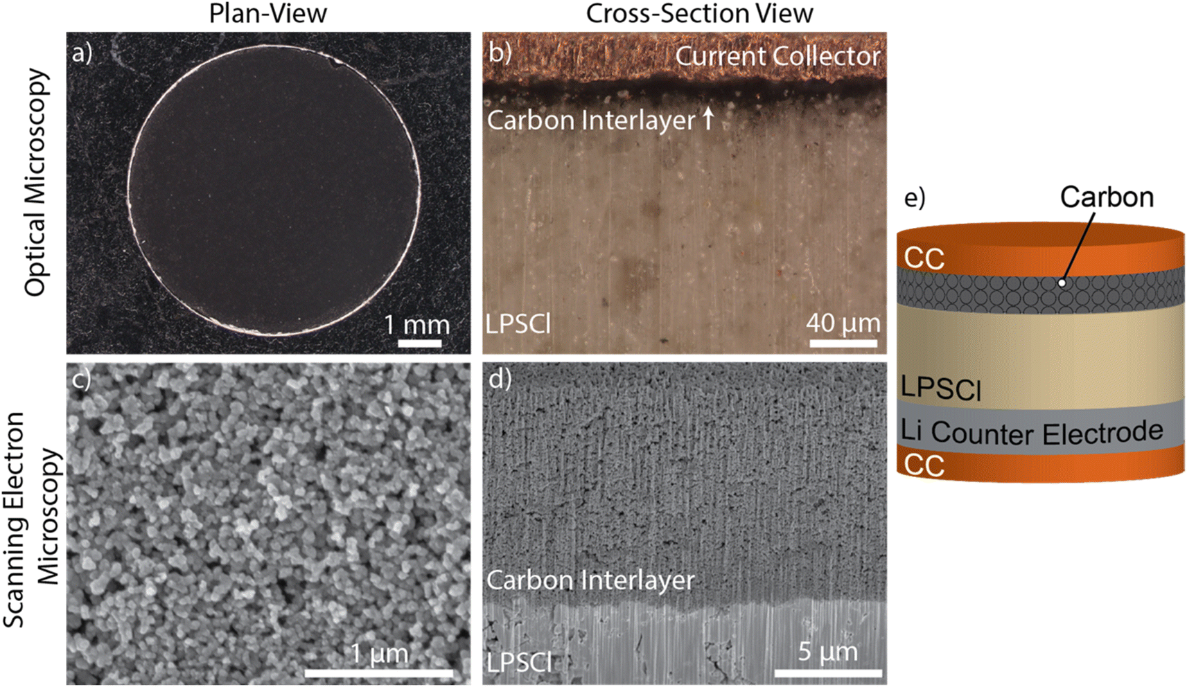 | ||
| Fig. 1 Optical microscopy images of (a) plan-view and (b) cross section of carbon. SEM images of (c) plan-view and (d) PFIB cross section of carbon interlayer on LPSCl solid electrolyte pellet. (e) Resulting Cu/Carbon-LPSCl/Li cell configuration. | ||
After pellet fabrication, Li metal counter electrodes were prepared from bulk Li foil (1.5 mm thick, Thermo Scientific Chemicals). The Li foil surface was scraped to remove the native surface layers until a shiny metallic surface was observed. The Li foil was then compressed under a pressure of 17.7 MPa to form a thin electrode with an approximate thickness of 200 μm. The Li electrode was then interfaced with the SE pellet on the opposite side of the carbon interlayer. Finally, copper (Cu) foils (18 μm thick, Oak Mitsui Inc.) were placed on both sides of the cell stack to serve as CCs (Fig. 1e).
Electrochemical analysis
The assembled cells were inserted into a polyether ether ketone (PEEK) sleeve with a 6 mm diameter through hole. Uniaxial compression was applied using two stainless steel pins in contact with the Cu CCs, and a constant stack pressure of 5 MPa was measured using a mechanical load cell. The cell temperature was maintained at 60 °C using an external heater with closed-loop temperature control. The cell was held at the set temperature and stack pressure under OCV conditions for 1 hour to equilibrate the cell stack before cycling.Electrochemical cycling was performed with an Arbin LBT cycler and EIS was performed using a Gamry Reference 600+ potentiostat. Galvanostatic charging was used to form the Li metal anode in situ at varying current densities (0.01, 0.1, 0.2, 0.5, and 1.0 mA cm−2) for a specified capacity. The current-interrupt measurements consisted of applying a constant current density until reaching cutoff voltages of 0.5, 0.3, 0.1, and 0.01 V, respectively, with each current step followed by a 5 hour OCV period. EIS was performed between 5 MHz and 0.1 Hz.
Materials characterization
Cross-sections were prepared with plasma focused-ion beam (PFIB) milling and imaged using scanning electron microscopy (SEM) performed with a Thermo Fisher Helios G4 PFIB UXe. PFIB cuts were prepared at 15 μA with an accelerating voltage of 30 kV. X-ray photoelectron spectroscopy (XPS) was performed with a Kratos Axis Ultra XPS. A monochromated Al-Kα X-ray source was operated at a 10 mA emission current at 12 kV for all scans. Core scans for each element were collected at a pass energy of 40 eV. The XPS system is directly connected to an Ar glovebox to avoid air exposure to the sample.All optical imaging was performed with a Keyence VHX-7000 4k digital microscope inside an Ar glovebox. Grazing-incident XRD was performed with a Rigaku SmartLab X-ray diffractometer with a 2θ range of 10–80° and incident angle of 0.5–1°. Samples were capped with Kapton tape to prevent air exposure. Raman spectroscopy was performed with a Renishaw spectrometer using 532 nm laser at 50× magnification and 600 l mm−1 grating at a power of ∼0.1 mW. Samples were placed inside a UV quartz cuvette with an air-tight sealed cap to prevent air exposure.
Operando microscopy experiments
To visualize the Li concentration gradients within a carbonaceous interlayer, graphite powder (FormulaBT SLA 1518, 17.7 μm average diameter) was used as a model system for the operando optical microscopy experiments. The graphite powder with an areal loading of 3.5 mg cm−2 was dispersed across one side of the SE pellet and cold pressed at 400 MPa to form the graphite interlayer. As described in our previous report, a planar cross-section was prepared by cutting and polishing one edge of the pellet.50,51 As we have previously shown, the SOC gradients observed along this polished cross-section are consistent with those deeper within the bulk of the pellet.50,51 The cell stack was assembled into a custom visualization fixture, which was maintained at a constant stack pressure of 5 MPa and a temperature of 60 °C for cycling. A Keyence 4k digital microscope and a BioLogic SP-200 potentiostat were used to perform the operando optical microscopy characterization.Results and discussion
Electrochemical analysis on transition in reaction pathway
To study the electrochemical performance of the carbon interlayer, a galvanostatic charging experiment at a current density of 0.1 mA cm−2 was performed to deposit Li metal in an anode-free cell configuration (Cu/Carbon-LPSCl/Li), which was compared to a control sample without a carbon interlayer (Cu/LPSCl/Li), Fig. 2a. A notable difference in the shape of the voltage trace with and without the presence of the carbon interlayer was observed. When the interlayer was present, the voltage profile remains positive for a longer duration than the control sample. The initial sloping profile for the carbon interlayer sample at positive potentials is attributed to the charge capacity that is associated with the lithiation of the carbon interlayer, as well as the formation of SEI as the cell potential drops below the reductive stability limit of LPSCl.52,53 The subsequent minimum observed in the voltage trace below 0 V indicates the onset of Li nucleation. This minimum is followed by a voltage plateau as the plated Li continues to grow.10,54 | ||
| Fig. 2 (a) Galvanostatic charging with and without a carbon interlayer at a current density of 0.1 mA cm−2 for a total charge capacity of 2.0 mA h cm−2. (b) Schematic of the reaction pathways in a cell with a carbon interlayer. Top-down SEM images of a carbon surface are included after charging to a capacity of (c) 0.15 mA h cm−2 and (d) 0.3 mA h cm−2. (e) Cross-sectional PFIB-SEM image of a carbon interlayer after charging to a capacity of 2.0 mA h cm−2. Illustrations of the primary reaction pathways are included below the SEM images. | ||
Building on the theoretical framework for anode-free SSBs in previous reports, the evolution of the voltage trace under galvanostatic charging conditions can be described using an equivalent circuit model shown in Fig. 2b.55–57 Under a constant total applied current, the fractional current associated with the available reaction pathways at the interface will be determined by the relative impedances of each pathway. As charging proceeds, the dynamic changes in these impedances will determine the fractional current distribution associated with each pathway.
In contrast, the control sample exhibits a rapid onset of Li nucleation indicated by a sharp peak followed by a plateau in the voltage trace (Fig. 2a and S3a†). The nucleation peak of the carbon sample was more blunt, as indicated by a larger full width at half maximum compared to the control sample (Fig. S3†). Analogous to previous reports of voltage traces in Li metal anodes, we attribute the reduction in the peak sharpness for the carbon sample to the fact that the transition between reaction pathways is less abrupt when the interlayer is present.36,55,58 We define the amount of areal charge capacity (mA h cm−2) that is passed before reaching 0 V as QLith+SEI, as indicated in Fig. 2a, which was significantly larger in the carbon sample. We further note that the carbon interlayer exhibits a decrease in the voltage minimum associated with Li nucleation from −13.4 ± 1.9 mV to −7.4 ± 0.8 mV, compared to the control sample. This decrease in nucleation potential is consistent throughout the range of tested current densities, as summarized in Table S1.† This reduction in the cell polarization is attributed to a lower overpotential during Li nucleation, which may be attributed to an increase in the kinetic rate constant and/or an increase in interfacial contact area with the SE associated with the presence of the carbon interlayer.30 These trends in interfacial charge-transfer impedance will be discussed later in the paper.
To understand the influence of the carbon interlayer on the onset of Li plating, post-mortem SEM imaging was performed to visualize the morphological changes of the carbon interlayer and plated Li. The first two cells were charged at a constant current density of 0.1 mA cm−2 to a capacity of 0.15 and 0.3 mA h cm−2, respectively, and the Cu CC was subsequently removed to allow for top-down SEM imaging (Fig. 2c and d). This facilitated visualization of the heterogeneous nature of Li nucleation, which results in the precipitation of isolated islands on the top surface of the carbon during the initial stages of Li plating (Fig. 2d). Optical imaging of the carbon surface over a larger field-of-view further reveals the macroscopic variations in the Li morphology after plating a low capacity (Fig. S4†). This heterogenous nucleation behavior is analogous to Li plating on graphite anodes during fast charging in liquid electrolytes, which has been attributed to spatial heterogeneity in the local SOC.35 After passing a capacity of 0.15 mA h cm−2, the cell voltage is still more positive than 0 V, and has no presence of Li deposition on the carbon surface (Fig. 2c). At this early stage of cycling the predominant reaction pathways are carbon lithiation and SEI formation (QLith+SEI). This contrasts with the control sample without a carbon interlayer, where rapid Li nucleation occurs, and plated Li was already observed after a capacity of 0.15 mA h cm−2 (Fig. S5†). After a charge capacity of 0.3 mA h cm−2, which is beyond the nucleation peak, there is clear evidence of agglomerated Li metal that can be observed on top of the carbon surface (Fig. 2d). Additionally, the carbon surface morphology becomes more dense and does not exhibit the porous morphology observed for the pristine carbon surface in Fig. 1c.
After passing a capacity of 2.0 mA h cm−2, a significant amount of Li plating was observed at the interface between the carbon and the CC. Consistent with previous reports, we observe the successful formation of a Li metal anode in situ at the carbon/CC interface, which is possible without the presence of an alloying metal such as silver in the interlayer.20,27,28,31,59 PFIB milling was performed at multiple locations across the pellet surface to enable a cross-sectional visualization of the thick Li deposits (Fig. S6†). After deposition of 2.0 mA h cm−2, dense Li plating is visible across the carbon/CC interface, while the carbon/SE interface maintains conformal contact. At this stage in cycling, the predominant reaction pathway is the growth of plated Li (Fig. 2e).
As shown in Fig. 2, when a carbon interlayer was present at the interface between the SE and CC, lithiation of the carbon interlayer precedes the subsequent nucleation and plating of Li. This is analogous to Li plating in graphite anodes in liquid electrolyte systems, where the transition from lithiation from graphite to Li plating is accelerated under fast charging conditions.35 Therefore, to study how the transition from carbon lithiation to plating is influenced by the charging rate, galvanostatic charging was performed under a range of current densities: 0.01, 0.1, 0.2, 0.5, and 1.0 mA cm−2. The corresponding voltage traces are shown in Fig. 3a, where an increased cell polarization was observed as the current density increases. As a result, the working electrode potential drops below 0 V sooner in the charge cycle, indicating that the transition in the reaction pathway from carbon lithiation to Li plating occurs sooner at higher current densities. In other words, the magnitude of QLith+SEI decreases as the current density increases (Fig. 3b). In contrast, the control sample exhibits a much smaller magnitude of QLith+SEI across all ranges of current densities, indicating that the transition from SEI formation to Li nucleation occurs very rapidly in the absence of a carbon interlayer (Fig. S7†).55
 | ||
| Fig. 3 (a) First charge voltage profile under constant current density at 0.01, 0.1, 0.2, 0.5, and 1.0 mA cm−2. (b) First charge cumulative capacity passed before reaching 0 V for each current density. (c) Schematic of XPS surface scan on carbon interlayer surface. (d) Carbon 1s and lithium 1s XPS core scan before cycling and after lithiation to 10 mV when charged at 0.01, 0.1, and 1.0 mA cm−2. | ||
The thickness of the carbon interlayer was also increased from 13 to 26 μm to investigate the influence of a thicker interlayer on the lithiation behavior (Fig. S8†). The magnitude of QLith+SEI for the thicker interlayer increased as a result of the larger charge capacity of the carbon, and the accessible capacity of the interlayer decreased at high current densities, which is consistent with the observations in Fig. 3. Despite the increase in mass transport distances from using a thicker interlayer, Li deposition is still observed at the carbon/CC interface (Fig. S8c†). These results illustrate the benefits of keeping the carbon interlayer thin as possible to minimize the capacity that is not associated with Li plating.
These observations provide evidence that the carbon interlayer in the SSB system is behaving in an analogous manner to graphite in liquid systems, where the surface concentration of the carbonaceous material reaches a supersaturation condition and precipitates out a secondary Li phase sooner at higher current densities. To provide additional evidence for this theory, we lithiated the carbon interlayer used in this study in a carbonate-based liquid electrolyte at a slow current density (0.01 mA cm−2 and Fig. S9†). The accessible capacity during this lithiation process was 0.26 mA h cm−2, which is similar to that of the carbon interlayer charged at the same current density in the SSB system. Therefore, we conclude that when the current density is sufficiently small, lithiation of the carbon interlayer occurs until the capacity associated with lithiation of carbon is fully utilized (SOCcarbon = 100%), representing an overcharge condition. However, at higher current densities, Li plating initiates before the carbon is fully lithiated (SOCcarbon < 100%).
To investigate the differences in the SOC of carbon as a function of current density, XPS was performed on samples lithiated at 0.01, 0.1, and 1.0 mA cm−2 to a cutoff voltage of 10 mV (Fig. 3c). As shown in Fig. 3c, XPS analysis was performed on the top surface of the carbon interlayer, after removing the Cu CC. This represents the location of the carbon/CC interface in the fully assembled cell. Prior to charging, a pristine carbon interlayer exhibits a single C 1s peak at 285 eV, which is attributed to carbon–carbon bonding,60 and no discernible peaks were observed in the Li 1s core scan (Fig. 3d). Upon lithiation, the carbon interlayer displays an additional carbon peak at a binding energy of 287 eV, indicating the presence of a new carbon bonding environment. This higher energy peak is commonly observed after the lithiation of carbonaceous anodes, and has been observed for the intercalated state of graphite.60,61 Additionally, a peak appears in the Li core scan at a binding energy of ∼58 eV.
When the carbon interlayer was charged at a slow current density of 0.01 mA cm−2, only the higher binding energy peak in the carbon core scan (287 eV) is observed, which indicates that the carbon interlayer is fully lithiated (SOCcarbon = 100%). In contrast, when charged at a faster current density of 0.1 and 1.0 mA cm−2, both carbon peaks are observed (285 and 287 eV), which indicates incomplete lithiation of the carbon interlayer. These observations provide further evidence that when the carbon interlayer is charged at higher current densities, the transition to Li plating occurs when the global SOC of carbon is less than 100%. In LIBs with liquid electrolytes, this transition to Li plating at higher current densities is attributed to a combination of mass transport limitations through the graphite electrode thickness, as well as solid-state diffusion through the graphite particles.35,55,62 These results suggest that local SOC gradients may also drive the earlier onset of nucleation of Li in the carbon interlayer system. Furthermore, these local SOC gradients may continue to dynamically evolve during subsequent cycling processes because a strong gradient in Li concentration is present across the carbon interlayer, which will be explored further in the subsequent sections.
Post-mortem optical and SEM imaging were conducted to demonstrate the earlier onset of Li plating at different charging rates. After charging at a slow current density of 0.01 mA cm−2 to a total capacity of 0.15 mA h cm−2, the cell voltage did not drop below 0 V, which lies within the lithiation and SEI formation regime (QLith+SEI; Fig. 3a). The optical and SEM images presented in Fig. 4a and b show no discernible presence of Li metal. However, when charged at a higher current density of 1.0 mA cm−2 to the same capacity of 0.15 mA h cm−2, heterogenous Li deposits are observed across the carbon surface as shown in Fig. 4c and d. This demonstrates that despite the incomplete lithiation of the carbon interlayer at high current densities, Li metal can still deposit at the carbon/CC interface.
 | ||
| Fig. 4 Optical (a) and (c) and SEM (b) and (d) of top-down carbon samples charged to a capacity of 0.15 mA h cm−2 at 0.01 mA cm−2 (a) and (b) and 1.0 mA cm−2 (c) and (d). | ||
Development of lithium concentration gradients in carbon interlayers
To further understand the dynamic lithiation behavior of the carbon interlayer as a function of current density, EIS and galvanostatic current-interrupt measurements were performed. The carbon interlayers were charged at constant current densities of 0.01 and 1.0 mA cm−2 to different voltage cutoffs (0.5, 0.3, 0.1, and 0.01 V) to investigate the Li+ concentration gradients and their relaxation dynamics. Each current pulse was followed by a 5 hour OCV rest period to allow for the relaxation of any Li concentration gradients (Fig. 5a and d). EIS was performed at the end of each charge step (Fig. 5b and e) and after each OCV rest (Fig. 5c and f). We note that under conditions where significant void formation occurs due to contact loss at the counter electrode Li/SE interface, the EIS spectra can also exhibit dynamic relaxation behavior during OCV rest.63 Therefore, to demonstrate that the relative contributions to the cell impedance from the Li counter electrode and SE interface during these relaxation periods are negligible under the stack pressure (5 MPa) and temperature (60 °C) conditions used in this study, analogous EIS experiments were performed on Li/Li symmetric cells, where no increase in cell impedance was observed during the OCV rest (Fig. S10†). Therefore, the changes observed in the EIS spectra shown in Fig. 5 are attributed to the lithiation and relaxation behavior of the carbon interlayer working electrode.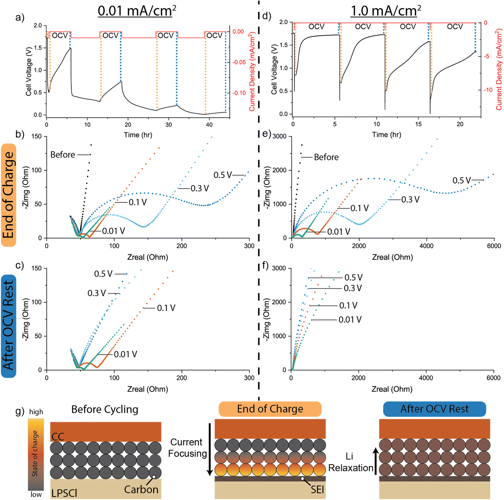 | ||
| Fig. 5 Current-interrupt and EIS measurements of carbon interlayer working electrodes at current densities of 0.01 and 1.0 mA cm−2. (a) Voltage trace during current-interrupt measurements at 0.01 mA cm−2. EIS analysis was performed (b) after the end of each charge step and (c) after the end of each corresponding OCV rest period. (d) Voltage trace during current-interrupt measurements at 1.0 mA cm−2. EIS analysis was performed (e) after the end of each charge step and (f) after the end of each corresponding OCV rest period. Note the larger axis scales compared to panels (b) and (e). (g) Schematic illustration of local SOC gradients through the thickness of the carbon interlayer during lithiation and relaxation. | ||
EIS analysis performed before cycling shows a single feature in the Nyquist plot at high frequencies (Fig. 5b), where the x-intercept does not change significantly throughout the charging and rest process. The high-frequency feature is attributed to the bulk SE impedance, which does not change significantly over the course of the experiment.64,65 At lower frequencies, the Nyquist plot before cycling approaches a vertical line indicating blocking electrode behavior in the unlithiated carbon, which is essentially acting as a current collector with high electronic conductivity and negligible Li activity (Fig. 5b).10,66 When charged at the lower current density of 0.01 mA cm−2, the cell voltage quickly reaches the 0.5 V cutoff as the current is applied. EIS analysis that was performed at the end of the charge step indicates that the blocking electrode behavior transforms into a non-blocking electrode with the formation of a charge-transfer semi-circle at the intermediate frequency range and a Warburg diffusion tail at low frequencies (Fig. 5b).10,67,68 The transition from blocking to non-blocking behavior is attributed to the lithiation of the carbon interlayer, where the activity of Li at the carbon/SE interface becomes non-zero. The Nyquist spectra were fitted using an equivalent-circuit model as summarized in Table S2.† During the 5 hour OCV rest, the voltage of the cell quickly rises to 1.5 V (Fig. 5a, further details in Table S3†). EIS analysis performed at the end of the corresponding OCV rest shows only a Warburg tail at low frequencies (Fig. 5c). To provide a more detailed measurement of the impedance evolution throughout the relaxation period, EIS was performed in one-hour increments throughout an OCV rest period, which shows a continuous increase in charge-transfer impedance (Fig. S11†). The disappearance of the interfacial charge-transfer semi-circle during the OCV rest period is attributed to the relaxation of Li concentration gradients in the carbon interlayer, which results in a corresponding decrease in Li activity at the carbon/SE interface.
This relaxation behavior is illustrated in Fig. 5g, where the initial SOC gradient formed during charging results in a high local concentration (activity) of Li in the carbon phase at the carbon/SE interface. During OCV rest, the gradients in local SOC throughout the carbon interlayer thickness provide a driving force for equilibration. Specifically, the higher concentration of Li at the carbon/SE interface will drive the diffusion of Li deeper within the interlayer (away from the carbon/SE interface). This behavior is analogous to the formation and relaxation of local SOC gradients throughout the thickness of porous graphite anodes during the fast charging of Li-ion batteries in liquid electrolytes.33,38 As previously shown through operando optical analysis, during OCV rest periods, SOC gradients that form in porous graphite anodes relax during re-equilibration, which is primarily driven by galvanic corrosion reactions that are facilitated by the presence of the liquid electrolyte phase within the porous electrode.35,69,70 While solid-state diffusion of Li can also drive re-equilibration, the relative rate of corrosion reactions was shown to be significantly higher when a liquid electrolyte is present. However, in the case of carbon interlayers in SSB systems, there is no electrolyte phase present within the pores of the interlayer. Therefore, the re-equilibration in SOC must be driven by solid-state diffusion. According to Fick's laws, the rate of diffusion will be dependent on the local concentration gradients, which will further be influenced by the applied current density during charging.
Upon continued lithiation to 0.3 V after the first OCV rest period, the charge-transfer semi-circle re-forms and reaches a lower impedance value compared to the end of the 0.5 V charge step (Fig. 5b). After the 5 hour OCV rest, the charge-transfer resistance increases in magnitude from 27 to 361 Ohms cm2 (Table S2†). This indicates that the carbon interlayer is sufficiently lithiated to maintain a charge transfer semi-circle but still undergoes re-equilibration, as evidenced by the increase in impedance under OCV conditions. The subsequent lithiation step to 0.1 V follows a similar impedance increase after OCV rest, indicating that a Li concentration gradient is still present. Once lithiated to 0.01 V, the charge transfer resistance is reduced to 2.5 Ohm cm2.30 We note that this low value of charge transfer resistance is comparable to that of high-quality Li/SE interfaces, despite the fact that Li has not yet been plated in the system.18 This highlights one important benefit of the carbon interlayer with SSBs: it enables a conformal, low-resistance interface with the SE material, which has been proposed to play an important role in the uniformity of the current distribution across the interface during plating.30 Furthermore, minimal changes were observed in the impedance spectra and OCV profile after the 5 hour rest period, indicating that the global SOC of the carbon interlayer is nearly 100%, with minimal Li concentration gradients present.
These dynamic changes in the EIS spectra and OCV rise are exclusive to the carbon interlayer and are not observed in a control sample where no carbon interlayer is present. For the case of an anode-free CC/SE interface, the voltage quickly rises to the initial OCV of 1.71 V after charging to each positive voltage cutoff (Fig. S12a–c†).
The rate and magnitude of the changes in the OCV profile of the carbon interlayer can be seen more clearly at a higher current density of 1.0 mA cm−2 (Fig. 5d). After lithiation to each voltage cutoff, the high-frequency SE impedance feature is discernible; however, the magnitude of the charge-transfer resistance for each cutoff voltage is more than one order-of-magnitude larger than the equivalent resistance when the cell was charged at 0.01 mA cm−2 (Fig. 5e). These differences will be affected by both the larger IR drop and larger electrode overpotentials at higher current densities, which will affect the initial SOC distribution within the carbon interlayer before relaxation. We further note that the total charge capacity passed during each current pulse is lower at higher current density because of the higher cell polarization. After each OCV rest, the charge-transfer semi-circle evolves towards blocking electrode behavior (Fig. 5f). Unlike the 0.01 mA cm−2 condition, even when the cell was lithiated to 0.01 V cutoff there is no discernible charge-transfer semi-circle after relaxation. This is further evidence of the relaxation of the Li concentration gradients in the carbon interlayer, which will result in a lower Li activity at the carbon/SE interface because of the lower amount of charge capacity passed. These experiments were also performed at an intermediate current density of 0.1 mA cm−2, which followed similar trends as the low and high rates (Fig. S12d–f†).
In addition to current density, the effects of temperature on the relaxation behavior were also explored. A more rapid voltage increase during the OCV rest is observed at elevated temperatures, which is attributed to an increased rate of relaxation of the concentration gradients from solid-state diffusion (Fig. S13†). Overall, these results illustrate the complex dynamics occurring within the carbon interlayer during charging, which will be influenced by the specific charge protocols used during cycling.
Operando video microscopy of Li concentration gradient
To provide a visualization of the development and relaxation of Li concentration gradients throughout the interface region between the SE and carbon interlayer, operando cross-sectional video microscopy was performed using graphite as a model system. Graphite was used as a proxy for the carbon interlayer because it is known to change color as a function of SOC.35,37 A constant current density of 0.1 mA cm−2 was used to lithiate the graphite interlayer to a cutoff voltage of 0.01 V, which is followed by a 20 hours OCV rest (Fig. 6 and Supplementary Video†). | ||
| Fig. 6 (a) Operando optical microscopy images of Gr/LPSCl/Li cell lithiated at a constant current density of 0.1 mA cm−2 to a cutoff voltage of 10 mV, followed by a prolonged OCV rest. Optical images of the graphite interlayer cross-section are shown (b) before cycling, (c) after lithiation, (d) after 5 hours OCV rest, and (e) after 20 hours OCV rest. | ||
Before cycling, the graphite has a gray color (Fig. 6b). After lithiation to 0.01 V, the graphite particles nearest to the bulk SE interface transition to gold, which is indicative of the highly lithiated (LiC6) phase. Moving away from the SE interface toward the CC, a gradient in the graphite color is observed (Fig. 6c) from gold (LiC6) to red (LiC12) to blue (LiC18). This color gradient illustrates the spatially varying SOC throughout the graphite thickness, where approximately 50% of the graphite particles transition to gold color.35 This is consistent with previous operando video microscopy observations of graphite anodes in SSBs, where Li transport is limited through the electrode thickness.50,51 After the lithiation step, the Li concentration gradient is allowed to relax during OCV, where after 5 hours, the gold particles closest to the SE interface start to transition to the red phase, while the phase boundary between red and blue has propagated towards the CC (Fig. 6d). After 20 hours, the blue phase is no longer visible, and the electrode is fully composed of gold and red particles (Fig. 6e).
These operando visualization experiments were repeated in a separate cell that was lithiated at 1.0 mA cm−2 (Fig. S14†). At a higher current density, the formation of strong concentration gradients localized to the graphite/SE interface is observed, where only ∼2% of the graphite particles transition to gold color. In summary, operando video microscopy provides visual evidence to support the electrochemical analysis provided in the previous sections, where an SOC gradient within the carbon interlayer initially forms during charging, and subsequently relaxes away from the SE interface during the OCV rest period.
Influence of Li concentration gradient on Li plating
In the previous sections, we have demonstrated evidence for the formation and relaxation of Li concentration gradients in the carbon interlayer during charging. Next, the influence of these Li concentration gradients on the subsequent Li plating behavior will be examined. Similar to the experiments described above, two different current densities (0.01 and 1.0 mA cm−2) were used for galvanostatic charging of the carbon interlayer; however, in these experiments the cell voltage was allowed to drop below 0 V, resulting in Li plating. As shown in Fig. 7a and c, the charge capacity passed before reaching 0 V (QLith+SEI) decreases at the higher current density, which is consistent with Fig. 3a and b. As we have shown in the previous sections, this reduced global SOC of the carbon interlayer is associated with the presence of Li concentration gradients. After reaching 0 V, a fixed amount of charge capacity was passed, which is used to define the quantity of plated Li (Qplate, Fig. 7a and c). After passing a specified quantity of plated Li (0.05, 0.15, or 0.3 mA h cm−2), the cell was held under open-circuit conditions for 24 hours to track the evolution of the voltage trace (Fig. 7b and d). | ||
| Fig. 7 (a) Charging voltage trace at current density of 0.01 mA cm−2 for plated lithium capacity (Qplate) of 0.15 mA h cm−2. (b) Resulting OCV traces for Qplate of 0.05 and 0.15 mA h cm−2. (c) Charging voltage trace at current density of 1.0 mA cm−2 for a Qplate of 0.3 mA h cm−2. (d) Resulting OCV traces for Qplate of 0.05, 0.15, and 0.3 mA h cm−2. | ||
When charging at the slow current density of 0.01 mA cm−2 and plating a Li capacity (Qplate) of 0.05 mA h cm−2 (Fig. 7a), the OCV immediately after plating was 0 V (Fig. 7b), indicating successful deposition of Li metal. The OCV remains ∼0 V for a duration of 6 hours, which is in contrast with the OCV behavior when the carbon interlayer was lithiated to a cutoff voltage of 0.01 V (Fig. 5a), where a slow OCV rise was observed immediately after lithiation. We attribute this difference in the OCV behavior to the fact that the lithiated carbon interlayer is acting as a MEIC,32 and therefore, the electrode potential is defined by the Li metal/carbon interlayer interface. However, after 6 hours, the OCV gradually increases up to 0.25 V. This change in OCV indicates that the electrochemically active interface that defines the electrode potential is no longer associated with the Li metal/MEIC interface. We hypothesize that the reason for this change is the solid-state lithiation of the carbon interlayer, which will consume the active Li material inventory because only a small volume of plated Li is present, and the carbon interlayer was not fully lithiated even at 0.01 mA cm−2, as indicated by the relaxation of concentration gradients at this current density in Fig. 5a. In the present study, we do not believe that SEI formation plays a significant role in the observed OCV behavior because when the same quantity of Li was plated in a control experiment where no carbon interlayer was present, the OCV remained constant at 0 V over the entire 24 hour period (Fig. S15†).
To provide further evidence for this proposed mechanism, the Qplate was increased to 0.15 mA h cm−2 while maintaining the same current density of 0.01 mA cm−2. When Qplate was increased, the OCV remained constant at 0 V throughout the entire 24 hour period (Fig. 7b). We attribute this to the fact that Qplate was larger than the remaining unlithiated capacity of the carbon interlayer, so that even after solid-state lithiation occurs, an active Li metal/MEIC interface remains.
When a higher current density of 1.0 mA cm−2 was applied with a Qplate of 0.05 mA h cm−2, the subsequent OCV trace immediately increased to positive voltage, reaching 1.8 V after the 24 hours period. This rise indicates a rapid loss of active Li inventory across the carbon interlayer after Li metal deposition. This is in contrast to the OCV behavior when the same quantity of Qplate was passed at a slow current density, where the initial OCV remained 0 V for 6 hours before a more slow rise in OCV. One possible reason for this difference is the fact that under fast charging conditions, there will be a larger gradient in the concentration of Li within the lithiated carbon interlayer phase. As a consequence, the concentration gradients within the carbon interlayer will re-equilibrate via solid-state diffusion at a faster rate, as evidenced by the faster rise in OCV after lithiating to a cutoff voltage of 0.01 V in Fig. 5. In the presence of plated Li, the surface concentration of Li atoms within the carbon phase will affect the kinetics of the solid-state lithiation reaction. Therefore, under high current density conditions, because the surface concentration of Li within the carbon phase will deplete at a faster rate from solid-state diffusion, the rate of lithiation from the adjacent Li metal will be faster. This helps to rationalize why the OCV remains 0 V for 6 hours when Qplate was 0.05 mA h cm−2 at a slow current density, but the OCV immediately rises when the same Qplate was applied at a higher current density. In addition to these concentration-dependent effects, there may be other factors that also influence the rate of solid-state lithiation of the carbon interlayer, including differences in nucleation and growth behavior of plated Li. Regardless, these results demonstrate that the presence of concentration gradients in the carbon interlayer will have an influence on the subsequent Li plated behavior in anode-free SSBs.
To further demonstrate the feasibility of solid-state lithiation of the carbon interlayer when in contact with metallic Li, XPS analysis was conducted (Fig. S16†). For these experiments, a pristine (unlithiated) carbon interlayer was placed in contact with a bulk Li metal foil and immediately inserted into the XPS chamber. The opposite (exposed) surface of the carbon interlayer was analyzed by XPS to study the temporal evolution of lithium content within the carbon. Analogous to Fig. 3, the C 1s core progressively shifts from a singular peak at 285 eV to a double peak, accompanied by the emergence of a Li 1s peak at 56.5 eV. This evolution signifies the gradual lithiation of the carbon interlayer through solid-state reaction chemistry.
Following the experimental protocol of the slow current condition, the plated Li capacity (Qplate) was also increased to 0.15 mA h cm−2 at a higher current density of 1.0 mA cm−2. In this case, the OCV remains near 0 V for approximately 5 hours, before rising up to 0.18 V at the end of the 24 hour rest period. This is qualitatively similar to what was observed for the smaller Qplate value (0.05 mA h cm−2) under slow charge conditions. However, unlike the same Qplate value (0.15 mA h cm−2) at 0.01 mA cm−2, where the OCV remained constant at 0 V throughout the 24 hours period, the OCV eventually rises when the carbon was lithiated at the faster rate. Only after a higher Qplate of 0.3 mA h cm−2 has passed at the high current density does the OCV remain at 0 V throughout the 24 hours period.
In summary, when the carbon interlayer was charged at a higher current density, a larger capacity of plated Li was necessary to establish a stable Li metal anode. The differences in the Li nucleation and subsequent re-equilibration with the carbon interlayer were strongly affected by the presence of concentration gradients within the carbon interlayer. Furthermore, the presence of a carbon interlayer was shown to introduce new reaction pathways and associated electrochemical dynamics, which are not present in anode-free SSBs without MEIC interlayers. These observations indicate that the lithiation of the carbon interlayer prior to Li nucleation is crucial for the successful in situ formation of a Li metal anode.
Conclusion
This work presents a fundamental study of the lithiation of carbonaceous interlayers in anode-free SSBs, which can form Li concentration gradients when charged at varying current densities. These dynamic changes in the local SOC distribution of the carbon interlayer can have subsequent influence on the interfacial impedance, relaxation dynamics, and nucleation behavior of in situ formed Li metal anodes. Specifically, the key findings of this study are that:(1) The incorporation of a carbon interlayer at the anode-free interface results in an additional reaction pathway (carbon lithiation) prior to Li metal nucleation. The transition in the reaction pathway between carbon lithiation and Li nucleation occurs earlier when charging at higher current densities. Therefore, the nucleation and growth of Li metal can occur before the carbon interlayer is fully lithiated.
(2) Gradients in the Li concentration (local SOC) distribution throughout the thickness carbon interlayer were studied using a combination of EIS, current-interrupt measurements, XPS, and operando video microscopy. When charging at high current densities these Li concentration gradients increase in magnitude. The Li concentration gradients can subsequently relax during OCV rest periods after charging, causing an increase in the charge-transfer impedance as a result of the corresponding decrease of Li activity at carbon/SE interface. The relaxation of these gradients occurs through a solid-state diffusion mechanism, which was visualized using operando video microscopy.
(3) Owing to the incomplete lithiation of the carbon interlayer at high current densities, after the onset of Li metal nucleation, some of the plated Li content is transferred into the interlayer through solid-state lithiation. The presence of Li concentration gradients in carbon at different current densities is shown to influence both the nucleation and subsequent re-lithiation dynamics. These observations highlight the importance of understanding the dynamic changes that occur during the initial formation cycling of a carbon interlayer to control the nucleation, growth, and stability of anode-free SSBs.
In the future, the results from this study can inform the optimal design and charging protocols for a variety of MEIC interlayer compositions and structures for anode-free SSBs. Variables that will influence the lithiation, relaxation, and plating behavior include interlayer thickness, temperature, particle size, porosity/composition, and the inclusion of lithiophilic additives such as Ag.20 The mechanistic insights developed in this study can be used to inform model-based design and interpretation of these interlayers, towards the goal of enabling high-performance anode-free SSBs.
Conflicts of interest
There are no conflicts to declare.Acknowledgements
This work was supported by Nissan Motor Co., Ltd, Japan. D. W. L. acknowledges support from the National Science Foundation Graduate Research Fellowship Program under Grant No. DGE-1256260.References
- J. G. Kim, B. Son, S. Mukherjee, N. Schuppert, A. Bates, O. Kwon, M. J. Choi, H. Y. Chung and S. Park, J. Power Sources, 2015, 282, 299–322 CrossRef CAS.
- B. Scrosati and J. Garche, J. Power Sources, 2010, 195, 2419–2430 CrossRef CAS.
- C. Li, Z. Yu Wang, Z. Jiang He, Y. Jiao Li, J. Mao, K. Hua Dai, C. Yan and J. Chao Zheng, Sustainable Mater. Technol., 2021, 29, e00297 CrossRef CAS.
- T. Krauskopf, F. H. Richter, W. G. Zeier and J. Janek, Chem. Rev., 2020, 120, 7745–7794 CrossRef CAS PubMed.
- P. Albertus, S. Babinec, S. Litzelman and A. Newman, Nat. Energy, 2017, 3, 16–21 CrossRef.
- M. J. Wang, E. Kazyak, N. P. Dasgupta and J. Sakamoto, Joule, 2021, 5, 1371–1390 CrossRef CAS.
- B. J. Neudecker, N. J. Dudney and J. B. Bates, J. Electrochem. Soc., 2000, 147, 517 CrossRef CAS.
- J. A. Lewis, S. E. Sandoval, Y. Liu, D. L. Nelson, S. G. Yoon, R. Wang, Y. Zhao, M. Tian, P. Shevchenko, E. Martínez-Pañeda and M. T. McDowell, Adv. Energy Mater., 2023, 13, 2204186 CrossRef CAS.
- T. Fuchs, J. Becker, C. G. Haslam, C. Lerch, J. Sakamoto, F. H. Richter and J. Janek, Adv. Energy Mater., 2023, 13, 2203174 CrossRef CAS.
- M. J. Wang, E. Carmona, A. Gupta, P. Albertus and J. Sakamoto, Nat. Commun., 2020, 11, 1–9 CrossRef PubMed.
- A. Banerjee, X. Wang, C. Fang, E. A. Wu and Y. S. Meng, Chem. Rev., 2020, 120, 6878–6933 CrossRef CAS PubMed.
- D. K. Singh, T. Fuchs, C. Krempaszky, P. Schweitzer, C. Lerch, F. H. Richter and J. Janek, Matter, 2023, 6, 1463–1483 CrossRef CAS.
- B. S. Vishnugopi, K. G. Naik, H. Kawakami, N. Ikeda, Y. Mizuno, R. Iwamura, T. Kotaka, K. Aotani, Y. Tabuchi, P. P. Mukherjee, B. S. Vishnugopi, K. G. Naik, P. P. Mukherjee, H. Kawakami, N. Ikeda, Y. Mizuno, R. Iwamura, T. Kotaka, K. Aotani and Y. Tabuchi, Adv. Energy Mater., 2023, 13, 2203671 CrossRef CAS.
- K. B. Hatzell, X. C. Chen, C. L. Cobb, N. P. Dasgupta, M. B. Dixit, L. E. Marbella, M. T. McDowell, P. P. Mukherjee, A. Verma, V. Viswanathan, A. S. Westover and W. G. Zeier, ACS Energy Lett., 2020, 5, 922–934 CrossRef CAS.
- M. B. Dixit, A. Verma, W. Zaman, X. Zhong, P. Kenesei, J. S. Park, J. Almer, P. P. Mukherjee and K. B. Hatzell, ACS Appl. Energy Mater., 2020, 3, 9534–9542 CrossRef CAS.
- J. A. Lewis, J. Tippens, F. J. Q. Cortes and M. T. McDowell, Trends Chem., 2019, 1, 845–857 CrossRef CAS.
- J. A. Lewis, F. J. Q. Cortes, Y. Liu, J. C. Miers, A. Verma, B. S. Vishnugopi, J. Tippens, D. Prakash, T. S. Marchese, S. Y. Han, C. Lee, P. P. Shetty, H. W. Lee, P. Shevchenko, F. De Carlo, C. Saldana, P. P. Mukherjee and M. T. McDowell, Nat. Mater., 2021, 20, 503–510 CrossRef CAS PubMed.
- A. Sharafi, E. Kazyak, A. L. Davis, S. Yu, T. Thompson, D. J. Siegel, N. P. Dasgupta and J. Sakamoto, Chem. Mater., 2017, 29, 7961–7968 CrossRef CAS.
- C. Wang, Y. Zhao, Q. Sun, X. Li, Y. Liu, J. Liang, X. Li, X. Lin, R. Li, K. R. Adair, L. Zhang, R. Yang, S. Lu and X. Sun, Nano Energy, 2018, 53, 168–174 CrossRef CAS.
- Y. G. Lee, S. Fujiki, C. Jung, N. Suzuki, N. Yashiro, R. Omoda, D. S. Ko, T. Shiratsuchi, T. Sugimoto, S. Ryu, J. H. Ku, T. Watanabe, Y. Park, Y. Aihara, D. Im and I. T. Han, Nat. Energy, 2020, 5, 299–308 CrossRef CAS.
- G. Zheng, S. W. Lee, Z. Liang, H. W. Lee, K. Yan, H. Yao, H. Wang, W. Li, S. Chu and Y. Cui, Nat. Nanotechnol., 2014, 9, 618–623 CrossRef CAS PubMed.
- K.-H. Chen, A. J. Sanchez, E. Kazyak, A. L. Davis, N. P. Dasgupta, K. Chen, A. J. Sanchez, E. Kazyak, A. L. Davis and N. P. Dasgupta, Adv. Energy Mater., 2019, 9, 1802534 CrossRef.
- K. Yan, Z. Lu, H. W. Lee, F. Xiong, P. C. Hsu, Y. Li, J. Zhao, S. Chu and Y. Cui, Nat. Energy, 2016, 1, 1–8 Search PubMed.
- Y. Wang, Y. Liu, M. Nguyen, J. Cho, N. Katyal, B. S. Vishnugopi, H. Hao, R. Fang, N. Wu, P. Liu, P. P. Mukherjee, J. Nanda, G. Henkelman, J. Watt and D. Mitlin, Adv. Mater., 2023, 35, 2206762 CrossRef CAS PubMed.
- C. Haslam and J. Sakamoto, J. Electrochem. Soc., 2023, 170, 040524 CrossRef CAS.
- S. E. Sandoval, F. J. Q. Cortes, E. J. Klein, J. A. Lewis, P. P. Shetty, D. Yeh and M. T. McDowell, J. Electrochem. Soc., 2021, 168, 100517 CrossRef CAS.
- N. Suzuki, N. Yashiro, S. Fujiki, R. Omoda, T. Shiratsuchi, T. Watanabe and Y. Aihara, Adv. Energy Sustainability Res., 2021, 2, 2100066 CrossRef CAS.
- D. Spencer-Jolly, V. Agarwal, C. Doerrer, B. Hu, S. Zhang, D. L. R. Melvin, H. Gao, X. Gao, P. Adamson, O. V. Magdysyuk, P. S. Grant, R. A. House and P. G. Bruce, Joule, 2023, 7, 503–514 CrossRef CAS.
- S. Risal, C. Wu, F. Wang, S. Risal, F. C. Robles Hernandez, W. Zhu, Y. Yao and Z. Fan, Carbon, 2023, 213, 118225 CrossRef CAS.
- C. Wu, B. Emley, L. Zhao, Y. Liang, Q. Ai, Z. Chen, F. C. Robles Hernández, F. Wang, S. Risal, H. Guo, J. Lou, Y. Yao and Z. Fan, Nano Lett., 2023, 23, 4415–4422 CrossRef CAS PubMed.
- J.-S. Kim, G. Yoon, S. Kim, S. Sugata, N. Yashiro, S. Suzuki, M.-J. Lee, R. Kim, M. Badding, Z. Song, J. Chang and D. Im, Nat. Commun., 2023, 14, 1–11 Search PubMed.
- Y. Chen, Z. Wang, X. Li, X. Yao, C. Wang, Y. Li, W. Xue, D. Yu, S. Y. Kim, F. Yang, A. Kushima, G. Zhang, H. Huang, N. Wu, Y. W. Mai, J. B. Goodenough and J. Li, Nature, 2020, 578, 251–255 CrossRef CAS PubMed.
- P. P. Paul, E. J. McShane, A. M. Colclasure, N. Balsara, D. E. Brown, C. Cao, B. R. Chen, P. R. Chinnam, Y. Cui, E. J. Dufek, D. P. Finegan, S. Gillard, W. Huang, Z. M. Konz, R. Kostecki, F. Liu, S. Lubner, R. Prasher, M. B. Preefer, J. Qian, M. T. F. Rodrigues, M. Schnabel, S. B. Son, V. Srinivasan, H. G. Steinrück, T. R. Tanim, M. F. Toney, W. Tong, F. Usseglio-Viretta, J. Wan, M. Yusuf, B. D. McCloskey and J. Nelson Weker, Adv. Energy Mater., 2021, 11, 2100372 CrossRef CAS.
- T. Waldmann, B. I. Hogg and M. Wohlfahrt-Mehrens, J. Power Sources, 2018, 384, 107–124 CrossRef CAS.
- Y. Chen, K. H. Chen, A. J. Sanchez, E. Kazyak, V. Goel, Y. Gorlin, J. Christensen, K. Thornton and N. P. Dasgupta, J. Mater. Chem. A, 2021, 9, 23522–23536 RSC.
- K. N. Wood, E. Kazyak, A. F. Chadwick, K. H. Chen, J. G. Zhang, K. Thornton and N. P. Dasgupta, ACS Cent. Sci., 2016, 2, 790–801 CrossRef CAS PubMed.
- T. Gao, Y. Han, D. Fraggedakis, S. Das, T. Zhou, C. N. Yeh, S. Xu, W. C. Chueh, J. Li and M. Z. Bazant, Joule, 2021, 5, 393–414 CrossRef CAS.
- Y. Chen, L. Torres-Castro, K. H. Chen, D. Penley, J. Lamb, M. Karulkar and N. P. Dasgupta, J. Power Sources, 2022, 539, 231601 CrossRef CAS.
- A. Adam, E. Knobbe, J. Wandt and A. Kwade, J. Power Sources, 2021, 495, 229794 CrossRef CAS.
- T. Waldmann, B. I. Hogg and M. Wohlfahrt-Mehrens, J. Power Sources, 2018, 384, 107–124 CrossRef CAS.
- J. H. Park, H. Yoon, Y. Cho and C. Y. Yoo, Materials, 2021, 14, 4683 CrossRef CAS PubMed.
- H. Gong, Y. Chen, S. Chen, C. Xu, Y. Yang, Y. Ye, Z. Huang, R. Ning, Y. Cui and Z. Bao, ACS Energy Lett., 2022, 7, 4417–4426 CrossRef CAS.
- Y. Sun, G. Zheng, Z. W. Seh, N. Liu, S. Wang, J. Sun, H. R. Lee and Y. Cui, Chem, 2016, 1, 287–297 CAS.
- Y. Son, T. Lee, B. Wen, J. Ma, C. Jo, Y. G. Cho, A. Boies, J. Cho and M. De Volder, Energy Environ. Sci., 2020, 13, 3723–3731 RSC.
- C. Martin, M. Genovese, A. J. Louli, R. Weber and J. R. Dahn, Joule, 2020, 4, 1296–1310 CrossRef CAS.
- X. Lu, M. Lagnoni, A. Bertei, S. Das, R. E. Owen, Q. Li, K. O'Regan, A. Wade, D. P. Finegan, E. Kendrick, M. Z. Bazant, D. J. L. Brett and P. R. Shearing, Nat. Commun., 2023, 14, 1–14 CAS.
- E. M. Lotfabad, P. Kalisvaart, A. Kohandehghan, D. Karpuzov and D. Mitlin, J. Mater. Chem. A, 2014, 2, 19685–19695 RSC.
- A. C. Ferrari, Solid State Commun., 2007, 143, 47–57 CrossRef CAS.
- H. Yadegari, M. A. Koronfel, K. Wang, D. B. Thornton, I. E. L. Stephens, C. Molteni, P. D. Haynes and M. P. Ryan, ACS Energy Lett., 2021, 6, 1633–1638 CrossRef CAS.
- A. L. Davis, V. Goel, D. W. Liao, M. N. Main, E. Kazyak, J. Lee, K. Thornton and N. P. Dasgupta, ACS Energy Lett., 2021, 6, 2993–3003 CrossRef CAS.
- M. K. Jangid, A. L. Davis, D. W. Liao and N. P. Dasgupta, ACS Energy Lett., 2023, 20, 2522–2531 CrossRef.
- D. H. S. Tan, E. A. Wu, H. Nguyen, Z. Chen, M. A. T. Marple, J. M. Doux, X. Wang, H. Yang, A. Banerjee and Y. S. Meng, ACS Energy Lett., 2019, 12, 2418–2427 CrossRef.
- S. K. Otto, L. M. Riegger, T. Fuchs, S. Kayser, P. Schweitzer, S. Burkhardt, A. Henss and J. Janek, Adv. Mater. Interfaces, 2022, 9, 2102387 CrossRef CAS.
- A. Pei, G. Zheng, F. Shi, Y. Li and Y. Cui, Nano Lett., 2017, 17, 1132–1139 CrossRef CAS PubMed.
- A. L. Davis, E. Kazyak, D. W. Liao, K. N. Wood and N. P. Dasgupta, J. Electrochem. Soc., 2021, 168, 070557 CrossRef CAS.
- P. Biswal, S. Stalin, A. Kludze, S. Choudhury and L. A. Archer, Nano Lett., 2019, 19, 8191–8200 CrossRef CAS PubMed.
- D. O. Raleigh, J. Phys. Chem., 1967, 71, 1785–1797 CrossRef CAS.
- K. H. Chen, K. N. Wood, E. Kazyak, W. S. Lepage, A. L. Davis, A. J. Sanchez and N. P. Dasgupta, J. Mater. Chem. A, 2017, 5, 11671–11681 RSC.
- M. H. Futscher, T. Amelal, J. Sastre, A. Müller, J. Patidar, A. Aribia, K. Thorwarth, S. Siol and Y. E. Romanyuk, J. Mater. Chem. A, 2022, 10, 15535–15542 RSC.
- A. M. Andersson, A. Henningson, H. Siegbahn, U. Jansson and K. Edström, J. Power Sources, 2003, 119–121, 522–527 CrossRef CAS.
- K. N. Wood and G. Teeter, ACS Appl. Energy Mater., 2018, 1, 4493–4504 CrossRef CAS.
- Y. Chen, L. Torres-Castro, K. H. Chen, D. Penley, J. Lamb, M. Karulkar and N. P. Dasgupta, J. Power Sources, 2022, 539, 231601 CrossRef CAS.
- K. Lee, E. Kazyak, M. J. Wang, N. P. Dasgupta and J. Sakamoto, Joule, 2022, 6, 2547–2565 CrossRef CAS.
- P. Vadhva, J. Hu, M. J. Johnson, R. Stocker, M. Braglia, D. J. L. Brett and A. J. E. Rettie, ChemElectroChem, 2021, 8, 1930–1947 CrossRef CAS.
- L. M. Riegger, S. Mittelsdorf, T. Fuchs, R. Rueß, F. H. Richter and J. Janek, Chem. Mater., 2023, 35, 5091–5099 CrossRef CAS.
- N. Ogihara, S. Kawauchi, C. Okuda, Y. Itou, Y. Takeuchi and Y. Ukyo, J. Electrochem. Soc., 2012, 159, A1034–A1039 CrossRef CAS.
- A. S. Keefe, S. Buteau, I. G. Hill and J. R. Dahn, J. Electrochem. Soc., 2019, 166, A3272–A3279 CrossRef CAS.
- G. Gourdin, P. H. Smith, T. Jiang, T. N. Tran and D. Qu, J. Electroanal. Chem., 2013, 688, 103–112 CrossRef CAS.
- C. von Lüders, V. Zinth, S. V. Erhard, P. J. Osswald, M. Hofmann, R. Gilles and A. Jossen, J. Power Sources, 2017, 342, 17–23 CrossRef.
- X. G. Yang, S. Ge, T. Liu, Y. Leng and C. Y. Wang, J. Power Sources, 2018, 395, 251–261 CrossRef CAS.
Footnote |
| † Electronic supplementary information (ESI) available. See DOI: https://doi.org/10.1039/d3ta05890e |
| This journal is © The Royal Society of Chemistry 2024 |