
Inhibition of oxygen release and stabilization of the bulk structure of lithium-rich layered oxides by strong Mo–O covalent binding†
Huinan
Yu
a,
Zhichen
Xue
a,
Zhiyuan
Xue
a,
Zhongyuan
Luo
a,
Chenxi
Ding
a,
Guorong
Hu
abc,
Zhongdong
Peng
abc,
Yanbing
Cao
 abc and
Ke
Du
*abc
abc and
Ke
Du
*abc
aSchool of Metallurgy and Environment, Central South University, Changsha, 410083, China. E-mail: dukecsu@163.com
bEngineering Research Center of the Ministry of Education for Advanced Battery Materials, Central South University, Changsha, 410083, China
cHunan Provincial Key Laboratory of Nonferrous Value-added Metallurgy, Central South University, Changsha, 410083, China
First published on 1st December 2023
Abstract
Lithium-rich layered oxides (LLOs) are highly promising materials for next-generation lithium-ion batteries. However, the irreversible oxygen release during charging and discharging can cause severe interfacial side reactions and unfavorable phase transitions, leading to capacity and voltage drops continuously, which is the root cause of deterioration in the performance of LLOs. In this study, an effective modification strategy of constructing strong covalent Mo–O bonds is proposed to change the local coordination environment of oxygen in LLOs and thus inhibits the release of lattice oxygen during cycling. It improves the migration barrier of transition metal elements, suppresses Mn reduction during the cycling process, prevents the occurrence of phase transition from layered to spinel, and plays a role in stabilizing the crystal structure. Moreover, lattice oxygen fixation prevents the release of O−/O2n− (0 < n < 4) species into the electrolyte that leads to undesirable interfacial reactions, and reduces the generation of a series of unfavorable film-forming organics, such as ROCO2Li and ROLi. In this regard, a stable and highly ion-conductive cathode electrolyte interphase is formed on the surface of LLOs. The electrochemical results indicated that the cycling stability of the modified LLOs was significantly improved.
1. Introduction
The development of large-scale battery systems, such as long-range electric vehicles and energy storage systems, has placed higher demands on all performance indicators of lithium-ion batteries.1–7 Improving the energy density of rechargeable lithium-ion batteries appears to be crucial, but conventional cathode materials based only on transition metal (TM) redox have limited theoretical capacity.8 Lithium-rich layered oxides (LLOs) are considered to be the preferred choice among various cathode materials for new-generation, high-energy-density lithium-ion batteries.9–11 This is attributed to their high specific capacity and operating voltage, stemming from an energy storage mechanism where both anions and cations participate in redox reactions.1,12,13 Unfortunately, the unique reaction mechanism also brings some additional concerns, especially the loss of oxygen due to anionic redox, which is at the root of many of the issues on LLOs.14–16 The release of unstable oxygen species into the electrolyte leads to undesirable cathode-electrolyte interface side reactions, as well as structural transitions and reduction of TM valency.17,18LLOs undergo irreversible loss of oxygen in the lattice after large amounts of lithium ions are extracted at high voltages, at which point the TM has a strong tendency to migrate. The TM ions gradually migrate to the Li layer and the Li ions gradually migrate to the tetrahedral sites, leading to unfavorable phase transitions.19 In addition to the instability of the bulk structure, the challenge of surface destabilization due to oxygen release is also evident. At the high operating voltage of LLOs, highly reactive O−/O2n− (0 < n < 4) species are released into the electrolyte, which undergo severe side reactions with the carbonate electrolyte to generate a series of cathode electrolyte interphase (CEI) fractions that are highly unstable during cycling.20 The continuous deposition/dissolution of these species during charge–discharge cycling results in the formation of CEIs of varying thickness and heterogeneous composition, which allows for the inhomogeneous detachment and embedding of lithium ions, leading to slow lithium ion migration kinetics. Obviously, oxygen release leads to the formation of undesirable CEIs and electrode/electrolyte side reactions continue to take place, ultimately causing cell failure. Hence, to achieve the formation of a chemically/electrochemically stable, uniform, and non-decomposable CEI, it is imperative to develop strategies for securely immobilizing oxygen within the lattice.
To address these issues, researchers have proposed a number of alleviating strategies. The key structure of LLOs is the Li–O–Li configuration with unhybridized O 2p orbitals, which provides additional oxygen redox capacity.21 Altering the oxygen coordination environment is increasingly favored by researchers as an effective means of inhibiting irreversible oxygen release. It has been reported that some large-radius M(4d, 5d) cations such as Nb5+, Zr4+, Ta5+, and W6+, which have high bonding energies and valency, can combine with oxygen to form strong M–O bonds and enhance the covalent character of the TM–O bonds to anchor lattice oxygen.22,23 Hu et al. revealed two types of defects present in manganese-based cathode materials: intrinsic anti-site defects (IASDs) generated during sintering and derivative anti-site defects (DASDs) accompanied by charging and discharging processes. They employed a Mo-doping strategy to reduce the defect concentration and increase the initial coulombic efficiency from 76.2% to 85.9%. Density functional theory (DFT) calculations show that the IASD formation energy of Mn for the Mo-doped sample reaches 0.96 eV, which is 57.4% higher than 0.61 eV for the unmodified sample.24 However, they only focused on the function of Mo in manganese-rich NASICON-type cathodes, and there is still a lack of detailed studies on what happens in LLOs. In short, doping Mo at the transition metal sites can increase the IASD formation energy, thus reducing the defect concentration and improving the electrochemical performance.
In this research, we delved into the pivotal role of the robust covalent Mo–O bonds in modulating the lattice degradation, mesoscopic scale morphology evolution, and surficial dynamic of LLOs. A related schematic diagram is shown in Scheme 1. Using various characterization methods, we explored the key mechanisms behind the improved performance. The results show that the strongly bonded Mo–O bond changes the local environment of lattice oxygen, and the covalent feature of the TM–O bond is enhanced, which leads to the inhibition of TM migration and prevents the structural transformation during charging and discharging. At the same time, fewer oxygen-active species are released into the electrolyte, reducing the occurrence of undesirable surface side reactions. The suppression of oxygen release allowed the LLOs to maintain a good bulk structure and form a desirable CEI, which improved the electrochemical performance of the material and promoted a reversible phase transition in the cathode.
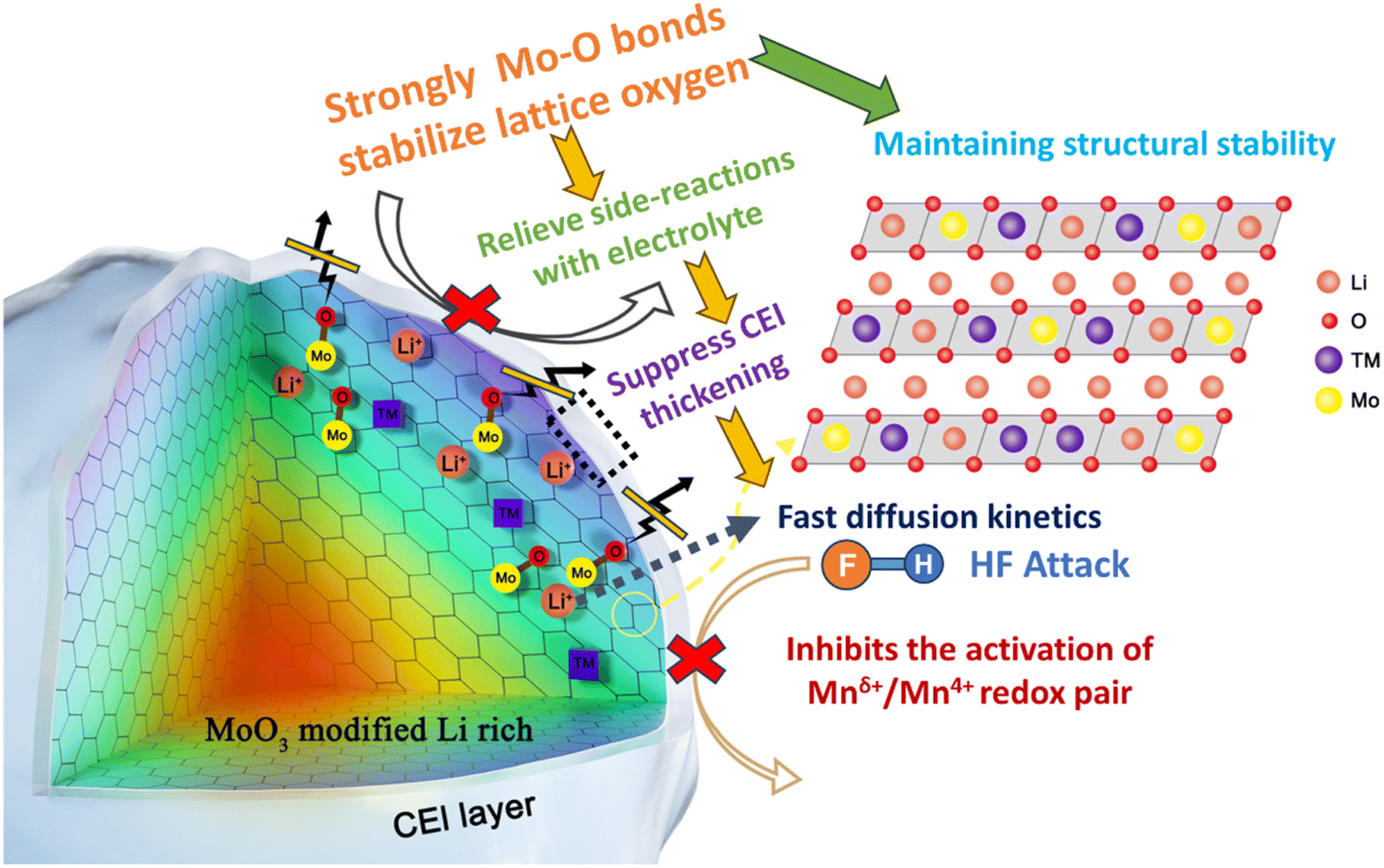 | ||
| Scheme 1 Schematic illustration of the reaction mechanism of strong covalent Mo–O bonds interacting with LLOs. | ||
2. Experimental section
2.1. Material preparation
The cathode material Li1.2[Ni0.13Co0.13Mn0.54]1−xMoxO2 (x = 0, 0.5, 1.0, and 1.5 mol%) was prepared by a high-temperature solid-phase method, and the process is shown schematically in Fig. S1.† The stoichiometric ratios of Ni0.167Co0.167Mn0.666CO3 precursor, Li2CO3 and MoO3 were ball-milled in ethanol for 2 h and then dried. The obtained powder mixture was calcined at 550 °C for 5 h and then calcined at 875 °C for 12 h in air. Here x = 0 corresponds to the unmodified sample, labeled LRP. The modified samples were labeled as LR-Mo0.5, LR-Mo1.0, and LR-Mo1.5 depending on the amount of Mo added. Among them, Li2CO3 (99.5%) was obtained from Ganfeng Lithium, the precursor from Zhongwei Advanced Material Co. Ltd. and MoO3 powder (50 nm) from Shanghai Chaowei Nanotechnology Co. Ltd.2.2. Material characterizations
The crystal structure of the powder samples was characterized by X-ray diffraction (XRD, PANalytical Empyrean), and the diffraction data of the samples were collected in the range of 10–80° using a radiation source with Cu Kα. The Rietveld refinement was performed using the GSAS (General Structure Analysis System) program. Field emission scanning electron microscopy (FESEM; MIRA4 LMH) and energy-dispersive spectrometry (EDS) were used to observe the surface morphology of the cathode particles, the elemental distribution, and the surface state of the materials. To further investigate the effects of Mo modification, the coin cell was disassembled in an argon-filled glovebox, and then the obtained electrode was rinsed with dimethyl carbonate. The microstructure of the material was characterized by transmission electron microscopy (TEM, Tecnai G2 F20). The chemical environment on the surface of the material was analyzed by X-ray photoelectron spectroscopy (XPS, Thermo ESCALAB 250XI). Two-dimensional transmission X-ray microscopy (TXM) tests were conducted using 18-ID FXI beamline at National Synchrotron Light Source II of Brookhaven National Laboratory. During the two-dimensional spectral projection scanning, the energy scans were performed at the absorbing K-edge of Mn on the 100 cycled electrode, with incident X-ray energies ranging from 6200 to 7340 eV for Mn, and complete XANES images were obtained.2.3. Electrochemical measurements
The electrochemical tests were performed using CR2025 coin-type cells. The cathode was prepared by mechanically mixing 80 wt% active substance, 10 wt% acetylene black and 10 wt% polyvinylidene fluoride (PVDF) in a N-methyl-2-pyrrolidone (NMP) solvent. The obtained slurry was uniformly coated on an aluminum foil and dried in a vacuum oven at 120 °C for 12 hours, and then the foil was punched into circular discs with a diameter of 12 mm and the mass loading is about 2.3 mg cm−2. The coin cell was assembled in an argon-filled glovebox (oxygen and water contents are lower than 0.01 ppm). The counter electrode is a lithium foil with a diameter of 16 mm and a thickness of 1 mm. The separator is Celgard 2400, and the electrolyte is TC-EXW-1B from Jiujiang Tianci High-tech Materials Co. Ltd. The electrochemical performance was carried out using a Wuhan Land-CT2001A system for constant current charge–discharge testing in the voltage range of 2.0–4.8 V. A coin cell is charged at a multiplication rate of 1C, which corresponds to a current density of 250 mA g−1. Cyclic voltammetry (CV) measurements were performed using an electrochemical workstation (CHI600D, Shanghai Chenhua, China) at different scan rates under a voltage window of 2.0–4.8 V. Electrochemical impedance spectroscopy (EIS) measurement was performed in the frequency range of 0.01 Hz to 100 kHz with an amplitude of 5 mV.3. Results and discussion
3.1. Structure and morphological characterization
The crystal structures of LRP and Mo-doped samples were analyzed by XRD, and the obtained spectra are shown in Fig. 1(a). The major diffraction peaks correspond to the typical hexagonal layered α-NaFeO2 structure with a space group R![[3 with combining macron]](https://www.rsc.org/images/entities/char_0033_0304.gif) m, and the weak diffraction peaks between 20 and 25° correspond to the superlattice structure of Li2MnO3 with the space group C2/m. The results indicate that the presence of Mo did not change the crystal structure of the material. Meanwhile, the (006)/(012) and (018)/(110) peaks of the samples are both significantly split, indicating that both LRP and Mo-doped samples are in a well-layered structure. Due to the low content of Mo elements, no significant other peaks were observed in the plots.
m, and the weak diffraction peaks between 20 and 25° correspond to the superlattice structure of Li2MnO3 with the space group C2/m. The results indicate that the presence of Mo did not change the crystal structure of the material. Meanwhile, the (006)/(012) and (018)/(110) peaks of the samples are both significantly split, indicating that both LRP and Mo-doped samples are in a well-layered structure. Due to the low content of Mo elements, no significant other peaks were observed in the plots.
 | ||
| Fig. 1 (a) XRD patterns of LRP and Mo-doped samples. (b) Expanded reflection of (003) and (104). Rietveld refinements of (c) LRP and (d) LR-Mo1.0. SEM images of (e) LRP and (f) LR-Mo1.0. (g–j) EDS images of LR-Mo1.0. | ||
To obtain the detailed structural information of LRP and LR-Mo1.0, their XRD data were subjected to Rietveld refinement, as shown in Fig. 1(c and d). The calculated lattice parameters are shown in Table S1.† The basic principle of elemental substitution is that the ionic radii are similar or have the same valence state.22 Since the ionic radius of Mo6+ (0.059 nm) and that of the TM are closer, the introduction of Mo element will occupy the TM site. The Mo–O bond energy is about 604 kJ mol−1, which is significantly higher than that of Ni–O, Co–O, or Mn–O bonds, which are 495 kJ mol−1, 537 kJ mol−1, or 461 kJ mol−1. In addition, the stronger the bond energy, the shorter the bond length. Mo–O has a bond length of 1.70–1.92 Å, while Ni–O, Co–O, and Mn–O have shorter bond lengths of 1.92–2.10 Å, 1.89–2.00 Å, and 1.90–2.10 Å. Obviously Mo–O has a shorter bond length.25,26 As a result, the XRD diffraction peak of LR-Mo1.0 has a slight shift to the right and the cell parameters of the material are slightly decreased.
The morphology of the samples was observed using SEM, and the images of LRP and LR-Mo1.0 are shown in Fig. 1(e and f). Both are spherical particles composed of nanosized primary particles, which are fine polygonal particles and densely packed. The difference is that the LRP surface is denser, while the LR-Mo1.0 surface forms a loose and porous structure. This gives the material surface more active sites and promotes the de-embedding of lithium ions.27 However, when the addition of Mo was too high, a radial structure was formed on the surface of LR-Mo1.5, as shown in Fig. S2.† It seems that the introduction of Mo elements affects the crystal growth of LLOs, and the more the Mo doping, the smaller the primary particle. The mapping results of Ni, Co, Mn, and Mo in Fig. 1(g–j) indicate that all elements are uniformly distributed in LR-Mo1.0.
3.2. Electrochemical performances
We investigated the effect of different Mo additions on the electrochemical performance of LLOs. The cycling performance and initial charge–discharge curves in the voltage range of 2.0–4.8 V are shown in Fig. 2(a and b). It can be seen that the initial discharge specific capacity of the Mo-modified sample does not change significantly, but the capacity retention significantly exceeds that of the pristine sample. When x = 1.0 mol%, the electrochemical stability of the material is optimal. After 100 cycles, the discharge capacity of the LR-Mo1.0 sample was 177.4 mA h g−1, while 157.8 mA h g−1 was remained barely in the LRP, improving 12.4%. Therefore, based on the preliminary analysis and electrochemical evaluation, LR-Mo1.0 was selected for the further study, and the subsequent discussion will mainly focus on LRP and LR-Mo1.0.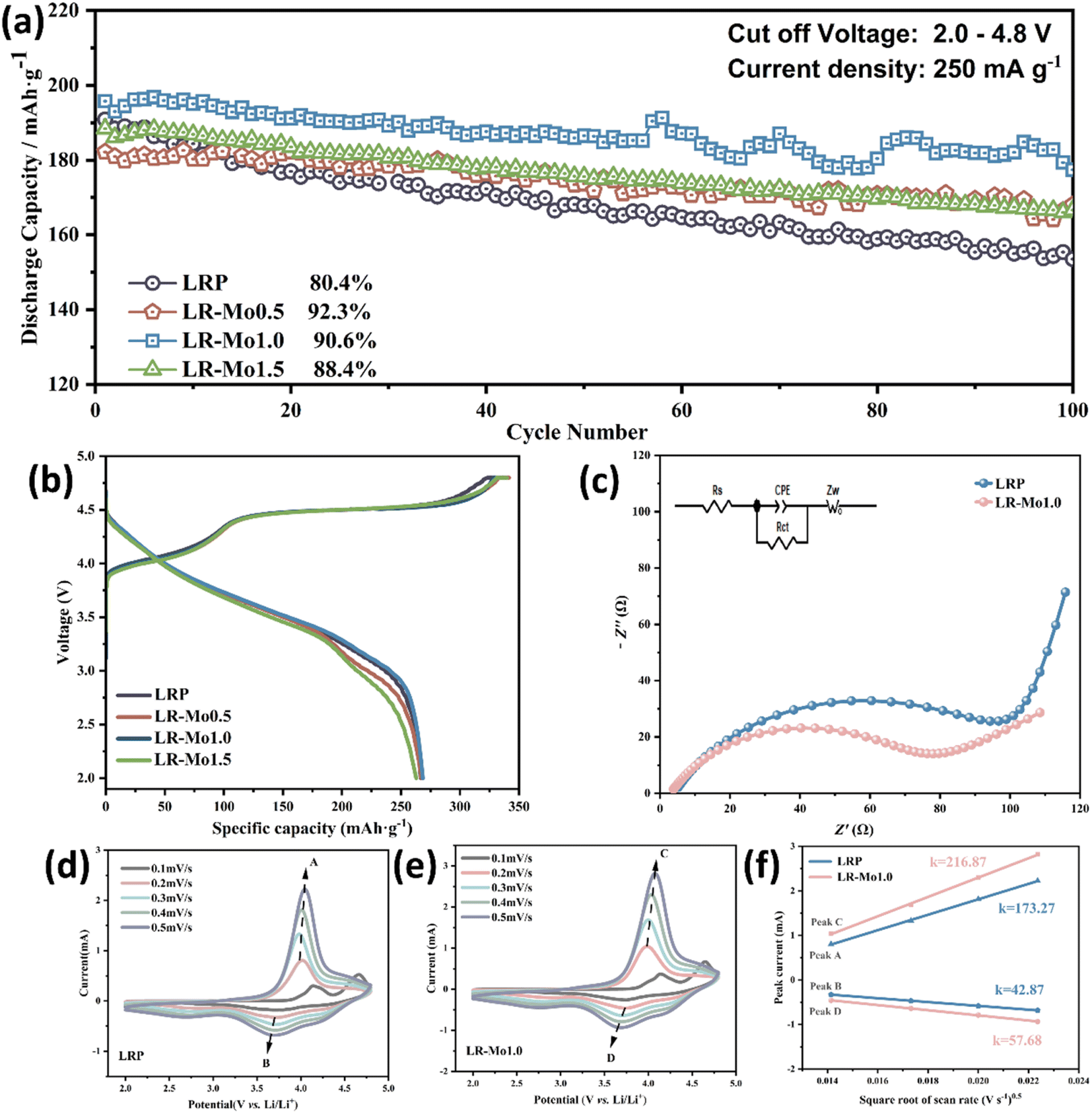 | ||
| Fig. 2 Electrochemical performance of LRP and Mo-doped samples. (a) Cycling performance of discharge capacity. (b) Initial charge–discharge curves at 0.1C. (c) Nyquist diagrams of LRP and LR-Mo1.0. CV curves of (d) LRP and (e) LR-Mo1.0 at different scan rates. (f) Slope of the fitted line for the current peak at different scan rates in LRP and LR-Mo1.0. | ||
To further investigate the effect of Mo modification on the kinetic mechanism of LLOs, we performed electrochemical impedance spectroscopy (EIS) tests on LRP and LR-Mo1.0 before cycling. The data were fitted according to the equivalent circuit, and the Nyquist curve fitting results are shown in Fig. 2(c), where Rs is the migration impedance of Li+ in the electrolyte, Rct is the charge-transfer resistance, and Zw is the Warburg impedance, which corresponds to the Li+ diffusion in the bulk phase.28 The Rct value of LR-Mo1.0 is 65.1 Ω, lower than that of LRP, 100.8 Ω. The decrease in impedance indicates that the strong Mo–O covalent binding can effectively promote the charge transfer process, shorten the diffusion distance of lithium ions, and increase the transport rate of lithium ions.
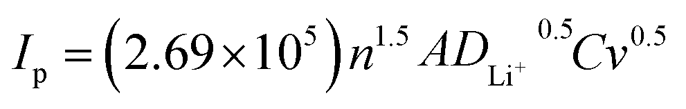
To reveal the effect of strongly covalent Mo–O on the Li+ de-embedding kinetics, CV tests were carried out on LRP and LR-Mo1.0 with different scanning speeds in the voltage range of 2.0–4.8 V. As shown in Fig. 2(d and e), the CV curves of both samples have similar shapes, and at a scanning rate of 0.1–0.5 mV s−1, accompanied by an increase in the scanning speed, all oxidation peaks slightly shifted to higher potentials, while all reduction peaks shifted slightly to lower potentials. In addition, the peak current (Ip) shows an obvious linear relationship with the square root of the sweep rate (v0.5), as shown in Fig. 2(f). The good fitting results indicate that the electrochemical behavior of the two samples is the diffusion-controlled process. Therefore, the lithium ion diffusion coefficient DLi+ (cm2 s−1) can be calculated according to the Randles–Sevcik equation as follows:28,29
3.3. Strong Mo–O covalent binding reduces oxygen release
Differences in local configurations also significantly affect redox processes in oxide cathodes. In conventional well-layered oxide anodes, such as LiNiO2, there is only one type of localized environment for oxygen ions, and all the O ions happen to be coordinated by three TM ions and three lithium ions, and Li–O–TM is the only configuration. In contrast, both Li–O–Li and Li–O–TM configurations are present in LLOs.30 Among them, the unstable oxygen electrons extracted from the Li–O–Li structure are the source of the anionic redox capacity.21,31 When lithium ions are deeply released from the lattice framework, the weakened TM–O coordination bond combines with the O–O bond of the dimer, prompting cations to migrate to form TMLi–VTM pairs and accelerating material failure.32 When Mo occupies some of the TM sites in the LLOs, it changes the local environment for oxygen ions. Strong covalent Mo–O bonds hold O firmly in the lattice, preventing the release of oxygen species into the electrolyte for reaction.The XPS spectra of LRP and LR-Mo1.0 at the first charge to a potential of 4.8 V are shown in Fig. 3(a and b). The characteristic peak at 531.0 eV corresponds to oxygen ions with a lower electron cloud density than O2−, mainly attributed to the presence of On−.33,34 The reduction of On− species in LR-Mo1.0 suggests that elemental Mo binds strongly to oxygen, scavenging charged oxygen radicals, reducing oxygen release, and making the material surface less reactive.
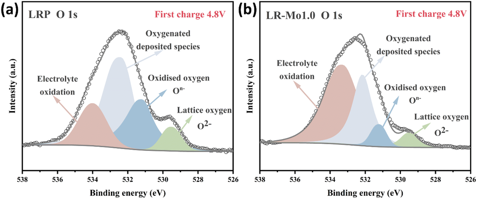 | ||
| Fig. 3 O 1s XPS spectra of (a) LRP and (b) LR-Mo1.0 electrode charged to 4.8 V. | ||
The irreversible loss of oxygen in LLOs reduces the Mn valence state, due to the fact that when oxygen On− leaves, it must leave behind the −ve charge. This leads to the reduction of Mn during subsequent cycling (Mn4+ → Mnδ+, δ < 4).35 In the initial cycle, the main capacity contribution comes from oxygen and nickel, cobalt in TM. However, the oxygen contribution continues to diminish with continued oxygen loss in the cycle. At this point, the Mnδ+/Mn4+ redox pair is activated due to the reduction of Mn, resulting in a steady increase in the capacity contribution of Mn. Although the participation of Mn in the redox reaction can compensate for the capacity loss due to the oxygen release and maintain the overall capacity of the cycling process. However, Mn plays a structure stabilizing role in LLOs, participating in the reaction at the expense of destabilizing the crystal structure and tending to trigger irreversible phase transitions.36
In propose of exploring the impact of Mo modification on the distribution of Mn's valence state at the particle level, ex situ two-dimensional tomography and transmission X-ray microscopy (TXM) serve as ideal tools for these evaluations.37 The TXM images of LRP and LR-Mo1.0 after 100 cycles are shown in Fig. 4(a and b). The valence state of Mn on LR-Mo1.0 particles is strongly higher than that of LRP, indicating that the reduction of Mn is suppressed and less Mn participate in the redox reaction. This is also a direct corroboration of the fact that LR-Mo1.0 has reduced the oxygen loss during cycling and the reversible capacity of oxygen is well maintained. Spatially resolved TXM XANES data can also be used to quantify the diversity of Mn oxidation states through the edge position in the histogram. As shown in Fig. 4(c), it can be clearly visualized that the overall valency of Mn in LR-Mo1.0 particles is higher than that of LRP. It indicates that the presence of more stable high-valency Mn ions maintains the structural stability well and inhibits the unfavorable phase transition from layered to spinel. For a more visual comparison, the particle-scale Mn spectrum is plotted in Fig. 4(d), which explains that the position of the Mn K-edge of LR-Mo1.0 is at a higher X-ray energy. As shown in Fig. S3,† the cycled LRP particles display a lower Mn valence on the surface than that in the bulk phase. This is because oxygen release issues typically start from the surface. Interestingly, the exact opposite is observed in LR-Mo1.0. The Mn with a higher valency appears on the particle's surface, which implies that the presence of strong Mo–O bonds inhibits the release of O and suppresses the reduction of Mn, while also constructing a more stable surface. Therefore, it can be concluded that oxygen release in the charge process is the root cause that leads to Mn participating redox in the following cycling. It is well known that Mn is not a stable element in the present lithium-ion battery system, and the voltage decay and capacity drop is not unexpected.
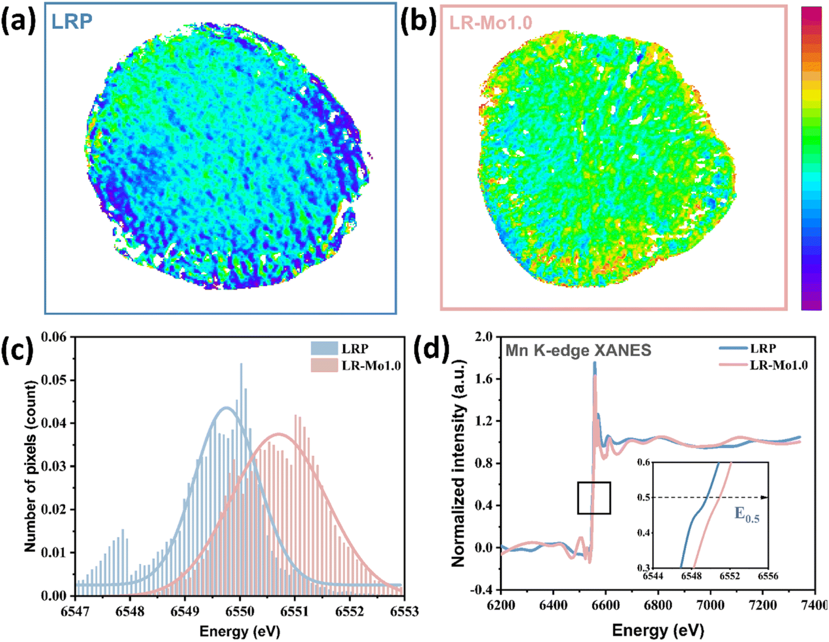 | ||
| Fig. 4 (a and b) Two-dimensional TXM-XANES mapping at the Mn K-edge of cycled LRP and LR-Mo1.0 particles at the discharged state. (c) Histogram line profiles of LRP and LR-Mo1.0. (d) Mn K-edge XANES of LRP and LR-Mo1.0. | ||
3.4. Multifaceted impacts of oxygen release inhibition on LLOs
A significant issue resulting from the irreversible oxygen release from LLOs is the phase transition. During the cycling process, the TM migrates to octahedral positions within the lithium layers, resulting in a structural transition from a layered phase to a spinel phase.38,39 The phase transition schematic is shown in Fig. 5(g and h). The strongly covalent Mo–O bond acts as a stationary column and raises the migration barrier for the TM transferring. In turn, the irreversible phase transition of LLOs from the layered phase to the spinel phase during cycling was suppressed. At this point, the material maintains good structural stability even in the presence of severe delithiation.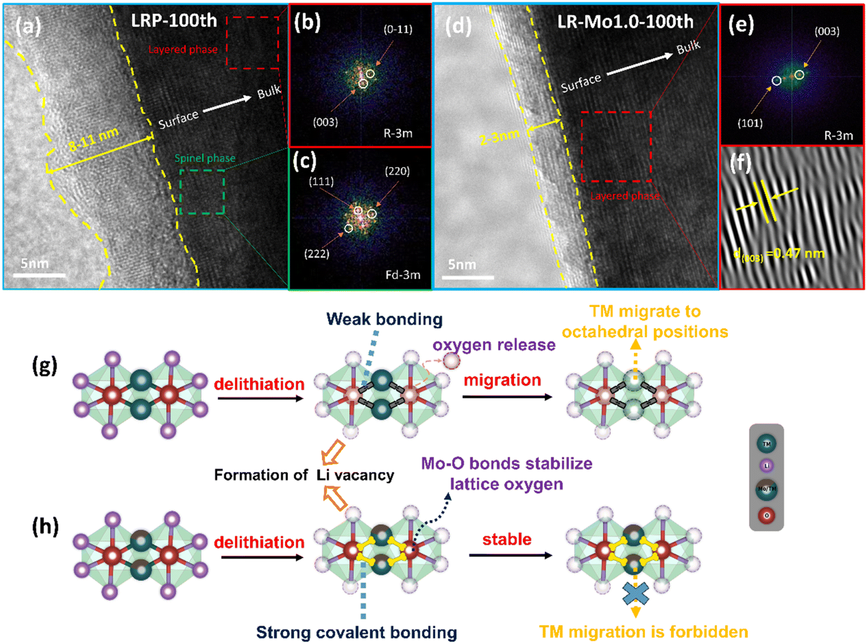 | ||
| Fig. 5 HRTEM images for the 100th cycles of (a) LRP and (d) LR-Mo1.0; (b and c) FFT patterns of the corresponding area in (a); (e and f) FFT and IFFT patterns of the corresponding area in (d); schematic diagrams of the phase evolution routes for (g) LRP and (h) LR-Mo1.0. | ||
High-resolution transmission electron microscopy (HRTEM) characterization can be used to analyze the microstructure of LRP and LR-Mo1.0. The 100th cycled coin cell was disassembled in an attempt to further examine the changes in the material structure. Fig. 5 shows the HRTEM image of the cycled electrode, and it can be seen that extensive domains of spinel structure were formed on the surface of the LRP sample after 100 cycles. In addition, the Mo-modified lithium-rich cathode still maintains a good layered structure from the surface to the bulk, without generating a spinel phase or rock salt phase, which suggests that strong covalent Mo–O bonds inhibit the transition of the layered phase to unfavorable spinel and rock salt phases.
To more thoroughly study the positive effects of Mo–O bonding on enhancing the structural stability of the materials, the LRP and LR-Mo1.0 electrodes were performed by XRD and SEM after cycling. From Fig. S4(a),† it is clearly that the XRD intensity of the LRP electrode decreased significantly, and the (003) peak was shifted by 0.25° to the low-angle direction, indicating that the layered structure of the lithium-rich oxides was deeply damaged during the cycling process. In contrast, the (003) peak of the LR-Mo1.0 sample is shifted by only 0.06°, which implies that the strongly covalent Mo–O bond effectively enhances the structural stability of the material by reducing the irreversible oxygen release. Meanwhile, in Fig. S4(b),† the spherical secondary particles of the LRP samples were fragmented after cycling. This is due to the fact that the volume of the cathode particle will inevitably expand and contract during the charging and discharging process, and the dense surface cannot release the stress in time.
Another beneficial effect of the inhibition of oxygen release on LLOs is the reduction of the reaction of oxygen species with the electrolyte, resulting in the formation of a stable CEI. From Fig. 5(a and d), it can be observed that the thickness of the CEI formed on the LRP electrode is about 8–11 nm and the distribution is extremely uneven. It is to be noted that a thick CEI layer may hinder the transport of lithium ions on the cathode, resulting in slow kinetics. By comparison, the CEI on the surface of the LR-Mo1.0 electrode is only 2–3 nm thick and uniformly distributed, providing a fast lithium ion transport channel.
To gain more insight into the chemical composition and properties of CEI, ex situ XPS analysis was performed to detect the C, O, F, and P signals on the electrode surface, and the results are displayed in Fig. 6(a–h). The decrease in the –C![[double bond, length as m-dash]](https://www.rsc.org/images/entities/char_e001.gif) O– peak of the LR-Mo1.0 sample indicates that the organic buildup on the LLO surface is suppressed. The –CO– characteristic peaks on the O 1s spectra mainly originate from the organic matter such as ROCO2Li formed by the decomposition of the electrolyte at high voltages.40 The powerful covalent Mo–O bond firmly anchors O in surface, which is aggressive to the electrolyte, preventing the release of highly reactive oxygen species.
O– peak of the LR-Mo1.0 sample indicates that the organic buildup on the LLO surface is suppressed. The –CO– characteristic peaks on the O 1s spectra mainly originate from the organic matter such as ROCO2Li formed by the decomposition of the electrolyte at high voltages.40 The powerful covalent Mo–O bond firmly anchors O in surface, which is aggressive to the electrolyte, preventing the release of highly reactive oxygen species.
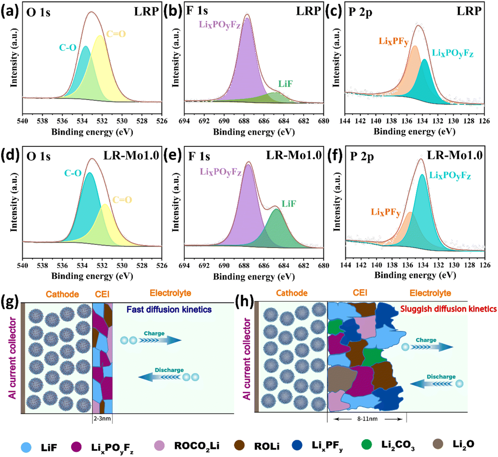 | ||
| Fig. 6 Ex situ XPS spectra of C 1s, O 1s, F 1s and P 2p for (a–c) LRP and (d–f) LR-Mo1.0. Schematic diagram of CEI formation of (g) LRP and (h) LR-Mo1.0. | ||
Meanwhile, compared to the LRP sample, the characteristic intensity peaks of the LiF at the F 1s spectra and the LixPOyFz at the P 2p spectra for the LR-Mo1.0 are significantly higher. This is attributed to the immobilization of oxygen, which effectively suppresses the accumulation of organic compounds, which results in the formation of more film-friendly LiF and LixPOyFz species on the surface of the LR-Mo1.0 electrode. LiF is currently recognized as an inorganic material conducive to the formation of a robust and stable CEI layer, which is able to remain stable during cycling without continuous dissolution/deposition and subsequently inhibit the uneven thickening of CEI during charging and discharging. The LiF-rich CEI exhibits a high degree of electronic insulation, which passivates the electrode surface and prevents further undesirable reactions from occurring due to direct contact between the active material and the electrolyte.41 Additionly, LixPOyFz species also favor the formation of stable CEI.42
Based on the above-mentioned results, a simple schematic diagram is depicted in Fig. 6(g and h). The strong covalent Mo–O bonds contributed to the formation of this robust, uniform-thickness, LiF-rich and inorganic CEI on the electrode surface of LLOs leading to high ionic conductivity.
4. Conclusions
In summary, the strong covalent Mo–O bonds in lithium-rich layered oxides (LLOs) are able to reduce the energy level and the number of O 2p nonhybridized states, which effectively reduces the irreversible release of O and thus inhibits the unfavorable transformation of the layered to spinel phase. Meanwhile, the enhanced stability of lattice oxygen can effectively inhibit unfavorable interfacial reactions between the electrode and the electrolyte, which leads to the formation of a robust, uniform-thickness, LiF-rich CEI on the surface. Apparently, it can decrease the electrochemical impedance of the cell, increase the ionic conductivity of the material, and improve the kinetics of lithium ion migration. Therefore, the strong covalent Mo–O bonding contributes to the realization of LLO cathode materials with high discharge specific capacity and good cycling stability.Conflicts of interest
There are no conflicts of interest to declare.Acknowledgements
This work was financially supported by the National Natural Science Foundation of China (Grant 51772333, 51874358). Moreover, the authors would like to thank KW-ST Lab (https://www.kewei-scitech.com) for their X-ray photoelectron spectroscopy (XPS) measurements equipped with a vacuum transfer accessory. The authors would like to thank Hunan Navi New Materials Technology for their assistance with test analysis. The authors would like to thank Shiyanjia Lab (https://www.shiyanjia.com) for their characterization services.References
- Z. Li, H. Li, S. Cao, W. Guo, J. Liu, J. Chen, C. Guo, G. Chen, B. Chang, Y. Bai and X. Wang, Chem. Eng. J., 2023, 452, 139041 CrossRef CAS.
- E. Wang, D. Xiao, T. Wu, B. Wang, Y. Wang, L. Wu, X. Zhang and H. Yu, Battery Energy, 2023, 2, 20220030 CrossRef CAS.
- K.-Q. Geng, M.-Q. Yang, J.-X. Meng, L.-F. Zhou, Y.-Q. Wang, S. Dmytro, Q. Zhang, S.-W. Zhong and Q.-X. Ma, Tungsten, 2022, 4, 323–335 CrossRef.
- Y. Feng, C. Li, S. Li and L. Ai, IOP Conf. Ser. Earth Environ. Sci., 2018, 153, 022025 CrossRef.
- X.-w. Lai, G.-r. Hu, Z.-d. Peng, Y.-b. Cao, K. Du and Y.-x. Liu, J. Cent. South Univ., 2022, 29, 1463–1478 CrossRef CAS.
- Q. Li, D. Ning, D. Wong, K. An, Y. Tang, D. Zhou, G. Schuck, Z. Chen, N. Zhang and X. Liu, Nat. Commun., 2022, 13, 1123 CrossRef CAS PubMed.
- Y. Wang, S. Cai, Z. Sun, Q. Hou, H. Huang, J. Cheng, J. Fan, M. Zheng and Q. Dong, Small, 2021, 18, 2106072 CrossRef PubMed.
- M. Hu, X. Pang and Z. Zhou, J. Power Sources, 2013, 237, 229–242 CrossRef CAS.
- S. Zhang, J. Wang, H. Liu, W. Zhang, L. Sun, Y. Du, H. J. Seifert and T. Lei, Nanoscale, 2022, 14, 15034–15047 RSC.
- Y. Sun, Q. Wu and L. Zhao, Ceram. Int., 2019, 45, 1339–1347 CrossRef CAS.
- Y. Hao, F. Yang, D. Luo, J. Tian and Z. Shan, J. Energy Chem., 2018, 27, 1239–1246 CrossRef.
- N. Srivastava, S. K. Singh, D. Meghnani, R. Mishra, R. K. Tiwari, A. Patel, A. Tiwari and R. K. Singh, ACS Appl. Energy Mater., 2022, 5, 12183–12195 CrossRef CAS.
- H. Zheng, X. Han, W. Guo, L. Lin, Q. Xie, P. Liu, W. He, L. Wang and D.-L. Peng, Mater. Today Energy, 2020, 18, 100518 CrossRef CAS.
- Y. L. Huo, Y. J. Gu, Z. L. Chen, X. Y. Ma, Y. G. Xiong, H. F. Zhang, F. Z. Wu and X. Y. Dai, ACS Appl. Mater. Interfaces, 2023, 15, 18450–18462 CrossRef CAS.
- M. Farahmandjou, S. Zhao, W.-H. Lai, B. Sun, P. H. L. Notten and G. Wang, Nano Mater. Sci., 2022, 4, 322–338 CrossRef CAS.
- S. Kang, D. Choi, H. Lee, B. Choi and Y. M. Kang, Adv. Mater., 2023, 35, 2211965 CrossRef CAS PubMed.
- Z. Chen, S. Kang, J. Peng, Y. Cai, Y. Huang, Q. Pan, F. Zheng, H. Wang, Q. Li and S. Hu, ACS Energy Lett., 2022, 8, 417–419 CrossRef.
- S. Y. Kim, C. S. Park, S. Hosseini, J. Lampert, Y. J. Kim and L. F. Nazar, Adv. Energy Mater., 2021, 11, 2100552 CrossRef CAS.
- S. Zhao, K. Yan, J. Zhang, B. Sun and G. Wang, Angew Chem. Int. Ed. Engl., 2021, 60, 2208–2220 CrossRef CAS PubMed.
- Y. Wang, Q. Zhang, Z. C. Xue, L. Yang, J. Wang, F. Meng, Q. Li, H. Pan, J. N. Zhang, Z. Jiang, W. Yang, X. Yu, L. Gu and H. Li, Adv. Energy Mater., 2020, 10, 2001413 CrossRef CAS.
- D. H. Seo, J. Lee, A. Urban, R. Malik, S. Kang and G. Ceder, Nat. Chem., 2016, 8, 692–697 CrossRef CAS PubMed.
- B. Zhang, Y. Zhang, X. Wang, H. Liu, Y. Yan, S. Zhou, Y. Tang, G. Zeng, X. Wu, H. G. Liao, Y. Qiu, H. Huang, L. Zheng, J. Xu, W. Yin, Z. Huang, Y. Xiao, Q. Xie, D. L. Peng, C. Li, Y. Qiao and S. G. Sun, J. Am. Chem. Soc., 2023, 145, 8700–8713 CAS.
- X. Ding, Y. Wang, X. Wang, L. Geng, C. Guo, W. Liu, H. Wang, C. Sun and C. Han, Chem. Eng. J., 2023, 466, 143331 CrossRef CAS.
- Y. Liu, X. Rong, R. Bai, R. Xiao, C. Xu, C. Zhang, J. Xu, W. Yin, Q. Zhang, X. Liang, Y. Lu, J. Zhao, L. Chen and Y.-S. Hu, Nat. Energy, 2023, 8, 1088–1096 CrossRef CAS.
- M. P. Mitoraj and A. Michalak, Struct. Chem., 2012, 23, 1369–1375 CrossRef CAS.
- D. R. Lide, CRC Handbook of Chemistry and Physics, CRC Press, 97th edn, 2016 Search PubMed.
- J. Huang, F. Zhu, Y. Shu, G. Hu, Z. Peng, Y. Cao, J. Jiang, S. Zhang, X. Wang and K. Du, Ceram. Int., 2021, 47, 34611–34618 CrossRef CAS.
- A. E. Shrshr, Y. Dong, M. A. Al-Tahan, X. Kang, H. Guan, X. Zheng and J. Zhang, J. Alloys Compd., 2022, 910, 164917 CrossRef CAS.
- P. Zeng, L. Huang, X. Zhang, Y. Han and Y. Chen, Appl. Surf. Sci., 2018, 427, 242–252 CrossRef CAS.
- Y. Lai, H. Xie, P. Li, B. Li, A. Zhao, L. Luo, Z. Jiang, Y. Fang, S. Chen, X. Ai, D. Xia and Y. Cao, Adv. Mater., 2022, 34, 2206039 CrossRef CAS.
- C. Zhang, B. Wei, M. Wang, D. Zhang, T. Uchiyama, C. Liang, L. Chen, Y. Uchimoto, R. Zhang, P. Wang and W. Wei, Energy Storage Mater., 2022, 46, 512–522 CrossRef.
- W. Zeng, F. Liu, J. Yang, B. Zhang, F. Cao, W. Tian, J. Wang, R. Yu, F. Xia, H. Peng, J. Ma, Z. Wang, S. Mu and J. Wu, Energy Storage Mater., 2023, 54, 651–660 CrossRef.
- M. Sathiya, G. Rousse, K. Ramesha, C. P. Laisa, H. Vezin, M. T. Sougrati, M. L. Doublet, D. Foix, D. Gonbeau, W. Walker, A. S. Prakash, M. Ben Hassine, L. Dupont and J. M. Tarascon, Nat. Mater., 2013, 12, 827–835 CrossRef CAS PubMed.
- L. Fang, M. Chen, K.-W. Nam and Y.-M. Kang, Batteries, 2022, 8, 132 CrossRef CAS.
- Z. Zhu, R. Gao, I. Waluyo, Y. Dong, A. Hunt, J. Lee and J. Li, Adv. Energy Mater., 2020, 10, 2001120 CrossRef CAS.
- E. Hu, X. Yu, R. Lin, X. Bi, J. Lu, S. Bak, K.-W. Nam, H. L. Xin, C. Jaye, D. A. Fischer, K. Amine and X.-Q. Yang, Nat. Energy, 2018, 3, 690–698 CrossRef CAS.
- Y. Xu, E. Hu, F. Yang, J. Corbett, Z. Sun, Y. Lyu, X. Yu, Y. Liu, X.-Q. Yang and H. Li, Nano Energy, 2016, 28, 164–171 CrossRef CAS.
- Q. Li, G. Li, C. Fu, D. Luo, J. Fan and L. Li, ACS Appl. Mater. Interfaces, 2014, 6, 10330–10341 CrossRef CAS PubMed.
- G. Jia, F. Li, J. Wang, S. Liu and Y. Yang, ACS Appl. Mater. Interfaces, 2021, 13, 18733–18742 CrossRef CAS PubMed.
- J. Zeng, D. Guan, W. Wang, X. Tan, Y. Cao, Z. Peng, G. Hu and K. Du, ACS Appl. Energy Mater., 2023, 6, 4238–4248 CrossRef CAS.
- N. Zhang, B. Wang, F. Jin, Y. Chen, Y. Jiang, C. Bao, J. Tian, J. Wang, R. Xu, Y. Li, Q. Lv, H. Ren, D. Wang, H. Liu, S. Dou and X. Hong, Cell Rep. Phys. Sci., 2022, 3, 101197 CrossRef CAS.
- X. Zheng, S. Weng, W. Luo, B. Chen, X. Zhang, Z. Gu, H. Wang, X. Ye, X. Liu, L. Huang, X. Wu, X. Wang and Y. Huang, Research, 2022, 2022, 9754612 CAS.
Footnote |
| † Electronic supplementary information (ESI) available. See DOI: https://doi.org/10.1039/d3ta05649j |
| This journal is © The Royal Society of Chemistry 2024 |