
 Open Access Article
 This Open Access Article is licensed under a Creative Commons Attribution-Non Commercial 3.0 Unported Licence
Hydrogen peroxide assisted synthesis of fluorescent carbon nanoparticles from teak leaves for dye-sensitized solar cells†
Arup Kumer
Roy
 *a,
William
Ghann
b,
Saswata
Rabi
a,
Jackson
Barua
a,
Sumit
Majumder
c,
Ruhul
Amin
d,
M. K. Mohammad
Ziaul Hyder
a and
Jamal
Uddin
*b
*a,
William
Ghann
b,
Saswata
Rabi
a,
Jackson
Barua
a,
Sumit
Majumder
c,
Ruhul
Amin
d,
M. K. Mohammad
Ziaul Hyder
a and
Jamal
Uddin
*b
aDepartment of Chemistry, Chittagong University of Engineering & Technology, Chattogram 4349, Bangladesh. E-mail: arupkumer@cuet.ac.bd
bCenter for Nanotechnology, Department of Natural Sciences, Coppin State University, 2500W. North Ave, Baltimore, MD, USA. E-mail: juddin@coppin.edu
cDepartment of Biomedical Engineering, Chittagong University of Engineering & Technology, Chattogram 4349, Bangladesh
dRadioisotope Production Division, Institute of Nuclear Science and Technology, Atomic Energy Research Establishment, Savar, Dhaka, Bangladesh
First published on 28th February 2024
Abstract
Fluorescent carbon nanoparticles (FCNs) have emerged as promising sensitizers for dye-sensitized solar cells (DSSCs) owing to their unique optical properties and low-cost fabrication. In this study, we synthesized three different types of FCNs, such as hydrogen peroxide (H2O2)-assisted FCNs (FCNH), hydrothermal-assisted FCNs (FCNA), and pyrolysis-assisted (FCNP). Among them, FCNH-based DSSCs exhibited superior fluorescence properties, indicating effective surface oxidation by H2O2. Then we fabricated DSSCs using FCNP, FCNA, and FCNH as sensitizers and evaluated their photovoltaic activity. The results revealed that FCNH-based DSSCs exhibited superior performance compared to FCNP-based and FCNA-based DSSCs with an open circuit voltage (VOC) of 0.43 V, a short circuit current (ISC) of 0.52 mA, and a fill factor (FF) of 0.45. The superior performance of FCNH-based DSSCs can be attributed to the improved charge transfer and fluorescence properties of the FCNs after surface oxidation with H2O2. These findings emphasize the significance of surface oxidation in optimizing the performance of FCNs in DSSCs and suggest the potentiality of FCNH as an efficient sensitizer in renewable energy as well as energy harvesting applications for wearable platforms.
Sustainability spotlightThe unique optical properties and low fabrication cost of fluorescent carbon nanoparticles (FCNs) have made them a promising sensitizer for dye-sensitized solar cells (DSSCs). Typically, concentrated oxidizing acidic solutions, including HNO3, H2SO4, H2SO4/HNO3 mixture and H3PO4, have been used to induce the oxidation of carbon sources, resulting in the formation of carbon nanodots with surface functional moieties, such as carboxylic acids, hydroxyl groups, or carbonyl groups. Teak leaves (Tectona grandis L. f.) were utilized in this study as a natural resource to create affordable, environmentally beneficial H2O2-assisted functionalized carbon nanomaterials (FCNH). The fluorescent carbon nanoparticles (FCNs) were applied in dye sensitized solar cells. The study's findings highlight the importance of surface oxidation in maximizing the performance of functionalized carbon nanomaterials (FCNs) in dye-sensitized solar cells (DSSCs) and point to the possibility of using H2O2-assisted FCNs as an effective sensitizer in energy harvesting and renewable energy applications for wearable platforms. The Sustainable Development Goals (SDGs) of the UN are met by our work: responsible consumption and production (SDG 12), sustainable cities and communities (SDG 11), and industry, innovation, and infrastructure (SDG 9). |
1 Introduction
In recent years, fluorescent carbon nanomaterials (FCNs) have gained considerable attention from researchers due to their unique properties, such as tunability in size, shape, excellent electron conductivity, fluorescence properties, surface chemistry, and optical properties.1–9 These properties make them attractive for a variety of applications, including optoelectronic devices,9,10 wearable sensors,11 drug delivery,12 supercapacitors,13 photocatalysis,14 solar cells,2,5,15,16 bioimaging and biosensing.17–19Various synthesis strategies have been developed for preparing FCNs, including top-down and bottom-up approaches.20,21 Top-down approaches involve the fragmentation of a larger carbon structure using physical or chemical methods, followed by size selection and surface modification. Bottom-up approaches involve the formation of carbon nanoparticles from smaller molecular precursors through chemical reactions. Other methods, such as electrochemical and photochemical synthesis, have also been reported.22 Typically, concentrated oxidizing acidic solutions, including HNO3,23 H2SO4,24 H2SO4/HNO3 mixture,25,26 and H3PO4,27 have been used to induce the oxidation of carbon sources, resulting in the formation of carbon nanodots with surface functional moieties, such as carboxylic acids, hydroxyl groups, or carbonyl groups.
In the last few years, H2O2-assisted quantum dots from different sources, such as graphene,28 sulfur,29 and nitrogen-doped carbon,30 have been synthesized by hydrothermal treatment. In this study, we used teak leaves (Tectona grandis L. f.) as a natural resource to synthesize eco-friendly and cost-effective H2O2-assisted functionalized carbon nanomaterials (FCNH). Teak leaves are a promising source of carbon due to their abundance of various organic compounds.31
Hydrothermal treatment is a cost-effective and convenient one-step approach for producing water-soluble FCNs with a narrow size distribution on a large scale.32 The use of H2O2 as an oxidizer during the synthesis process can incorporate oxygen-containing functional groups onto the surface of the carbon skeleton and improve the aqueous solubility and biocompatibility of the FCNs.33 However, in this study, we also fabricated hydrothermal-assisted FCNs using only deionized (DI) water (referred to as FCNA), and additional FCNs were synthesized by pyrolyzing teak leaves (referred to as FCNP) by using H2O2. It was observed that FCNA exhibited a blue emission color and showed good stability in an aqueous solution under 365 nm UV irradiation, despite the absence of H2O2.
To date, in the field of dye-sensitized solar cells (DSSCs), a limited number of applications of FCNs have been reported.34 In DSSCs, FCNs act as sensitizers, enhancing light absorption in the visible region and thereby improving overall solar cell efficiency.34 Nevertheless, organic dyes, particularly ruthenium (Ru) dyes,35,36 and D–π–A structured porphyrin dyes,34,37–39 have also been used as photosensitizers in DSSCs. Generally, organic-based sensitizers have demonstrated superior performance compared to FCNs. However, due to certain drawbacks associated with organic dyes, such as low stability, time-consuming synthesis process and toxicity, the scientific community has emphasized the need for the development of simple, cost-effective and eco-friendly DSSCs to overcome these limitations.34 From this perspective, the use of non-toxic and environmentally friendly FCNs can potentially contribute towards fabricating DSSCs. In this study, blue emitting FCNs are synthesized from teak leaves to construct DSSCs. To the best of our knowledge, this study represents the first attempt to employ H2O2-assisted FCNs in DSSCs, with results indicating excellent activity compared to traditional FCNs.
2 Experimental section
2.1 Chemicals and apparatus
Analytical grade hydrogen peroxide (30%) was purchased from Sigma-Aldrich. Dried teak tree (Tectona grandis L. f.) leaves were collected near the Chittagong University of Engineering & Technology area in the Chattogram region of Bangladesh. The titanium dioxide (TiO2) powder (Degussa P-25) for the photoanode preparation was acquired from the Institute of Chemical Education, University of Wisconsin–Madison, Department of Chemistry, Madison, WI, USA. Fluorine tin oxide (FTO) conducting glass slides were purchased from Hartford Glass Company, Hartford City, Indiana, USA. Acetone, ethanol, and acetic acid were obtained from Sigma-Aldrich (St. Louis, MS, USA) and used without additional purification. DI water was used throughout all segments in this experiment.2.2 Experimental
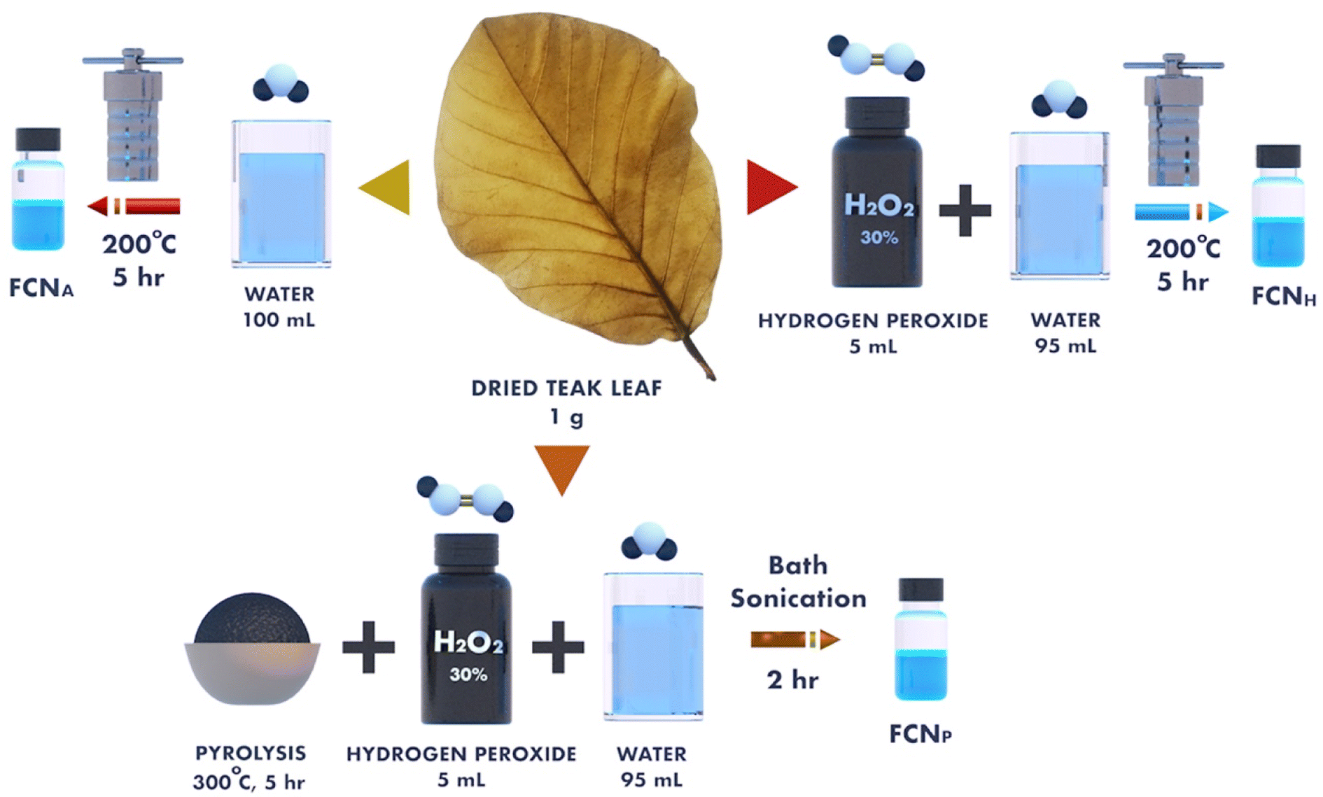 | ||
| Scheme 1 Different synthesis routes of FCNs from dried teak leaves. | ||
2.3 Fabrication of dye sensitized solar cells
The titanium dioxide (TiO2) films were prepared utilizing a previously documented spin-coating technique.40–42 To prepare the working electrode, the fluorine-doped transparent tin oxide (FTO) substrate (Hartford Glass Co., Inc. TEC 7, 1" × 1" × 2.2 mm thickness, Solar) was cleaned with detergent, deionized (DI) water and ethanol using an ultrasonic bath for 30 min. To prepare the titanium dioxide (TiO2) paste, TiO2 powder (Degussa P-25) was initially mixed with glacial acetic acid. Then, the prepared TiO2 paste was applied to the conductive side of FTO using a spin coater and annealed at 450 °C for 30 min.43–45 The substrate was then immersed in FCN solutions (1 mg of FCNs in 1 mL pure water) overnight for sensitization. Loosely bound particles were removed by rinsing with water and ethanol and the photoanode was dried at room temperature. The counter electrode (cathode) was prepared by painting colloidal graphite on the cleaned FTO-coated glass slide and allowed it to dry at room temperature. Finally, to fabricate the DSSCs, the FCN-sensitized slide and the carbon electrodes were put on top of each other and the redox (I−/I3−) electrolyte solution was placed between them.2.4 Characterization and measurements
The fluorescent nanoparticles and the sensitized film's morphology were assessed using field emission scanning electron microscopy (JSM-7100FA JEOL USA, Inc.). Absorption spectroscopy was conducted using a UV-3600 Plus from Shimadzu, MD, USA, while emission spectroscopy measurements were performed with an RF-5301PC from Shimadzu, MD, USA. The zeta potentials of the samples were determined using an SZ-100 series Dynamic Light Scattering Particle Size Distribution Analyzer, HORIBA Instruments Inc., Irvine, CA, USA. Transmission Electron Microscopy (TEM) images were obtained using a JEM-1400 PLUS (JEOL USA, Peabody, Massachusetts, USA). The TiO2 paste was deposited onto FTO glass using a WS-650 Series Spin Processor from Laurell Technologies Corporation, PA, USA. Carbon paint obtained from TED PELLA, INC, USA was used for making cathode slides.2.5 Photovoltaic measurements of DSSCs
The cell performance was evaluated using a 150 W fully reflective solar simulator with standard illumination of air-mass 1.5 global (AM 1.5 G) and an irradiance of 100 mW cm−2 (Sciencetech Inc., London, Ontario, Canada). A GAMRY Instruments Reference 600 Potentiostat/Galvanostat/ZRA (Warminster, PA) was employed for the measurements. Cells were externally biased and the photocurrent generated was measured to determine the current–voltage characteristics of the cells under these conditions. The electrocatalytic performance of the samples was further evaluated by electrochemical impedance spectroscopy (EIS).3 Results and discussion
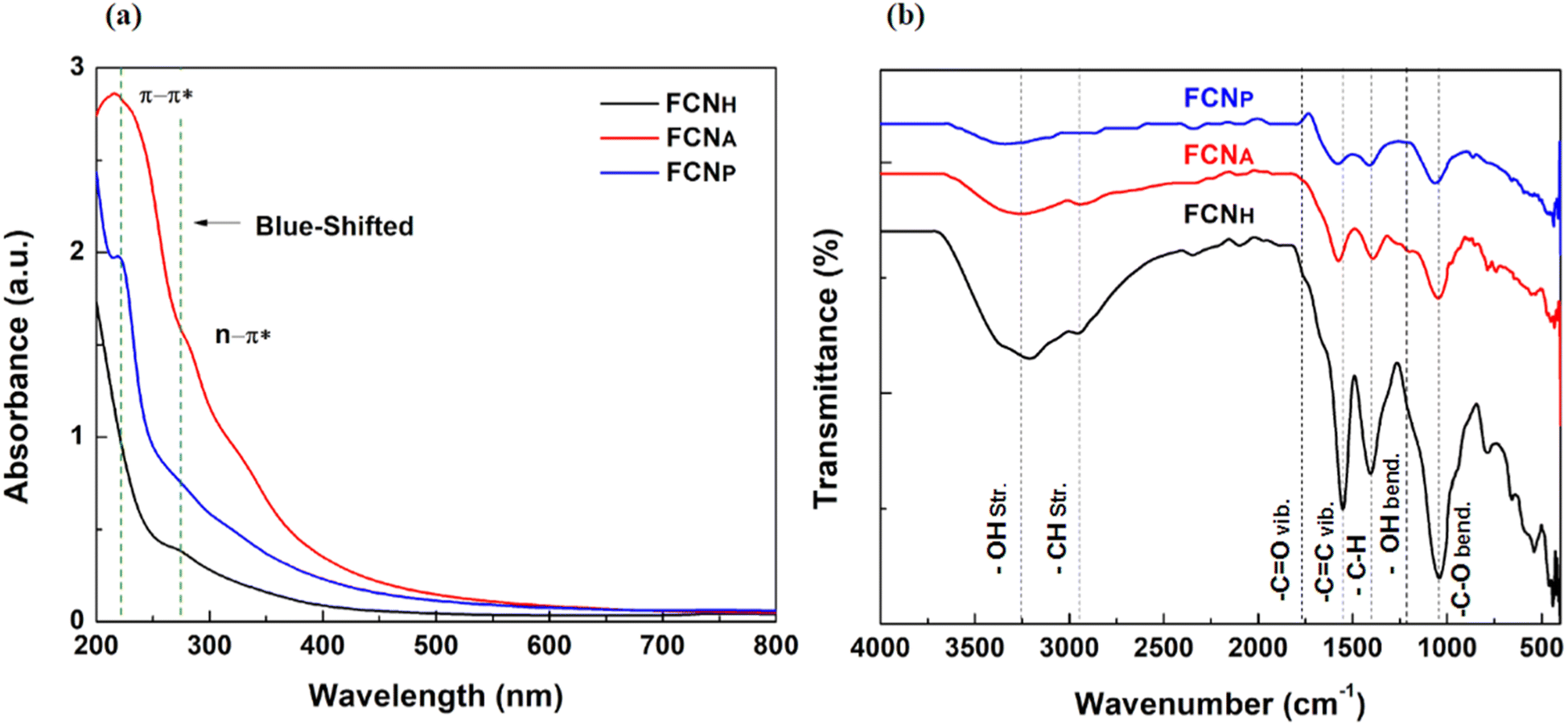
Surface oxidation is a recognized method for enhancing fluorescence in carbon-based materials by introducing oxygen-containing functional groups via the generation of surface defects.46 H2O2 is known to be effective in promoting the generation of these defects, resulting in an abundance of carbonyl and carboxylic groups on the carbon structure, thereby improving the solubility in aqueous solutions.47 The prepared H2O2-supported aqueous solution of FCNH exhibited blue emission under 365 nm UV light and formed stable-colored suspensions in DI water, which is likely due to the larger number of functional groups, such as hydroxyl and carboxylic groups.The UV-vis spectra of all FCNs have been investigated and are presented in Fig. 1a. The spectra showed a weak absorption in the UV region at around 220 nm attributed to the π–π* electronic transition of the sp2 conjugated carbon (C![[double bond, length as m-dash]](https://www.rsc.org/images/entities/char_e001.gif) C) bond48 and a weak absorption peak at around 285 nm due to the functional groups (CO) present on the surface of all FCNs.49 Notably, the absorbance peak position of FCNH shifted towards the blue region compared to the other two FCNs, signifying a larger number of hydroxyl and carboxylic groups incorporated into the carbon structure through oxidation with H2O2.
C) bond48 and a weak absorption peak at around 285 nm due to the functional groups (CO) present on the surface of all FCNs.49 Notably, the absorbance peak position of FCNH shifted towards the blue region compared to the other two FCNs, signifying a larger number of hydroxyl and carboxylic groups incorporated into the carbon structure through oxidation with H2O2.
 | ||
| Fig. 1 (a) UV-vis spectra and (b) FT-IR of the as-synthesized FCNs. | ||
The surface functional groups of the three different types of the synthesized FCNs were investigated using Fourier transform infrared (FTIR) spectroscopy, as presented in Fig. 1b. The FCNH sample exhibited a higher overall peak intensity compared to FCNA and FCNP. All FCNs exhibited identical CC stretching and C–H bending peaks at around 1600 and 1027 cm−1, respectively, attributed to the alkyl hydrocarbon from the teak leaf. The broad signature band peak of –OH stretching at 3200 cm−1 to 3400 cm−1 was detected in all FCNs, confirming the adsorption of water molecules onto sample surfaces, along with an –OH bending peak at around 1390 cm−1. Additionally, a distinguished CO stretching peak was detected at around 1740 cm−1 with high intensity in FCNH, confirming the successful incorporation of a considerable number of oxygen functional groups into the carbon moieties after treatment with H2O2. A superimposed C–H stretching peak of each sample was also observed in the region 2400–2950 cm−1.50
The photoluminescence (PL) spectra were recorded with an excitation wavelength of 340 nm. All synthesized carbon nanoparticles showed fluorescence emission peaks in the blue region, ranging from 430 nm to 435 nm. These results indicated the maximum wavelength at which the emitted fluorescence was observed for all types of FCNs (Fig. 2).
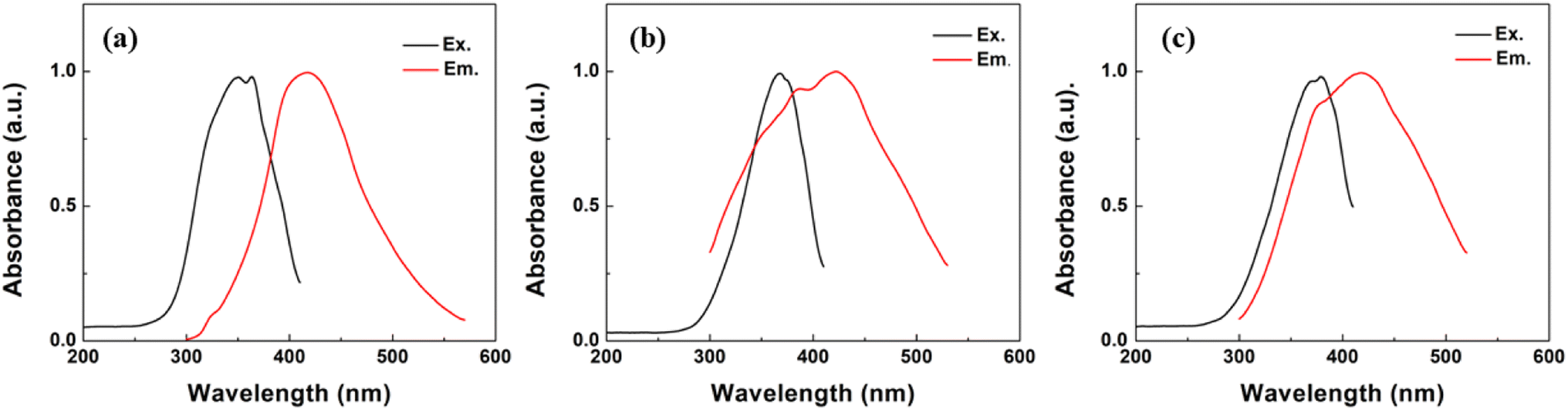 | ||
| Fig. 2 PL spectra of (a) FCNH, (b) FCHA and (c) FCHP. | ||
The zeta potential, which quantifies the surface charge of colloidal particles in a solution, was measured and is presented in Fig. 3. The zeta potential values of the three types of FCNs were assessed using electrophoretic light scattering in an aqueous solution. All samples exhibited negative zeta potential values, confirming negatively charged surfaces. This negative charge is attributed to the presence of oxygenated functional groups on the particle surfaces, which dissociate in the solution and generate negatively charged ions. Among the three samples, FCNH displayed the most negative zeta potential value of −27.7 mV, demonstrating a higher surface negative charge density. The formation of a larger number of functional groups on the particle surface can be attributed to H2O2 treatment. The H2O2 treatment likely facilitated the introduction of more oxygen functionalities, leading to an increased negative charge on the surface. On the other hand, FCNA exhibited a zeta potential value of −11.2 mV, while FCNP showed a more negative value of −23.6 mV, suggesting a notable increase in the negative surface charge compared to FCNA. Notably, FCNH exposed an even stronger negative charge than FCNP, demonstrating a certain level of passivation or resistance toward chemical reactions.51,52 This passivation effect could limit or slow down the functionalization reactions, even with H2O2 treatment. Even though H2O2 introduced oxygenated functional groups, the surface properties of pyrolytic carbon nanoparticles might impede the further incorporation of functional groups, resulting in lower zeta potential values compared to FCNH.53 The observed percentages in EDX (Fig. S1 and Table S1†) reflect the relative abundance of carbon (C) and oxygen (O) atoms within each sample. FCNH exhibited a composition of 79.53% C and 20.47% O atoms, indicating a relatively higher oxygen content. The treatment with H2O2 mainly introduced oxygen-containing functional groups onto the surface of the carbon dots through oxidation reactions. Similarly, FCNA displayed a composition of 81.59% C and 16.52% O, which confirmed the slightly lower oxygen content compared to FCNH. The reduction in oxygen content might be due to the breaking of weaker oxygen-carbon bonds under the high-temperature and pressure conditions of hydrothermal treatment.54 The composition of 42.71% carbon and 14.35% oxygen in FCNP suggests a significant reduction in both carbon and oxygen contents compared to the other treatments. The reduction in both carbon and oxygen contents implies that the pyrolysis process led to the removal of various oxygen-functional groups, as well as a partial decomposition of carbon components, resulting in a composition with relatively lower carbon and oxygen concentrations.
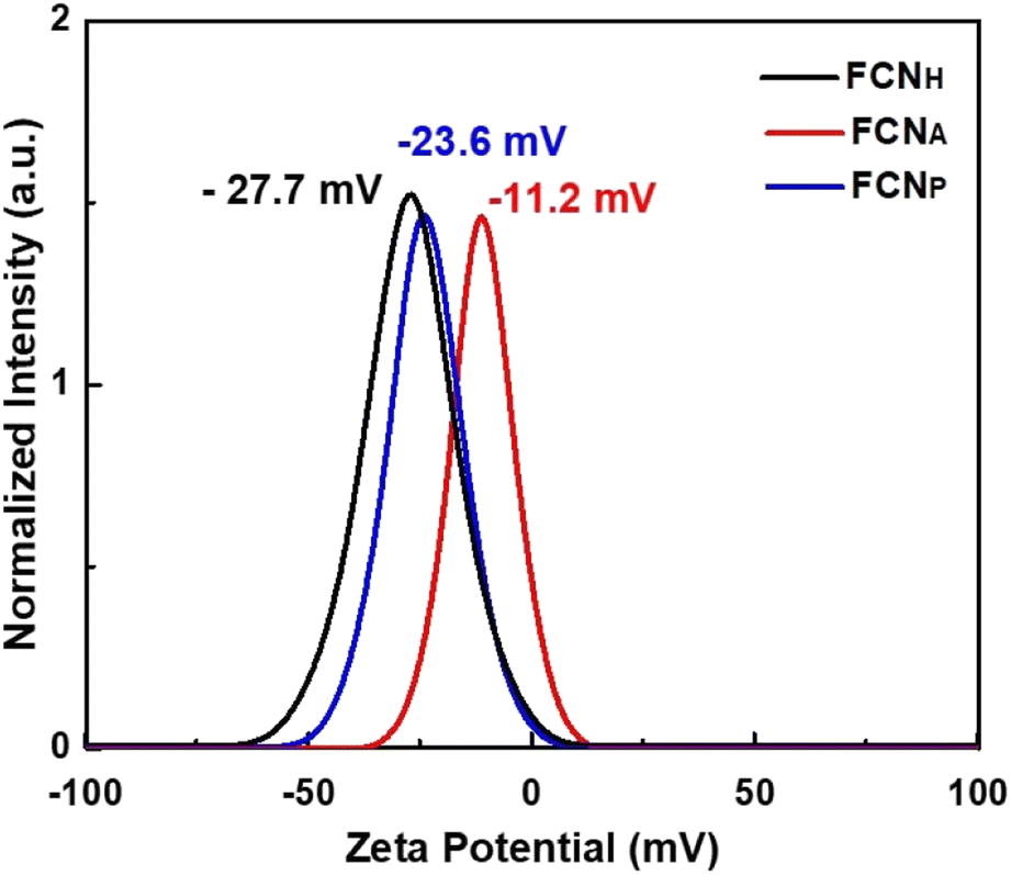 | ||
| Fig. 3 Zeta Potential measurement of all FCNs. | ||
In this study, we also investigated the surface morphology of FCNH using transmission electron microscopy (TEM) and field-emission scanning electron microscopy (FE-SEM). The TEM images displayed individual particles within a size range of 30–40 nm, as depicted in Fig. 4a and b. The FE-SEM results, depicted in Fig. 4c, along with the size distribution measurement (Fig. 4d), corroborated and strengthened the findings from TEM, confirming the presence of nano-sized particles in the sample. Additionally, the FE-SEM images in Fig. S2† revealed that FCNP possessed smaller particle sizes compared to FCNA. Notably, the introduction of H2O2 during the synthesis process resulted in a more significant reduction in particle size for FCNP compared to FCNA. The DLS data (Fig. S3†) obtained in this study were also consistent with the FE-SEM images, supporting the observation that the particle size of FCNP is smaller than that of FCNA.
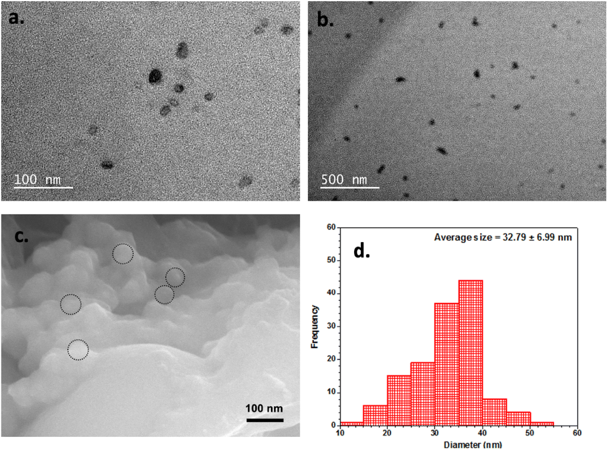 | ||
| Fig. 4 (a) High-resolution TEM image, (b) TEM image, (c) FE-SEM image and (d) particle size distribution histogram of FCNH. | ||
The photoluminescence (PL) lifetime values of the carbon dots were measured for FCNH, FCNA, and FCNP (Fig. 5). For FCNH, the PL lifetime values were 2.20 ns and 8.69 ns, pointing to two distinct decay processes. Similarly, FCNA exhibited two PL lifetime values of 1.28 ns and 7.07 ns, indicating the presence of two decay processes in its emission behavior. On the other hand, FCNP displayed PL lifetime values of 2.09 ns and 8.57 ns when tested with the N719 dye. Therefore, it can be inferred from the PL lifetime values that FCNH has a longer PL lifetime compared to FCNA and FCNP, proposing a lower rate of non-radiative recombination (Table 1). This characteristic potentially contributes to the enhanced solar-to-electric power conversion efficiency in the FCNH-based DSSCs. Conversely, FCNA and FCNP, with their shorter PL lifetimes, are likely to exhibit higher rates of non-radiative recombination, thus resulting in a lower solar-to-electric power conversion efficiency in the DSSCs that utilized these dyes.
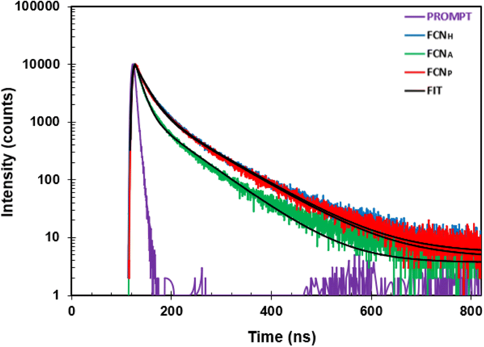 | ||
| Fig. 5 Photoluminescence decay curves at a 420 nm emission wavelength of the FCNs. | ||
| Sample name | Lifetime | |||
|---|---|---|---|---|
| τ 1 (ns) | Std dev. | τ 2 (ns) | Std dev. | |
| FCNH | 2.20 | 1.21 × 10⁻¹¹ | 8.69 | 2.74 × 10⁻¹¹ |
| FCNA | 1.28 | 8.39 × 10⁻¹¹ | 7.07 | 3.03 × 10⁻¹¹ |
| FCNP | 2.09 | 1.32 × 10⁻¹¹ | 8.57 | 3.00 × 10⁻¹¹ |
3.1 Use of FCNs as sensitizers in dye sensitized solar cells
When they are exposed to sunlight, dye molecules (S) absorbed on the TiO2 film absorb photons and are excited from the highest occupied molecular orbital (HOMO) to the lowest unoccupied molecular orbital (LUMO) state as shown in Scheme 2. Upon photoexcitation, the dye species (S*) injects an electron into the conduction band of the TiO2 electrode, leading to its oxidation (S+). The oxidized dye species accepts an electron from the electrolyte (I−), resulting in the restoration of the ground state of the dye (S). The injected electron is then transported through the nano-porous TiO2 film to the FTO layer and further conducted through an external circuit to a load, where it is converted into electrical energy. The electron from the external load subsequently diffuses to the cathode and is transferred to the electrolyte (I3−), thus regenerating the electrolyte system.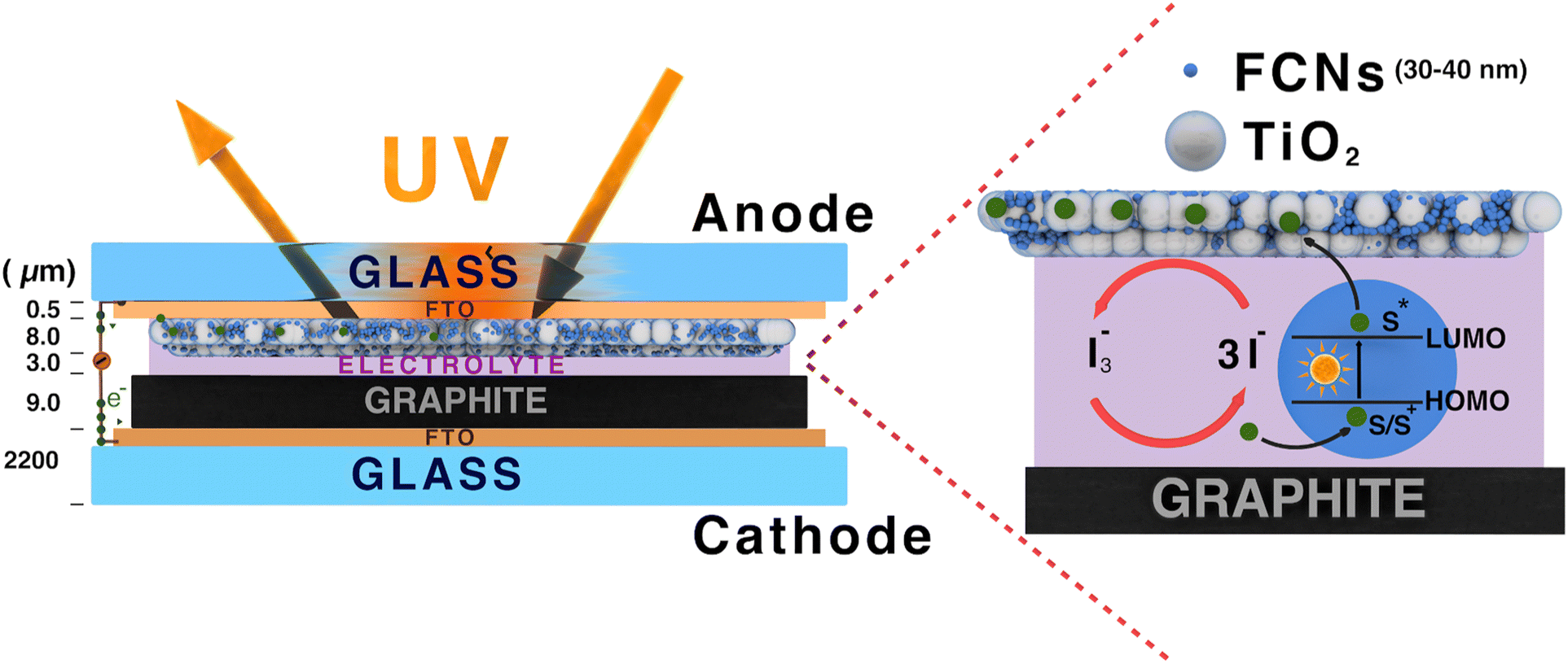 | ||
| Scheme 2 A schematic diagram of the proposed DSSC (not to scale). | ||
The current–voltage (I–V) measurement of the samples was carried out with a standard illumination of air-mass 1.5 global (AM 1.5 G) having an irradiance of 100 mW cm−2. The I–V values of the samples are used to calculate the solar-to-electric energy efficiency of the solar cells. The I–V values of the measurements are displayed in Fig. 6. It was observed that FCNH exhibits promising characteristics as it is evident from its open circuit voltage (VOC) of 0.43 V and short-circuit current (ISC) of 0.52 mA, thus demonstrating the successful functioning of the proposed DSSC (Table 2). Furthermore, the fill factor (FF) of 0.45 obtained from the fabricated DSSC ensures a good electrical contact and low series resistance. However, the power conversion efficiency (PCE) of the fabricated dye sensitized solar cell for FCNH was 0.10%, offering further improvement in terms of light absorption and charge separation efficiency (Table 2).
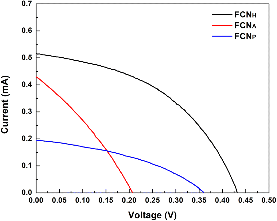 | ||
| Fig. 6 Current–voltage characteristics of DSSCs fabricated from FCNs. | ||
| Sample | Electrolyte | V max | I max | V OC [V] | I SC [mA cm−2] | FF [%] | PCE [%] |
|---|---|---|---|---|---|---|---|
| FCNH | I−/I3− | 0.29 | 0.35 | 0.43 | 0.52 | 0.45 | 0.10 |
| FCNP | 0.11 | 0.25 | 0.21 | 0.43 | 0.31 | 0.03 | |
| FCNA | 0.22 | 0.12 | 0.36 | 0.20 | 0.39 | 0.03 |
3.2 Electrochemical impedance spectroscopy (EIS)
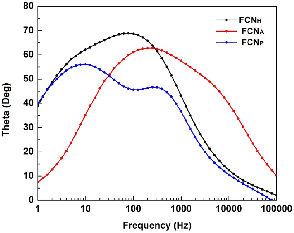
Electrochemical impedance spectroscopy (EIS) studies were carried out to understand the transport and recombination of the photoexcited electrons in the fabricated DSSC. The EIS studies expressed in Bode phase and Nyquist plots are displayed in Fig. 7 and 8, respectively.The charge transfer process at the photoanode/electrolyte interface as well as the electron lifetime (τ) corresponds to the peak frequency in the Bode phase plot (Fig. 7). It is desirable to have a large electron lifetime as in the case of FCNH. Additionally, the inclusion of FCNH leads to a notable decrease in charge transfer resistance, thus resulting in the enhancement of the overall performance of the DSSC.
 | ||
| Fig. 7 Bode plot of the FCN DSSCs. | ||
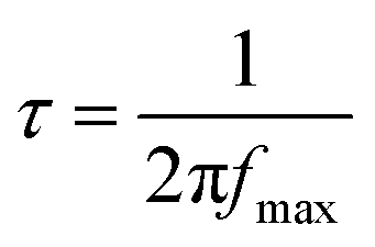
The effective electron lifetime (τ) in a DSSC can be determined by analyzing the maximum frequency in the Bode plot using eqn (1) (ref. 55 and 56)
 | (1) |
The Bode plot analysis of FCNH reveals a peak at 79 Hz, corresponding to an estimated electron lifetime of 2 ms. These findings are depicted in Fig. 8 and summarized in Table 3. The longer electron lifetime observed in FCNH can be associated with a reduced occurrence of recombination within the TiO2 network, thus resulting in an enhanced electron diffusion through lower trapping states. This phenomenon accelerates electron transfer, increases electron density, and ultimately improves the overall performance of the device.
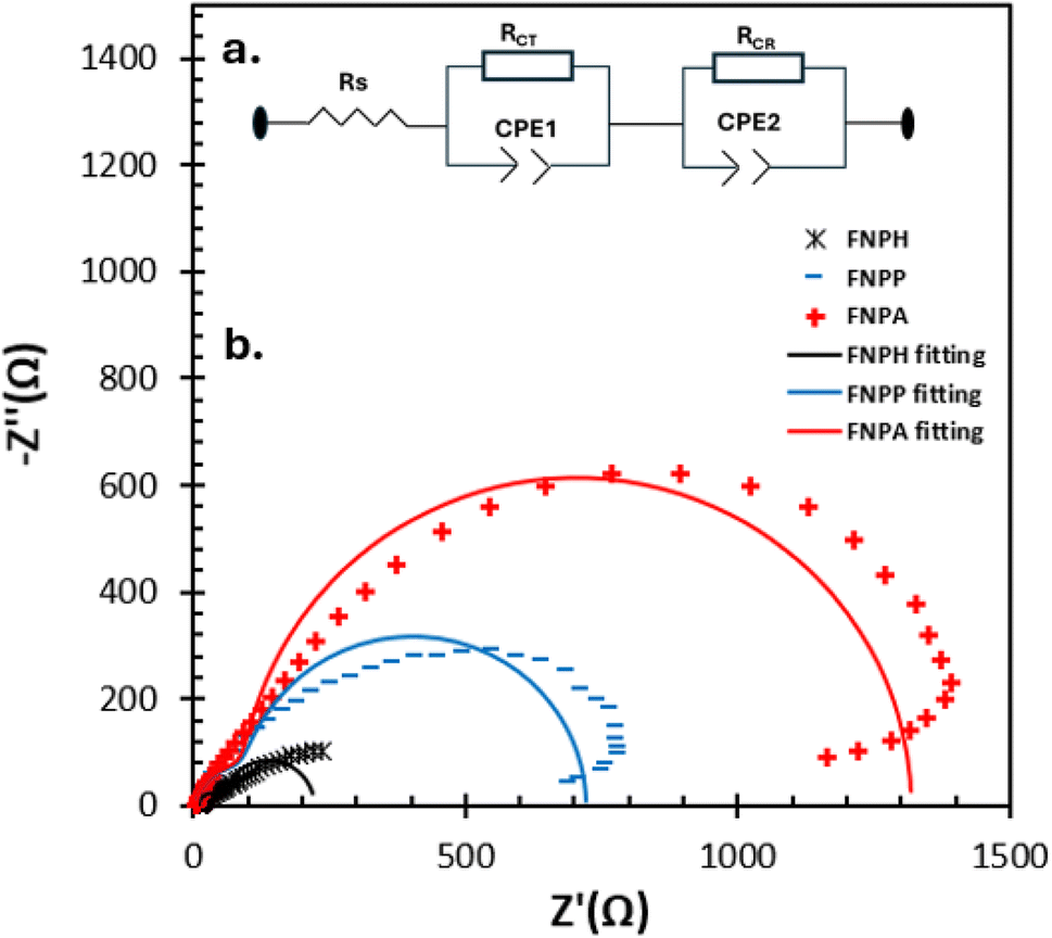 | ||
| Fig. 8 (a) A full cell's equivalent circuit model and (b) matching Nyquist plots of FCNH, FCHA, and FCHP-based DSSCs in the dark at a bias of VOC between 0.1 Hz and 100 Hz with an amplitude of 10 mV. | ||
| Samples | R S (Ω) | R CT (Ω) | R CR (Ω) | τ (ms) |
|---|---|---|---|---|
| FCNH | 47.79 | 11.84 | 161.7 | 2.01 |
| FCNP | 132.7 | 6.398 | 582 | 0.504 |
| FCNA | 140.2 | 6.141 | 1173 | 0.632 |
The Nyquist plots of FCNH, FCHA, and FCHP-based DSSCs measured in the dark at forward bias (VOC) are displayed in Fig. 8b. Each spectrum exhibits two distinct semicircles: the high-frequency region on the left side corresponds to the charge transfer at the electrolyte/counter electrode interface, while the intermediate-frequency region on the right side represents the back charge transfer from the photoanode to the electrolyte.57,58Fig. 8a (inset) shows the equivalent circuit that was used to analyze the EIS spectra. The two interfaces were represented by a parallel combination of a capacitor and a resistance. The device's total series resistance (RS), charge transfer resistance (RCT) at the electrolyte/counter electrode interface, and charge recombination resistance (RCR) at the photoanode/electrolyte interface are depicted in the figure. By fitting an equivalent circuit, the values of RS, RCT, and RCR are obtained and shown in Table 3. In comparison to FCNH (47.79 Ω), a large value of RS (132.7 and 140.2 Ω) in FCHA and FCHP, respectively, suggests a slower charge transport in these two contexts. Although the RCT value in FCNH is marginally higher, all devices' RCT values are consistent because the electrolyte and counter electrode were identical. In FCHA, a noticeably high charge recombination resistance (1173 Ω) was found. This might be due to a gradual recombination in FCHA. The study on the I–V curves of all the DSSCs indicates that FCNH has higher power conversion efficiency compared to FCNA and FCNP. The obtained charge transfer resistance (RCT) is much less in the case of FCNH than FCNA and FCNP, and therefore is clearly associated with the reduced charge recombination and consequently the enhanced electron lifetime due to the abundance of oxygen containing functional groups.59
4 Conclusion
In this study, we have demonstrated an easy H2O2-based FCN synthesis from an economical and available natural precursor teak leaf. H2O2 not only increases the degree of surface oxidation of the carbon framework, but also improves their stability in aqueous solution. The prepared all FCNs showed blue emission fluorescence with high aqueous stability. Then, DSSCs were fabricated using FCNH, FCNA and FCNP as sensitizers and their photovoltaic performance was evaluated. The FCNH-based DSSCs showed superior performance over FCNP-based and FCNA-based DSSCs, achieving an open circuit voltage (VOC) of 0.43 V, a short circuit current (ISC) of 0.52 mA, and a Fill Factor (FF) of 0.45. This enhanced performance of FCNH-based DSSCs was achieved through surface oxidation with H2O2. We anticipate that these bio-based FCNs could provide new insights into the fabrication process of DSSCs. Overall, the development of H2O2-assisted FCNs has opened new avenues for the application of carbon-based nanomaterials in various fields, and their potential uses are still being explored.Conflicts of interest
There are no conflicts to declare.Acknowledgements
The authors express their gratitude to the Chittagong University of Engineering & Technology (CUET) for financial assistance through grant no. CUET/DRE/2018-19/CHEM/016. This research also received funding from Constellation's E2—Energy to Educate grant program and the United States Department of Education through the USDE-SAFRA Title III Grant.References
- W. Ghann, V. Sharma, H. Kang, F. Karim, B. Richards, S. M. Mobin, J. Uddin, M. M. Rahman, F. Hossain, H. Kabir and N. Uddin, The Synthesis and Characterization of Carbon Dots and Their Application in Dye Sensitized Solar Cell, Int. J. Hydrogen Energy, 2019, 44(29), 14580–14587, DOI:10.1016/j.ijhydene.2019.04.072
.
- Y. Yan, J. Gong, J. Chen, Z. Zeng, W. Huang, K. Pu, J. Liu and P. Chen, Recent Advances on Graphene Quantum Dots: From Chemistry and Physics to Applications, Adv. Mater., 2019, 31(21), 1808283, DOI:10.1002/adma.201808283
- J. Liu, Y. Geng, D. Li, H. Yao, Z. Huo, Y. Li, K. Zhang, S. Zhu, H. Wei, W. Xu, J. Jiang and B. Yang, Deep Red Emissive Carbonized Polymer Dots with Unprecedented Narrow Full Width at Half Maximum, Adv. Mater., 2021, 33(38), e2007162, DOI:10.1002/adma.202007162
- K. Jiang, Y. Wang, X. Gao, C. Cai and H. Lin, Facile, Quick, and Gram-Scale Synthesis of Ultralong-Lifetime Room-Temperature-Phosphorescent Carbon Dots by Microwave Irradiation, Angew Chem. Int. Ed. Engl., 2018, 57(21), 6216–6220, DOI:10.1002/anie.201802441
- C. Hu, M. Li, J. Qiu and Y.-P. Sun, Design and Fabrication of Carbon Dots for Energy Conversion and Storage, Chem. Soc. Rev., 2019, 48(8), 2315–2337, 10.1039/C8CS00750K
- S. Zhu, Y. Song, X. Zhao, J. Shao, J. Zhang and B. Yang, The Photoluminescence Mechanism in Carbon Dots (Graphene Quantum Dots, Carbon Nanodots, and Polymer Dots): Current State and Future Perspective, Nano Res., 2015, 8(2) DOI:10.1007/s12274-014-0644-3
- V. C. Hoang, K. Dave and V. G. Gomes, Carbon Quantum Dot-Based Composites for Energy Storage and Electrocatalysis: Mechanism, Applications and Future Prospects, Nano Energy, 2019, 66, 104093, DOI:10.1016/j.nanoen.2019.104093
- Z. Zhang, G. Yi, P. Li, X. Zhang, H. Fan, Y. Zhang, X. Wang and C. Zhang, A Minireview on Doped Carbon Dots for Photocatalytic and Electrocatalytic Applications, Nanoscale, 2020, 12(26), 13899–13906, 10.1039/D0NR03163A
- F. Yuan, Y.-K. Wang, G. Sharma, Y. Dong, X. Zheng, P. Li, A. Johnston, G. Bappi, J. Z. Fan, H. Kung, B. Chen, M. I. Saidaminov, K. Singh, O. Voznyy, O. M. Bakr, Z.-H. Lu and E. H. Sargent, Bright High-Colour-Purity Deep-Blue Carbon Dot Light-Emitting Diodes via Efficient Edge Amination, Nat. Photonics, 2019, 14, 171–176, DOI:10.1038/s41566-019-0557-5
- L. Cui, J. Wang and M. Sun, Graphene Plasmon for Optoelectronics, Rev. Phys., 2021, 6, 100054, DOI:10.1016/j.revip.2021.100054
- S. Majumder, T. Mondal and M. J. Deen, Wearable Sensors for Remote Health Monitoring, Sensors, 2017, 17(1), 130, DOI:10.3390/s17010130
- G. Calabrese, G. De Luca, G. Nocito, M. G. Rizzo, S. P. Lombardo, G. Chisari, S. Forte, E. L. Sciuto and S. Conoci, Carbon Dots: An Innovative Tool for Drug Delivery in Brain Tumors, Int. J. Mol. Sci., 2021, 22(21), 11783, DOI:10.3390/ijms222111783
- L. Song, C. Peng, F. Yang, L. Wang, Y. Jiang and Y. Wang, Surface Spatial Confinement Effect on Mn–Co LDH@Carbon Dots for High-Performance Supercapacitors, ACS Appl. Energy Mater., 2021, 4(5), 4654–4661, DOI:10.1021/acsaem.1c00273
- H. Jung, V. S. Sapner, A. Adhikari, B. R. Sathe and R. Patel, Recent Progress on Carbon Quantum Dots Based Photocatalysis, Front. Chem., 2022, 10, 1–28, DOI:10.3389/fchem.2022.881495
- P. Huang, S. Xu, M. Zhang, W. Zhong, Z. Xiao and Y. Luo, Carbon Quantum Dots Improving Photovoltaic Performance of CdS Quantum Dot-Sensitized Solar Cells, Opt. Mater., 2020, 110, 110535, DOI:10.1016/j.optmat.2020.110535
- J. Zhang, J. Xu and F. Tao, Interface Modification of TiO2 Nanotubes by Biomass-Derived Carbon Quantum Dots for Enhanced Photocatalytic Reduction of CO2, ACS Appl. Energy Mater., 2021, 4(11), 13120–13131, DOI:10.1021/acsaem.1c02760
- J. Wang, R. Sheng Li, H. Zhi Zhang, N. Wang, Z. Zhang and C. Z. Huang, Highly Fluorescent Carbon Dots as Selective and Visual Probes for Sensing Copper Ions in Living Cells via an Electron Transfer Process, Biosens. Bioelectron., 2017, 97, 157–163, DOI:10.1016/j.bios.2017.05.035
- J. Jana, H. J. Lee, J. S. Chung, M. H. Kim and S. H. Hur, Blue Emitting Nitrogen-Doped Carbon Dots as a Fluorescent Probe for Nitrite Ion Sensing and Cell-Imaging, Anal. Chim. Acta, 2019, 1079, 212–219, DOI:10.1016/j.aca.2019.06.064
- J. Hu, F. Tang, Y.-Z. Jiang and C. Liu, Rapid Screening and Quantitative Detection of Salmonella Using a Quantum Dot Nanobead-Based Biosensor, Analyst, 2020, 145(6), 2184–2190, 10.1039/D0AN00035C
- G. Speranza, Carbon Nanomaterials: Synthesis, Functionalization and Sensing Applications, Nanomater., 2021, 11(4), 967, DOI:10.3390/nano11040967
- J. Dhariwal, G. K. Rao and D. Vaya, Recent Advancements towards the Green Synthesis of Carbon Quantum Dots as an Innovative and Eco-Friendly Solution for Metal Ion Sensing and Monitoring, RSC Sustainability, 2024, 2(1), 11–36, 10.1039/D3SU00375B
- C.-I. Wang, W.-C. Wu, A. P. Periasamy and H.-T. Chang, Electrochemical Synthesis of Photoluminescent Carbon Nanodots from Glycine for Highly Sensitive Detection of Hemoglobin, Green Chem., 2014, 16(5), 2509–2514, 10.1039/C3GC42325E
- Y.-P. Sun, B. Zhou, Y. Lin, W. Wang, K. A. S. Fernando, P. Pathak, M. J. Meziani, B. A. Harruff, X. Wang, H. Wang, P. G. Luo, H. Yang, M. E. Kose, B. Chen, L. M. Veca and S.-Y. Xie, Quantum-Sized Carbon Dots for Bright and Colorful Photoluminescence, J. Am. Chem. Soc., 2006, 128(24), 7756–7757, DOI:10.1021/ja062677d
- G.-H. Oh, B.-S. Kim, Y. Song and S. Kim, Acid Treatment to Tune the Optical Properties of Carbon Quantum Dots, Appl. Surf. Sci., 2022, 605, 154690, DOI:10.1016/j.apsusc.2022.154690
- H. Peng and J. Travas-Sejdic, Simple Aqueous Solution Route to Luminescent Carbogenic Dots from Carbohydrates, Chem. Mater., 2009, 21(23), 5563–5565, DOI:10.1021/cm901593y
- A. K. Roy, S.-M. Kim, P. Paoprasert, S.-Y. Park and I. In, Preparation of Biocompatible and Antibacterial Carbon Quantum Dots Derived from Resorcinol and Formaldehyde Spheres, RSC Adv., 2015, 5(40), 31677–31682, 10.1039/C5RA01506E
- C. J. Jeong, A. K. Roy, S. H. Kim, J.-E. Lee, J. H. Jeong, I. In and S. Y. Park, Fluorescent Carbon Nanoparticles Derived from Natural Materials of Mango Fruit for Bio-Imaging Probes, Nanoscale, 2014, 6(24), 15196–15202, 10.1039/C4NR04805A
- H. Feng, H. Dong, B. Lei, Y. Xiao, H. Hu, H. Zhan, Y. Liu and M. Zheng, One-Pot H2O2-Assisted Hydrothermal Carbonization for the Synthesis of Fluorescent Graphene Quantum Dots Derived from Sewage Sludge, Sci. Adv. Mater., 2016, 8(5), 948–955, DOI:10.1166/sam.2016.2653
- H. Wang, Z. Wang, Y. Xiong, S. V. Kershaw, T. Li, Y. Wang, Y. Zhai and A. L. Rogach, Hydrogen Peroxide Assisted Synthesis of Highly Luminescent Sulfur Quantum Dots, Angew. Chem., Int. Ed., 2019, 58(21), 7040–7044, DOI:10.1002/anie.201902344
- Z. Zhang, S. Xu and P. Wu, H2O2-Assisted Hydrothermal Process: A Green, Versatile Route to Synthesize Size-Controllable Nitrogen-Doped Fluorescent Carbon Nanoparticles from Natural Macromolecules, Part. Part. Syst. Charact., 2015, 32(2), 176–181, DOI:10.1002/ppsc.201400136
- S. M. B. Asdaq, N. Nayeem, Abida, Md. T. Alam, S. I. Alaqel, M. Imran, E.-W. E. Hassan and S. I. Rabbani,
Tectona Grandis L.f: A Comprehensive Review on Its Patents, Chemical Constituents, and Biological Activities, Saudi J. Biol. Sci., 2022, 29(3), 1456–1464, DOI:10.1016/j.sjbs.2021.11.026
- S. Perumal, R. Atchudan, T. N. J. I. Edison and Y. R. Lee, Sustainable Synthesis of Multifunctional Carbon Dots Using Biomass and Their Applications: A Mini-Review, J. Environ. Chem. Eng., 2021, 9(4), 105802, DOI:10.1016/j.jece.2021.105802
- S. P. Teong, X. Li and Y. Zhang, Hydrogen Peroxide as an Oxidant in Biomass-to-Chemical Processes of Industrial Interest, Green Chem., 2019, 21(21), 5753–5780, 10.1039/C9GC02445J
- N. Gao, L. Huang, T. Li, J. Song, H. Hu, Y. Liu and S. Ramakrishna, Application of Carbon Dots in Dye-Sensitized Solar Cells: A Review, J. Appl. Polym. Sci., 2020, 137(10), 48443, DOI:10.1002/app.48443
- H. Ozawa, T. Sugiura, T. Kuroda, K. Nozawa and H. Arakawa, Highly Efficient Dye-Sensitized Solar Cells Based on a Ruthenium Sensitizer Bearing a Hexylthiophene Modified Terpyridine Ligand, J. Mater. Chem. A, 2016, 4(5), 1762–1770, 10.1039/C5TA10393B
- C.-G. Wu, Ruthenium-Based Complex Dyes for Dye-Sensitized Solar Cells, J. Chin. Chem. Soc., 2022, 69(8), 1242–1252, DOI:10.1002/jccs.202200225
- J.-M. Ji, H. Zhou and H. K. Kim, Rational Design Criteria for D–π–A Structured Organic and Porphyrin Sensitizers for Highly Efficient Dye-Sensitized Solar Cells, J. Mater. Chem. A, 2018, 6(30), 14518–14545, 10.1039/C8TA02281J
- Y. Zhang, T. Higashino and H. Imahori, Molecular Designs, Synthetic Strategies, and Properties for Porphyrins as Sensitizers in Dye-Sensitized Solar Cells, J. Mater. Chem. A, 2023, 11(24), 12659–12680, 10.1039/D2TA09264F
- J.-M. Ji, H. Zhou, Y. K. Eom, C. H. Kim and H. K. Kim, 14.2% Efficiency Dye-Sensitized Solar Cells by Co-Sensitizing Novel Thieno[3,2-b]Indole-Based Organic Dyes with a Promising Porphyrin Sensitizer, Adv. Energy Mater., 2020, 10(15), 2000124, DOI:10.1002/aenm.202000124
- O. Aduroja, M. Jani, W. Ghann, S. Ahmed, J. Uddin and F. Abebe, Synthesis, Characterization, and Studies on Photophysical Properties of Rhodamine Derivatives and Metal Complexes in Dye-Sensitized Solar Cells, ACS Omega, 2022, 7(17), 14611–14621, DOI:10.1021/acsomega.1c06772
- D. Kabir, T. Forhad, W. Ghann, B. Richards, M. M. Rahman, Md. N. Uddin, Md. R. J. Rakib, M. H. Shariare, F. I. Chowdhury, M. M. Rabbani, N. M. Bahadur and J. Uddin, Dye-Sensitized Solar Cell with Plasmonic Gold Nanoparticles Modified Photoanode, Nano-Struct. Nano-Objects, 2021, 26, 100698, DOI:10.1016/j.nanoso.2021.100698
- F. Saadmim, T. Forhad, A. Sikder, W. Ghann, M. M. Ali, V. Sitther, A. J. S. Ahammad, M. A. Subhan and J. Uddin, Enhancing
the Performance of Dye Sensitized Solar Cells Using Silver Nanoparticles Modified Photoanode, Molecules, 2020, 25(17), 4021, DOI:10.3390/molecules25174021
- W. Ghann, H. Kang, T. Sheikh, S. Yadav, T. Chavez-Gil, F. Nesbitt and J. Uddin, Fabrication, Optimization and Characterization of Natural Dye Sensitized Solar Cell, Sci. Rep., 2017, 7(1), 41470, DOI:10.1038/srep41470
- W. E. Ghann, H. Kang, J. Uddin, F. A. Chowdhury, S. I. Khondaker, M. Moniruzzaman, M. H. Kabir and M. M. Rahman, Synthesis and Characterization of Reduced Graphene Oxide and Their Application in Dye-Sensitized Solar Cells, ChemEngineering, 2019, 3(1), 7, DOI:10.3390/chemengineering3010007
- W. Ghann, H. Kang, E. Emerson, J. Oh, T. Chavez-Gil, F. Nesbitt, R. Williams and J. Uddin, Photophysical Properties of Near-IR Cyanine Dyes and Their Application as Photosensitizers in Dye Sensitized Solar Cells, Inorg. Chim. Acta, 2017, 467, 123–131, DOI:10.1016/j.ica.2017.08.001
- H. Ding, X.-H. Li, X.-B. Chen, J.-S. Wei, X.-B. Li and H.-M. Xiong, Surface States of Carbon Dots and Their Influences on Luminescence, J. Appl. Phys., 2020, 127(23), 231101, DOI:10.1063/1.5143819
- C. Shen, Y. Wen, X. Kang and W. Liu, H2O2-Induced Surface Modification: A Facile, Effective and Environmentally Friendly Pretreatment of Chitosan for Dyes Removal, Chem. Eng. J., 2011, 166(2), 474–482, DOI:10.1016/j.cej.2010.10.075
- K. Asghar, M. Qasim and D. Das, One-Pot Green Synthesis of Carbon Quantum Dot for Biological Application, AIP Conf. Proc., 2017, 1832(1), 050117, DOI:10.1063/1.4980350
- J. Tan, J. Zhang, W. Li, L. Zhang and D. Yue, Synthesis of Amphiphilic Carbon Quantum Dots with Phosphorescence Properties and Their Multifunctional Applications, J. Mater. Chem. C, 2016, 4(42), 10146–10153, 10.1039/C6TC03027K
- Z. Qian, J. Zhou, J. Chen, C. Wang, C. Chen and H. Feng, Nanosized N-Doped Graphene Oxide with Visible Fluorescence in Water for Metal Ion Sensing, J. Mater. Chem., 2011, 21(44), 17635–17637, 10.1039/C1JM13430B
- L. Pustahija and W. Kern, Surface Functionalization of (Pyrolytic) Carbon—An Overview, C, 2023, 9(2), 38, DOI:10.3390/c9020038
- Z. Xu, M. He, X. Xu, X. Cao and D. C. W. Tsang, Impacts of Different Activation Processes on the Carbon Stability of Biochar for Oxidation Resistance, Bioresour. Technol., 2021, 338, 125555, DOI:10.1016/j.biortech.2021.125555
- L. Ginés, S. Mandal, Ashek-I-Ahmed, C.-L. Cheng, M. Sow and O. A. Williams, Positive Zeta Potential of Nanodiamonds, Nanoscale, 2017, 9(34), 12549–12555, 10.1039/C7NR03200E
- S. Liu, Q. Zhou, K. Zhu, J. Yang, L. Feng, Q. Zhang, X. Weng and J. Zhang, Characteristics and Evolution Mechanism of Three Phase Products of Lignite by Hydrothermal Treatment Dewatering, ACS Omega, 2022, 7(43), 38641–38649, DOI:10.1021/acsomega.2c04080
- S. I. Cho, H. K. Sung, S.-J. Lee, W. H. Kim, D.-H. Kim and Y. S. Han, Photovoltaic Performance of Dye-Sensitized Solar Cells Containing ZnO Microrods, Nanomaterials, 2019, 9(12), 1645, DOI:10.3390/nano9121645
- X. Chen, Y. Tang and W. Liu, Efficient Dye-Sensitized Solar Cells Based on Nanoflower-like ZnO Photoelectrode, Molecules, 2017, 22(8), 1284, DOI:10.3390/molecules22081284
- R. Govindaraj, M. S. Pandian, P. Ramasamy and S. Mukhopadhyay, Sol–Gel Synthesized Mesoporous Anatase Titanium Dioxide Nanoparticles for Dye Sensitized Solar Cell (DSSC) Applications, Bull. Mater. Sci., 2015, 38(2), 291–296, DOI:10.1007/s12034-015-0874-3
- K. Sharma, V. Sharma and S. S. Sharma, Dye-Sensitized Solar Cells: Fundamentals and Current Status, Nanoscale Res. Lett., 2018, 13(1), 381, DOI:10.1186/s11671-018-2760-6
- M. J. Ju, I.-Y. Jeon, K. Lim, J. C. Kim, H.-J. Choi, I. T. Choi, Y. K. Eom, Y. J. Kwon, J. Ko, J.-J. Lee, J.-B. Baek and H. K. Kim, Edge-Carboxylated Graphene Nanoplatelets as Oxygen-Rich Metal-Free Cathodes for Organic Dye-Sensitized Solar Cells, Energy Environ. Sci., 2014, 7(3), 1044–1052, 10.1039/C3EE43732A
Footnote |
| † Electronic supplementary information (ESI) available. See DOI: https://doi.org/10.1039/d3su00452j |
| This journal is © The Royal Society of Chemistry 2024 |