
 Open Access Article
 This Open Access Article is licensed under a
 Creative Commons Attribution 3.0 Unported Licence
Angle-resolved optical spectroscopy of photonic cellulose nanocrystal films reveals the influence of additives on the mechanism of kinetic arrest†
Thomas G.
Parton
 ab,
Richard M.
Parker
a,
Sonja
Osbild
a,
Silvia
Vignolini
*ab and
Bruno
Frka-Petesic
*ac
ab,
Richard M.
Parker
a,
Sonja
Osbild
a,
Silvia
Vignolini
*ab and
Bruno
Frka-Petesic
*ac
aYusuf Hamied Department of Chemistry, University of Cambridge, Lensfield Road, CB2 1EW, UK. E-mail: sv319@cam.ac.uk; bf284@cam.ac.uk
bMax Planck Institute of Colloids and Interfaces, Science Park Golm, 14476 Potsdam, Germany
cInternational Institute for Sustainability with Knotted Chiral Meta Matter (WPI-SKCM2), Hiroshima University, 1-3-1 Kagamiyama, Higashi-Hiroshima, Hiroshima 739-8526, Japan
First published on 3rd April 2024
Abstract
Cellulose nanocrystals (CNCs) are rod-like nanoparticles whose chiral self-assembly into photonic films has been promoted as a sustainable source of colouration. Upon drying, an aqueous CNC suspension passes through two regimes: first, a liquid phase, where the CNCs self-organise into a cholesteric liquid crystal, followed by a kinetically-arrested phase, where the helicoidal structure compresses upon loss of solvent, resulting in a solid film with vibrant structural colour. The transition between these two regimes plays an important role in the visual appearance of photonic CNC films, but details on when and how kinetic arrest occurs have remained elusive. In this work, we combine angle-resolved optical spectroscopy of photonic films (approx. 100 vol% CNC) with a model for compressed helicoidal structures to retrieve the suspension conditions during kinetic arrest (approx. 10 vol% CNC). This analysis indicates a shift in the mechanism of kinetic arrest from a glass transition at lower ionic strength to gelation at higher ionic strength, explaining the trends in domain size and film colour. In contrast, neutral additives (glucose, poly(ethylene glycol)) appear to primarily reduce the compression upon drying without affecting cholesteric behaviour, as supported by a general analytical model. These findings deepen our understanding of CNC co-assembly with various commonly-used additives, enabling better control over the production of multifunctional structurally coloured materials.
1 Introduction
In the pursuit of more sustainable functional materials, the natural world provides both inspiration for structural designs and a renewable supply of biomaterials. Cellulose, as the most abundant biopolymer on the planet, is an especially promising resource in this regard. Acid hydrolysis of natural cellulose (e.g. wood pulp, cotton) yields elongated, negatively-charged nanoparticles known as cellulose nanocrystals (CNCs).1,2 Above a threshold concentration, CNCs can form a cholesteric mesophase,3,4 where the CNCs locally align within an overall left-handed helicoidal configuration with a micron-scale pitch.5 This chiral arrangement can then be preserved upon drying to produce solid films with a submicron periodicity that exhibit structural colour. The self-assembly of CNCs into photonic films thus offers a scalable route to produce bio-sourced and biodegradable optical materials.4Numerous strategies to control the colour of photonic CNC films using additives have been reported: for instance, increasing the electrolyte concentration of the initial suspension leads to a blue-shift in film colour,6 while a red-shift can be achieved by co-assembly of CNCs with non-volatile neutral additives, including small molecules such as glucose7–9 or glycerol,10–12 and polymers such as hydroxypropyl cellulose (HPC)13–15 and poly(ethylene glycol) (PEG),15–17 among many others.4 In some cases, the colour-shifting effects of additives can be ascribed to their impact on the pitch in suspension,18 while the effect of other additives on the cholesteric mesophase is unclear.7 In general, however, the periodicity of a photonic film depends not only on the pitch of the initial near-equilibrium cholesteric phase, but also on the onset of kinetic arrest (KA), after which the decrease in pitch upon increasing the CNC volume fraction results from a geometric compression of the drying structure.7,19 While numerous studies have explored the KA transition at fixed CNC concentration, both for isotropic,20–23 and anisotropic suspensions,24–27 the influence of additives on KA in drying CNC suspensions and the consequences for the visual appearance of the resulting films have not previously been systematically explored.
In this work, we investigate the influence of additives on the visual appearance of photonic CNC films. The optical response of the films was characterised using angle-resolved optical spectroscopy (AROS) and polarised optical microscopy (POM), and analysed using a recently developed model of pitch compression in photonic CNC films.28–30 This analysis offers a way to estimate suspension properties at the onset of KA, most notably the cholesteric pitch and CNC volume fraction, and thus provides evidence that KA in cholesteric CNC suspensions can occur either by a colloidal glass transition or by colloidal gelation depending on the ionic strength of the suspension. The influence of non-volatile additives, namely glucose and poly(ethylene glycol), is further explained by a combination of the reduced geometric compression of the structure upon drying29 and the solubility of the additives. These findings clarify the self-assembly mechanisms by which the cholesteric pitch and the resulting colours of the final films are selected, which is highly relevant to the applications of photonic CNC films as bio-sourced optical materials.
1.1 Overview of CNC self-assembly for photonic films
The evolution of aqueous colloidal suspensions of CNCs upon drying is summarised in Fig. 1(a). While CNCs in dilute suspension (ΦCNC ≲ 1 vol%) exhibit isotropic particle orientation Fig. 1(a)-(i), the elongated, rod-like morphology of CNCs causes them to spontaneously form a cholesteric (chiral nematic) liquid crystal phase above a critical concentration (typically 1–5 vol%, depending on the CNC aspect ratio).3,5 The cholesteric phase first appears as condensed droplets, known as tactoids, within the isotropic phase (Fig. 1(a)-(ii)). The CNCs comprising each tactoid are locally aligned within an overall left-handed helicoidal structure (Fig. 1(b)), with a periodicity given by the pitch P (i.e., the distance over which particle orientation undergoes a full 360° rotation). As the CNC concentration increases further, these tactoids grow and coalesce until the suspension becomes a polydomain cholesteric (Fig. 1(a)-(iii)).31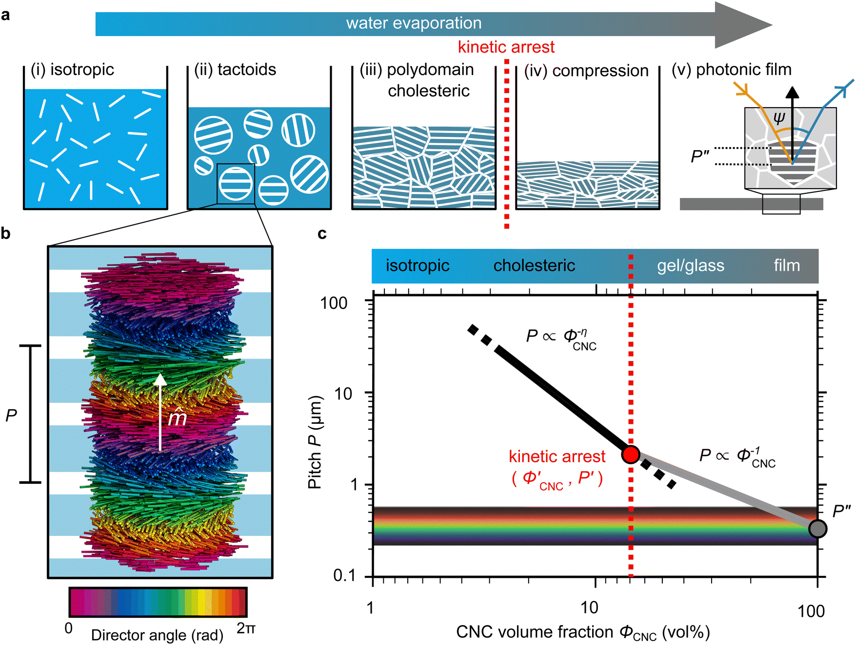 | ||
Fig. 1 (a) Schematic (not to scale) illustrating the evolution of the CNC suspension upon drying, showing (i) the initial isotropic phase, (ii) formation of tactoids leading to (iii) a polydomain cholesteric texture that is fixed by kinetic arrest. (iv) Further geometric compression of the structure results in (v) a helicoidally structured film with structural colour. (b) Rendering of rod-like particles in a left-handed helicoidal structure. The helical axis vector, ![[m with combining circumflex]](https://www.rsc.org/images/entities/i_char_006d_0302.gif) , and pitch, P, are indicated. Rod colour indicates local director angle, while the underlying white stripes represent the P/2 periodicity of the “fingerprint pattern” observable by optical microscopy. (c) Expected pitch evolution with CNC volume fraction for an aligned helicoidal domain, exhibiting two regimes with different power-law exponents, with a transition at the point of kinetic arrest ( , and pitch, P, are indicated. Rod colour indicates local director angle, while the underlying white stripes represent the P/2 periodicity of the “fingerprint pattern” observable by optical microscopy. (c) Expected pitch evolution with CNC volume fraction for an aligned helicoidal domain, exhibiting two regimes with different power-law exponents, with a transition at the point of kinetic arrest (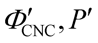 ) and resulting in a final pitch P′′ in the visible regime, as indicated by the rainbow band. ) and resulting in a final pitch P′′ in the visible regime, as indicated by the rainbow band. | ||
Given sufficient time at fixed concentration, a polydomain CNC suspension would evolve towards a monodomain cholesteric with a uniform helical axis and pitch. In a drying suspension, however, the gradually increasing concentration also leads to an increase in viscosity, hindering the equilibration of the system. The suspension eventually undergoes kinetic arrest (KA), in which the CNCs become locked into a non-equilibrium configuration.5,24 As the onset of KA for cholesteric CNC suspensions typically occurs at relatively low volume fraction (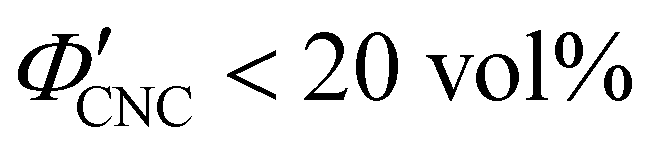 ),19,25,32 substantial further shrinkage of the structure is inevitable as the sample dries into a solid film (
 ). For a kinetically-arrested suspension pinned to a dish, compression occurs primarily in the vertical direction (Fig. 1(a)-(iv)), which leads to a distorted helicoidal structure in the resulting film.28
The expected evolution of the pitch with CNC volume fraction in a drying suspension is illustrated in Fig. 1(c). In a suspension at equilibrium, the cholesteric pitch is typically on the order of 1–100 μm, and its decrease with CNC concentration is typically well-described by a power-law relation of the form P ∼ Φ−ηCNC with exponent η typically in the range [1,2].4 A gradually-dried CNC suspension, such as a dish dried under ambient laboratory conditions, initially evolves slowly enough for the pitch to closely follow this equilibrium behaviour.19 However, KA fixes the relative arrangement of CNCs within the helicoidal structure, which prevents the local alignment of the CNCs from “winding up” to reach their equilibrium pitch value. As such, the further reduction of pitch after KA, (i.e., for  ) is due to geometric compression and distortion of the structure upon drying.19 In dish-cast suspensions, the pitch of vertically-aligned helicoidal domains decreases from the pitch at KA, P′, according to a second power law, P ∼ Φ−1CNC, until the water is fully evaporated (
 ) and the final pitch, P′′, is reached (note that single and double prime symbols are used to denote properties of the system at the onset of KA and in the final film, respectively).
As well-established for molecular cholesteric liquid crystals,33,34 the organisation of CNCs into a periodic left-handed helicoidal structure, combined with the intrinsic birefringence of individual CNCs, leads to selective reflection of left-circularly polarised (LCP) light in a narrow wavelength range.35 As illustrated in Fig. 1(a)-(v), a helicoidal domain of pitch P′′ exhibits peak reflection at a wavelength λmax, which obeys a Bragg-like relation:4
λmax = nP′′![[thin space (1/6-em)]](https://www.rsc.org/images/entities/char_2009.gif) cosψ cosψ | (1) |
2 Theory
2.1 Uniaxial compression of tilted helicoidal domains
As illustrated in Fig. 1(a)-(iii), a cholesteric CNC suspension at the onset of KA can be viewed as an ensemble of distinct helicoidal domains. The structure of each domain specified by its helical axis,′, and cholesteric pitch, P′, where the prime symbol indicates a property at the onset of KA (Fig. 2(a)). While there is expected to be considerable variation in ′ between domains due to the spontaneous selection of a helical axis in the original tactoid, much less variation is expected for P′, as the pitch depends on the (reasonably uniform) CNC concentration and intrinsic elastic constants of the CNC cholesteric phase.
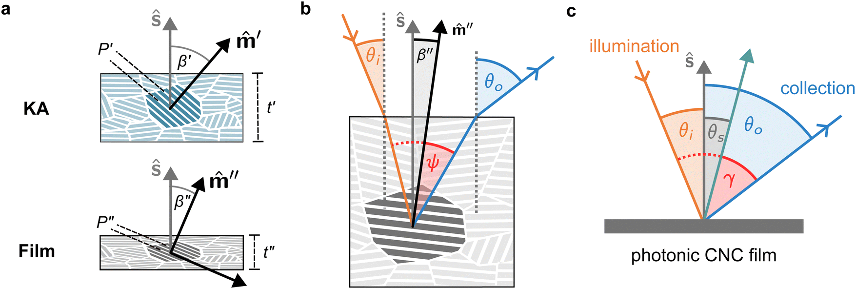 | ||
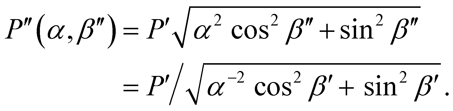
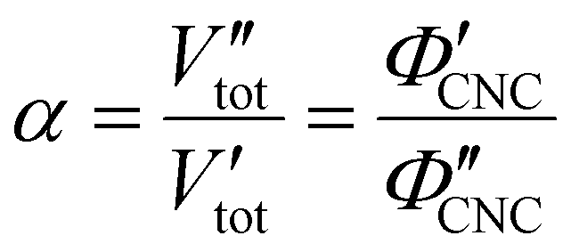
| Fig. 2 (a) Compression of a selected helicoidal domain upon drying. Sample thickness t, helical axis , pitch P and tilt angle β are shown (primed and double-primed symbols denote properties at the onset of KA and in the dry film, respectively). (b) Reflection from a helicoidal domain. Incident light (orange) at an angle θi to the surface normal ŝ (grey) is incident on a tilted domain with helical axis ′′ (black) and tilt angle β′′, with a local angle of incidence ψ (red). The reflected light (blue) exits the film at an outgoing angle θo. (c) Illustration of an AROS measurement for a photonic CNC film. The sample tilt angle θs (grey) is varied while the opening angle γ (red) is kept fixed. The axis midway between the illumination and collection directions (green arrow) is also indicated. In this example, a configuration with 2γ = 45° and θs = +15° is shown. | ||
The drying of a suspension in a horizontal dish from the point of KA into a solid film can be modelled as a uniaxial compression along the vertical direction ẑ (which is identical to the sample normal, ŝ, in this geometry).29 While lateral compression and surface buckling are also possible in other geometries,19,36 the assumption of pure vertical compression is justified when considering the centre of a pinned CNC suspension far from the walls of the dish. This compression reduces the overall sample thickness from its value at KA, t′, to its final dry thickness, t′′, with a compression ratio α = t′′/t′ (Fig. 2(a)). For a helicoidal domain tilted at an angle β′ to the vertical direction at KA (i.e., β′ = cos−1(′·ẑ)), the tilt angle and pitch in the film are given by29
| tanβ′′ = αtanβ′ | (2) |
 | (3) |
As shown in Fig. S2 (ESI†), P′′(α,β′′) describes a unique mapping between tilt angle and pitch after compression.
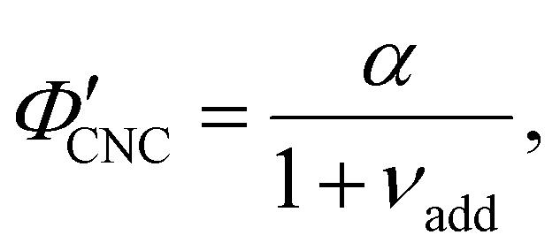
In terms of the total sample volume, Vtot, or the CNC volume fraction, ΦCNC = VCNC/Vtot, the compression ratio is given by
 | (4) |
Aside from the volatile solvent (water), the volumes of other species present in the sample are typically conserved upon drying. It is therefore convenient to express the composition of the sample in terms of the volume ratio of each species i relative to the CNCs:
 | (5) |
The CNC volume fraction can then be written as
| ΦCNC = (1 + νadd + νwat)−1 | (6) |
 is the (conserved) volume ratio for other additives in the suspension. Similarly, the compression ratio can be written as
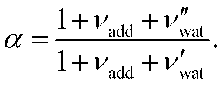 | (7) |
While some water remains in the film after drying in ambient laboratory conditions, its contribution to the sample volume is expected to be negligible: previous studies have reported some limited swelling and porosity in CNC films, with a reasonable bound of  ,
,  for CNC-only films in ambient conditions.4,37 In the following discussion it will therefore be assumed that
  .
.
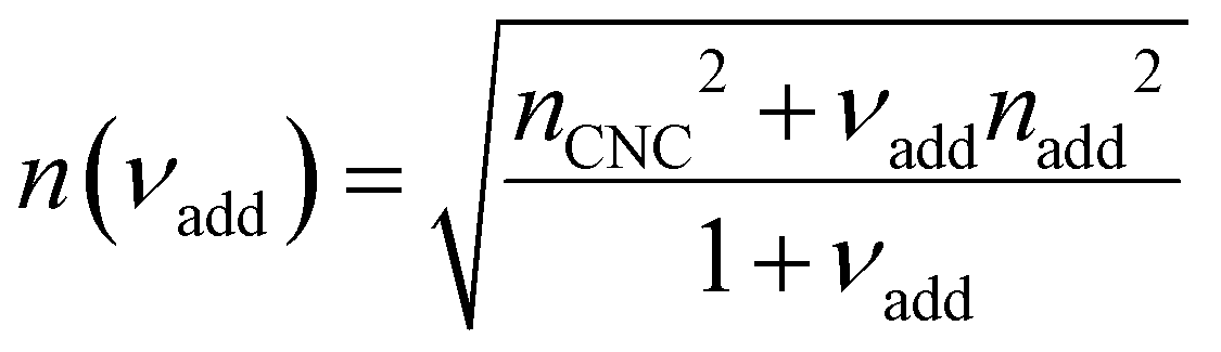
2.2 Angular optical response of polydomain photonic films
The selective reflection from a compressed helicoidal domain is illustrated in Fig. 2(a). For a domain with tilt angle β′′, light incident on the film at an angle θi is refracted at the air-film interface and therefore has a local angle of incidence relative to the domain's helical axis given by38| ψ = sin−1[n−1sin(θi)] + β′′. | (8) |
θo = sin−1[n![[thin space (1/6-em)]](https://www.rsc.org/images/entities/i_char_2009.gif) sin(ψ + β′′)]. sin(ψ + β′′)]. | (9) |
The presence of tilted domains in a photonic CNC film leads to reflection at off-specular angles (since θi ≠ θo for β′′ ≠ 0) and at longer wavelengths (due to the increase in pitch with tilt angle given by eqn (3)).28,29 The red-shifted reflection from tilted helicoidal domains can be quantified by angle-resolved optical spectroscopy (AROS), in which an optical goniometer is used to collect the reflectance spectrum  from the sample for a given combination of illumination and collection angles (θi, θo). Among the possible AROS measurement modes, the reflection from tilted helicoidal domains is most conveniently characterised using a “tilt scan”, in which the sample is rotated with respect to the incident illumination while the relative angle between illumination and collection is kept fixed (Fig. 2(c)).4 In terms of the opening angle between incidence and collection:
 | (10) |
 | (11) |
 | (12) |
 | (13) |
The wavelength of peak reflection, λmax, for a tilted domain is given by combining eqn (1) and (3):
 | (14) |
| λ* = λmax(γ = 0, θs = 0) = nP′′(β′′ = 0) = nαP′, | (15) |
 . Analysis of AROS data therefore provides a method to estimate the experimental conditions at KA (
 ) as the additive content is varied, as recently demonstrated for silica–CNC composite photonic films.30
3 Results and discussion
3.1 Influence of simple ions on the visual appearance of photonic CNC films
One of the most commonly-used methods for controlling the colour of photonic CNC films is to vary the electrolyte concentration in the initial CNC suspension,4,6,39 which is known to decrease the equilibrium pitch.18 However, increasing the ionic strength can also reduce the screening between the negatively-charged CNCs and therefore trigger colloidal gelation, inhibiting cholesteric ordering.20,21 To investigate the influence of ionic strength on CNC self-assembly and KA, CNCs were prepared by sulfuric acid hydrolysis of cotton and subsequent treatments (Experimental Section), followed by extensive dialysis against ultrapure water to remove excess ions. Photonic films were prepared by dish-casting isotropic CNC suspensions with various amounts of additional electrolytes, with the ion content reported as moles of added ions per CNC dry mass, ĉai (Section S1, ESI†).An initial series of photonic films were prepared from 2.0 wt% CNC suspensions with dissolved NaCl in the range ĉNaCl = 0–232 μmol g−1 (Experimental Section). Polarised optical microscopy (POM) images (Fig. 3(a)) show an initial blue-shift in film colour with increasing NaCl:CNC ratio for ĉNaCl < 100 μmol g−1. However, above ĉNaCl ≈ 100 μmol g−1 there is a slight red-shift in apparent film colour and reduction in reflected intensity, and the texture of the POM images becomes finer due to the presence of a larger number of smaller helicoidal domains. All the films reflect left-circularly polarised (LCP) light more strongly than right-circularly polarised (RCP) light, as expected for selective reflection from left-handed helicoidal domains. Micro-spectroscopy (i.e., acquisition of spectra corresponding directly to the region viewed under the microscope) confirmed that the reflection peak evolves by initially blue-shifting for low ĉNaCl values, then broadening with little further blue-shift above ĉNaCl ≈ 100 μmol g−1 (Fig. S4, ESI†). This asymmetric peak broadening can be attributed to the greater contribution of tilted domains to the reflection spectrum, which is captured in the micro-spectra due to the numerical aperture of the objective lens used (NA = 0.2, corresponding to |θi|,|θo| ≤ 11.5°).
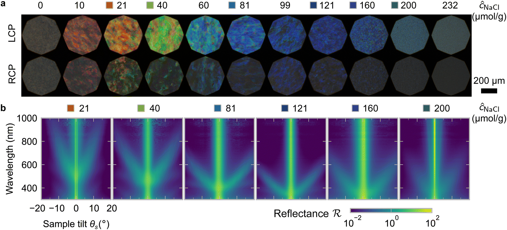 | ||
Fig. 3 (a) Polarised optical microscopy (POM) in reflection mode for photonic CNC films with increasing NaCl:CNC ratio ĉNaCl. Images were acquired through a left- and right-circularly polarised analyser (LCP and RCP respectively). (b) Tilt scan data for selected ĉNaCl values. Colour bar indicates log-scale reflectance  normalised to a diffuse reflectance standard. normalised to a diffuse reflectance standard. | ||
SEM images of the film cross-sections confirm the presence of a Bouligand texture (Fig. S5, ESI†), as expected for the helicoidal structure arising from the cholesteric self-organisation of CNCs. Moreover, the large apparent pitch (P′′ > 1 μm) for the film cast with ĉNaCl = 0 μmol g−1 accounts for the absence of visible colour in Fig. 3(a), as it would correspond to reflection in the infrared wavelength range. More significantly, the SEM images confirm the presence of a polydomain texture with the apparent pitch increasing strongly with domain tilt angle (Fig. S5, ESI†), which validates the interpretation of the AROS data proposed in Section 2.2.
The angular optical response of the photonic films was characterised using AROS, as exemplified for selected samples in Fig. 3(b). Each scan provides a 3D dataset of reflectance versus wavelength and sample tilt angle  , which can be plotted as a log-scale heatmap to allow for a better discrimination of the scattering signal. For all samples, the highest reflectance values are observed near θs = 0° due to specular reflection from the air-film interface and reflection from vertically-aligned domains. In addition, each sample has an off-specular reflection peak that red-shifts with increasing tilt angle (|θs|), leading to a symmetric curve in the plotted heatmap. The peak wavelength at zero tilt, corresponding to reflection from vertically-aligned domains, decreases with increasing ĉNaCl, consistent with the film colour seen in POM images (Fig. 3(a)). However, the width of the curve first increases with ĉNaCl up to around 100 μmol g−1, and then narrows at higher values. The AROS scans also exhibit weaker spectral features, which can be attributed to multi-domain reflection and second-order reflection from distorted helicoidal domains, as illustrated in Fig. S6 (ESI†).
For each film, the peak reflectance versus sample tilt angle, λmax(θs), was fitted using eqn (14) to extract (λ*,P′,α), as shown in Fig. 4. While the λ* values exhibit a continuous decrease with increasing ĉNaCl (Fig. 4(a)), the pitch at KA, P′, only initially decreases until ĉNaCl ≈ 85 μmol g−1, and then increases with a further increase in NaCl:CNC ratio (Fig. 4(b)). Conversely, the compression ratio α peaks around 85 μmol g−1 and then decreases (Fig. 4(c)). This non-monotonic variation in the fitting parameters suggests a division into two regimes, as indicated by the orange and blue shading in Fig. 4.
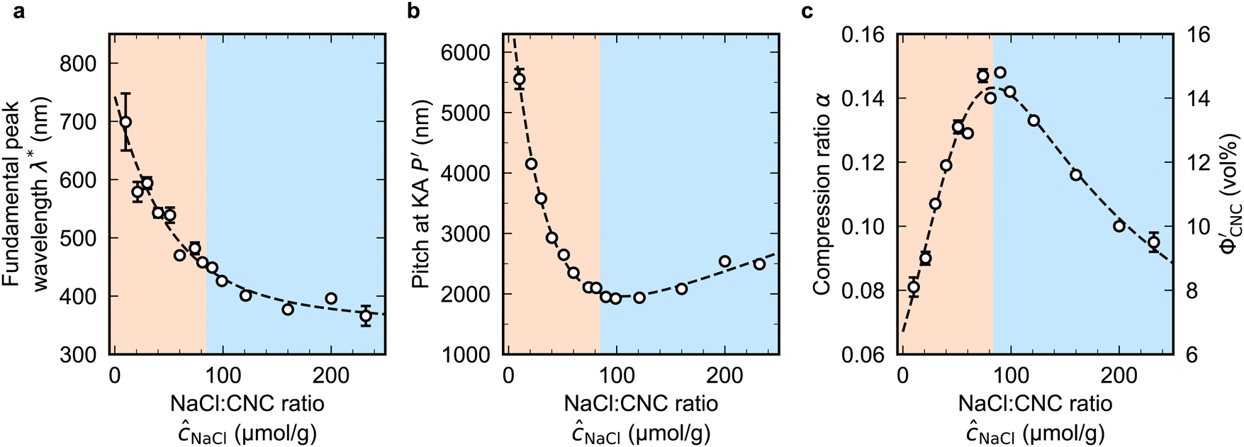 | ||
Fig. 4 Fitting parameters obtained from analysis of AROS data for CNC suspensions with varying ĉNaCl. (a) Fundamental peak wavelength, λ* (b) Pitch at kinetic arrest, P′, (c) compression ratio α, equal to the CNC volume fraction at kinetic arrest,  . Values for ĉNaCl above and below the maximum in α (ĉNaCl ≈ 85 μmol g−1) are indicated by orange and blue shaded regions respectively. Black dashed lines are guides for the eye. . Values for ĉNaCl above and below the maximum in α (ĉNaCl ≈ 85 μmol g−1) are indicated by orange and blue shaded regions respectively. Black dashed lines are guides for the eye. | ||
The compression ratio extracted from the AROS scans can be used to estimate the CNC volume fraction at kinetic arrest, as the Na+ and Cl− ions make a negligible contribution to the total film mass and volume (e.g., for ĉNaCl = 232 μmol g−1, νNaCl = 0.010). In this case, eqn (4) indicates that  , as
, as  . The observed compression ratio therefore provides an estimate of the CNC volume fraction at KA (indicated by the secondary y-axis in Fig. 4(c)), with an initial increase in
  with ĉNaCl (i.e., added ions delay KA), while
  decreases at high ĉNaCl values (i.e., further added ions cause earlier KA). This variation in
  is consistent with the apparent size of helicoidal domains in POM images, when combined with the higher concentration for the onset of the cholesteric phase with increasing electrolyte concentration,18 and is also consistent with the trend in λ*(ĉNaCl) when combined with the blue-shifting effect of added ions on the equilibrium pitch prior to KA, as illustrated in Fig. S10 (ESI†).
3.2 Mechanism of kinetic arrest in CNC suspensions with added electrolyte
The ionic composition of a CNC suspension, both in the terms of overall ionic strength and the valency of the constituent ions, is expected to be a major factor in determining when and how KA occurs. In particular, the loss of colloidal stability for CNCs at high ionic strength is known to induce aggregation, which results in a volume-spanning colloidal gel for suspensions at high enough CNC concentration.26,27 While this mechanism is consistent with the trend in at high ĉNaCl values, it does not explain the delayed KA observed with increasing electrolyte concentration at low ĉNaCl values.
To explore the role of ionic composition, the absolute ion concentrations at KA were estimated from the known ion:CNC ratios and the CNC concentration at KA,  , inferred from the optical analysis (Section S1, ESI†). The absolute Na+ and Cl− concentrations at KA,
 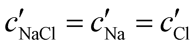 , were simply estimated using the known ĉNaCl value. However, the suspension also contains a substantial amount of H+ ions that originated as counter-ions to the CNC surface charges in the stock suspension. The H:CNC ratio was determined by conductometric titration to be ĉH = 196 μmol g−1 (Fig. S7, ESI†), which allows the H+ concentration at KA,
  , to also be estimated.
The absolute ion concentrations at KA,  and
and  , are plotted versus ĉNaCl in Fig. 5(a). As with the fitting parameters in Fig. 4, two regimes can clearly be seen:
  follows the same non-monotonic trend as α in Fig. 4(c), while
  increases monotonically with ĉNaCl but with a decrease in gradient at the cross-over from the first to the second regime. Notably,
 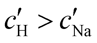 for almost the entire ĉNaCl range, highlighting the importance of considering the counter-ion contribution to the ionic composition of the suspension.
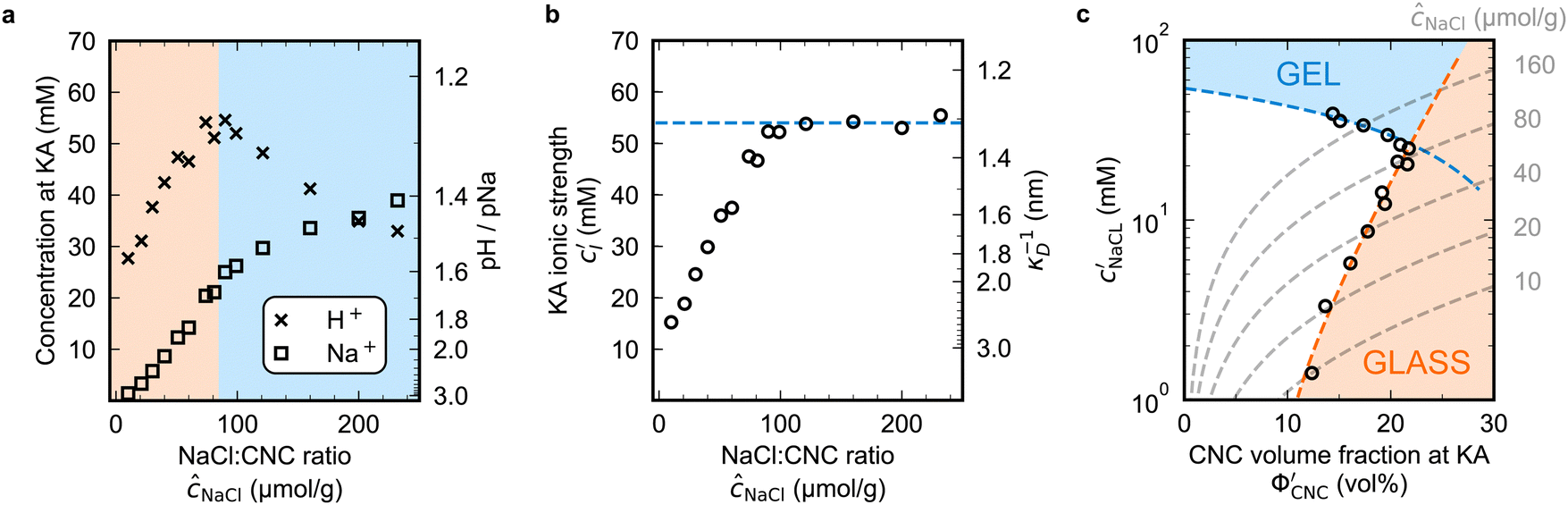 | ||
Fig. 5 Ionic composition for H-CNCs with increasing ĉNaCl: (a)  (crosses) and (crosses) and  (open squares). Secondary axis shows concentrations expressed as pH/pNa. (b) Ionic strength at KA, (open squares). Secondary axis shows concentrations expressed as pH/pNa. (b) Ionic strength at KA,  . Secondary y-axis shows the corresponding Debye length κ−1D. Blue dashed line corresponds to an ionic strength of 54 mM and κ−1D ≈ 1.3 nm. (c) The onset of KA in the ( . Secondary y-axis shows the corresponding Debye length κ−1D. Blue dashed line corresponds to an ionic strength of 54 mM and κ−1D ≈ 1.3 nm. (c) The onset of KA in the ( ) parameter space. Blue dashed line as in (b). Orange dashed line is a guide to the eye. Grey dashed lines indicate the trajectories taken upon drying for CNC suspensions with various ĉNaCl values. ) parameter space. Blue dashed line as in (b). Orange dashed line is a guide to the eye. Grey dashed lines indicate the trajectories taken upon drying for CNC suspensions with various ĉNaCl values. | ||
The optical analysis can also provide insight into the role of pH in the self-assembly of sulfated CNCs. While the pKa value for sulfate half-ester groups on CNCs has not been reliably determined, the value is sometimes stated to be around 2.0 (perhaps due to a comparison with the second pKa value of sulfuric acid).40 As shown by the secondary y-axis in Fig. 5(a), the suspension pH at KA,  , is less than 2.0 for all ĉNaCl values. As such, it is possible that the sulfate half-ester groups are partially protonated at KA, which would reduce their colloidal stability. To elucidate the possible role of pH, the initial CNC suspension with H+ counter-ions (H-CNC) was neutralised using 10 mM NaOH solution to produce a pH 7 suspension with Na+ counter-ions (Na-CNC). Photonic films were then prepared as before by adding various amounts of NaCl solution. The photonic films prepared from Na-CNC and H-CNC were indistinguishable in visual appearance (Fig. S8a, ESI†), while fitting of AROS data for the two series yielded very similar fitting parameters (Fig. S8b–f, ESI†). It can therefore be inferred that varying the suspension pH in the range 1.2–7.0, while keeping the overall ionic strength constant, has no discernible effect on the self-assembly of sulfated CNCs.
The  and
and  values from Fig. 5(a) also be used to estimate the ionic strength of the suspension at KA, which is given for this system by
  , assuming negligible counter-ion condensation on the CNC surface.41 As shown in Fig. 5(b),
  initially increases with ĉNaCl until reaching a plateau above ĉNaCl ≈ 90 μmol g−1. The plateau value of 54 mM for
  compares favourably to other studies of gelation in CNC suspensions, where monovalent electrolytes with concentration in the range 50–200 mM are reported to induce gelation on timescales ∼103 s, comparable to the drying time of the films in this study.21,25,42,43 For cholesteric CNC suspensions in particular, Honorato-Rios et al. reported gelation for CNC suspensions at ionic strength values above approx. 40 mM.25 The ionic strength can also be used to calculate the Debye length at KA, which is given (in nm) by
 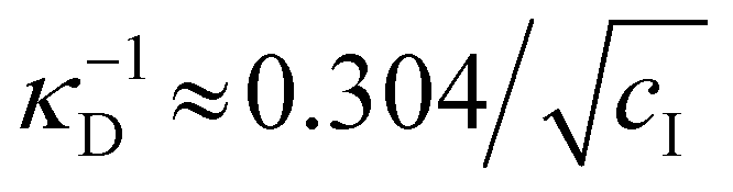 (for water at 20 °C and cI expressed in mol L−1).44 As shown on the secondary y-axis in Fig. 5(b), the Debye length at KA decreases with ĉNaCl before reaching a plateau around 1.3 nm.
The trends in Fig. 4(c) and 5(b) suggest that the KA of CNC suspensions at low ĉNaCl values can be attributed to a low-density colloidal glass transition, in which the CNCs become trapped in a non-equilibrium configuration due to repulsive interactions between neighbouring, non-contacting particles.45 This behaviour is in contrast to colloidal gelation driven by attractive interactions, which only accounts for the behaviour at higher ĉNaCl values. Colloidal glass phases have already been demonstrated in previous rheological studies on CNC suspension at low ionic strength,22 both for isotropic and cholesteric CNC suspensions.26,32 Furthermore, a repulsion-driven KA transition would explain the initial increase in  with increasing ĉNaCl: the CNCs display a larger effective volume fraction than their bare volume due to their electric double layer (which scales with the Debye length), and the glass transition occurs when the effective CNC volume fraction exceeds a critical value. As the Debye length sharply decreases with increasing ĉNaCl, the effective CNC volume fraction also decreases, and so a larger bare CNC volume fraction is needed to reach the required threshold in effective volume fraction. Fig. 5(c) shows the estimated boundary between the liquid crystal and kinetically arrested CNC phases versus CNC concentration and added ion concentration. Increasing ĉNaCl changes the trajectory that a drying CNC suspension takes through this phase space, and therefore determines the point of KA. The phase boundaries postulated here from optical analysis of photonic CNC films are qualitatively similar to those previously obtained by rheological characterisation of Na-CNC suspensions with added NaCl.32
To decouple the roles of ionic strength and ion concentration, photonic CNC films were also prepared from suspensions with added CaCl2 instead of NaCl. For this purpose, an ionic strength:CNC ratio, ĉI, was defined such that ĉI = ĉH/2 + ĉNa for H-CNC films with NaCl, while ĉI = ĉH/2 + 3ĉCa for H-CNC films with CaCl2. POM images for the H-CNC films with added CaCl2 are shown in Fig. S9a, (ESI†), and the corresponding fitting parameters obtained from AROS data are shown in Fig. S9b–d (ESI†). At low ĉI, the data for the two series NaCl and CaCl2 are similar, suggesting that the role of ions in this range is explained solely by the effect of the ionic strength on the Debye length. The similarity between the NaCl and CaCl2 series when expressed in terms of ĉI is also consistent with the hypothesis that KA for low ĉI is a colloidal glass transition. In contrast, at the highest ĉI values, KA occurs slightly earlier in the CaCl2 series, corresponding to a lower ionic strength at KA (Fig. S9e and f, ESI†), which can be attributed to the earlier onset of CNC aggregation and gelation for multivalent ions.43,46,47
3.3 Influence of glucose on the visual appearance of photonic CNC films
Non-volatile additives are often introduced into CNC suspensions to modulate the material properties of the resulting composite films, or to endow them with additional functionality.4 To achieve well-ordered photonic films, the additives must “co-assemble” with the CNCs without disrupting their ability to form a cholesteric mesophase. However, interactions between these additives and CNCs could change both the cholesteric pitch in suspension and the onset of KA, and thereby affect the final pitch. To explore the impact of non-volatile additives on CNC self-assembly, photonic films were prepared with varying amounts of glucose, which was chosen due to its low molecular weight and absence of charged groups (Experimental Section). NaCl was also added at a fixed ratio of ĉNaCl = 100 μmol g−1, a value chosen as being near-optimal for late onset of KA. To determine the glucose:CNC volume ratio νglu, it was assumed that ρglu = 1.5 g cm−3 and ρCNC = 1.6 g cm−3.Optical characterisation of the series of CNC-glucose films is shown in Fig. 6. The POM images show a clear red-shift with increasing νglu, with no discernible change in domain size (Fig. 6(a)). Analysis of AROS data confirms a monotonic increase in λ* with νglu (Fig. 6(b)), with the infrared reflection of the films with the highest glucose loadings explaining the absence of visible structural colouration for those films in Fig. 6(a). However, the pitch at KA is essentially constant (Fig. 6(c)) with P′ = 1968 ± 23 nm across all samples. Similarly, the CNC volume fraction at KA, which is given by combining eqn (6) and (7) to obtain
 | (16) |
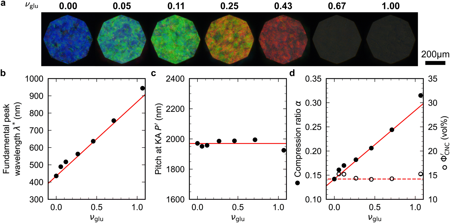 | ||
Fig. 6 (a) POM images (LCP reflection) for photonic CNC films with increasing glucose:CNC volume ratio, νglu. (b)–(d) Fitting parameters (λ*,P′,α) for the CNC-glucose films. In (d) solid circles correspond to α, and open circles correspond to  calculated using eqn (16). Red lines in (b)–(d) show the predicted trends for the reduced compression model (eqn (17) and (18)) with P′ = 1970 nm and calculated using eqn (16). Red lines in (b)–(d) show the predicted trends for the reduced compression model (eqn (17) and (18)) with P′ = 1970 nm and  . . | ||
The trends in λ* and α with νglu for the CNC-glucose films can be modelled by assuming that ( ) are constant, which implies that the red-shift with increasing νglu arises from reduced compression because the non-volatile glucose does not evaporate upon drying. The fitting parameters for this reduced compression model are given by
| α(νadd) = α0(1 + νadd) | (17) |
| λ*(νadd) = n(νadd)α0P′(1 + νadd), | (18) |
 | (19) |
The predictions from the simple reduced compression model (eqn (17) and (18)) for the CNC-glucose films are plotted on Fig. 6(b)–(d). The additive-free fitting parameters (P′ = 1970 nm,  ) were obtained for a film cast alongside the glucose series. To estimate the fundamental peak wavelength it was assumed that nglu = 1.538,48 and nCNC = 1.555.35 The good agreement with the experimental data for CNC-glucose films (Fig. 6(b)–(d)) demonstrates the validity of the reduced compression model. However, glucose is known to be hygroscopic, and it is possible that the assumption
  is no longer valid for large νglu values. The presence of water would correspond to larger α and λ* values (due to a larger effective additive:CNC ratio,
  ), which may explain the deviation at large νglu values.
3.4 Influence of poly(ethylene glycol) on the visual appearance of photonic CNC films
To explore the effect of non-volatile additives beyond small molecules such as glucose (180 Da), CNC films were prepared using 35 kDa poly(ethylene glycol) using the same protocol as for the CNC-glucose films and taking ρPEG = 1.125 g cm−3 (Experimental Section).The CNC-PEG films up to νPEG = 0.36 showed a red-shift comparable to the CNC-glucose films (Fig. 7(a)). However, at higher νPEG values the films exhibited a slight blue-shift in overall film colour, accompanied by a reduction in reflectance and a decrease in the apparent domain size. Upon visual inspection, the films with the highest νPEG values appeared to be phase-separated with structurally-coloured CNC domains interspersed with whitish regions that strongly scatter light across a wide wavelength range. Tilt scans were performed for all CNC-PEG films, but the fitting to the uniaxial compression model (eqn (14)) only gave reliable results for νPEG ≤ 0.61 due to broadband off-specular scattering.
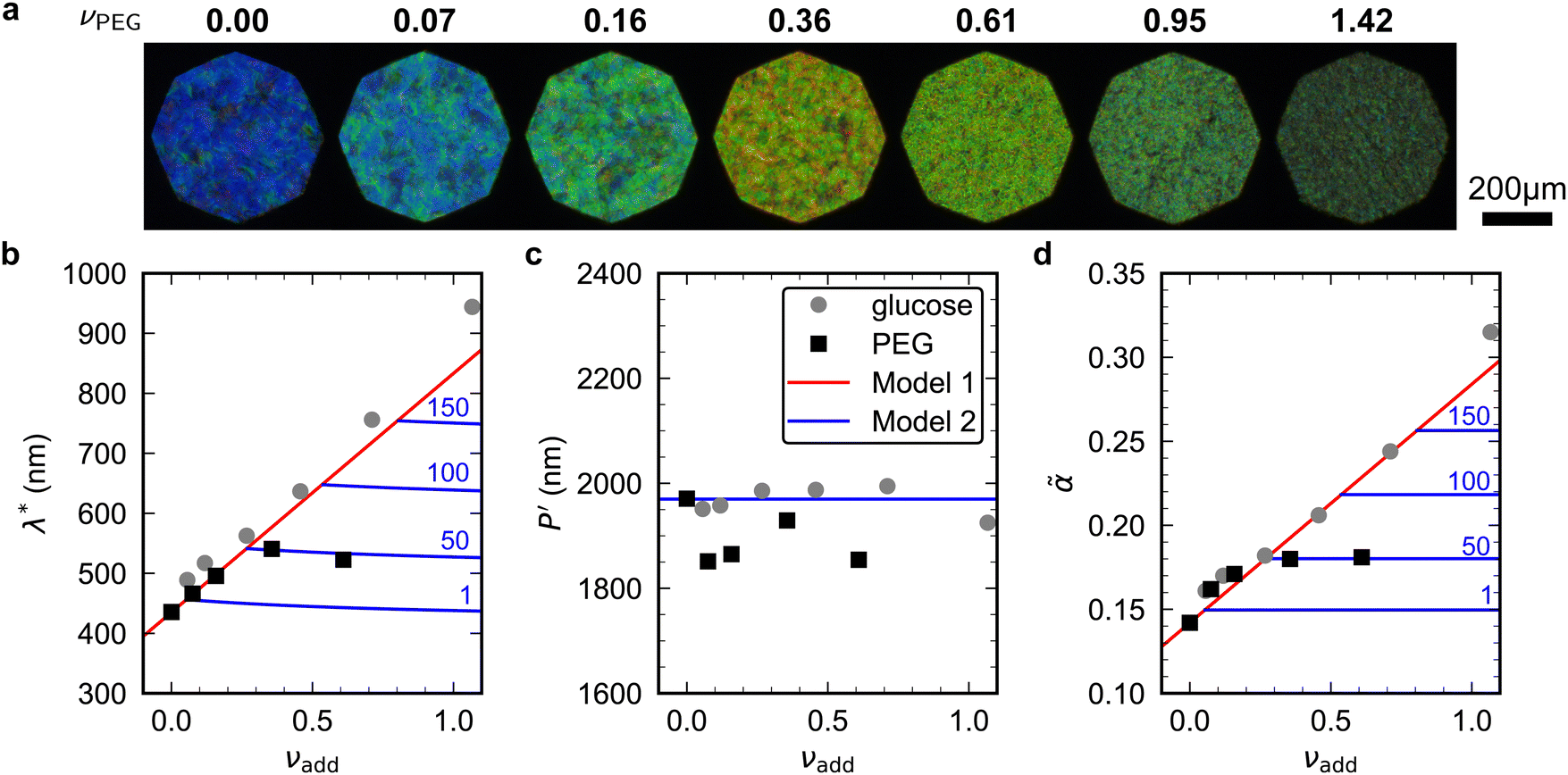 | ||
Fig. 7 (a) POM images (LCP reflection) for photonic CNC films with increasing PEG:CNC volume ratio, νPEG. Note that the additive-free (νPEG = 0) image is identical to νglu = 0 in Fig. 6. (b)–(d) Fitting parameters (λ*,P′,![[small alpha, Greek, tilde]](https://www.rsc.org/images/entities/i_char_e0dc.gif) ) for the CNC-PEG films (black squares), with data for the CNC-glucose films (grey circles) also shown for comparison. Note that in (d) the effective compression ratio is shown instead of α. Red lines in (b)–(d) show the predicted trend for the reduced compression model for PEG (Model 1), while the blue lines show the trend for the modified model (Model 2, ESI,† Section S11), for solubility values of 1, 50, 100 and 150 mg mL−1. ) for the CNC-PEG films (black squares), with data for the CNC-glucose films (grey circles) also shown for comparison. Note that in (d) the effective compression ratio is shown instead of α. Red lines in (b)–(d) show the predicted trend for the reduced compression model for PEG (Model 1), while the blue lines show the trend for the modified model (Model 2, ESI,† Section S11), for solubility values of 1, 50, 100 and 150 mg mL−1. | ||
The fitting parameters are shown in Fig. 7(b)–(d). Similar to the CNC-glucose films, P′ for the CNC-PEG films appears to be independent of νPEG, but a slightly lower mean value than for the CNC-glucose films (P′ = 1894 ± 48 nm, Fig. 7(c)). The plateau in λ* at higher νPEG values (Fig. 7(b)) is therefore matched by a similar plateau in compression ratio (Fig. 7(d)). Consequently, the reduced compression model shows fairly good agreement with the AROS data from the CNC-PEG films for νPEG < 0.3, but fails to describe the trends at higher νPEG values.
The observations of the CNC-PEG films can be explained by the solubility of PEG in aqueous suspension. If the concentration of an additive remains below its solubility until KA, the additive will remain intercalated with the CNCs during compression. This is the case for the CNC-glucose films, as the solubility of glucose (approx. 50 vol% at 20 °C)49 greatly exceeds the highest  value (approx. 16 vol%). In contrast, if the concentration of an additive exceeds its solubility before KA, the additive will begin to precipitate and thus not remain fully intercalated within the CNC cholesteric domains. Such additive precipitation has been reported for CNC films with 20 kDa PEG for νPEG > 0.6, as evidenced by crystalline PEG peaks in X-ray diffraction spectra of the films.16,50 In this study, where a higher molecular weight (35 kDa) was used, crystallisation of PEG is therefore expected at high νPEG values.
To account for the possibility of additive precipitation, a modified compression model was developed with separate terms for additive components that are inside or outside the CNC dispersion, while still assuming that the dispersed additive does not affect the cholesteric pitch or onset of KA (see ESI,† Section S11 for derivation). Crucially, when some of the additive lies outside the CNC dispersion, the effective compression ratio for the CNC phase, denoted , will be less than the compression ratio for the sample as a whole. If the additive reaches its solubility concentration before KA, and partially crystallises out as a separate incompressible solid phase, the volume ratio of dispersed additive versus CNC reaches a saturation value
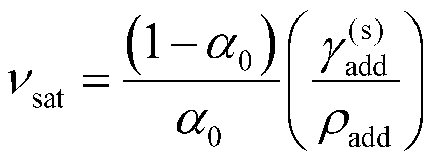 | (20) |
![[small alpha, Greek, tilde]](https://www.rsc.org/images/entities/char_e0dc.gif) sat = α0(1 + νsat) sat = α0(1 + νsat) | (21) |
satP′. For νadd < νsat (when the additive remains fully soluble at KA), = α and the reduced compression model applies.
The modified model was applied to the CNC-PEG films for a range of solubility values. The solubility of 20 kDa PEG is γ(s)PEG = 50 mg mL−1, while for the 35 kDa PEG used in this work no solubility data was available. The predictions of the modified model plotted in Fig. 7(b)–(d) show very good agreement with the trends at νPEG > 0.3 assuming γ(s)PEG = 50 mg mL−1, suggesting that the visual appearance of CNC-PEG films can be explained by the limited solubility of PEG.
Numerous studies on CNC-additive composites have reported red-shifts in film colour with increasing additive:CNC ratio.8–13,15,16 Reduced compression, in general, provides a universal explanation for this trend – the non-volatile additive displaces volatile water, and therefore prevents the suspension from reaching full compression. To compare the findings for glucose and PEG to the existing literature, Fig. S11 (ESI†) shows the peak wavelength of reflection versus additive concentration for a range of neutral additives (glucose, glycerol, dextran, hydroxypropyl cellulose (HPC) and PEG). The reduced compression model is in good agreement with the experimental data for all the additives at various molecular weights, with the notable exception of PEG at high loadings (νPEG ≳ 0.5). A universal model for polymer-CNC films would need to account for depletion-induced phase separation of the suspension into CNC-rich and CNC-poor domains.51–53 In this situation, the heterogeneous local polymer:CNC ratio is expected to lead to varying compression factors, and would explain the multimodal reflectance spectra recently reported for photonic CNC films doped with hydroxypropyl cellulose (HPC).15 While such complex multiphase behaviour is usually undesirable when seeking to produce uniform films, it could perhaps be exploited to create films with a polychromatic optical response.
4 Outlook
The optical analysis used in this work suggests that the onset of KA occurred in the concentration range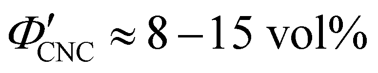 (corresponding to a mass fraction range of
 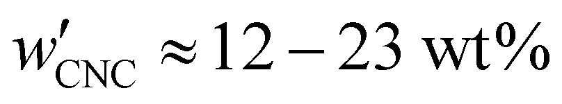 ), which is consistent with a previously reported value for cholesteric suspensions of cotton CNCs.19 However, KA in suspensions of wood pulp CNCs was reported to occur at somewhat lower values (
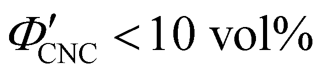 ) based on vial inversion tests and oscillatory rheology.25,32 This disagreement can partially be attributed to differences in intrinsic CNC properties: e.g., for the cotton CNCs used in this work and in ref. 19, the surface charge per mass is 100–200 μmol g−1versus 300–400 μmol g−1 for the wood pulp CNCs used in ref. 25 and 32. Furthermore, values for
  are expected to vary between different techniques, especially as kinetic phenomena are sensitive to the specific experimental procedure (e.g. the elapsed time between initial sample preparation and measurement). Further work is needed to benchmark AROS against more established methods of determining KA in cholesteric CNC suspensions. In situ small angle scattering could also provide valuable insight into the evolution of the suspension microstructure during KA, building upon previous studies of cholesteric CNC suspensions using SANS27,54 and SAXS.55–57
To optimise the visual appearance of photonic CNC films, it is usually desirable to delay KA as long as possible to give the suspension sufficient time to form large, vertically-aligned helicoidal domains (i.e. to maximise the so-called “self-assembly time window”4). This can be achieved by adding simple ions (e.g. NaCl or other monovalent salt), to identify the added ion:CNC ratio at which the KA transition shifts from repulsive-driven to attraction-driven pathway (ĉai ≈ 85 μmol g−1 in this work, with the exact value expected to vary between suspensions). However, to counteract the strong blue-shifting effect of added ions, further modification of the initial suspension is required to achieve the desired film colour. One approach is the inclusion of neutral non-volatile additives, such as glucose or PEG, which have a simply red-shifting effect without affecting domain size at small loadings (νadd < 0.25), but may reduce domain size and impair film appearance at higher loadings and higher molecular weights.
Beyond the neutral non-volatile additives considered in this work, there are numerous other approaches to tune film colour, including: co-assembly with charged macromolecules such as anionic polyacrylate,58 amyloid fibrils59 or silk fibroin;60 modification of CNC morphology using ultrasonication61 or size fractionation;62 modulation of CNC surface charge by desulfation;39 or blending of CNC suspensions from different sources.63 The optical analysis used in this work could be further applied to understand how these approaches affect film appearance. Similarly, while the initial CNC concentration and ambient conditions during drying (e.g. temperature, relative humidity, air flow) were kept fixed in this study, these factors are also expected to affect the domain size and onset of KA. Optimisation of these parameters using AROS should give access to faster drying times while retaining good ordering, which is crucial for commercialisation of CNC-based optical materials.
5 Experimental section
5.1 Production of CNCs
Aqueous CNC suspensions were prepared by sulfuric acid hydrolysis following a previously reported protocol.64 Cotton (60 g of finely shredded Whatman no. 1 cellulose filter paper) was mixed with aqueous sulfuric acid (840 mL, 64 wt%, ≥95% analytical reagent grade, Fisher Scientific) at 64 °C under high mechanical stirring for 30 min. The reaction was then quenched by dilution with ultrapure ice and water (Milli-Q Type 1), and by immersion of the reaction vessel in an ice bath. Soluble cellulose residues and excess acid were then removed by three rounds of centrifugation at 20000g (30, 20, 20 min respectively) with the pellet redispersed in deionized water after each round. Excess ions were then removed by dialysis against ultrapure water using MWCO 12–14 kDa membranes.
After dialysis, the suspension was ultrasonicated by first measuring 40 mL into a 50 mL centrifuge tube and immersing the tube in an ice bath. An ultrasonication tip (Fisherbrand Ultrasonic disintegrator, 20 kHz, tip diameter 12.7 mm) was inserted to a depth of one-third of the sample volume. Sonication was applied at 30% tip amplitude with a 2 second: 1 second ON:OFF cycle and a total ON time of 24 seconds. This treatment corresponds to a sonication dose of 12 J mL−1, using the calibration established in a previous work.65 The sonicated suspensions then underwent vacuum filtration using MF nitrocellulose filter membrane (Sigma Aldrich) in three rounds (with filters of pore size 8.0 μm, 8.0 μm and 0.8 μm respectively).
The CNC mass fraction of the suspension, wCNC = 2.37 wt%, was determined by weighing glass vials of suspension before and after drying for at least 24 hours in a 60 °C oven. The CNC volume fraction (ΦCNC = 1.49 vol%) was calculated by assuming ρCNC = 1.6 g cm−3 and ρw = 1.0 g cm−3 as the density values for CNC and water respectively. The electrolytic conductivity of the suspension was 369 ± 2 μS cm−1, as determined from five measurements at 19 °C using a platinum two-pole conductivity probe (Mettler Toledo InLab 752-6MM, cell constant 1 cm−1). Transmission electron microscopy (TEM) images were used to determine the morphological properties of the CNCs (Fig. S3, ESI†).
5.2 Preparation of CNC suspensions with additives
CNC-additive mixtures were prepared by combining the stock CNC suspension with various additive stock solutions (Table 1) and ultrapure water to achieve the desired composition. All mixtures were weighed using an analytical balance during preparation to obtain the actual composition. The CNC concentration of the mixtures (and samples with no additives) was fixed at 2.0 wt%, unless otherwise stated.| Additive | Description | Supplier | Concentration of prepared stock solution |
|---|---|---|---|
| Sodium chloride (NaCl) | Reagent-grade, powder | Fisher Scientific | 40 mM (2.34 g L−1) |
| Calcium chloride (CaCl2) | Fused granular | Fisher Scientific | 10 mM (1.11 g L−1) |
| Sodium hydroxide (NaOH) | Pellets | Fisher Scientific | 10 mM (0.40 g L−1) |
| D-glucose | Anhydrous | Fisher Scientific | 30 wt% |
| Poly(ethylene glycol) (PEG) | 35 kDa | Sigma Aldrich | 20 wt% |
5.3 Preparation of photonic CNC films
Films were prepared by casting 3.0 mL of each mixture into polystyrene Petri dishes (Corning VWR, 35 mm diameter, non-treated, ref. 430588). The dishes were left to dry under ambient laboratory conditions (20–22 °C, 30–50% RH) for 72 hours in individual custom-made drying chambers, each consisting of a 12 oz kraft paper coffee cup with the bottom removed and the open top covered with a sheet of Whatman filter paper.5.4 Polarised optical microscopy
Polarised optical microscopy (POM) was performed on a Zeiss Axio microscope, with a halogen lamp (Zeiss HAL100) as light source. Images were captured in bright field reflection mode using a 10×/0.2 objective (Nikon T Plan SLWD) and recorded using a CMOS camera (IDS UI-3580LE-C-HQ). The octagonal black border seen in microscopy images arises from partial closure of the field diaphragm.4 The white balance of the images was calibrated using a standard white diffusive reference material (Labsphere USRS-99-010). The polarisation-dependent optical response was determined by analysing (i.e. filtering) the reflected light. For left-circular and right-circular polarized measurements (LCP and RCP respectively), a combination of a superachromatic quarter-wave plate (B. Halle RSU 1.4.15) and linear polariser (Thorlabs WP25M-UB) was used to select either the LCP or RCP component of the reflected light.5.5 Angle-resolved optical spectroscopy (AROS)
Angle-resolved optical spectroscopy was performed using a custom goniometer setup.4 A broadband xenon lamp (Ocean Optics HPX2000) was coupled to a reflective collimator (Thorlabs RC08SMA-F01) via an optical fibre (Avantes FC-UV600-2, core diameter 600 μm) and a plano-convex lens (Thorlabs LA1484-A, f = 300 mm) used to illuminate the sample with a spot diameter ∅ ≈ 1 mm. The reflected light was collected using a second reflective collimator coupled via a second optical fibre (Avantes FC-UV200-2, core diameter 200 μm) to a UV-vis spectrometer (Avantes AvaSpec-HS2048). The recorded light intensity was normalized to a standard white diffusive reference material (LabSphere USRS-99-010) and the exposure time was adjusted automatically using high dynamic range. During each scan, the sample was rotated while the opening angle between illumination and collection was kept fixed.Data availability
All raw datasets relating to this publication are freely accessible at https://doi.org/10.17863/CAM.107626.Conflicts of interest
There are no conflicts to declare.Acknowledgements
The authors acknowledge funding from the EPSRC (T. G. P.: EP/L015978/1, EP/T517847/1; B. F. P., R. M. P., S. V.: EP/W031019/1), Cusanuswerk (S. O.), Hiroshima University (B. F.-P.: WPI-SKCM2), and the Max Planck Society (T. G. P., S. V.).Notes and references
- Y. Habibi, L. A. Lucia and O. J. Rojas, Chem. Rev., 2010, 110, 3479–3500 CrossRef CAS PubMed.
- O. M. Vanderfleet and E. D. Cranston, Nat. Rev. Mater., 2021, 6, 124–144 CrossRef CAS.
- J.-F. Revol, H. Bradford, J. Giasson, R. H. Marchessault and D. G. Gray, Int. J. Biol. Macromol., 1992, 14, 170–172 CrossRef CAS PubMed.
- B. Frka-Petesic, T. G. Parton, C. Honorato-Rios, A. Narkevicius, K. Ballu, Q. Shen, Z. Lu, Y. Ogawa, J. S. Haataja, B. E. Droguet, R. M. Parker and S. Vignolini, Chem. Rev., 2023, 123, 12595–12756 CrossRef CAS PubMed.
- C. Schütz, J. R. Bruckner, C. Honorato-Rios, Z. Tosheva, M. Anyfantakis and J. P. F. Lagerwall, Crystals, 2020, 10, 199 CrossRef.
- J.-F. Revol, J. Godbout and D. G. Gray, J. Pulp Pap. Sci., 1998, 24, 146–149 CAS.
- X. Mu and D. G. Gray, Langmuir, 2014, 30, 9256–9260 CrossRef CAS PubMed.
- Z. Yu, K. Wang and X. Lu, Int. J. Biol. Macromol., 2021, 188, 385–390 CrossRef CAS PubMed.
- Y. Meng, Z. Long, Z. He, X. Fu and C. Dong, Biomacromolecules, 2021, 22, 4479–4488 CrossRef CAS PubMed.
- Y.-D. He, Z.-L. Zhang, J. Xue, X.-H. Wang, F. Song, X.-L. Wang, L.-L. Zhu and Y.-Z. Wang, ACS Appl. Mater. Interfaces, 2018, 10, 5805–5811 CrossRef CAS PubMed.
- M. Xu, W. Li, C. Ma, H. Yu, Y. Wu, Y. Wang, Z. Chen, J. Li and S. Liu, J. Mater. Chem. C, 2018, 6, 5391–5400 RSC.
- X. Dong, D. Li, J.-M. Wu, Z.-L. Zhang, Z.-L. Wang, F. Song, X.-L. Wang and Y.-Z. Wang, ACS Sustainable Chem. Eng., 2022, 10, 10641–10648 CrossRef CAS.
- C. M. Walters, C. E. Boott, T. D. Nguyen, W. Y. Hamad and M. J. Maclachlan, Biomacromolecules, 2020, 21, 1295–1302 CrossRef CAS PubMed.
- D. V. Saraiva, R. Chagas, B. M. de Abreu, C. N. Gouveia, P. E. S. Silva, M. H. Godinho and S. N. Fernandes, Crystals, 2020, 10, 122 CrossRef CAS.
- C. A. Williams, R. M. Parker, A. Kyriacou, M. Murace and S. Vignolini, Adv. Mater., 2023, 36, 2307563 CrossRef PubMed.
- K. Yao, Q. Meng, V. Bulone and Q. Zhou, Adv. Mater., 2017, 29, 1701323 CrossRef PubMed.
- K. W. Klockars, N. E. Yau, B. L. Tardy, J. Majoinen, T. Kämäräinen, K. Miettunen, E. Boutonnet, M. Borghei, J. Beidler and O. J. Rojas, Cellulose, 2019, 26, 491–506 CrossRef CAS.
- X. M. Dong, T. Kimura, J.-F. Revol and D. G. Gray, Langmuir, 1996, 12, 2076–2082 CrossRef CAS.
- R. M. Parker, B. Frka-Petesic, G. Guidetti, G. Kamita, G. Consani, C. Abell and S. Vignolini, ACS Nano, 2016, 10, 8443–8449 CrossRef CAS PubMed.
- K. R. Peddireddy, I. Capron, T. Nicolai and L. Benyahia, Biomacromolecules, 2016, 17, 3298–3304 CrossRef CAS PubMed.
- F. Cherhal, F. Cousin and I. Capron, Langmuir, 2015, 31, 5596–5602 CrossRef CAS PubMed.
- M. Nordenström, A. Fall, G. Nyström and L. Wågberg, Langmuir, 2017, 33, 9772–9780 CrossRef PubMed.
- L. Morlet-Decarnin, T. Divoux and S. Manneville, J. Chem. Phys., 2022, 156, 214901 CrossRef CAS PubMed.
- C. Honorato-Rios, A. Kuhnhold, J. R. Bruckner, R. Dannert, T. Schilling and J. P. F. Lagerwall, Front. Mater., 2016, 3, 21 Search PubMed.
- C. Honorato-Rios, C. Lehr, C. Schutz, R. Sanctuary, M. A. Osipov, J. Baller and J. P. F. Lagerwall, NPG Asia Mater., 2018, 10, 455–465 CrossRef CAS.
- Y. Xu, A. Atrens and J. R. Stokes, Adv. Colloid Interface Sci., 2020, 275, 102076 CrossRef CAS PubMed.
- Y. Xu, E. P. Gilbert, A. Sokolova and J. R. Stokes, J. Colloid Interface Sci., 2024, 658, 660–670 CrossRef CAS PubMed.
- B. Frka-Petesic, G. Guidetti, G. Kamita and S. Vignolini, Adv. Mater., 2017, 29, 1701469 CrossRef PubMed.
- B. Frka-Petesic, G. Kamita, G. Guidetti and S. Vignolini, Phys. Rev. Mater., 2019, 3, 045601 CrossRef CAS PubMed.
- B. Frka-Petesic, J. A. Kelly, G. Jacucci, G. Guidetti, G. Kamita, N. P. Crossette, W. Y. Hamad, M. J. MacLachlan and S. Vignolini, Adv. Mater., 2020, 32, 1906889 CrossRef CAS PubMed.
- P.-X. Wang, W. Y. Hamad and M. J. MacLachlan, Nat. Commun., 2016, 7, 11515 CrossRef PubMed.
- Y. Xu, A. D. Atrens and J. R. Stokes, Soft Matter, 2018, 14, 1953–1963 RSC.
- C. W. Oseen, Trans. Faraday Soc., 1933, 29, 883 RSC.
- H. de Vries, Acta Crystallogr., 1951, 4, 219–226 CrossRef CAS.
- A. G. Dumanli, H. M. van der Kooij, G. Kamita, E. Reisner, J. J. Baumberg, U. Steiner and S. Vignolini, ACS Appl. Mater. Interfaces, 2014, 6, 12302–12306 CrossRef CAS PubMed.
- R. M. Parker, T. H. Zhao, B. Frka-Petesic and S. Vignolini, Nat. Commun., 2022, 13, 3378 CrossRef CAS PubMed.
- T. H. Zhao, R. M. Parker, C. A. Williams, K. T. P. Lim, B. Frka-Petesic and S. Vignolini, Adv. Funct. Mater., 2019, 29, 1804531 CrossRef.
- J. L. Fergason, Mol. Cryst., 1966, 1, 293–307 CrossRef CAS.
- J.-F. Revol, J. Godbout and D. G. Gray, J. Pulp Pap. Sci., 1998, 24(5), 146–149 CAS.
- D. Klemm, F. Kramer, S. Moritz, T. Lindström, M. Ankerfors, D. Gray and A. Dorris, Angew. Chem., Int. Ed., 2011, 50, 5438–5466 CrossRef CAS PubMed.
- S. Lombardo, A. Gençer, C. Schütz, J. Van Rie, S. Eyley and W. Thielemans, Biomacromolecules, 2019, 20, 3181–3190 CrossRef CAS PubMed.
- Y. Boluk, R. Lahiji, L. Zhao and M. T. McDermott, Colloids Surf., A, 2011, 377, 297–303 CrossRef CAS.
- T. Cao and M. Elimelech, J. Colloid Interface Sci., 2021, 584, 456–463 CrossRef CAS PubMed.
- J. N. Israelachvili, Intermolecular and Surface Forces, Academic Press, 2011 Search PubMed.
- E. Zaccarelli, J. Phys.: Condens. Matter, 2007, 19, 323101 CrossRef.
- T. Phan-Xuan, A. Thuresson, M. Skepö, A. Labrador, R. Bordes and A. Matic, Cellulose, 2016, 23, 3653–3663 CrossRef.
- A. Gençer, J. Van Rie, S. Lombardo, K. Kang and W. Thielemans, Biomacromolecules, 2018, 19, 3233–3243 CrossRef PubMed.
- D. Lide, CRC Handbook of Chemistry and Physics, CRC Press, 82nd edn, 2001 Search PubMed.
- L. A. Alves, J. B. Almeida e Silva and M. Giulietti, J. Chem. Eng. Data, 2007, 52, 2166–2170 CrossRef CAS.
- Y. Qi, S. Wang, J. Sun, J. Song, H. Li and J. Guo, Int. J. Biol. Macromol., 2024, 260, 129544 CrossRef CAS PubMed.
- C. D. Edgar and D. G. Gray, Macromolecules, 2002, 35, 7400–7406 CrossRef CAS.
- S. Beck-Candanedo, D. Viet and D. G. Gray, Langmuir, 2006, 22, 8690–8695 CrossRef CAS PubMed.
- L. Bai, S. Huan, B. Zhao, Y. Zhu, J. Esquena, F. Chen, G. Gao, E. Zussman, G. Chu and O. J. Rojas, ACS Nano, 2020, 14, 13380–13390 CrossRef CAS PubMed.
- W. J. Orts, L. Godbout, R. H. Marchessault and J.-F. Revol, Macromolecules, 1998, 31, 5717–5725 CrossRef CAS.
- T. Furuta, E. Yamahara, T. Konishi and N. Ise, Macromolecules, 1996, 29, 8994–8995 CrossRef CAS.
- C. Schutz, M. Agthe, A. B. Fall, K. Gordeyeva, V. Guccini, M. Salajková, T. S. Plivelic, J. P. F. Lagerwall, G. Salazar-Alvarez and L. Bergström, Langmuir, 2015, 31, 6507–6513 CrossRef CAS PubMed.
- F. Pignon, M. Challamel, A. De Geyer, M. Elchamaa, E. F. Semeraro, N. Hengl, B. Jean, J.-L. Putaux, E. Gicquel, J. Bras, S. Prevost, M. Sztucki, T. Narayanan and H. Djeridi, Carbohydr. Polym., 2021, 260, 117751 CrossRef CAS PubMed.
- R. Bardet, N. Belgacem and J. Bras, ACS Appl. Mater. Interfaces, 2015, 7, 4010–4018 CrossRef CAS PubMed.
- K. J. De France, N. Kummer, S. Campioni and G. Nyström, ACS Appl. Mater. Interfaces, 2023, 15, 1958–1968 CrossRef CAS PubMed.
- G. Guidetti, H. Sun, A. Ivanova, B. Marelli and B. Frka-Petesic, Adv. Sustainable Syst., 2021, 5, 2000272 CrossRef CAS.
- S. Beck, J. Bouchard and R. Berry, Biomacromolecules, 2011, 12, 167–172 CrossRef CAS PubMed.
- C. Honorato-Rios and J. P. F. Lagerwall, Commun. Mater., 2020, 1, 69 CrossRef.
- B. Natarajan, A. Krishnamurthy, X. Qin, C. D. Emiroglu, A. Forster, E. J. Foster, C. Weder, D. M. Fox, S. Keten, J. Obrzut and J. W. Gilman, Adv. Funct. Mater., 2018, 28, 1800032 CrossRef.
- X. M. Dong, J.-F. Revol and D. G. Gray, Cellulose, 1998, 5, 19–32 CrossRef CAS.
- T. G. Parton, R. M. Parker, G. T. van de Kerkhof, A. Narkevicius, J. S. Haataja, B. Frka-Petesic and S. Vignolini, Nat. Commun., 2022, 13, 2657 CrossRef CAS PubMed.
Footnote |
| † Electronic supplementary information (ESI) available. See DOI: https://doi.org/10.1039/d4sm00155a |
| This journal is © The Royal Society of Chemistry 2024 |