 Open Access Article
Observing bioorthogonal macrocyclizations in the nuclear envelope of live cells using on/on fluorescence lifetime microscopy†
Sebastian
Pim‡
,
Anaïs C.
Bourgès‡
 ,
Dan
Wu
 ,
Gonzalo
Durán-Sampedro
 ,
Massimiliano
Garre
 and
Donal F.
O'Shea
 *
*
Department of Chemistry, RCSI, Dublin 2, Ireland. E-mail: donalfoshea@rcsi.ie
First published on 20th August 2024
Abstract
The reactive partnership between azides and strained alkynes is at the forefront of bioorthogonal reactions, with their in situ cellular studies often achieved through the use of off to on fluorophores with fluorescence microscopy. In this work, the first demonstration of a bioorthogonal, macrocycle-forming reaction occurring within the nuclear envelope of live cells has been accomplished, utilising on/on fluorescence lifetime imaging microscopy for real-time continuous observation of the transformation. The fluorescent, macrocyclic BF2 azadipyrromethene was accessible through a double 1,3-dipolar cycloaddition within minutes, between a precursor bis-azido substituted fluorophore and Sondheimer diyne in water or organic solvents. Photophysical properties of both the starting bis-azide BF2 azadipyrromethene and the fluorescent macrocyclic products were obtained, with near identical emission wavelengths and intensities, but different lifetimes. In a novel approach, the progress of the live-cell bioorthogonal macrocyclization was successfully tracked through a fluorescence lifetime change of 0.6 ns from starting material to products, with reaction completion achieved within 45 min. The continuous monitoring and imaging of this bioorthogonal transformation in the nuclear membrane and invaginations, of two different cancer cell lines, has been demonstrated using a combination of fluorescence intensity and lifetime imaging with phasor plot analysis. As there is a discernible difference in fluorescence lifetimes between starting material and products, this approach removes the necessity for off-to-on fluorogenic probes when preparing for bioorthogonal cell-imaging and microscopy.
Introduction
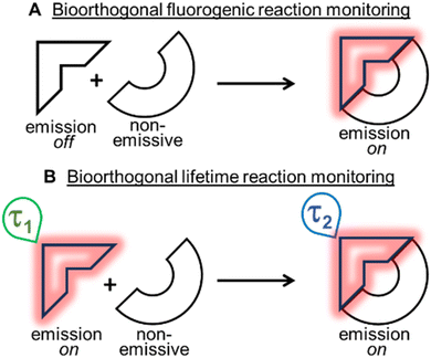
Bioorthogonal transformations are an elite subset of two-reagent reactions that occur with extraordinary selectivity for one another, with high efficiency in biological systems and typically at physiological temperature conditions of 37 °C.1–3 To date, the most successful reaction classes have been the 1,3-dipolar and inverse electron demand Diels–Alder (DA) cycloadditions.4,5 Over the past two decades, the pioneering work of Bertozzi with such reactions has delivered a deeper insight and understanding into chemical biology and the roles of biomolecules within living systems.6–8 Yet, the monitoring of bioorthogonal reactions in living systems can pose a significant challenge, as the conventional analytical techniques of synthetic chemistry are not suitable. The high sensitivity of fluorescence spectroscopy and microscopy have made these the most common analytical approaches adopted to address this issue. Practically, this is achievable by having one of the two bioorthogonal reagents being emissive such that an intensity (fluorogenic) change occurs as a consequence of the reaction (Fig. 1A).9 In this way, confirmation that the reaction has occurred can be achieved through spectroscopic measurements, and the bio-location of the reaction product can be determined through microscopy imaging.Two of the most widely used fluorogenic-responsive bioorthogonal reactions are the azide–alkyne dipolar,10–20 and 1,2,4,5-tetrazine–alkene (or alkyne) DA cycloadditions.21–31 The fluorogenic triggers in these cases being the conversion of azides to triazoles, and tetrazines to pyridazines, causing excited state changes to the fluorophore. Notwithstanding the success of these fluorogenic probes, there exists a bottleneck in their development, as gaining off to on control of excited states, in addition to achieving bioorthogonal reactivity can be both synthetically and photophysically challenging. A further limitation exists in that a fluorogenic approach necessitates the starting reagent be in a non-fluorescent off-state, meaning that no information or data can be gathered until after the reaction has occurred (Fig. 1A). In this work, an alternative approach was explored, utilising an emissive starting material and product, while leveraging changes in fluorescence lifetimes to confirm the occurrence of a bioorthogonal reaction while also monitoring its progress in real-time (Fig. 1B). Conceptually, this relieves the burden of engineering an off to on response, allowing both the starting reagent and product to be strongly emissive, such that data and images could be acquired before, during and after the intracellular reaction. Importantly, this concept could be generally applied to any fluorescent bioorthogonal reaction in which a distinguishable change in lifetime occurs.32
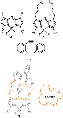
To first develop this bioorthogonal lifetime concept, we used the BF2-azadipyrromethene class of fluorophores as they are a highly robust and emissive platform which are readily synthesised.33 With fluorescence wavelengths in the near-infrared range of 650–850 nm, they are ideally suited for imaging within living systems (Fig. 2, structure A).34,35 The bis-azido substituted fluorophore 1 was selected for this study in anticipation that it would be emissive, with the azide groups electronically disconnected from the fluorophore by a three-carbon methylene chain (Fig. 2). As such, no significant change in emission intensity or wavelengths would be expected upon 1,3-dipolar cycloaddition reaction of the azides. Our complementary bioorthogonal reagent of choice was a strained alkyne, but rather than employing a single alkyne substrate, the Sondheimer diyne 2 was selected, which has been shown to effectively undergo sequential cycloadditions under mild catalyst free conditions.36–48 It was anticipated that upon reaction with 1, the major product would be the 17-membered macrocycle 3 as its ability to form macrocycles with bis-azido dipyrrins has been previously reported (Fig. 2).49
Results and discussion
Synthesis and NMR analysis
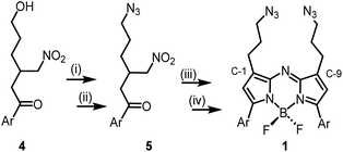
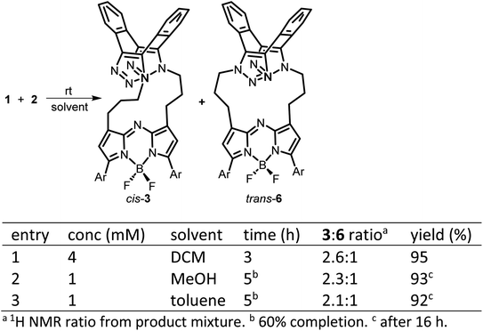
The 1,9-substituted bis-azido functionalized BF2 azadipyrromethene 1 was synthesised via a four-step synthetic route from 6-hydroxy-1-(4-methoxyphenyl)-3-(nitromethyl)hexan-1-one 4, which itself can be generated from readily available starting materials (Scheme 1).50 Reaction of 4 with methanesulfonyl chloride at 0 °C in DCM for 30 min converted the primary alcohol moiety to a mesylate leaving group.49 Without isolation following a solvent exchange, this was treated with sodium azide in DMF for a further 16 h, forming 5 in a high yield of 92%, following purification by silica gel chromatography. Heating of 5 under reflux in MeOH with NH4OAc for 9 h generated an aza-dipyrrin, which upon conversion to its BF2 chelate by stirring in DCM for 3 h with BF3·Et2O and base, gave the targeted fluorophore 1 containing 3-azidopropyl substituents on the C-1 and C-9 β-pyrrole carbons (Scheme 1). Following a subsequent purification by silica gel chromatography, characterization of 1 with 1H, 13C, 19F NMR and high-resolution MS confirmed its structure.With fluorophore 1 in hand, its double 1,3-dipolar cycloadditions with Sondheimer diyne 2 were explored under conventional reaction conditions (Scheme 2). As such, the equimolar reactions of 1 and 2 at concentrations of 4 and 1 mM in dichloromethane (DCM), methanol and toluene were investigated. Encouragingly, it was found that at the higher concentration, the double cycloaddition reaction proceeded most efficiently at rt, reaching completion within 3 h to produce fluorescent macrocycles 3 and its trans isomer 6 in excellent yield (Scheme 2, entry 1). The sequential cycloadditions, which form a dibenzo-cycloocta-bis-1,2,3-triazole capped macrocycle, proved a remarkably efficient transformation with no oligomeric products isolated, negating the need for low concentrations typically required by other cyclization methods. In each solvent, the favoured isomer was cis-3, with it being most predominant in DCM, with a 3/6 ratio of 2.6![[thin space (1/6-em)]](https://www.rsc.org/images/entities/char_2009.gif) :
:![[thin space (1/6-em)]](https://www.rsc.org/images/entities/char_2009.gif) 1 (entries 2 and 3). This isomeric ratio was determined at the second cycloaddition, with the first cycloaddition expected to be the rate determining step. Separation of the minor trans product was achievable using silica gel chromatography, allowing full characterization.
1 (entries 2 and 3). This isomeric ratio was determined at the second cycloaddition, with the first cycloaddition expected to be the rate determining step. Separation of the minor trans product was achievable using silica gel chromatography, allowing full characterization.
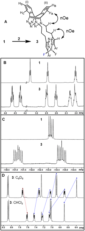
Isomeric cis-3 and trans-6 can be structurally differentiated based on the position at which the methylene linker is N-attached to the triazole rings of the dibenzo-cycloocta-bis-1,2,3-triazole unit. For the major product, cis-3, the methylene substituents originate from adjacent-facing triazole nitrogen atoms, resulting in the two fused benzo substituents of the cap being non-equivalent. This is notable by the four sets of dd peaks, attributable to the two non-equivalent benzo-fused rings of 3 (Fig. 3A). As both rings have separate C–H environments, the COSY spectrum coupling showed δ 7.23 and 7.07 ppm on ring (i), and δ 7.61, 7.46 ppm on ring (ii) (Fig. S1†).
Comparison of 1H NMRs for starting material 1 and cis-3 product was consistent with the formation of a macrocycle, with the methylene protons of the (CH2)3 unit in 3 being diastereotopic (Fig. 3B). Nuclear Overhauser effect spectroscopy (NOESY) showed through-space interactions between the bridging macrocyclic N–CH methylene protons at 4.36 ppm to one of the protons (HA) at 7.07 ppm of the dibenzo-cycloocta-bis-1,2,3-triazole unit, with interactions also seen between the β-pyrrole C–H and its methylene substituent (Fig. 3A double headed arrows, Fig. S1†). An interesting consequence of the macrocyclization conversion of 1 into 3 could be seen by comparison of their19 F NMR spectra. As both fluorine atoms are equivalent in 1, a single peak at δ −133.2 ppm with quartet multiplicity (due to 11B coupling) was recorded, whereas for 3, the spectrum was more complex with two peaks centred at δ −131.3 and −133.7 ppm with double quartet multiplicity due to inequivalent fluorine atoms of the macrocycle, resulting in coupling from both 11B and 19F (Fig. 3C). It was also of interest to investigate the aromatic solvent induced shifts (ASIS) by C6D6 on 3 as an indicator of regions of transient, weak complexation of the macrocycle with the electron-rich benzene ring.51–53 ASIS values were calculated by first recording chemical shifts in CDCl3 and then in a mixture of C6D6/CDCl3 in a 1![[thin space (1/6-em)]](https://www.rsc.org/images/entities/char_2009.gif) :
:![[thin space (1/6-em)]](https://www.rsc.org/images/entities/char_2009.gif) 5 v/v ratio (ASIS = δC6D6 − δCDCl3). It was anticipated that ASIS would occur due to intermolecular electrostatic interactions from the benzene orientating itself around the polar solute-3 dipole (Fig. 3D). This analysis showed that protons at electron rich regions, such as the ortho C–H of the methoxy-aryl ring and the β-pyrrole C–H, had large negative ASIS values of −0.14 and −0.31 ppm, respectively (Table S1†). Interestingly, all four non-equivalent saddle protons had ASIS responses, with three having large negative values (−0.38, −0.19, −0.14) and one positive (+0.12) (Fig. 3D). The largest negative value was from C–HA of the aromatic ring (ii) and the positive value was for C–HD of ring (i) (Fig. 3A and Table S1†).
5 v/v ratio (ASIS = δC6D6 − δCDCl3). It was anticipated that ASIS would occur due to intermolecular electrostatic interactions from the benzene orientating itself around the polar solute-3 dipole (Fig. 3D). This analysis showed that protons at electron rich regions, such as the ortho C–H of the methoxy-aryl ring and the β-pyrrole C–H, had large negative ASIS values of −0.14 and −0.31 ppm, respectively (Table S1†). Interestingly, all four non-equivalent saddle protons had ASIS responses, with three having large negative values (−0.38, −0.19, −0.14) and one positive (+0.12) (Fig. 3D). The largest negative value was from C–HA of the aromatic ring (ii) and the positive value was for C–HD of ring (i) (Fig. 3A and Table S1†).
X-ray structure of 3
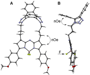
Macrocycle formation was also confirm by X-ray structural analysis of 3. Metallic gold-blue crystals suitable for diffraction were grown by the slow evaporation of a chloroform solution at rt, and found to have crystal system and space group as triclinic and P![[1 with combining macron]](https://www.rsc.org/images/entities/char_0031_0304.gif) , respectively (Table S2†).54 The 17-membered macrocycle was comprised of a saddle-shaped dibenzo-cycloocta-bis-1,2,3-triazole, N-linked through appended three-carbon methylene chains to the C-1/9 β-pyrrole carbons of the fluorophore (Fig. 4A and S2†). Planarity of the central 5-6-5-fused heterocyclic rings of the fluorophore was not affected by the constraining macrocycle, with the largest deviation from this 12-atom plane being 0.1 Å for the N(6) atom (Fig. S2†). Similarly, the 1,2,3-triazole bond lengths and angles were consistent with other triazole rings in non-macrocyclic dibenzo-cycloocta-bis-1,2,3-triazole derivatives.45
, respectively (Table S2†).54 The 17-membered macrocycle was comprised of a saddle-shaped dibenzo-cycloocta-bis-1,2,3-triazole, N-linked through appended three-carbon methylene chains to the C-1/9 β-pyrrole carbons of the fluorophore (Fig. 4A and S2†). Planarity of the central 5-6-5-fused heterocyclic rings of the fluorophore was not affected by the constraining macrocycle, with the largest deviation from this 12-atom plane being 0.1 Å for the N(6) atom (Fig. S2†). Similarly, the 1,2,3-triazole bond lengths and angles were consistent with other triazole rings in non-macrocyclic dibenzo-cycloocta-bis-1,2,3-triazole derivatives.45
Several H to H distances within the X-ray structure of 3 were consistent with the NOESY through-space cross-correlations, such as the averaged aliphatic C–H⋯HA–Ar measured as 2.5 Å, and the C–H⋯H–C–pyrrole measured as 2.65 Å (Fig. 4A and B, double headed arrows). Examination of the difluoro substituents on the tetrahedral boron showed that the F atoms are orientated to either side of the macrocycle. As the macrocycle faces of 3 are non-equivalent, the F atoms are rendered non-equivalent, consistent with the 19F NMR data (Fig. 4B, single headed arrow).
Bioorthogonal reaction conditions
The efficiency of bioorthogonal reactions is influenced by the biological setting in which the transformation takes place. For live cellular work, this would be a heterogeneous, mixed aqueous-lipid solvent system with low reagent concentrations and an upper temperature limit of 37 °C.55 When transitioning from round bottom flask to intracellular reactions, the two most striking differences in conditions are concentration and solvent. While flask conditions would typically employ mM concentration of reagents, this option is not viable for intracellular reactions for which the practically useable upper limit of concentrations is μM. Moreover, the change from a uniform, organic solvent to a heterogeneous, aqueous-lipid environment of a cell must be considered. In order to approximate an aqueous lipid environment for test reactions, solutions of the readily available excipient polysorbate 20 (PS20) in water were utilised (Fig. 5, panel A).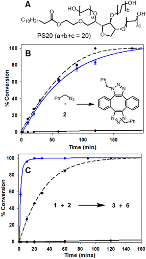 | ||
| Fig. 5 HPLC monitored reactions of Sondheimer diyne 2 with benzyl azide and 1 in MeOH and H2O/PS20 at 37 °C (Fig. S3†). (A) Structure of polysorbate 20. (B) Conversion plot of the reaction of benzyl azide with diyne 2. (C) Conversion plot of the reaction of 1 with diyne 2. Data is an average of three independent experiments. | ||
PS20 is a non-ionic, amphiphilic, polyethylene glycol sorbitan fatty acid ester, with a critical micelle concentration (CMC) of 0.08 mM.56 When dissolved in water, amphiphile PS20 self-assembles into micelles, of which the hydrophilic head interacts with the aqueous phase and the lipophilic core can accumulate water-insoluble reactants due to the hydrophobic effect. For example, the advantage of this solvent system has been exploited by others for the Pd catalysed C–H arylation of aryl carboxylic acids.57 In addition to the macrocyclization, a second previously known reaction of 2 with benzyl azide was also tested (Fig. 5, panel B inset).46,48 In MeOH, at 2 mM concentration and 37 °C, the double cycloaddition of benzyl azide proceeded to completion within 160 min, but when carried out at a low concentration of 5 μM, less than 10% conversion was obtained (Fig. 5, panel B dashed and solid black traces). A similar concentration effect in MeOH was seen for the reaction of 1 and 2, which reached completion at 150 min at 2 mM but, again, had very low conversion at 5 μM (Fig. 5, panel C, dashed and solid black traces). Remarkably, when the reaction of diyne 2 with test substrate benzyl azide or 1 was carried out at 5 μM concentration in aqueous PS20, both reactions were highly effective (Fig. 5, panels B and C, solid blue traces). The benzyl azide reaction reached over 90% completion within 120 min and the bis-azido fluorophore 1 within 15 min, strongly indicating its suitability for intracellular use. This extraordinary rate acceleration could be attributed to the effective reaction volume being reduced, resulting in higher local substrate concentration and giving rise to micellar catalysis.58,59 The reactivity performance observed between 1 and 2 under pseudo-cellular conditions shows the potential for the use of these two reagents in bioorthogonal chemistry.
Photophysical characterisations
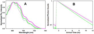
Next, the photophysical characteristics of the emissive starting material and products 1, 3 and 6 were explored. Spectroscopic analyses were performed in both organic (CHCl3, EtOH, toluene) and aqueous media (water/PS20), to allow an overview of the solvent effects on their key parameters. A cross analysis of absorption maxima data for the three dyes showed little difference between them and only very small solvent effects on their λmax. The mean and standard deviations (SD) of absorbance λmax across the different solvents were 1: 660 SD 3 nm; 3: 667.5 SD 1.6 nm; 6: 658.75 SD 5.8 nm. In an analogous fashion, the emission maxima were very similar, with little solvent variance as follows 1: 683.25 SD 2.7 nm; 3: 689.25 SD 1.9 nm and 6: 679 SD 1.9 nm, and each compound having good fluorescence quantum yields (Table 1, Fig. 6 and S4†). An off to on fluorogenic monitoring would clearly not be possible as both starting material and products have very similar absorbance, fluorescence and quantum yield characteristics (Fig. 6).60 However, an examination of the fluorescence lifetime values revealed an alternative opportunity to achieve this goal. A notable increase in lifetime was recorded upon going from starting material to products, with the mean lifetime in three different solvents for 1 as 4.0 (SD 0.37) ns, with 3 and 6 as 4.8 (SD 0.25) and 5.0 (SD 0.35) ns, respectively (Table 1). This difference could be rationalised by the increase constraint imposed by the formation of the macrocycle and is consistent with radiative and non-radiative decay values (Table S3†). Experimentally it was anticipated that the lifetime difference between starting material and products would be sufficient to monitor the reaction progress in real-time.| Entry | Comp. | Solvent | Abs (nm) | Flu (nm) | ϕ flu | τ (ns) |
|---|---|---|---|---|---|---|
| 1 | 1 | CHCl3 | 658 | 683 | 0.25 | 4.5 |
| 2 | 1 | Toluene | 661 | 685 | 0.4 | 4.4 |
| 3 | 1 | EtOH | 657 | 679 | 0.21 | 3.6 |
| 4 | 1 | H2O/PS20 | 665 | 686 | nd | 4.1 |
| 5 | 3 | CHCl3 | 666 | 690 | 0.23 | 5.1 |
| 6 | 3 | Toluene | 670 | 688 | 0.21 | 5.0 |
| 7 | 3 | EtOH | 668 | 687 | 0.17 | 4.5 |
| 8 | 3 | H2O/PS20 | 666 | 692 | nd | 4.7 |
| 9 | 6 | CHCl3 | 657 | 679 | 0.25 | 5.2 |
| 10 | 6 | Toluene | 658 | 678 | 0.24 | 5.0 |
| 11 | 6 | EtOH | 652 | 677 | 0.19 | 4.7 |
| 12 | 6 | H2O/PS20 | 668 | 682 | nd | 4.8 |
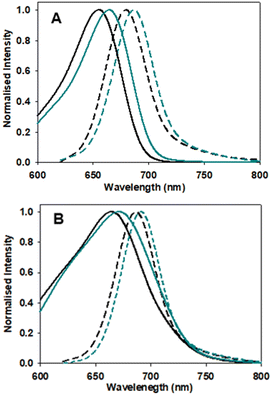 | ||
| Fig. 6 Absorption (solid traces) and emission (dashed traces) spectra of 1 (black) and 3 (blue) in (A) EtOH and (B) H2O/PS20 at 5 μM concentration. | ||
In advance of conducting intracellular experiments, fluorescence lifetime monitoring of the reaction between 1 and 2 was carried out in aqueous PS20. First, the fitted fluorescence lifetime of a solution of 1 (mono-exponential fitted decay) was repeatedly measured every 30 s to establish a starting baseline, then diyne 2 was added with measurements being acquired every 30 s for 45 min. While the lifetime remained unchanged at 3.9 ns prior to the addition of 2, once added it immediately began to increase, reaching a plateau at 4.5 ns by 20 min. To confirm the reaction had reached completion, a second equivalence of 2 was added at 25 min, with no further change in lifetime occurring (Fig. 7, panel A). In addition to the fitted lifetimes, the graphical phasor plot is a powerful method to spatially and temporally represent lifetime data within images.61 Using this approach, the fluorescence lifetime of each pixel within the image is displayed such that pixels with analogous decay curves have comparable positions in the phasor plot (with an average lifetime, τphasor). For this work specifically, the reaction could be monitored in real-time once the starting and finishing lifetimes of the transformation are distinguishable from one another. Fig. 7B shows overlaid phasor plots for the start (Tzero) and end point (T45min) of the reaction between 1 and 2 in H2O/PS20, confirming through the increased phasor lifetimes that the reaction progress can be tracked in this way (for Movie of phasor lifetime changes see Movie S1†).
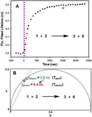 | ||
| Fig. 7 Fluorescence lifetime monitored reaction of 1 with diyne 2 in H2O/PS20 at 10 μM concentration at 37 °C. (A) Plot of fluorescence fitted lifetimes (black circles, mono-exponential fitted decay) versus time as reaction proceeds; pink dashed line indicates time at which 2 was added to the solution of 1; pink star indicates time at which a second equivalent of 2 was added. (B) Overlaid phasor plots showing phase lifetime at Tzero (green circle) and T45min (red circle) see Movie S1† for continual tracking of intermediate time points. | ||
Bioorthogonal reaction of 1 and 2 in live MDA-MB 231 and HeLa Kyoto cells
The nuclear envelope (NE) separates the contents of the nucleus from the cytoplasm, acting as a barrier for the movement of molecules between them and maintaining the nucleus as a distinct biochemical compartment. It has a complex structure, consisting of two concentric inner and outer nuclear membranes (NM), of which the outer is continuous with the endoplasmic reticulum (ER).62 It has underlying nuclear lamina with nuclear pore complexes being the passage way across the membranes. Nuclear invaginations (NI) are another feature of the NE and come about when the nuclear membrane forms tube like channels of varying size criss-crossing the nucleus. The function(s) of these channels remain under active investigation, though they are thought to carry out similar roles to the NE itself which is linked to intranuclear transport, cell signalling and migration.63,64 It has been shown that the existence of NIs transecting the body of the nucleus significantly reduces the distance between nucleoli and the NE which could enable mRNA transport in and out of the nucleus.65 Increased numbers of NIs is associated with several disorders including cancers and neurodegenerative diseases. With regards to cancer, highly differentiated cells are known to have significantly more NIs than non-transformed or mildly differentiated cell lines.66 While much uncertainty remains, a possible explanation for this phenomenon could be that highly proliferative cells need more access to transport of mRNA and proteins, in and out of the nucleus. As such, tools to investigate the NE and NIs are of growing importance and the ability to carry out bioorthogonal reactions within these key cellular regions has not been previously established. Accordingly, the highly aggressive triple-negative metastatic mammary epithelial MDA-MB-231 and the cervical HeLa Kyoto cancer cell lines were chosen for this study.67Initially, it was necessary to establish the subcellular locations, intracellular emission and lifetime characteristics of the pre-synthesised fluorophores 1, 3 and 6. All three were individually incubated with MDA-MB 231 and HeLa Kyoto cells for 90 min, following which live-cell confocal laser scanning microscopy (CLSM) images were acquired. The subcellular localizations were the same for each with the NE, NIs and ER clearly stained (Fig. 8 and S5† for HeLa Kyoto cell images). The localization of 1 to the NM and NI was further confirmed through co-staining experiments with the antibody CF 594 against nuclear lamin B1 in both cell types (Fig. S6†).
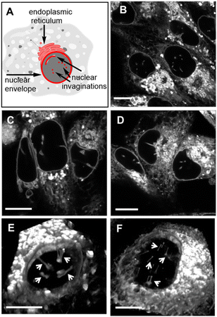 | ||
| Fig. 8 (A) Graphical representation of NE, NI and ER cellular regions of interest. CLSM images of live MDA-MB 231 cells following a 90 min incubation with 0.4 μM concentration of (B) 1, (C) 3 and (D) 6. 3D CLSM images of nuclear topography following incubation with 1 (0.4 μM) in live (E) MDA-MB 231 and (F) HeLa Kyoto cells with NIs indicated by arrows (see Movies S2 and S3† for the 3D nuclear representations of E and F, respectively). Scale bar 10 μm. | ||
Typically, microscopy imaging of the NE and NIs is carried out by immunostaining lamina proteins located on the nuclear body side of the NE through antibody specific bindings.68 Notably, no such recognition exists for the fluorophores of this study, yet effective live-cell labelling was readily achievable. As NIs can transect the nuclear body either horizontally or vertically relative to the imaging focal plane, optical sectioning of cells was carried out to produce a 3D reconstruction of the nucleus. Encouragingly, in MDA-MB 231, and to a lesser extent in HeLa Kyoto cells, numerous NIs could be seen penetrating through the nuclear topography (Fig. 8 panels E, F, Movies S2 and S3†).
Further analysis of the intracellular emission spectra and lifetimes of 1, 3 and 6 in MDA-MB 231 cells confirmed that their photophysical characteristics were comparable to those recorded in solutions (Fig. 9 and S7† for HeLa Kyoto cell data). Importantly, while the emission maxima and intensities were similar for all three fluorophores (λmax 681 nm), the longer lifetimes for the macrocycles (4.8, 4.6 ns) in comparison to the bis-azido fluorophore 1 were measurable and consistent with the values obtained for the solution measurements taken in H2O/PS20 (Fig. 9).
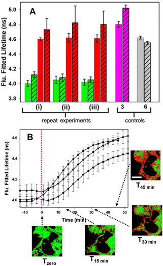
With the intracellular characteristics of the starting bis-azido and product fluorophores understood, the bioorthogonal macrocyclization of 1 and 2 was tested in both cell lines. Experimentally, cells were incubated with 0.4 μM of 1 for 90 min, cell medium was exchanged to remove extracellular 1 and confocal and lifetime images acquired (Tzero) giving a measured exponential lifetime of 4.1 ns (Fig. 10, panels A and B). Cells were then treated with media containing 0.4 μM of diyne 2 and fluorescence lifetime imaging microscopy (FLIM) images recorded every 3 min for 45 min (T45min). Comparison of intensity images at the starting Tzero and 45 min later showed no significant changes, but the fitted lifetimes of entire cells showed that it had increased by 0.6 ns from 4.1 to 4.7 ns (Fig. 10, panels D and E). This change to a longer lifetime, consistent with that of the macrocycles, confirmed that the macrocyclization had occurred throughout all regions of the cell (ER, NM and NI) with the lifetime value in agreement with both solution and intracellular measured values of 3 and 6 (for representative images from repeat experiment see Fig. S8†). Phasor plot representations of the lifetime changes allowed for the progress of the intracellular reactions to be continually observed as they proceeded (Fig. 10, panels C, F, Movies S4 and S5†).69
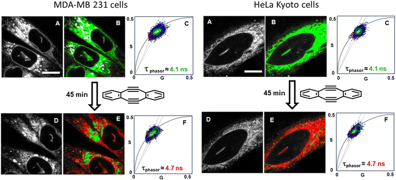 | ||
| Fig. 10 Bioorthogonal macrocyclization of 1 and 2 in MDA-MB 231 (left) and HeLa Kyoto (right) cells. (A) Intensity image at Tzero. (B) FLIM phasor image at Tzero. (C) Expanded region of the phasor plot at Tzero. (D) Intensity image at T45min. (E) FLIM phasor image at T45min. (F) Expanded region of the phasor plot at T45min (see Movies S4 and S5† for phasor plot changes over time). B and E Correspond to the intensity image shown in A and D with pixels coloured depending on their phasor position plot such that pixels inside the green or the red circle in C or F are coloured accordantly in B and E. Same intensity scale for all images of the same region. Bar scale 10 μm. | ||
Control experiment in which cells containing 1 were treated with aqueous PS20 solution without diyne showed no change in lifetimes until subsequently being treated with solutions containing diyne (Fig. S9†). The level of reproducibility was tested through repetition of the experimental process in triplicate with averaged measured lifetime data at Tzero and T45min accumulated from multiple entire cell fields of view (FOV) and specific subcellular regions such as the NIs, as represented in the bar graph in Fig. 11, panel A (see Fig. S10† for HeLa Kyoto data). In all experiments the averaged starting lifetime was 4.1 ± 0.1 ns when measured for both whole cells and individual NIs. Following 45 min incubation with 2, the lifetime values had increased by 0.6 ns for NIs, confirming that the bioorthogonal reaction had in fact occurred within these subcellular regions. The power of combining intensity and lifetime data comes to the fore for continuous dynamic recording of intracellular events. As both the starting and product fluorophores are highly fluorescent, the change in lifetimes can be monitored in real-time as the reaction proceeds. For example, in Fig. 11B the plot of recorded lifetime versus time shows the kinetic profile of the bioorthogonal reaction as it proceeds, which can be directly equated to the time stamped images (for HeLa Kyoto cell plots see Fig. S11†).
In order to confirm that the bioorthogonal driven changes in lifetimes could be detected throughout the NE and NIs, live-cell 3D FLIM experiments at Tzero and T45min were carried out.70 As such, a series of fluorescence lifetime images comprising 20 individual focal planes separated by 0.31 μm was acquired to capture the entire nucleus (Fig. 12, panels A to D and Movie 6†). The measured fitted lifetimes of each optical slice at the two time points are shown in Fig. 12E, confirming that the reaction was uniform throughout both the NE and all NI regions (see Fig. S12† for additional repeat experiment data).
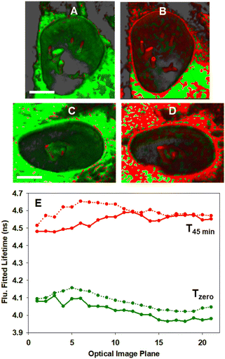 | ||
| Fig. 12 3D Fluorescence lifetime imaging of the NE and NIs in MDA-MB 231 cells. (A and C) Representative FLIM phasor cell images at Tzero. (B and D) Corresponding cell images at T45min. Pixels are coloured as previously described in Fig. 10. (E) Measured fitted lifetimes for each optical slice at Tzero (green trace) and T45min (red trace) for cell A/B (solid line) and for cell C/D (dotted line). See Movie S6† for the 3D FLIM sectioning of the nucleus of A to B and C to D. Scale bar 5 μm. | ||
Conclusion
The use of live-cell FLIM to track the spatial and temporal progress of a bioorthogonal macrocyclization has been presented. Macrocyclization to generate a 17-mer ring was achieved by sequential azide dipolar cycloadditions through the reaction of a bis-azido fluorescent substrate with Sondheimer diyne. The unique, double strained triple bond architecture of the diyne reagent was well suited for this purpose with aqueous solution reactions occurring within minutes at 37 °C. Photophysical measurements showed that both the starting bis-azido fluorophore and product macrocycles had very similar emission maxima and quantum yields and could be readily distinguished from each other by the difference in their fluorescence lifetimes. Confocal microscopy imaging in cancer cell lines showed that both starting and product fluorophores localized to the ER, NE and NIs and that their emission and lifetime characteristics were comparable to those in solution. Treatment of cells with bis-azido substrate 1 and subsequently with equimolar diyne 2 showed a readily observable change in lifetime over 45 min as the macrocyclization took place in each of these subcellular regions. Using both 3D intensity and lifetime imagery it was clearly discernible that the bioorthogonal macrocyclization had occurred in the NE and NIs. It could be anticipated that the use of measured lifetime decays in conjunction with phasor plots could become a powerful analytical method, further pushing the scientific boundaries of bioorthogonal chemistries and delivering new insights at the frontiers of chemical biology. Ongoing synthetic efforts are directed towards generating functionalised diyne derivatives for tracking small molecule entry into the nucleus.Data availability
Details regarding general materials, synthetic methods, analytical spectra, X-ray structure data, cell culture and microscopy methods, control experiments, additional confocal and FLIM images and data are available in the ESI.†Author contributions
DOS: conceptualization, funding acquisition, supervision. SP and DOS: writing original manuscript draft. SP: synthesis and NMR analysis of all compounds, photophysical measurements, bioorthogonal reaction conditions, preparation of figures. AB: cell imaging experiments, image data analysis, lifetime measurements, preparation of figures. GDS, DW: developed the synthetic route to 1. DW: preliminary cell imaging experiments, lifetime measurements. GDS: crystal growth for X-ray structure of 3. MG: imaging data analysis, microscopy training.Conflicts of interest
Authors declare no conflict of interest exist.Acknowledgements
Financial support from Science Foundation Ireland (12/RC/2275) and EU Horizon 2020 Marie-Sklodowska-Curie grant agreement no. 707618. SP acknowledges the RCSI Apjohn fellowship for PhD funding. Images acquired in the RCSI Super Resolution Imaging Consortium funded by Science Foundation Ireland (18/RI/5723). Thanks to Dr Brendan Twamley (Trinity College Dublin) for X-ray analysis and Dr Gary Hessman (Trinity College Dublin) for accurate mass analysis.Notes and references
- M. M. A. Mitry, F. Greco and H. M. I. Osborn, Chemistry, 2023, 29, e202203942 CrossRef CAS PubMed.
- S. L. Scinto, D. A. Bilodeau, R. Hincapie, W. Lee, S. S. Nguyen, M. Xu, C. W. am Ende, M. G. Finn, K. Lang, Q. Lin, J. P. Pezacki, J. A. Prescher, M. S. Robillard and J. M. Fox, Nat. Rev. Methods Primers, 2021, 1, 30 CrossRef CAS PubMed.
- R. E. Bird, S. A. Lemmel, X. Yu and Q. A. Zhou, Bioconjugate Chem., 2021, 32, 2457 CrossRef CAS PubMed.
- S. H. Alamudi, X. Liu and Y.-T. Chang, Biophys. Rev., 2021, 2, 021301 CrossRef PubMed.
- G. Zhao, Z. Li, R. Zhang, L. Zhou, H. Zhao and H. Jiang, Front. Mol. Biosci., 2022, 9, 1055823 CrossRef CAS PubMed.
- N. J. Agard, J. A. Prescher and C. R. Bertozzi, J. Am. Chem. Soc., 2004, 126, 15046 CrossRef CAS PubMed.
- J. M. Baskin, J. A. Prescher, S. T. Laughlin, N. J. Agard, P. V. Chang, I. A. Miller, A. Lo, J. A. Codelli and C. R. Bertozzi, Proc. Natl. Acad. Sci. U.S.A., 2007, 104, 16793 CrossRef CAS PubMed.
- J. C. Jewett, E. M. Sletten and C. R. Bertozzi, J. Am. Chem. Soc., 2010, 132, 3688 CrossRef CAS PubMed.
- Y. Chen, H. Jiang, T. Hao, N. Zhang, M. Li, X. Wang, X. Wang, W. Wei and J. Zhao, Chem. Biomed. Imaging, 2023, 1, 590 CrossRef CAS.
- J. C. Jewett and C. R. Bertozzi, Org. Lett., 2011, 13, 5937 CrossRef CAS PubMed.
- J. Chen, J. Wang, Y. Bai, K. Li, E. S. Garcia, A. L. Ferguson and S. C. Zimmerman, J. Am. Chem. Soc., 2018, 140, 13695 CrossRef CAS PubMed.
- N. A. Moss, G. Seiler, T. F. Leao, G. Castro-Falcon, L. Gerwick, C. C. Hughes and W. H. Gerwick, Angew. Chem., 2019, 58, 9027 CrossRef CAS PubMed.
- P. Shieh, M. J. Hangauer and C. R. Bertozzi, J. Am. Chem. Soc., 2012, 134, 17428 CrossRef CAS PubMed.
- J.-J. Shie, Y.-C. Liu, Y.-M. Lee, C. Lim, J.-M. Fang and C.-H. Wong, J. Am. Chem. Soc., 2014, 136, 9953 CrossRef CAS PubMed.
- P. Shieh, M. Sloan Siegrist, A. J. Cullen and C. R. Bertozzi, Proc. Natl. Acad. Sci. U.S.A., 2014, 111, 5456 CrossRef CAS PubMed.
- O. Demeter, E. A. Fodor, M. Kallay, G. Mezo, K. Nemeth, P. T. Szabo and P. Kele, Chemistry, 2016, 22, 6382 CrossRef CAS PubMed.
- F. Friscourt, C. J. Fahrni and G. J. Boons, J. Am. Chem. Soc., 2012, 134, 18809 CrossRef CAS PubMed.
- J. Zayas, M. Annoual, J. K. Das, Q. Felty, W. G. Gonzalez, J. Miksovska, N. Sharifai, A. Chiba and S. F. Wnuk, Bioconjugate Chem., 2015, 26, 1519 CrossRef CAS PubMed.
- A. Herner, G. Estrada Girona, I. Nikic, M. Kallay, E. A. Lemke and P. Kele, Bioconjugate Chem., 2014, 25, 1370–1374 CrossRef CAS PubMed.
- P. Shieh, V. T. Dien, B. J. Beahm, J. M. Castellano, T. Wyss-Coray and C. R. Bertozzi, J. Am. Chem. Soc., 2015, 137, 7145 CrossRef CAS PubMed.
- M. O. Loehr and N. W. Luedtke, Angew. Chem., 2022, 61, e202112931 CrossRef CAS PubMed.
- X. Liu, M. H. Xiang, W. J. Zhou, F. Wang, X. Chu and J. H. Jiang, Chem. Sci., 2021, 12, 5834 RSC.
- A. Vázquez, R. Dzijak, M. Dračínský, R. Rampmaier, S. J. Siegl and M. Vrabel, Angew. Chem., 2017, 56, 1334 CrossRef PubMed.
- C. Domnick, F. Eggert and S. Kath-Schorr, Chem. Commun., 2015, 51, 8253 RSC.
- T. Plass, S. Milles, C. Koehler, J. Szymański, R. Mueller, M. Wiessler, C. Schultz and E. A. Lemke, Angew. Chem., 2012, 51, 4166 CrossRef CAS PubMed.
- A. Wieczorek, P. Werther, J. Euchner and R. Wombacher, Chem. Sci., 2017, 8, 1506 RSC.
- J. C. Carlson, L. G. Meimetis, S. A. Hilderbrand and R. Weissleder, Angew. Chem., 2013, 52, 6917 CrossRef CAS PubMed.
- H. Wu, J. Yang, J. Seckute and N. K. Devaraj, Angew. Chem., 2014, 53, 5805 CrossRef CAS PubMed.
- C. Caulfield, D. F. O'Shea and D. Wu, Tetrahedron, 2023, 138, 133387 CrossRef CAS.
- L. G. Meimetis, J. C. Carlson, R. J. Giedt, R. H. Kohler and R. Weissleder, Angew. Chem., 2014, 53, 7531 CrossRef CAS PubMed.
- D. Wu and D. F. O'Shea, Chem. Commun., 2017, 53, 10804 RSC.
- R. Datta, T. M. Heaster, J. T. Sharick, A. A. Gillette and M. C. Skala, J. Biomed. Opt., 2020, 25, 071203 CAS.
- Z. Shi, X. Han, W. Hu, H. Bai, B. Peng, L. Ji, Q. Fan, L. Li and W. Huang, Chem. Soc. Rev., 2020, 49, 7533 RSC.
- D. Wu, H. C. Daly, M. Grossi, E. Conroy, B. Li, W. M. Gallagher, R. Elmes and D. F. O'Shea, Chem. Sci., 2019, 10, 6944 RSC.
- D. Wu, S. Cheung, M. Devocelle, L. J. Zhang, Z. L. Chen and D. F. O'Shea, Chem. Commun., 2015, 51, 1666 RSC.
- H. N. C. Wong, P. J. Garratt and F. Sondheimer, J. Am. Chem. Soc., 1974, 96, 5604 CrossRef CAS.
- K. Sharma, A. V. Strizhak, E. Fowler, W. Xu, B. Chappell, H. F. Sore, W. Galloway, M. N. Grayson, Y. H. Lau, L. S. Itzhaki and D. R. Spring, ACS Omega, 2020, 5, 1157 CrossRef CAS PubMed.
- X. Liu, Y. Wu, M. Zhang and K. Zhang, RSC Adv., 2020, 10, 6794 RSC.
- S. Yoshida, J. Tanaka, Y. Nishiyama, Y. Hazama, T. Matsushita and T. Hosoya, Chem. Commun., 2018, 54, 13499 RSC.
- F. Xu, L. Peng, K. Shinohara, T. Morita, S. Yoshida, T. Hosoya, A. Orita and J. Otera, J. Org. Chem., 2014, 79, 11592 CrossRef CAS PubMed.
- M. Tera and N. W. Luedtke, Bioconjugate Chem., 2019, 30, 2991 CrossRef CAS PubMed.
- H. Chen and Q. Miao, ChemPlusChem, 2019, 84, 627 CrossRef CAS PubMed.
- K. Yao, A. Bertran, A. Howarth, J. M. Goicoechea, S. M. Hare, N. H. Rees, M. Foroozandeh, A. M. Bowen and N. J. Farrer, Chem. Commun., 2019, 55, 11287 RSC.
- D. A. Sutton, S. H. Yu, R. Steet and V. V. Popik, Chem. Commun., 2016, 52, 553 RSC.
- S. Yoshida, A. Shiraishi, K. Kanno, T. Matsushita, K. Johmoto, H. Uekusa and T. Hosoya, Sci. Rep., 2011, 1, 82 CrossRef PubMed.
- S. Yoshida, S. Goto, Y. Nishiyama, Y. Hazama, M. Kondo, T. Matsushita and T. Hosoya, Chem. Lett., 2019, 48, 1038 CrossRef CAS.
- D. A. Sutton and V. V. Popik, J. Org. Chem., 2016, 81, 8850 CrossRef CAS PubMed.
- I. Kii, A. Shiraishi, T. Hiramatsu, T. Matsushita, H. Uekusa, S. Yoshida, M. Yamamoto, A. Kudo, M. Hagiwara and T. Hosoya, Org. Biomol. Chem., 2010, 8, 4051 RSC.
- D. Wu, G. Durán-Sampedro, S. Fitzgerald, M. Garre and D. F. O'Shea, Chem. Commun., 2023, 59, 1951 RSC.
- D. Wu, G. Durán-Sampedro and D. F. O'Shea, Front. Chem. Sci. Eng., 2019, 14, 97 CrossRef.
- N. N. Kunio Nikki, Bull. Chem. Soc. Jpn., 1978, 51, 3267 CrossRef.
- L. Chavelas-Hernández, J. R. Valdéz-Camacho, L. G. Hernández-Vázquez, B. E. Dominguez-Mendoza, M. G. Vasquez-Ríos and J. Escalante, Synlett, 2019, 31, 158 Search PubMed.
- N. E. Alexandrou and A. G. Varvoglis, Org. Magn. Reson., 2005, 3, 293 Search PubMed.
- Data deposited as CCDC 2338184.
- V. Šlachtová, M. Chovanec, M. Rahm and M. Vrabel, Top. Curr. Chem., 2024, 382, 2 CrossRef PubMed.
- N. Doshi, R. Fish, K. Padilla and S. Yadav, J. Pharm. Sci., 2020, 109, 2986 CrossRef CAS PubMed.
- Z. Xu, T. Yang, X. Lin, J. D. Elliott and F. Ren, Tetrahedron Lett., 2015, 56, 475 CrossRef CAS.
- F. Fabris, M. Illner, J. U. Repke, A. Scarso and M. Schwarze, Molecules, 2023, 28, 4809 CrossRef CAS PubMed.
- T. Shen, S. Zhou, J. Ruan, X. Chen, X. Liu, X. Ge and C. Qian, Adv. Colloid Interface Sci., 2021, 287, 102299 CrossRef CAS PubMed.
- E. Kozma and P. Kele, Top. Curr. Chem., 2024, 382, 7 CrossRef CAS PubMed.
- B. Torrado, L. Malacrida and S. Ranjit, Sensors, 2022, 22, 999 CrossRef CAS PubMed.
- D. Anand and A. Chaudhuri, J. Membr. Biol., 2023, 256, 137 CrossRef CAS PubMed.
- M. Stiekema, F. Houben, F. Verheyen, M. Borgers, J. Menzel, M. Meschkat, M. van Zandvoort, F. C. S. Ramaekers and J. L. V. Broers, Front. Cell Dev. Biol., 2022, 10, 914286 CrossRef PubMed.
- A. Malhas, C. Goulbourne and D. J. Vaux, Trends Cell Biol., 2011, 21, 362 CrossRef CAS PubMed.
- I. Schoen, L. Aires, J. Ries and V. Vogel, Nucleus, 2017, 8, 506 CrossRef CAS PubMed.
- N. Johnson, M. Krebs, R. Boudreau, G. Giorgi, M. LeGros and C. Larabell, Differentiation, 2003, 71, 414 CrossRef PubMed.
- A. G. Liddane, C. A. McNamara, M. C. Campbell, I. Mercier and J. M. Holaska, Mol. Cancer Res., 2021, 19, 1196 CrossRef CAS PubMed.
- M. Stiekema, F. C. S. Ramaekers, D. Kapsokalyvas, M. A. M. J. van Zandvoort, R. J. A. Veltrop and J. L. V. Broers, Int. J. Mol. Sci., 2021, 22, 10194 CrossRef CAS PubMed.
- M. A. Digman, V. R. Caiolfa, M. Zamai and E. Gratton, Biophys. J., 2008, 94, 14 CrossRef PubMed.
- K. Karrobi, A. Tank, M. Ahsan Fuzail, M. Kalidoss, K. Tilbury, M. Zaman, J. Ferruzzi and D. Roblyer, Sci. Rep., 2023, 13, 3624 CrossRef CAS PubMed.
Footnotes |
| † Electronic supplementary information (ESI) available. CCDC 2338184. For ESI and crystallographic data in CIF or other electronic format see DOI: https://doi.org/10.1039/d4sc03489a |
| ‡ Both authors contributed equally. |
| This journal is © The Royal Society of Chemistry 2024 |

