 Open Access Article
Revealing the effect of conductive carbon materials on the sodium storage performance of sodium iron sulfate†
Wenqing
Zhu‡
 ab,
Zhiqiang
Hao‡
 bc,
Xiaoyan
Shi
b,
Xunzhu
Zhou
bc,
Zhuo
Yang
bc,
Lingling
Zhang
b,
Zongcheng
Miao
*a,
Lin
Li
bc,
Xiaoyan
Shi
b,
Xunzhu
Zhou
bc,
Zhuo
Yang
bc,
Lingling
Zhang
b,
Zongcheng
Miao
*a,
Lin
Li
 *bc and
Shu-Lei
Chou
 *bc
*bc
aSchool of Chemical and Environmental Engineering, Anhui Polytechnic University, Wuhu, Anhui 241000, China. E-mail: miaozongcheng@ahpu.edu.cn
bInstitute for Carbon Neutralization, College of Chemistry and Materials Engineering, Wenzhou University, Wenzhou, Zhejiang 325035, China. E-mail: linli@wzu.edu.cn; chou@wzu.edu.cn
cWenzhou Key Laboratory of Sodium-Ion Batteries, Wenzhou University Technology Innovation Institute for Carbon Neutralization, Wenzhou, Zhejiang 325035, China
First published on 14th February 2024
Abstract
Na2Fe2(SO4)3 (NFS), as a promising cathode for sodium-ion batteries, is still plagued by its poor intrinsic conductivity. In general, hybridization with carbon materials is an effective strategy to improve the sodium storage performance of NFS. However, the role of carbon materials in the electrochemical performance of NFS cathode materials has not been thoroughly investigated. Herein, the effect of carbon materials was revealed by employing various conductive carbon materials as carbon sources. Among these, the NFS coated with Ketjen Black (NFS@KB) shows the largest specific surface area, which is beneficial for electrolyte penetration and rapid ionic/electronic migration, leading to improved electrochemical performance. Therefore, NFS@KB shows a long cycle life (74.6 mA h g−1 after 1000 cycles), superior rate performance (61.5 mA h g−1 at a 5.0 A g−1), and good temperature tolerance (−10 °C to 60 °C). Besides, the practicality of the NFS@KB cathode was further demonstrated by assembling a NFS@KB//hard carbon full cell. Therefore, this research indicates that a suitable carbon material for the NFS cathode can greatly activate the sodium storage performance.
Introduction
Due to energy shortage and environmental pollution, developing renewable clean energy sources (such as solar energy, wind energy, and geothermal energy) has become a hot topic.1–3 The intermittent characteristics of renewable clean energy make large-scale energy storage systems play a key role in its efficient utilization. Electrochemical energy storage technologies with the advantages of high energy conversion efficiency and long cycle life show huge potential for large-scale energy storage systems.4 As a typical electrochemical energy storage technology, lithium-ion batteries (LIBs) are already commercially available in various applications.5 However, the limited and uneven distribution of lithium resources hinders its application in large-scale energy storage systems. Sodium-ion batteries (SIBs) based on an abundant element of Na are regarded as an ideal complement to LIBs.6The relatively large radius of Na+ (r = 1.02 Å) requires high structural stability and a large ion diffusion channel of electrode materials ensures superior electrochemical performance.7 Among the discovered cathode materials, polyanionic compounds have attracted extensive attention due to their robust crystal structures.8–12 Until now, they have been be specifically classified into olivine-type materials,13,14 NASICON materials,15–18 pyrophosphate materials,19–23 and sulfate-based materials.24–28 Iron-based sulfate materials with the merits of low cost and high operation voltage have been considered promising candidates for SIBs. A representative iron-based sulfate, Na2Fe2(SO4)3 (NFS), was first reported as a 3.8 V (vs. Na+/Na) cathode material for SIBs by Yamada's group in 2014,29 and exhibits a high energy density. However, its poor electronic conductivity results in unsatisfactory rate performance. Correspondingly, hybridization with carbon materials has been widely proposed to improve the surface electronic conductivity of NFS.30,31 For example, Chen et al.32 designed a Na2Fe2(SO4)3@C@GO composite, which exhibits excellent rate performance (107.9 mA h g−1 at 12 mA g−1; 75.1 mA h g−1 at 1200 mA g−1). In general, most of the reports focus on boosting sodium storage of NFS; the effect of conductive carbon materials on the electrochemical performance is still a mystery.
Herein, Ketjen Black (KB), Super P, acetylene black, and conductive graphite KS6 were applied to disclose the effect of carbon materials on electrochemical performance. A series of in situ carbon-coated NFS (NFS@C) composites were prepared through a simple solid-phase synthesis method. Among these, NFS@KB shows the best electrochemical performance due to its superior electrochemical reaction kinetics. The NFS@C composite material exhibited excellent cycling performance (a reversible capacity of 74.6 mA h g−1 after 1000 cycles) and rate performance (61.5 mA h g−1 at 5 A g−1). In addition, the NFS@C//HC full cell delivers superior electrochemical performance.
Results and discussion
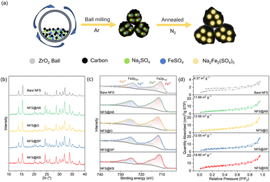
The NFS@C materials were obtained via a low-temperature solid-state reaction method with different conductive carbon materials (Fig. 1a). Based on the type of conductive carbon, these samples were named NFS@KB, NFS@SP, NFS@AB, and NFS@G, respectively. For comparison purposes, a bare NFS material without conductive carbon was also prepared. As shown in Fig. 1b, common impurity phases were not observed in NFS and NFS@C according to X-ray diffraction (XRD). The valence of iron in NFS and NFS@C was investigated by X-ray photoelectron spectroscopy (XPS), and large amounts of Fe2+ and negligible Fe3+ were detected in the NFS@C samples (Fig. 1c). Noticeably, the Fe3+ content in bare NFS is much higher than that in NFS@C samples, suggesting that the introduction of conductive carbon is beneficial for avoiding the oxidation of Fe2+ to Fe3+ during the preparation process. In addition, the characteristic peak (601 cm−1) of the vibrational bonds between Fe2+ and O2− within the isolated FeO6 units was also observed by Fourier transform infrared spectroscopy (FT-IR, Fig. S1, ESI†).32 The peak at 995 cm−1 and 1080 cm−1 was indexed to symmetric stretching and asymmetric vibration of the SO4 units, respectively.Raman spectroscopy was employed to disclose the form of carbon in the NFS@C composites (Fig. S2, ESI†). The intensity ratio (ID/IG) of the D band to the G band of NFS@KB, NFS@SP, NFS@AB, and NFS@G is 1.14, 1.11, 1.6, and 1.28, respectively, indicating that the amorphous carbon in these carbon matrices is dominant.30 The specific surface area of NFS@C materials was analyzed by nitrogen adsorption and desorption. As shown in Fig. 1d, the specific surface area significantly increased in the presence of conductive carbon, which is in favor of electrolyte infiltration enabling an improved electrochemical performance. Noticeably, NFS@KB shows the largest specific surface area of 18.85 m2 g−1. Meanwhile, all of the NFS@C materials show superior thermal stability (>400 °C, Fig. S3, ESI†).
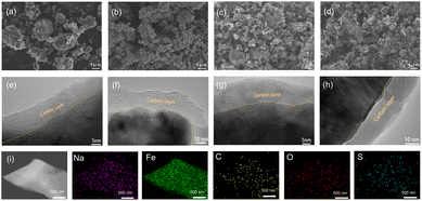
The morphology and microstructure of NFS@C composite materials and bare NFS were investigated by scanning electron microscopy (SEM) and transmission electron microscopy (TEM). As shown in Fig. 2a–d and S4 (ESI†), the particle size of NFS was significantly decreased after introducing conductive carbon. This phenomenon indicated that conductive carbon plays a key role in avoiding agglomeration of NFS, leading to a small particle size. The decreased particle size effectively reduces the Na+ diffusion length ensuring a good electrochemical performance. In addition, the active particles of NFS in the NFS@C composites have been tightly covered by a thin carbon layer (Fig. 2e–h), which can enhance the surface electronic conductivity. As shown in Fig. S5 (ESI†), the HRTEM image also demonstrates that the as-prepared NFS@C composites exhibit good crystallinity. Meanwhile, elemental mapping images reveal that Na, Fe, S, O, and C are uniformly distributed in the obtained NFS@C composite materials (Fig. 2i and S6, ESI†).
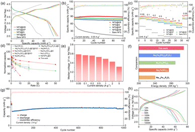
The effect of conductive carbon materials on the electrochemical performance of NFS materials was investigated using half cells. As shown in Fig. 3a, a considerable improvement in the initial discharge capacity was observed when introducing conductive carbon into NFS. All NFS@C composite materials show a smaller overpotential, compared with bare NFS. Among them, NFS@KB exhibits an initial coulombic efficiency of 98.28%, much higher than that of 89.85% in NFS@SP, 92.64% in NFS@AB, and 89.61% in NFS@G, indicating its smallest irreversible capacity loss during the first charge–discharge process. This may be attributed to the construction of a stable cathode–electrolyte interphase on the NFS@KB surface. Meanwhile, the NFS@C composite materials also deliver improved cycling stability and rate performance (Fig. 3b, c, S8 and S9, ESI†). These results indicated that conductive carbon materials can effectively boost the sodium storage performance of NFS, which could be attributed to their good electronic conductivity and the function of inhibiting the agglomeration of NFS. In addition, we also tried to synthesize the sample by adding KB after annealing, denoted as NFS ADD KB. As shown in Fig. S7 (ESI†), KB coating plays a critical role in improving the rate performance and the capacity retention during long-term cycling, where the introduction of KB before annealing (NFS@KB) with a smaller particle size exhibits greatly enhanced electrochemical performance. Remarkably, NFS@KB electrodes show the highest reversible capacity of 85.7 mA h g−1 and the best rate performance (61.5 mA h g−1 at 5.0 A g−1) and cycling stability (specific capacity remains at 87.5 mA h g−1 after 100 cycles). The largest specific area of the NFS@KB composite facilitated Na+ diffusion, which was responsible for the superior electrochemical performance. As shown in Fig. 3d and Table S1,† at a comparative active material loading, the NFS@KB composite material shows a more competitive rate performance than the reported polyanionic cathode material.23,25,32–36 Moreover, NFS@KB electrodes maintain a high discharge voltage in a wide current density range (Fig. 3e). Among the reported iron-based polyanionic materials for SIBs, the NFS@KB composite material shows an acceptable energy density of 311 W h kg−1 (Fig. 3f).16,23,37,38 The long-term cycling stability of the NFS@KB composite was further assessed at 2.0 A g−1, and a high reversible capacity of 74.6 mA h g−1 was maintained even after 1000 cycles (Fig. 3g and h). These results suggest that the NFS@KB composite is a promising cathode candidate for SIBs.
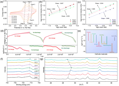
The reason for the superior electrochemical performance of the NFS@KB composite was first investigated by cyclic voltammetry (CV) and galvanostatic intermittent titration (GITT). Representative CV profiles for different sweep rates from 0.1 to 0.5 mV s−1 of the NFS@KB electrode are shown in Fig. 4a. The CV curves show similar shapes with an increase in the scan rate. Meanwhile, Fig. 4b and c show that the b-values of peaks from 1 to 6 of the NFS@KB electrode are determined to be 0.982, 0.857, 0.809, 0.866, 0.934, and 0.985, respectively, demonstrating the dominant pseudocapacitive behavior in the electrochemical process.39 Similarly, the reaction in NFS@SP, NFS@AB, and NFS@G electrodes is also dominated by pseudocapacitive behavior (Fig. S10, ESI†). It is worth noting that the CV curves of bare NFS have no distinct peaks due to the sluggish electrochemical reaction kinetics (Fig. S11, ESI†). Therefore, conductive carbon materials are important to boost the electrochemical reaction activation of NFS.
Subsequently, the Na+ ion diffusion coefficient (DNa+) of NFS@C and bare NFS was estimated by GITT measurement. The voltage (E) is linearly related to  in these samples (Fig. S12, ESI†). Hence, the corresponding Na+ diffusion coefficient can be calculated using the following equation:40
The charge compensation mechanism and structural evolution of the NFS@KB composite during the charge/discharge process were revealed by ex situ XPS and XRD, respectively. Several representative voltage states were selected from the first charge/discharge curve for ex situ XPS testing, including the initial charging stage, points at 4.0 V, 4.25 V, and 4.5 V during the charging process, as well as points at 3.9 V, 3.6 V, and 2.0 V during the discharging process. As shown in Fig. 4f, the Fe 2p peaks move towards a higher binding energy level during the charging process, indicating that Fe2+ has been oxidized to Fe3+. When discharged to 2 V, the peak moves to the initial position, exhibiting a reversible change between Fe2+ and Fe3+. Besides, a highly reversible structure evolution can also be observed by ex situ XRD, suggesting superior structure stability of the NFS@KB composite (Fig. 4g). These characteristics contributed to the outstanding cycling stability of the NFS@KB electrode.
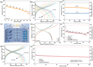
The all-climate performance of NFS@KB was evaluated in a wide temperature range from −10 °C to 60 °C. As shown in Fig. 5a, we measured the electrochemical properties of the NFS@KB material from 60 °C to −10 °C at a current density of 0.5 A g−1. At −10 °C, the cycling specific capacity of 50.4 mA h g−1 is 63.2% of the room-temperature specific capacity, demonstrating that NFS@KB shows excellent performance over a wide temperature range. Noticeably, the polarization of the NFS@KB electrode gradually increases with decreasing temperature (Fig. 5b). Meanwhile, the NFS@KB electrode shows superior cycling stability at −10 °C and 60 °C, with a capacity retention of 98.99% and 90.67% after 100 cycles, respectively (Fig. 5c and S15, ESI†).
To demonstrate the potential of NFS@KB for practical application, a sodium-ion full cell was assembled by using the NFS@KB cathode and a hard carbon (HC) anode (Fig. 5d). The N/P ratio of the full cell is set at approximately 1.1. Before assembling the full cells, the NFS@KB cathode and HC anode are both pre-activated, with NFS@KB//Na half cells cycled at 10 mA g−1 for 3 cycles from 2.0–4.5 V and HC//Na half cells cycled at 10 mA g−1 for 3 cycles from 0.01–2.0 V, respectively. The material characterization and sodium storage performance of HC are displayed in Fig. S16 (ESI†). The NFS@KB//HC full cell delivers a reversible capacity of 71.3 mA h g−1 with a high operation voltage of 3.5 V (Fig. 5e). Furthermore, the NFS@KB//HC full cell also shows a considerable rate performance (Fig. 5f and g). The corresponding specific capacities are as high as 80.0, 74.4, 71.3, 68.2, 65.1, 63.0, and 56.5 mA h g−1 at current densities of 0.01, 0.02, 0.03, 0.05, 0.08, 0.1, and 0.2 A g−1, respectively. Besides, as illustrated in Fig. 5h, the NFS@KB//HC full cell exhibits a superior cycling stability (capacity retention of 77.3% after 100 cycles). These results indicate that NFS@KB is a promising cathode candidate for high-performance SIBs.
Conclusions
In conclusion, various carbon materials were applied to disclose the effect of carbon materials on the electrochemical performance of NFS. Benefiting from the large surface area, NFS@KB shows fast Na+ diffusion kinetics. Meanwhile, NFS@KB exhibits a highly reversible structure evolution and charge compensation mechanism during the charge/discharge process. Therefore, the NFS@KB electrode exhibited the highest reversible capacity 85.7 mA h g−1, the best rate performance (61.5 mA h g−1 at 5.0 A g−1), and superior cycling stability (a reversible capacity of 74.6 mA h g−1 after 1000 cycles). In addition, the NFS@KB electrode delivers good cycling stability at high temperature (90.67% after 100 cycles, 60 °C) and low temperature (98.99% after 100 cycles, −10 °C). The NFS@KB//HC full cells further reveal that NFS@KB is a promising candidate for SIBs. These results provide important insights and proof of the concept that the optimization of carbon materials can significantly boost the sodium-storage performance of NFS-based cathode materials.Data availability
The data that support the findings of this study are available within the article and its ESI,† or from the corresponding author on reasonable request.Author contributions
W. Zhu and Z. Hao contributed equally to this work. Z. Miao, S. Chou and L. Li proposed the idea of this work and designed the experiments. W. Zhu and Z. Hao carried out the preparation and electrochemical measurements. W. Zhu, Z. Hao, and X. Shi performed characterization and data analysis. X. Shi, X. Zhou, and Z. Yang organized the figures. L. Zhang conducted TEM and HAADF tests. Z. Miao, S. Chou, L. Li, X. Zhou and W. Zhu wrote the manuscript. The manuscript was discussed and revised by all authors.Conflicts of interest
There are no conflicts to declare.Acknowledgements
This work was supported by the National Natural Science Foundation of China (22309002, 52202286, 52250710680, and 52171217), the High-end Foreign Experts Recruitment Plan of China (G2023016009L), the Natural Science Foundation of Zhejiang Provincial (LY24B030006), the Key Research and Development Program of Zhejiang Province (2023C011232), the Science and Technology Project of State Grid Corporation of China (5419-202158503A-0-5-ZN), the Basic Research Project of WenZhou City (G20220016), the Science and Technology Plan Project of Wenzhou Municipality (ZG2022032), the Natural Science Foundation of Anhui Province (2108085J11), and the Science Research Foundation of Anhui Polytechnic University (2020YQQ015).Notes and references
- T. Jin, H. X. Li, K. J. Zhu, P.-F. Wang, P. Liu and L. F. Jiao, Chem. Soc. Rev., 2020, 49, 2342–2377 RSC.
- J. Chen, X.-Y. Chen, Y. Liu, Y. Qiao, S.-Y. Guan, L. Li and S.-L. Chou, Energy Environ. Sci., 2023, 16, 792–829 RSC.
- R. Xu, N. Sun, H. Y. Zhou, X. Chang, R. A. Soomro and B. Xu, Battery Energy, 2022, 2, 20220054 CrossRef.
- M. Andwari, A. Pesiridis, S. Rajoo, R. Martinez-Botas and V. Esfahanian, Renewable Sustainable Energy Rev., 2017, 78, 414–430 CrossRef.
- K. Chayambuka, G. Mulder, D. L. Danilov and P. H. L. Notten, Adv. Energy Mater., 2020, 10, 2001310 CrossRef CAS.
- X. Pu, H. Wang, D. Zhao, H. Yang, X. Ai, S. Cao, Z. Chen and Y. Cao, Small, 2019, 15, 1805427 CrossRef PubMed.
- A. Choi, T. Kim, M.-H. Kim, S. W. Lee, Y. H. Jung and H.-W. Lee, Adv. Funct. Mater., 2022, 32, 2111901 CrossRef CAS.
- D. Deb and G. S. Gautam, J. Mater. Res., 2022, 37, 3169–3196 CrossRef CAS.
- T. Or, S. W. D. Gourley, K. Kaliyappan, Y. Zheng, M. Li and Z. Chen, Electrochem. Energy Rev., 2022, 5, 20 CrossRef CAS.
- W. L. Pan, W. Guan and Y. Jiang, Acta Phys.-Chim. Sin., 2020, 36, 1905007 Search PubMed.
- Y. Yuan, Q. Wei, S. Yang, X. Zhang, M. Jia, J. Yuan and X. Yan, Energy Storage Mater., 2022, 50, 760–782 CrossRef.
- W. Yang, Q. Liu, Y. Zhao, D. Mu, G. Tan, H. Gao, L. Li, R. Chen and F. Wu, Small Methods, 2022, 6, 2200555 CrossRef CAS PubMed.
- A. Gutierrez, S. Kim, T. T. Fister and C. S. Johnson, ACS Appl. Mater. Interfaces, 2017, 9, 4391–4396 CrossRef CAS PubMed.
- B. Liu, Q. Zhang, L. Li, L. Zhang, Z. Jin, C. Wang and Z. Su, Chem. Eng. J., 2021, 405, 126689 CrossRef CAS.
- Y. Liu, X. Wu, A. Moeez, Z. Peng, Y. Xia, D. Zhao, J. Liu and W. Li, Adv. Energy Mater., 2022, 13, 2203283 CrossRef.
- R. Rajagopalan, B. Chen, Z. Zhang, X.-L. Wu, Y. Du, Y. Huang, B. Li, Y. Zong, J. Wang, G. H. Nam, M. Sindoro, S. X. Dou, H. K. Liu and H. Zhang, Adv. Mater., 2017, 29, 1605694 CrossRef PubMed.
- M. T. Ahsan, Z. Ali, M. Usman and Y. Hou, Carbon Energy, 2022, 4, 776–819 CrossRef CAS.
- Y. Liu, J. Li, Q. Shen, J. Zhang, P. He, X. Qu and Y. Liu, eScience, 2022, 2, 10–31 CrossRef.
- O. A. Drozhzhin, I. V. Tertov, A. M. Alekseeva, D. A. Aksyonov, K. J. Stevenson, A. M. Abakumov and E. V. Antipov, Chem. Mater., 2019, 31, 7463–7469 CrossRef CAS.
- H. Kim, R. A. Shakoor, C. Park, S. Y. Lim, J.-S. Kim, Y. N. Jo, W. Cho, K. Miyasaka, R. Kahraman, Y. Jung and J. W. Choi, Adv. Funct. Mater., 2013, 23, 1147–1155 CrossRef CAS.
- H. Kim, C. S. Park, J. W. Choi and Y. Jung, Angew. Chem., Int. Ed., 2016, 55, 6662–6666 CrossRef CAS PubMed.
- Y. Chen, C. Dong, L. Chen, C. Fu, Y. Zeng, Q. Wang, Y. Cao and Z. Chen, EcoMat, 2023, e12393 CrossRef CAS.
- J. Gao, Y. Tian, Y. Mei, L. Ni, H. Wang, H. Liu, W. Deng, G. Zou, H. Hou and X. Ji, Chem. Eng. J., 2023, 458, 141385 CrossRef CAS.
- D. Dwibedi, R. Gond, A. Dayamani, R. B. Araujo, S. Chakraborty, R. Ahuja and P. Barpanda, Dalton Trans., 2017, 46, 55–63 RSC.
- B. Awaz and M. O. Ullah, J. Mater. Sci.: Mater. Electron., 2021, 32, 14509–14518 CrossRef.
- A. Nishio, Y. Ishado, K. Nakamoto, E. Kobayashi, A. Inoishi, H. Sakaebe and S. Okada, Mater. Adv., 2022, 3, 6993–7001 RSC.
- A. Plewa, A. Kulka, D. Baster and J. Molenda, Solid State Ionics, 2019, 335, 15–22 CrossRef CAS.
- A. Plewa, A. Kulka, E. Hanc, W. Zajac, J. G. Sun, L. Lu and J. Molenda, J. Mater. Chem. A, 2020, 8, 2728–2740 RSC.
- P. Barpanda, G. Oyama, S. Nishimura, S. C. Chung and A. Yamada, Nat. Commun., 2014, 5, 4358 CrossRef CAS PubMed.
- A. Goñi, A. Iturrondobeitia, I. Gil de Muro, L. Lezama and T. Rojo, J. Power Sources, 2017, 369, 95–102 CrossRef.
- Y. Fang, Q. Liu, X. Feng, W. Chen, X. Ai, L. Wang, L. Wang, Z. Ma, Y. Ren, H. Yang and Y. Cao, J. Energy Chem., 2020, 54, 564–570 CrossRef.
- M. Chen, D. Cortie, Z. Hu, H. Jin, S. Wang, Q. Gu, W. Hua, E. Wang, W. Lai, L. Chen, S.-L. Chou, X.-L. Wang and S.-X. Dou, Adv. Energy Mater., 2018, 8, 1800944 CrossRef.
- S. Kumar, R. Mondal, R. Prakash and P. Singh, Dalton Trans., 2022, 51, 11823–11833 RSC.
- H. Li, X. Chen, T. Jin, W. Bao, Z. Zhang and L. Jiao, Energy Storage Mater., 2018, 16, 383–390 CrossRef.
- S. Li, X. Song, X. Kuai, W. Zhu, K. Tian, X. Li, M. Chen, S. Chou, J. Zhao and L. Gao, J. Mater. Chem. A, 2019, 7, 14656–14669 RSC.
- Y. Liu, N. Zhang, F. Wang, X. Liu, L. Jiao and L.-Z. Fan, Adv. Funct. Mater., 2018, 28, 1801917 CrossRef.
- J. Wang, W. Zeng, J. Zhu, F. Xia, H. Zhao, W. Tian, T. Wang, Y. Zhang, S. Zhang and S. Mu, Nano Energy, 2023, 116, 108822 CrossRef CAS.
- W. Pan, W. Guan, S. Liu, B. Xu, C. Liang, H. Pan, M. Yan and Y. Jiang, J. Mater. Chem. A, 2019, 7, 13197–13204 RSC.
- T. Brezesinski, J. Wang, S. H. Tolbert and B. Dunn, Nat. Mater., 2010, 9, 146–151 CrossRef CAS PubMed.
- W. Weppner and R. A. Huggins, J. Electrochem. Soc., 1977, 124, 1569 CrossRef CAS.
Footnotes |
| † Electronic supplementary information (ESI) available. See DOI: https://doi.org/10.1039/d3sc06956g |
| ‡ These authors contributed equally to this work. |
| This journal is © The Royal Society of Chemistry 2024 |

