
 Open Access Article
 This Open Access Article is licensed under a
 Creative Commons Attribution 3.0 Unported Licence
Machine-learning assisted optimisation during heterogeneous photocatalytic degradation utilising a static mixer under continuous flow†
Thomas M.
Kohl
 ,
Yan
Zuo
,
Benjamin W.
Muir
,
Christian H.
Hornung
,
Anastasios
Polyzos
,
Yutong
Zhu
,
Xingdong
Wang
and
David L. J.
Alexander
*
,
Yan
Zuo
,
Benjamin W.
Muir
,
Christian H.
Hornung
,
Anastasios
Polyzos
,
Yutong
Zhu
,
Xingdong
Wang
and
David L. J.
Alexander
*
CSIRO, Bag 10, Clayton South, Victoria 3169, Australia. E-mail: david.alexander@data61.csiro.au; Tel: +61 3 9545 8038
First published on 5th January 2024
Abstract
A method for process optimisation using Bayesian optimisation (BO) in combination with a continuous flow photoreactor is presented. The photodegradation of an azo dye, as a proof-of-concept model reaction, using a novel TiO2 coated catalytic static mixer (CSM) was optimised using this BO method. The optimal temperature and flow rate were found after conducting 17 experimental runs, with an overall experiment run time of 21 hours. With full automation of the reactor into a closed loop system, this optimisation process can be carried out in under one day with almost no human intervention. Importantly, the algorithm presented successfully accounts for the challenges of catalyst degradation during processing.
1. Introduction
Chemical reaction development and optimisation has changed little over the past century. It continues to rely on human operators to carry out the design, discovery, optimisation, substrate scope and application of new chemical processes. The creative aspects of this process most suited to human exploration are in the discovery and application domains. Reaction optimisation and determination of substrate scope are important albeit repetitive processes that take a great deal of operator time and resources.Recently, machine learning (ML) optimisation routines were introduced to flow chemistry to identify the best reaction conditions in a complex multiparameter space.1–3 In this work, we aimed to develop an autonomous routine, interfacing with a continuous flow reactor platform, to optimise heterogeneous photochemical transformations for any given output parameters. As well as meeting the challenge of efficient simultaneous optimisation of multiple process parameters, our method autonomously adjusted for marked catalyst degradation. This degradation leads to considerably reduced yield over time even when repeating identical process conditions. Human experimenters could modify the experimental configuration to mitigate such degradation (commonly encountered experimentally) to acceptably low levels before commencing optimisation; or they could abandon the catalyst altogether and search for another. Our work avoids this need by automatically finding the optimal product yield for a target photochemical reaction, despite catalyst degradation.
The photocatalytic degradation of the azo dye, reactive orange 16, was selected as a model reaction for process optimisation. Azo dyes are the largest group of colourants, constituting 70% of all organic dyes produced in the world.4 The acute toxicity of azo dyes is low.5 However, the azo linkage may easily be broken down by the enzyme azoreductase found in microorganisms, mammals and humans.6,7 The resulting constituent aromatic amines have a high level of acute and chronic toxicity and carcinogenicity.8,9 Approximately 2–50% of dyes are lost in the effluent during the dyeing process. These are normally discharged into water bodies.10 These coloured discharges are not only aesthetically displeasing; they also pose ecological and public health risks.
Common wastewater treatment processes such as adsorption on activated carbon, flocculation and electrocoagulation are ineffective, costly and often produce secondary wastes.11 Thus there is a need to develop efficient systems leading to complete breakdown of organic pollutants, so that cheaper biological processes can be used as a second stage to achieve complete mineralisation. Photochemical wastewater treatment has been proposed as a potential solution. The combination of a semiconductor such as TiO2-P25 (Degussa), ZnO, Fe2O3, WO3 or CeO2 (among others) with UV light has shown great promise in a research setting.12–18 A challenge exists as photocatalysts are traditionally applied in the form of suspensions or slurries.19,20 Therefore, use of applied heterogeneous photocatalysis remains practically challenging due to the need to separate the TiO2 nanoparticles from the treated wastewater prior to release of the water. This also makes recycling the catalyst impractical and the opaque slurry mixture inhibits efficient use of the available photons.21 These difficulties can be overcome by immobilising TiO2 on support substrates such as beads inside tubes of either glass, Teflon, fiberglass, or woven fibres.22 Additional operating parameters which must also be considered include the type and geometry of photoreactor, the photocatalyst, the optimal use of energy, wavelengths of the radiation and effective irradiation in a scattering and absorbing heterogeneous medium.23
Recent developments in the design of continuous flow photoreactors with immobilised TiO2 on a solid surface have attempted to overcome many of these concerns.24–28 Our approach to the field of continuous flow heterogeneous catalysis has been via the development of specially designed 3D printed catalytic static mixer inserts (CSMs).29 These present a series of improvements including robust and flexible mixer design, superior process control, one step catalyst coating and ease of scalability.30–32 This aspect of flexible mixer design has allowed the traditionally tubular CSMs to be adapted easily for insertion into a commercially available Creaflow HANU-15 flow reactor (Fig. 1).33 Limited examples using a static mixer as a TiO2 support for continuous flow photochemistry have been reported.34–36 Our reactor system has further enhanced temperature control and in-line detection (via UV-vis) capability, in addition to full software control allowing for ML-assisted process optimisation.
 | ||
| Fig. 1 (Top) planar catalytic static mixer design adapted for continuous flow photocatalysis (Australian registered design: 202110400); (centre) coated CSMs containing a catalytically active TiO2 layer and (bottom) modified Creaflow HANU HX-15 photoreactor incorporating the CSM under UV-LED illumination. | ||
One challenge in such reactions is due to unwanted photocatalyst deactivation. Even modest rates of catalyst deactivation can strongly affect the integrity of experimental data, making reaction optimisation difficult or impossible. We demonstrate these challenges using continuous in-line monitoring of the dye decomposition process. The photoinduced deactivation in heterogeneous systems is attributed to irreversible adsorption of by-products, site blocking by carbonaceous residues or foreign particles on the catalyst surface.37 Several strategies to regenerate the photocatalyst have been proposed, including treatment with water vapour, high temperature treatment, oxidation with H2O2 and UV irradiation.25,38 We integrated in situ catalyst regeneration with in-line continuous monitoring of the dye decomposition. We also modified our governing algorithm to estimate the effect of catalyst degradation in the observed data automatically and allow for this effect while optimising the process parameters.
The contributions of this paper are as follows:
1. We evaluate a novel TiO2 coated CSM for continuous photocatalytic degradation of the azo dye, reactive orange 16.
2. We successfully demonstrate a machine learning algorithm for automatic process optimisation of our reactor system.
3. We provide a novel method that deals efficiently with the aforementioned catalyst degradation issue.
2. Experimental
Materials
All reagents and solvents were used without further purification. Reactive orange 16 (dye content >70%) was obtained from Sigma Aldrich, hydrogen peroxide (30%) from Merck and Degussa P25 titanium dioxide powder from Nanoshel.Catalytic static mixer preparation
A 3D printed static mixer was designed to fit within the illuminated window of the Creaflow HANU-15 flow reactor (Australian registered design: 202110400).39 The mixer design has been optimised to maximise light accessible surface area, catalytic surface area and mixing performance. The basic geometry consists of a flat plate with raised, offset crescents on the upper surface to disrupt and direct flow, promoting fluid mixing. The mixer elements were then coated with an industry standard photocatalyst Degussa P25 (TiO2) from a slurry containing hydroxypropyl cellulose (HPC, 0.5 wt%) drying at 120 °C. Final catalyst loadings were 3.0 and 3.3% for the two inserts used in the reactor giving a final reactor volume of 6.24 mL.Reactor configuration
The dye solution was pumped into the modified Creaflow HANU-15 flow reactor using a Knauer Smartline 100 HPLC pump with reactor heating achieved with a Julabo Presto A40 temperature control system. System pressure was monitored using a GEMS 3100 pressure transmitter with back pressure maintained using a Equilibar ZF Series Precision Back Pressure Regulator with Electronic Pilot Controller. The reactor was equipped with a bank of 6 Kessil PR160L LED lights emitting over a narrow range (∼350–420 nm) centred on 370 nm. For safety the LED lights are enclosed in 3 mm thick, clear, Perspex (product VE 003) which absorbs 99.99% of all incident UV light below 400 nm. In-line UV-vis analysis was achieved using a Uniqsis Flow-UV equipped with PFA flow cell. Both the reactor and spectrometer were controlled and monitored via LabVIEW software.UV-vis calibration
A calibration curve was prepared for Reactive Orange 16 over a range of concentrations from 0.1 mg L−1 to 1000 mg L−1. The absorbance peaks at 235 and 315 nm are due to the benzene and naphthalene rings, and the absorbance peak at 480 nm is due to the azo linkage of reactive orange 16. During photodegradation the absorbance at 480 nm is expected to decrease rapidly while the absorbance at 235 nm will remain largely unchanged as the intermediates resulting from the photodegradation of the azo dye still contain the benzene ring. The calibration curves indicate that the dye can be quantified over a range from 10–1000 mg L−1. Plotting the calibration curve over this range gives an excellent linear fit with R2 = 99.85% and ε = 0.00246 for the 495 nm peak (azo linkage).General procedure
A stock solution of reactive orange 16 dye was prepared in deionised (DI) water (100 mg L−1) and passed through the Creaflow HANU-15 flow reactor at 7.47 mL min−1 at a temperature of 67.2 °C (internal) under a pressure of 10 bar and 370 nm UV illumination (Fig. 2). As the dye progressed along the reaction window with a residence time of 49 seconds it was observed to change from bright orange in colour to clear. The product stream was directed through the flow-UV cell with continuous monitoring of the azo linkage wavelength (495 nm). A conversion of 84% (102% s−1) was achieved under these conditions.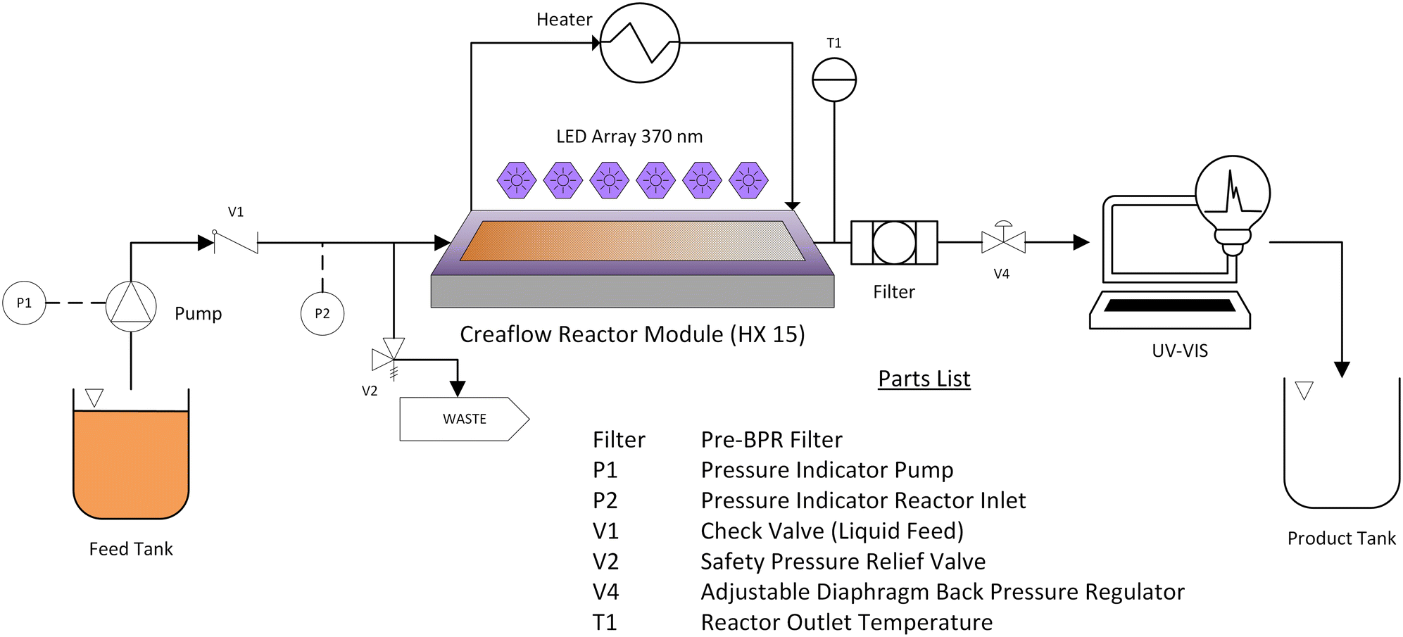 | ||
| Fig. 2 Overview of the flow reactor configuration for continuous azo-dye reduction. The orange dye solution is pumped from the feed tank into the heated Creaflow HX-15 reactor module where it passes over the TiO2 coated catalytic static mixers (CSM) and is exposed to UV light (370 nm). The azo-dye linkage is broken during the reaction giving a colourless product. The remaining dye is quantified by in-line UV-vis after which the products are collected. The reactor system including peripherals and the UV-vis are controlled and monitored via software. | ||
The amount of dye passing over the catalyst since its last regeneration was recorded, and a new regeneration performed whenever this figure reached about 100 mg. Regenerating the catalyst only every 3–5 experiments represents a clear gain in efficiency. Regeneration of the catalyst was achieved by passing 200 mL of 1 M H2O2 over the catalyst (5 mL min−1, 20 °C, 10 bar) with UV illumination at 370 nm. The H2O2 was then washed from the reactor with DI H2O (10 mL min−1, 10 min).
3. Method
Bayesian optimisation
Bayesian optimisation (BO) has emerged as the leading method for global optimisation of systems where only a limited number of data points can be obtained, due to time constraints or cost.40 The power of this method has been demonstrated by comparisons with expert human decision making and other conventional optimization methods.41 It has seen significant success in its application across a wide variety of applications ranging from hyperparameter tuning42 to aerospace design.43,44 In the manufacturing and materials science space, BO has been applied in combination with density functional theory (DFT) in the design of various alloys to improve their performance.45,46 Similarly, BO has been used for high-quality nano-fibre design where the requirements of fibre length and diameter were met within a handful of optimisation iterations, which greatly sped up the production process.47 Most recently, BO has been used to great effect in design of experiments for materials discovery.41,48–51Here, we consider the problem of optimising an objective such as material yield obtained through a chemical reaction. The input conditions for the experiment (e.g. process variables such as temperature and pressure) are summarised in a vector x.
The optimisation is performed through a series of T experiments on x1, x2… xT. To achieve this, BO uses a function f as a surrogate model of the relationship between reaction input conditions and the objective. Typically, f is assumed to be a smooth function; commonly a Gaussian process (GP) is used (other options such as random forests could also be used).42,52 The GP models an underlying probability distribution over possible functions f and represents this distribution using a learned mean and covariance function. Under this setting, an estimate for f can be sampled from the GP.
The surrogate model is successively updated by running new experiments. At a given optimisation iteration t, an acquisition function at(x) is constructed. The next input configuration is chosen among all possible values such that:

Choice of acquisition function
We use expected improvement (EI) as our choice of acquisition function.53 At a given iteration t, the improvement function is given as:| It(x) = max{0, f(x) − yt+} |
 where μt(x) and σt2(x) are the predictive mean and variance of f after t iterations. The closed form of the EI acquisition function can be obtained by taking the expectation over the improvement function I:
αEIt(x) = ![[Doublestruck E]](https://www.rsc.org/images/entities/i_char_e168.gif) [It(x)] = σt(x)ϕ(γ) + (μt(x) − yt+)Φ(γ) [It(x)] = σt(x)ϕ(γ) + (μt(x) − yt+)Φ(γ) |
System overview
The initial parameter configuration for the photoreactor may be chosen at random within a predetermined range for each parameter input. Our experimental setup incorporates two parameters to be optimised: the set flow rate, which ranges from 0.1 to 10 mL per minute and the set reactor temperature, which ranges from 20 to 80 °C. These values are output to a parameter file used as an input to the Reactor Control Software, coded in LabVIEW. This sets the flow rates for the pumps, temperature, pressure, and light intensity to be used in the photoreactor. The remaining dye after each experiment is measured in a UV-vis spectrometer, also controlled using LabVIEW software. The output data file from this software is then processed to consolidate results down to a single measure of yield output for the experiment, in this case the total conversion as a percentage of initial dye concentration. Conversion per minute of residence time was chosen as the response variable to be maximised by a Bayesian optimisation (BO) algorithm. This gives a measure of system throughput and overall efficiency, balancing the tendency of longer residence times to give higher conversion with the need to process reagents at an efficient rate. The next parameter configuration to be used is chosen using a BO algorithm based on the accumulation of collected data. The flow of data in the experimental setup is depicted in Fig. 3.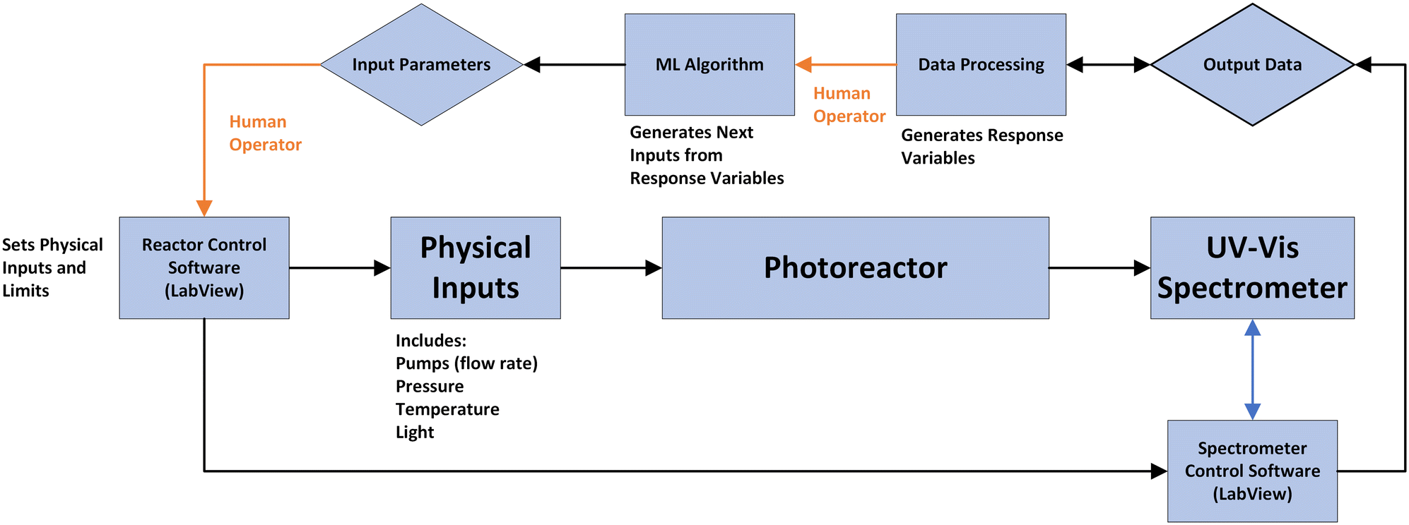 | ||
| Fig. 3 A schematic diagram of data flows in the design of experiments setup for measuring the photocatalytic degradation of an azo dye using a static mixer under continuous flow. As shown the ML algorithm of choice in this setting is a Bayesian optimisation framework which can take observed outcomes of previously performed experiments and suggest the next experiment to perform. Lines in orange indicate where intervention by a human operator is required in the current optimisation loop. | ||
Surrogate model design
A Gaussian process surrogate model was implemented in Python using the GPy framework. The covariance function κ is commonly referred to as the kernel of a Gaussian process,54 with the choice of kernel type being based on assumptions such as smoothness and likely expected patterns in the data. We use a constant mean Gaussian process and the Matérn55 kernel such that:where α is an output scale parameter, r represents the Euclidean distance between design points x1 and x2 and

![[small script l]](https://www.rsc.org/images/entities/i_char_e146.gif) is the length scale parameter of the kernel.
is the length scale parameter of the kernel.
4. Results
Initial scoping experiments were performed to demonstrate a proof-of-concept for the continuous, heterogeneous azo dye decomposition using our catalytic static mixer technology. It was found that the reaction proceeded smoothly with generally high conversions under mild conditions. Continuous monitoring of the reaction output by UV-vis clearly reflected the reactor filling with dye up to the stock solution concentration (72.2 mg L−1). Subsequently, the UV lights were activated, and the dye concentration was observed to decrease to a minimum of 25.1 mg L−1 after an additional 51 min (Fig. 4). After maximum conversion was reached, the dye concentration increased at a linear rate of 9.03 × 10⁻² mg L−1 min−1 (R2 = 0.988). This is attributed to a decay in catalyst activity caused by fouling of the catalyst surface by unreacted dye. This was observed as a persistent orange discolouration of the otherwise white TiO2 surface.56 Deactivation of photocatalytic systems remains a serious issue; yet, despite its importance for commercial applications of the technology, comparatively few studies of the mechanisms of deactivation, regeneration and photocatalyst lifetime have been carried out.25 | ||
| Fig. 4 Photocatalytic decomposition of reactive orange 16 dye over Degussa P25 TiO2 catalyst using a 370 nm led light. The extended 5 h reaction shows an initially high dye conversion followed by a slow decay in catalyst activity. Conditions: residence time = 2.17 min, temperature = 20 °C and reactor pressure = 10 bar. | ||
The observed loss of catalyst activity was found to persist between experiments despite washing the reactor with deionised water. An efficient, in situ method for catalyst regeneration was adapted from Miranda-García (2014) whereby 1 M H2O2 solution (200 mL) was passed over the catalyst surface under UV illumination followed by DI H2O to restore 100% of the original catalytic activity.57 The ability to regenerate the catalyst multiple times using this method was demonstrated in a series of 6 experiments carried out under the same conditions (residence time = 2.17 min, T = 20 °C) with the catalyst regenerated after each experiment. From these the conversion per minute was calculated along with the decay slope (Fig. S1†). It was found that the catalyst could be regenerated several times using this method to recover its original activity. The slope of decay in catalyst activity also remained consistent between runs. This suggests that the rate of catalyst activity loss could be expected to remain stable over the course of several experiments. This allows for multiple experiments to be run without the need for catalyst regeneration between each one if the total amount of dye that is passed over the catalyst is considered by the model.
Further experiments were then carried out at varying flow rates to determine if this affected the decay slope (Fig. S2†). It was found that the rate of decay changed with flow rate. As flow rates increased, the decay slope decreased. This is likely due to (i) shorter contact of the dye and catalyst surface and (ii) more efficient removal of the dye and decomposition products from the catalyst surface under a higher flow velocity. The change in decay slope with flow rate was found to fit a reciprocal function of flow rate (R2 = 0.98). This is consistent with the fact that the time that dye is in contact with the catalyst surface decreases with increasing flow rate. This along with more efficient mixing at higher flow velocities leads to better removal of unreacted dye and reaction products.
To begin optimising the reaction conditions, six experiments were performed to provide the model with data points over a range of conditions (Table S1†). The algorithm considered the measured flow rate (mL min−1), internal reactor temperature (°C), measured initial dye concentration (as determined by UV-vis), conversion (%, UV-vis) and the cumulative total of dye that had passed over the catalyst surface (mg). Reactions were then carried out individually, passing the results to the BO algorithm each time to generate the next experiment. Fig. 5a shows the progress of the algorithm towards an optimal solution. Despite the presence of experimental error and catalyst degradation, the algorithm converged to the optimal conditions (high flow rate and high temperature) within 17 experimental runs. The overall experiment run time was 21 hours. In the system's current state, runs can continue with minimal human supervision, only needing conditions generated by the BO model to be input into the reactor control software and the UV-vis results to be passed back to the BO model for processing and the generation of the next set of conditions. The processes where human intervention is required, (i) inputting values into control software and (ii) processing data to obtain the key performance variable, are both amenable to further automation. As such, if full automation, including a feedback loop system, were implemented then this reaction could have been optimised, completely autonomously, in under one day of operation. The process of optimising processing conditions could feasibly be included within a larger experimental program, for instance optimising catalytic yield from a reaction for each of several different catalysts or reagents.
 | ||
| Fig. 5 (a) Set pump rate and temperature for each experimental run. After the first 6 data points temperature and flow rate are configured according to our BO algorithm. (b) Conversion per minute of azo dye decomposition over several experimental runs. Although the conversion per minute decays because of catalyst degradation between regenerations, the overall trend of conversion per minute is upwards. Experiments were performed either immediately after catalyst regeneration (red points) or without regenerating the catalyst between experiments (blue points). The BO algorithm selected all data points after the first six, as shown. | ||
Fig. 5b shows the improvement in dye conversion per minute of over successive experimental runs. As shown in Fig. 5a, all experiments designed by the BO algorithm have higher flow rate, and from the fourth experiment onwards the algorithm also chooses higher temperatures. Fig. 5b illustrates how catalyst degradation caused periods of reduced conversion, but the BO model was able to continue to improve its designed configurations over time. The algorithm achieves a new high conversion per minute immediately following regeneration.
Addressing catalyst degradation
A novel aspect of our implementation relates to the observed degradation of the catalyst: repeated implementations of the same experimental conditions lead in general to gradually reducing levels of product caused by fouling of the catalyst surface by unreacted dye. Such degradation is a common feature of catalyst systems, though rarely explicitly addressed. This effect leads to inaccuracies in modelling. The chosen reaction, as Fig. 6 shows, is one in which the effect is very strong – but even in less marked cases, optimisation methods will be at an advantage if they are able to adjust for such effects.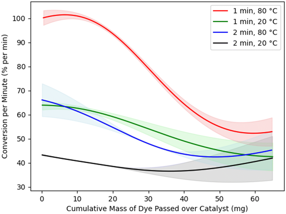 | ||
| Fig. 6 Estimated changes in catalyst conversion per minute in terms of the amount of dye that has passed over the catalyst, for residence times of 1 or 2 minutes and temperatures of 20 or 80 °C. Shaded regions represent 95% confidence intervals. | ||
Our approach to address this issue is to incorporate degradation in the BO surrogate model. We include the total amount of dye that has passed over the catalyst since the most recent catalyst regeneration in the model to allow for gradual catalyst degradation. This explicitly accommodates the likely physical mechanism for catalyst degradation and is thus more appropriate than simply allowing for gradual degradation over time.
While the BO algorithm maximises reaction yield, it simultaneously builds up an internal representation of the effect of catalyst degradation. Fig. 6 is extracted from the model to depict this effect for various reactor setups (residence times of 1 or 2 minutes and temperatures of 20 or 80 °C). The model thus accounts for catalyst degradation by predicting not just one reaction yield for each reactor configuration, but a range depending on the amount of dye that has passed over the catalyst since it was last regenerated.
The model correctly predicts a downward trend in conversion as more dye is passed over the catalyst. We note that this catalyst curve was not obtained by running specific control experiments to determine the effect of catalyst degradation between catalyst regenerations; rather, it is modelled automatically as part of the overall process of optimising conversion. Catalyst degradation has a marked effect in the reaction studied. Not only does our method successfully negotiate this issue, but it simultaneously provides an accurate model of the size of the effect ‘for free’, rather than demanding extra calibration studies to be performed. The catalyst degradation curves found by the BO algorithm also tend to be linear, at least in the areas with narrower confidence intervals where the algorithm has more data. But our method does not require the catalyst degradation to be linear. It only requires it to be repeatable.
Fig. 6 also shows the uncertainty of the surrogate model. The shaded regions around the solid lines represent 95% confidence intervals for the mean conversion per minute. The confidence intervals are narrow where there is more data, particularly for the red line corresponding to shorter residence time and higher temperature, which is close to the optimal configuration for this reaction.
Outside of the data range that was well covered by experimentation, Fig. 6 suggests the overall trend of catalyst degradation changes, although with much greater model uncertainty. Such a change in trend seems unlikely, and more data would refine these estimates; however, experimentation was halted when the aim of optimising conversion per minute was achieved. Fig. 6 thus highlights an important efficiency of our approach: enough data is obtained to model the effects of catalyst degradation with a high degree of accuracy in the optimal range of reaction parameters. Experimental resources are not spent establishing these effects with accuracy in other regions of the design space, as would be necessary if the catalyst degradation effects were to be modelled in a separate, preliminary study. In most practical cases, such use of experimental resources would be wasted, as it would relate to suboptimal reaction conditions that are of no interest.
Exploring the surrogate model
Fig. 7 shows the conversion model at four stages in the experiment, illustrating its convergence towards the optimum. The objective function f is represented using heatmaps over the possible temperature and flow rate configurations. Estimates are shown for catalysts immediately after regeneration.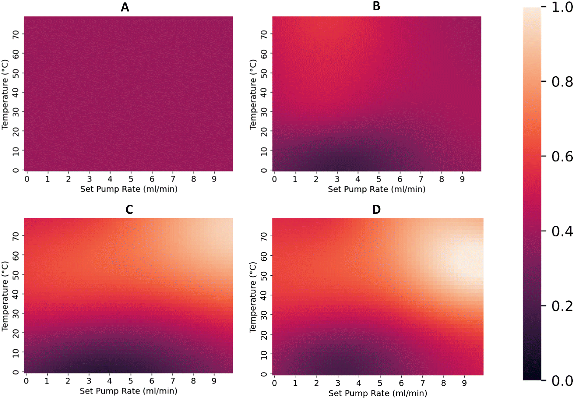 | ||
| Fig. 7 Estimates from the surrogate model in the form of heatmaps. Shown in this figure are the normalised conversion per minute estimates at four stages of experimentation. The top left heatmap (A) shows model estimates after the first experiment is performed; we can see the model assigns equal potential to all possible temperature/flow rate configurations. As we observe more experimental outcomes (B and C, after 6 and 12 experiments respectively), the model begins to assign higher potential value to high temperature and flow rate configurations. The final model shown in heatmap D, after all 17 experiments, estimates higher conversion rates for setups with high flow rate, and especially for those with higher temperatures. | ||
The top left heatmap A shows the initial model's estimates after observing only one experiment. It has assigned a flat and uniform conversion over all the possible configurations, indicating that each configuration has equal potential for maximising the objective. Heatmap B shows the model's estimates after it has observed conversion values for the initial training set of experiments (Table S1†). Traditional design of experiment principles were used to explore the range of each variable, including some replication to measure purely random variations in the system (this control assessment is necessary to ensure the signal-to-noise ratio in the data is high enough for optimisation to proceed). The initial conditions were chosen intentionally as a kind of ‘worst-case scenario’ to test the optimisation algorithm: higher temperature and flow rates are typically favourable for conversion per minute, but the replicates were chosen at low temperatures and flow rates whilst high temperature/high flow rate combinations were not assessed. The catalyst was not regenerated for the last two observations, which means the benefit of increasing the temperature was offset against catalyst degradation effects. The BO algorithm was thus left to disentangle these effects through subsequent experimentation.
The heatmap in Fig. 7C shows the outcome after six additional experimental outcomes have been observed. We can see that with these additional six observed outcomes, the model now has a much stronger tendency to favour both high temperatures and high flow rates. With an additional five experiments as shown in Fig. 7D, the BO model continues to favour high temperatures and flow rates.
5. Conclusion
Machine-learning assisted synthesis and experimental design show great promise in aiding the optimisation of multiparameter problems within the field of chemistry. Herein we have demonstrated a BO algorithm for optimising a chemical system that automatically measures and corrects for the effects of catalyst degradation. This model has been demonstrated to converge towards optimal experimental conditions despite being initialised with a pool of only six training data points, consisting of observations far from the optimum. Despite the presence of experimental error and catalyst degradation the BO algorithm converged on configurations with high flow rate and high temperature as giving the highest conversion per minute. The optimum was found in 17 experimental runs, with an overall experiment run time of 21 hours. With full automation of the reactor into a closed loop system this optimisation process could have been carried out in under one day with almost no human intervention. This BO algorithm was applied to the evaluation of a novel TiO2 coated CSM for continuous photocatalytic degradation of the azo dye reactive orange 16. With an internal reactor temperature of 67 °C, residence time of 49 sec and freshly regenerated TiO2 catalyst, a peak conversion of 102% min−1 was achieved. These results were achieved whilst the BO algorithm was presented with the issue of catalyst degradation. This was partially overcome by the introduction of an in situ regeneration procedure developed for the CSM supported TiO2 catalyst. Despite the changing catalyst activity, the BO model was able to continue to optimise the conversion per minute and reach an optimum.Conflicts of interest
There are no conflicts to declare.References
- S. Krishnadasan, R. J. C. Brown, A. J. deMello and J. C. deMello, Intelligent Routes to the Controlled Synthesis of Nanoparticles, Lab Chip, 2007, 7(11), 1434–1441, 10.1039/B711412E.
- L. M. Baumgartner, C. W. Coley, B. J. Reizman, K. W. Gao and K. F. Jensen, Optimum Catalyst Selection over Continuous and Discrete Process Variables with a Single Droplet Microfluidic Reaction Platform, React. Chem. Eng., 2018, 3(3), 301–311, 10.1039/C8RE00032H.
- M. I. Jeraal, S. Sung and A. A. Lapkin, A Machine Learning-Enabled Autonomous Flow Chemistry Platform for Process Optimization of Multiple Reaction Metrics, Chem.: Methods, 2021, 1(1), 71–77, DOI:10.1002/cmtd.202000044.
- C. M. Carliell, S. J. Barclay, C. Shaw, A. D. Wheatley and C. A. Buckley, The Effect of Salts Used in Textile Dyeing on Microbial Decolourisation of a Reactive Azo Dye, Environ. Technol., 1998, 19(11), 1133–1137, DOI:10.1080/09593331908616772.
- E. A. Clarke and R. Anliker, Organic Dyes and Pigments, in Anthropogenic Compounds, The Handbook of Environmental Chemistry, Springer, Berlin, Heidelberg, 1980, pp. 181–215, DOI:10.1007/978-3-540-38522-6_7.
- A. Bafana and T. Chakrabarti, Lateral Gene Transfer in Phylogeny of Azoreductase Enzyme, Comput. Biol. Chem., 2008, 32(3), 191–197, DOI:10.1016/j.compbiolchem.2008.03.003.
- M. A. Brown and S. C. De Vito, Predicting Azo Dye Toxicity, Crit. Rev. Environ. Sci. Technol., 1993, 23(3), 249–324, DOI:10.1080/10643389309388453.
- International Agency for Research on Cancer, L.; Lyon, W. G. on the E. of the C. R. of C. to H. eng 15–22 J. 1982. IARC Monographs on the Evaluation on the Carcinogenic Risk of Chemicals to Humans; v. 30: Miscellaneous Pesticides; Lyon (France) IARC, 1983, https://scholar.google.com/scholar_lookup?title=IARC+monographs+on+the+evaluation+on+the+carcinogenic+risk+of+chemicals+to+humans%3B+v.+30%3A+Miscellaneous+pesticides&author=International+Agency+for+Research+on+Cancer%2C+Lyon+%28France%29%0A++++eng&publication_year=1983, (accessed 2022-08-31).
- K.-T. Chung, Azo Dyes and Human Health: A Review, J. Environ. Sci. Health, Part C: Environ. Carcinog. Ecotoxicol. Rev., 2016, 34(4), 233–261, DOI:10.1080/10590501.2016.1236602.
- G. McMullan, C. Meehan, A. Conneely, N. Kirby, T. Robinson, P. Nigam, I. M. Banat, R. Marchant and W. F. Smyth, Microbial Decolourisation and Degradation of Textile Dyes, Appl. Microbiol. Biotechnol., 2001, 56(1–2), 81–87, DOI:10.1007/s002530000587.
- A. Bafana, S. S. Devi and T. Chakrabarti, Azo Dyes: Past, Present and the Future, Environ. Rev., 2011, 19, 350–371, DOI:10.1139/a11-018.
- N. Daneshvar, M. Rabbani, N. Modirshahla and M. A. Behnajady, Kinetic Modeling of Photocatalytic Degradation of Acid Red 27 in UV/TiO2 Process, J. Photochem. Photobiol., A, 2004, 168(1–2), 39–45, DOI:10.1016/j.jphotochem.2004.05.011.
- M. Behnajady, N. Modirshahla and R. Hamzavi, Kinetic Study on Photocatalytic Degradation of C.I. Acid Yellow 23 by ZnO Photocatalyst, J. Hazard. Mater., 2006, 133(1–3), 226–232, DOI:10.1016/j.jhazmat.2005.10.022.
- M. Khanahmadi, M. Hajaghazadeh, F. Nejatzadeh-Barandozi and F. Gholami-Borujeni, Photocatalytic Oxidation Process (UV-Fe2O3) Efficiency for Degradation of Hydroquinone, Desalin. Water Treat., 2018, 106, 305–311, DOI:10.5004/dwt.2018.22087.
- T. T. Nguyen, S.-N. Nam, J. Son and J. Oh, Tungsten Trioxide (WO3)-Assisted Photocatalytic Degradation of Amoxicillin by Simulated Solar Irradiation, Sci. Rep., 2019, 9(1), 9349, DOI:10.1038/s41598-019-45644-8.
- E. Kusmierek, A CeO2 Semiconductor as a Photocatalytic and Photoelectrocatalytic Material for the Remediation of Pollutants in Industrial Wastewater: A Review, Catalysts, 2020, 10(12), 1435, DOI:10.3390/catal10121435.
- W. Z. Tang and A. Huren, UV/TiO2 Photocatalytic Oxidation of Commercial Dyes in Aqueous Solutions, Chemosphere, 1995, 31(9), 4157–4170, DOI:10.1016/0045-6535(95)80015-D.
- R. Thiruvenkatachari, S. Vigneswaran and I. S. Moon, A Review on UV/TiO2 Photocatalytic Oxidation Process (Journal Review), Korean J. Chem. Eng., 2008, 25(1), 64–72, DOI:10.1007/s11814-008-0011-8.
- M. S. Mehos and C. S. Turchi, Field Testing Solar Photocatalytic Detoxification on TCE-Contaminated Groundwater, Environ. Prog., 1993, 12(3), 194–199, DOI:10.1002/ep.670120308.
- S. Malato, P. Fernández-Ibáñez, M. I. Maldonado, J. Blanco and W. Gernjak, Decontamination and Disinfection of Water by Solar Photocatalysis: Recent Overview and Trends, Catal. Today, 2009, 147(1), 1–59, DOI:10.1016/j.cattod.2009.06.018.
- J. A. Byrne, B. R. Eggins, N. M. D. Brown, B. McKinney and M. Rouse, Immobilisation of TiO2 Powder for the Treatment of Polluted Water, Appl. Catal., B, 1998, 17(1), 25–36, DOI:10.1016/S0926-3373(97)00101-X.
- O. Legrini, E. Oliveros and A. M. Braun, Photochemical Processes for Water Treatment, Chem. Rev., 1993, 93(2), 671–698, DOI:10.1021/cr00018a003.
- S. K. Loeb, P. J. J. Alvarez, J. A. Brame, E. L. Cates, W. Choi, J. Crittenden, D. D. Dionysiou, Q. Li, G. Li-Puma, X. Quan, D. L. Sedlak, T. David Waite, P. Westerhoff and J.-H. Kim, The Technology Horizon for Photocatalytic Water Treatment: Sunrise or Sunset?, Environ. Sci. Technol., 2019, 53(6), 2937–2947, DOI:10.1021/acs.est.8b05041.
- M. A. Behnajady, N. Modirshahla, N. Daneshvar and M. Rabbani, Photocatalytic Degradation of an Azo Dye in a Tubular Continuous-Flow Photoreactor with Immobilized TiO2 on Glass Plates, Chem. Eng. J., 2007, 127(1), 167–176, DOI:10.1016/j.cej.2006.09.013.
- M. G. Alalm, R. Djellabi, D. Meroni, C. Pirola, C. L. Bianchi and D. C. Boffito, Toward Scaling-Up Photocatalytic Process for Multiphase Environmental Applications, Catalysts, 2021, 11(5), 562, DOI:10.3390/catal11050562.
- M. A. Behnajady and N. Modirshahla, Kinetic Modeling on Photooxidative Degradation of C.I. Acid Orange 7 in a Tubular Continuous-Flow Photoreactor, Chemosphere, 2006, 62(9), 1543–1548, DOI:10.1016/j.chemosphere.2005.05.027.
- A. Salhi, S. Esserrar, B. Nechchadi, M. El Amine Ghanjaoui, A. Aguedache, M. El Krati and S. Tahiri, Application of Titanium Dioxide Immobilized on a Cellulosic Material for the Photocatalytic Degradation of Acid Black 24 Dye in a Continuous Flow Cascade Reactor, Environ. Sci. Pollut. Res., 2022, 29, 46778–46787, DOI:10.1007/s11356-022-19210-1.
- F. Azizpour and F. Qaderi, Optimization, Modeling and Uncertainty Investigation of Phenolic Wastewater Treatment by Photocatalytic Process in Cascade Reactor, Environ. Dev. Sustain., 2020, 22(7), 6315–6342, DOI:10.1007/s10668-019-00480-8.
- W. Henry, J. Tsanaktsidis, C. Hornung, A. J. Urban, D. Fraser, D. R. Gunasegaram, M. D. Horne, J.-P. Veder and T. Rodopoulos, Static Mixers for Continuous Flow Catalytic Reactors, WO2017106916A1, 2017, https://patents.google.com/patent/WO2017106916A1/en (accessed 2024-01-05).
- Catalytic Static Mixers - CSMs. FloWorks, https://research.csiro.au/floworks/research/catalytic-static-mixers/, (accessed 2022-09-01).
- Y. Zhu, B. Bin Mohamad Sultan, X. Nguyen and C. Hornung, Performance Study and Comparison between Catalytic Static Mixer and Packed Bed in Heterogeneous Hydrogenation of Vinyl Acetate, J. Flow Chem., 2021, 11(3), 515–523, DOI:10.1007/s41981-021-00152-7.
- R. Legg, C. Zhang, M. Bourchier, S. Cole, I. Martinez-Botella, X. Nguyen, Y. Zhu, W. Liew, S. Saubern, J. Tsanaktsidis and C. H. Hornung, Durability Study of 3D-Printed Catalytic Static Mixers for Hydrogenations in Chemical Manufacturing, Chem. Ing. Tech., 2022, 94(7), 1017–1023, DOI:10.1002/cite.202200060.
- HANU™ HX 15, Creaflow, https://www.creaflow.be/hanutm-hx-15, (accessed 2022-09-01).
- A. M. Díez, F. C. Moreira, B. A. Marinho, J. C. A. Espíndola, L. O. Paulista, M. A. Sanromán, M. Pazos, R. A. R. Boaventura and V. J. P. Vilar, A Step Forward in Heterogeneous Photocatalysis: Process Intensification by Using a Static Mixer as Catalyst Support, Chem. Eng. J., 2018, 343, 597–606, DOI:10.1016/j.cej.2018.03.041.
- T. F. C. V. Silva, P. Peri, A. S. Fajardo, L. O. Paulista, P. A. Soares, C. A. Martínez-Huitle and V. J. P. Vilar, Solar-Driven Heterogeneous Photocatalysis Using a Static Mixer as TiO2-P25 Support: Impact of Reflector Optics and Material, Chem. Eng. J., 2022, 435, 134831, DOI:10.1016/j.cej.2022.134831.
- D. F. S. Morais, R. A. R. Boaventura, F. C. Moreira and V. J. P. Vilar, Advances in Bromate Reduction by Heterogeneous Photocatalysis: The Use of a Static Mixer as Photocatalyst Support, Appl. Catal., B, 2019, 249, 322–332, DOI:10.1016/j.apcatb.2019.02.070.
- V. H. A. van Dijk, G. Simmelink and G. Mul, The Influence of Water Vapour on the Photocatalytic Oxidation of Cyclohexane in an Internally Illuminated Monolith Reactor, Appl. Catal., A, 2014, 470, 63–71, DOI:10.1016/j.apcata.2013.10.035.
- A. Mandoli, Catalyst Recycling in Continuous Flow Reactors, in Catalyst Immobilization, John Wiley & Sons, Ltd, 2020, pp. 257–306, DOI:10.1002/9783527817290.ch8.
- Design 202110400 | IP Australia | Australian Design Search, https://search.ipaustralia.gov.au/designs/search/details/202110400?s=3310a468-8280-405f-937a-e196f7c7a474, (accessed 2023-05-18).
- A. D. Bull and A. Bull, Convergence Rates of Efficient Global Optimization Algorithms, 26.
- B. J. Shields, J. Stevens, J. Li, M. Parasram, F. Damani, J. I. M. Alvarado, J. M. Janey, R. P. Adams and A. G. Doyle, Bayesian Reaction Optimization as a Tool for Chemical Synthesis, Nature, 2021, 590(7844), 89–96, DOI:10.1038/s41586-021-03213-y.
- F. Hutter, H. H. Hoos and K. Leyton-Brown, Sequential Model-Based Optimization for General Algorithm Configuration, in Learning and Intelligent Optimization, Lecture Notes in Computer Science, ed. C. A. C. Coello, Springer, Berlin, Heidelberg, 2011, vol. 6683, pp. 507–523, DOI:10.1007/978-3-642-25566-3_40.
- B. Shahriari, K. Swersky, Z. Wang, R. P. Adams and N. de Freitas, Taking the Human Out of the Loop: A Review of Bayesian Optimization, Proc. IEEE, 2016, 104(1), 148–175, DOI:10.1109/JPROC.2015.2494218.
- P. I. Frazier, A Tutorial on Bayesian Optimization, arXiv, 2018, preprint, DOI:10.48550/arXiv.1807.02811.
- D. Xue, P. V. Balachandran, J. Hogden, J. Theiler, D. Xue and T. Lookman, Accelerated Search for Materials with Targeted Properties by Adaptive Design, Nat. Commun., 2016, 7(1), 11241, DOI:10.1038/ncomms11241.
- A. Vahid, S. Rana, S. Gupta, P. Vellanki, S. Venkatesh and T. Dorin, New Bayesian-Optimization-Based Design of High-Strength 7xxx-Series Alloys from Recycled Aluminum, JOM, 2018, 70(11), 2704–2709, DOI:10.1007/s11837-018-2984-z.
- C. Li, Rubín de Celis, D. Leal, S. Rana, S. Gupta, A. Sutti, S. Greenhill, T. Slezak, M. Height and S. Venkatesh, Rapid Bayesian Optimisation for Synthesis of Short Polymer Fiber Materials, Sci. Rep., 2017, 7(1), 5683, DOI:10.1038/s41598-017-05723-0.
- R.-R. Griffiths and J. M. Hernández-Lobato, Constrained Bayesian Optimization for Automatic Chemical Design, arXiv, 2019, preprint, DOI:10.48550/arXiv.1709.05501.
- F. Häse, L. M. Roch, C. Kreisbeck and A. Aspuru-Guzik, Phoenics: A Bayesian Optimizer for Chemistry, ACS Cent. Sci., 2018, 4(9), 1134–1145, DOI:10.1021/acscentsci.8b00307.
- M. Rubens, J. H. Vrijsen, J. Laun and T. Junkers, Precise Polymer Synthesis by Autonomous Self-Optimizing Flow Reactors, Angew. Chem., Int. Ed., 2019, 58(10), 3183–3187, DOI:10.1002/anie.201810384.
- B. Burger, P. M. Maffettone, V. V. Gusev, C. M. Aitchison, Y. Bai, X. Wang, X. Li, B. M. Alston, B. Li, R. Clowes, N. Rankin, B. Harris, R. S. Sprick and A. I. Cooper, A Mobile Robotic Chemist, Nature, 2020, 583(7815), 237–241, DOI:10.1038/s41586-020-2442-2.
- Q. Liang, A. E. Gongora, Z. Ren, A. Tiihonen, Z. Liu, S. Sun, J. R. Deneault, D. Bash, F. Mekki-Berrada, S. A. Khan, K. Hippalgaonkar, B. Maruyama, K. A. Brown, J. Fisher III and T. Buonassisi, Benchmarking the Performance of Bayesian Optimization across Multiple Experimental Materials Science Domains, npj Comput. Mater., 2021, 7(1), 1–10, DOI:10.1038/s41524-021-00656-9.
- J. Mockus, On Bayesian Methods for Seeking the Extremum, p. 5 Search PubMed.
- F. Jäkel, B. Schölkopf and F. A. Wichmann, A Tutorial on Kernel Methods for Categorization, J. Math. Psychol., 2007, 51(6), 343–358, DOI:10.1016/j.jmp.2007.06.002.
- J. Gardner, G. Pleiss, K. Q. Weinberger, D. Bindel and A. G. Wilson, GPyTorch: Blackbox Matrix-Matrix Gaussian Process Inference with GPU Acceleration, in Advances in Neural Information Processing Systems, Curran Associates, Inc., 2018, vol. 31 Search PubMed.
- D. L. Cunha, A. Kuznetsov, C. A. Achete, A. E. da H. Machado and M. Marques, Immobilized TiO2 on Glass Spheres Applied to Heterogeneous Photocatalysis: Photoactivity, Leaching and Regeneration Process, PeerJ, 2018, 6, 4464, DOI:10.7717/peerj.4464.
- N. Miranda-García, S. Suárez, M. I. Maldonado, S. Malato and B. Sánchez, Regeneration Approaches for TiO2 Immobilized Photocatalyst Used in the Elimination of Emerging Contaminants in Water, Catal. Today, 2014, 230, 27–34, DOI:10.1016/j.cattod.2013.12.048.
Footnote |
| † Electronic supplementary information (ESI) available. See DOI: https://doi.org/10.1039/d3re00570d |
| This journal is © The Royal Society of Chemistry 2024 |