
 Open Access Article
 This Open Access Article is licensed under a
 Creative Commons Attribution 3.0 Unported Licence
Efficient and labor-saving Ru/C catalysts for the transformation of levulinic acid into γ-valerolactone under mild reaction conditions†
Zaira
Ruiz-Bernal
,
M. Ángeles
Lillo-Ródenas
 and
M. Carmen
Román-Martínez
*
and
M. Carmen
Román-Martínez
*
MCMA group, Department of Inorganic Chemistry and Materials Institute (IUMA), Faculty of Sciences, University of Alicante, Ap. 99, E-03080 Alicante, Spain. E-mail: mcroman@ua.es; Tel: +34 9659 03975
First published on 8th November 2023
Abstract
Ru/C catalysts for the transformation of levulinic acid into gamma-valerolactone have been prepared using carbon materials with different textural and chemical properties, and morphology. In the mild reaction conditions used (70 °C, 15 bar H2, 1 h), all the reduced catalysts are active and selective, with similar behavior independently of the support's properties. Surprisingly, the un-reduced (as prepared) catalysts show also catalytic activity, which varies (from moderate to high) with the carbon support type, indicating that an in situ (under reaction) reduction process takes place. The catalysts prepared with the supports of lower surface chemistry are almost as active as their reduced counterparts, whereas those prepared with rich surface chemistry supports are noticeably less active, but become activated in consecutive runs. The size of the developed Ru particles depends on the reduction conditions (i.e., reduction treatment at 250 °C or reaction conditions) and is highly influenced by the support's surface chemistry, which determines the metal–support interaction.
Introduction
The urgent need to produce energy and chemical products in sustainable and environmentally friendly ways has prompted researchers to develop cleaner and more efficient processes. In this context, the transformation of lignocellulosic biomass residues to obtain fuels and other high value-added products is a relevant issue. Lignocellulosic biomass constitutes an abundant raw material from which useful platform chemicals, like furfural (FAL) and levulinic acid (LA), can be obtained through the catalytic dehydration of six- and five-carbon atom sugars, as shown in Fig. 1.1,2 | ||
| Fig. 1 Reaction pathway of lignocellulosic biomass conversion to platform molecules and value-added products. | ||
Lignocellulosic biomass is mainly composed of cellulose, hemicellulose and lignin, being a small amount of inorganic salts also usually present. The proportion of the main components depends on the biomass origin, e.g., hardwood contains 40–55 wt% cellulose, 24–40 wt% hemicellulose, and 18–25 wt% lignin, while for softwood these constituents are 45–50 wt%, 25–35 wt% and 25–35 wt%, respectively.3
Acid hydrolysis of lignocellulosic biomass leading to LA can be described by the following consecutive reactions of cellulose: (i) hydrolysis into glucose, (ii) isomerization of glucose to fructose, (iii) dehydration of glucose and fructose (hexoses) to HMF, and (iv) rehydration of HMF to LA and formic acid.3–5
LA exhibits a high industrial potential for the production of important platform molecules and high value-added chemicals, including 1,4-pentanodiol (PND), valeric acid (VA), γ-valerolactone (GVL), 2-methyltetrahydrofuran (2-MTHF), diphenolic acid and levulinates.6–8
Among the mentioned products, γ-valerolactone (GVL) is considered the most outstanding feedstock derived from LA. It can be used in direct applications, such as in the production of fragrances, as food ingredient, green solvent,9 or fuel additive.3,4 In this last application, GVL has shown to perform better than ethanol due to its lower vapour pressure and higher energy content, and also because it decreases the CO and smoke content in exhaust gases compared to neat diesel.10,11 Therefore, GVL is becoming a promising additive in the production of liquid fuels.9,12,13 Besides, GVL presents interesting practical properties as it is biodegradable, safe, and non-toxic.3 However, the future use of GVL derived from lignocellulosic biomass will be strongly conditioned by the availability of an effective catalytic process. GVL can be obtained from LA by a two-step process that occurs through any (or a combination) of the following routes12,14,15 (Fig. 2): a) in the gas phase, via LA dehydration (enolization process) to produce angelica lactone (AL), which is further hydrogenated, or b) in the liquid phase, via hydrogenation of the carbonyl group of LA at the C4 position to obtain 4-hydroxypentanoic acid (HPA), a thermolabile intermediate compound, followed by a lactonization process (intramolecular esterification) favoured by acid catalysts. Hydrogenation, and dehydration and lactonization steps require adequate catalysts, metallic and acidic, respectively.
 | ||
| Fig. 2 Scheme of hydrogenation routes of LA to produce GVL, based on the information from references.14,15 | ||
To enhance the acidity of the reaction medium and to increase the activity, several researchers (i.e. Galletti et al.16) have incorporated acidic agents into the catalytic system, either as mineral acids in solution or as solid acids, such as Amberlyst A-15, Amberlyst A-70 or niobium phosphate. However, it would be interesting to develop bifunctional catalysts, including both metal and acidic functions.
This can be achieved using acidic supports on which metal active phases such as Rh, Pd, Pt, or Ru are deposited.17–19 Such catalysts enhance the selectivity to GVL and accelerate the esterification process of HPA14,20 and, among them, Ru-based catalysts have shown to be very active.14,21–23 Regarding the catalyst supports, carbon materials have shown interesting properties as they are very versatile in terms of surface area, porosity and surface chemistry, and allow to achieve suitable metal dispersion and metal–support interaction.21,24–26 Besides, they are thermally and chemically stable.27,28
Several researchers have focused their work on developing greener processes for the transformation of LA into GVL. Usually, the target experimental variables to improve the system are the nature and content of the metal used as active phase,29,30 the type of support,16,22,24–26 including nature and physico-chemical properties,16,31 and the operation conditions, such as temperature, pressure and/or reaction time.9 Some of the indicated studies have led to good results, although in many cases the catalysts' preparation procedures and the catalytic methods involve non-green solvents and high-priced activation processes and/or reaction conditions. Considering this, the present work focuses on the search for an efficient catalytic transformation of LA to GVL using mild temperature conditions and simple and unsophisticated heterogeneous bifunctional catalysts. The use of carbon materials as supports to prepare Ru-based catalysts could accomplish the requirements of simplicity and low cost and, as the family of carbon materials is very broad, it is feasible to find a suitable support of this nature.
The main properties of carbon materials affecting the efficiency of the M/C catalysts are surface area and porosity, and surface chemistry.32 Porosity determines the location of the active species and the diffusion of reactants and products, while surface chemistry modulates the support's wettability and the metal support interaction, being able to provide some active sites (like acidic sites). In general, carbon surface chemistry is a complex issue, as both the nature and amount of surface oxygen groups can largely vary, and its effect in catalytic applications is strongly dependent on the catalytic system (supported active phase, preparation method, reaction conditions, etc.).
For instance, Zhu et al.,33 report that oxidation treatments over a commercial activated carbon used to prepare Ru/C catalysts for ammonia synthesis make the support's surface more amenable to metal dispersion, and a high concentration of surface oxygen groups leads to high Ru dispersion and activity. Another example is reported by Zanutelo et al.,34 who studied the modification of surface oxygen content of Ru/C catalysts used in the partial hydrogenation of benzene in liquid phase. The obtained results showed that the catalytic performance of the Ru/C catalysts was influenced by certain functional groups existing on the carbon surface: carbonyl groups led to a decrease of the catalytic activity and selectivity, while the presence of carboxylic groups increased the cyclohexene yield.
Considering all these features of carbon materials, for this study, five carbon materials with different textural and chemical properties, and morphology, have been selected. They are carbon materials of different nature that do not constitute a series in any of their properties and have been selected with the purpose of testing spherically shaped carbons that will afford an easy manipulation of the catalyst, and conventional (granular and powdery) activated carbons. The study allows investigating the effect of the carbon support in achieving different interactions with the metal precursor and the consequences in the final properties of the catalysts.
With the aim of coming up with a simpler and cheaper process, the influence on the catalytic activity of skipping the common catalysts reduction treatment has been studied.
Thus, this work deals with testing prepared Ru/C catalysts for the conversion of LA into GVL under mild reaction conditions, and embraces a thorough analysis of the effect of the properties (texture and surface chemistry) of a set of different carbon supports on the catalytic activity of Ru/C catalysts: the use of scarcely reported spherically shaped supports and the important point of skipping the catalyst's reduction thermal treatment. All these issues constitute the novelties of the present study with respect to those previously reported, and the obtained conclusions could be helpful in reducing the complexity and costs of the catalytic process.
Materials and methods
Materials
The following carbon materials have been used as supports to prepare Ru/C catalysts:Carbons named IC-1 and IC-2, provided by Immutrix Therapeutics (USA), have spherical morphology with mean size of 0.15 mm and 0.5 mm, respectively, and have been obtained by polymerization of phenol–formaldehyde resin, resembling the synthesis of carbon xerogels, according to a patented production process.35 Preparation of IC-1 includes the carbonization with CO2 at 700 °C, and IC-2 is physically activated with CO2 at 1050 °C during 5 h. According to the producer, these carbon materials contain large transport pores (26–50 nm in IC-1 and 150 nm in IC-2).
Carbon named ACGE, from Gun-Ei Chemical Industry (Japan), is also spherically shaped with average size in the range of 0.1–0.5 mm and was prepared by activation of a carbonized material obtained from phenolic resins.
Carbons IC-1 and ACGE have also been used after milling in order to determine any particular influence of the spherical morphology. Milling was performed using a planetary ball mill (PM 200, Retsch Company) in the following conditions: 500 rpm, 1 h, 3.5 g agate balls per g carbon, and reverse rotation (1 min stop period). The ground samples are named IC-1g and ACGEg.
Carbons SA-30 and WV-1100 are commercial activated carbons supplied by MeadWestvaco (now Ingevity Corporation (North Charleston, SC, USA)). SA-30 is a fine powder (<0.1 mm) and WV-1100 presents granular morphology (∼1 mm, 10 × 25 mesh).
RuCl3 (45–55 wt% Ru), levulinic acid (98%), and gamma-valerolactone (99%) have been purchased from Sigma Aldrich.
Preparation of catalysts
Carbon materials (dried at 115 °C, 24 h) were mixed with an aqueous RuCl3 solution (18 mL solution per g support) of the appropriate concentration to obtain catalysts with nominal 1 wt% Ru. The mixture was mechanically stirred for 24 h, then ultrasonicated for 3 h and, finally, the solvent was evaporated in a stove (115 °C, 20 h). The catalysts are named Ru/C, where C is, in each case, the name of the carbon material, as indicated above.A fraction of the prepared catalysts was submitted to a reduction treatment (250 °C, 75 mL min−1 H2, 4 h). The nomenclature of the reduced samples includes “R” as a superscript (RuR/C).
Characterization of supports and catalysts
To determine the actual ruthenium content of the catalysts, the samples were digested using aqua regia (HNO3![[thin space (1/6-em)]](https://www.rsc.org/images/entities/char_2009.gif) :HCl (1:3), 4 mL) and the following heating program: 20 °C min−1 to 100 °C, 5 °C min−1 to 170 °C and 7 °C min−1 to 240 °C with 15 min soaking time. After cooling down to 30 °C, the obtained solutions were diluted to 15 mL with milli-Q water and then, they were analyzed by inductively coupled plasma mass spectrometry (ICP-MS, ICP Agilent 7700x coupled to MS Agilent 8900). In all catalysts, the actual Ru loading ranged between 0.7 and 0.8 wt%.
:HCl (1:3), 4 mL) and the following heating program: 20 °C min−1 to 100 °C, 5 °C min−1 to 170 °C and 7 °C min−1 to 240 °C with 15 min soaking time. After cooling down to 30 °C, the obtained solutions were diluted to 15 mL with milli-Q water and then, they were analyzed by inductively coupled plasma mass spectrometry (ICP-MS, ICP Agilent 7700x coupled to MS Agilent 8900). In all catalysts, the actual Ru loading ranged between 0.7 and 0.8 wt%.
The specific surface area and porosity of the supports and catalysts were determined by a combination of techniques. On one hand, N2 and CO2 adsorption isotherms, at −196 °C and 0 °C, respectively,36–38 were obtained using a volumetric Autosorb-6B apparatus (Quantachrome Instruments). The samples were previously degassed at 250 °C for 4 h. On the other hand, Hg porosimetry was measured using a POREMASTER-60 GT equipment (Quantachrome Instruments). In this case, the samples were previously dried (110 °C, 12 h). The pore size distribution was determined using the Washburn equation, which relates applied pressure and pore diameter.38
N2 adsorption data allow the determination of the apparent surface area (SBET) and the total micropore volume (VDR,N2) (pores smaller than 2 nm) by application of the BET and Dubinin–Radushkevich equations, respectively, and also allows estimating the volume of mesopores of size from 2.0 to 7.5 nm, from the volume of nitrogen adsorbed between 0.2 and 0.7 P/Po, named Vmeso,N2.37–40 CO2 adsorption isotherms were used to determine the volume of narrow micropores (VDR,CO2), those smaller than 0.7 nm.39–41 The volume of supermicropores, i.e. pores with size ranging 0.7–2.0 nm (Vsuper micro), was calculated as the difference between VDR,N2, and VDR,CO2.39–41 Hg porosimetry allowed determining the volume of mesopores of size between 7.5 and 50 nm (Vmeso,Hg) and, also, the volume of macropores (pores larger than 50 nm) (Vmacro,Hg). The total volume of mesopores was calculated as VT,meso = Vmeso,N2 + Vmeso,Hg.
Temperature programmed desorption (TPD) measurements were performed to study the surface chemistry of the carbon materials. For that purpose, 10 mg sample were heated at 20 °C min−1 in He flow (100 mL min−1) up to 950 °C in a thermobalance (TA-SDT Q600) coupled to a mass spectrometer (Thermostar, Balzers), what allows the simultaneous determination of weight loss and analysis of evolved gases (CO2, CO, and H2O).
The reducibility of the catalysts and the interaction between metal and support were tested by temperature programmed reduction with H2 (H2-TPR), performed in Pulse Chemisorb 2705 (Micromeritics) equipped with a TCD (thermal conductivity detector). The H2-TPR experiments were carried out using 20 mg sample and a 5% H2/Ar flow (50 mL min−1), heating at 10 °C min−1 from room temperature to 950 °C. It can be mentioned that TPR measurements were also carried out following the process by mass spectrometry in order to avoid dealing with the interferences due to the decomposition of surface oxygen groups that come about in the analysis by TCD. However, it was not possible to properly appreciate the variations of the hydrogen concentration and, thus, this technique resulted in low sensitivity.
Transmission electron microscopy (TEM, JEOL JEM-2010 (200 keV) with digital camera GATAN ORIUS SC600, and TALOS F200X Microscope coupled to EDX system) was used to analyze the mean size and distribution of the Ru particles in the Ru/C catalysts. The particle size was determined by image analysis with the ImageJ software. Field emission scanning electron microscopy (FESEM, Merlin VP Compact from Zeiss with a resolution of 0.8 nm at 15 kV and 1.6 nm at 1 kV) was used to study the surface morphology of the carbon materials.
Surface chemical composition of the catalysts and the electronic states of the supported Ru and O species were analyzed by X-ray photoelectron spectroscopy (XPS, VGMicrotech Multilab ESCA-3000 spectrometer, ThermoFisher Scientific, Waltham, MA, USA). Ru 3p electrons were analyzed instead of Ru 3d, since Ru 3d and C 1s electrons have similar binding energy.42,43
The acidity of the supports has been examined by titration. A sodium hydroxide (NaOH) solution has been used to neutralize all Brønsted acids groups (phenol, lactone and carboxylic acid groups). A mixture of 0.1 g of the carbon support and 20 mL of a 0.05 M NaOH solution was treated in an ultrasounds bath for 1 h and, after filtration, the solution was titrated with 0.05 M HCl. The amount of acidic sites was calculated using eqn (1).
 | (1) |
Catalytic activity tests
Levulinic acid hydrogenation tests were performed in a 100 mL stainless steel batch reactor (Parr Instruments Company) using 0.445 mL LA (0.0043 mol LA), 130 mg catalyst, and 25 mL distilled water. The system was purged with He and then, under mechanical stirring (500 rpm), the reactor was pressurized with H2 up to 15 bar, and the reaction temperature was fixed at 70 °C (by heating at 5 °C min−1). Once the desired temperature had been reached, the reaction time was set to 1 h. Finally, the reactor was depressurized, and hydrogen was quickly replaced by He (about 4 bar) for the cooling down to room temperature to occur in inert gas. After opening the reactor, the solid and liquid phases contained in the reactor were separated by sedimentation. The solution was taken with a syringe and, after filtration (0.45 μm filter), it was analyzed by high-performance liquid chromatography (HPLC, Agilent Model 1100 series, equipped with Diode Array Detector (DAD)), using the ZORBAX Eclipse XDB-C8 column (4.6 × 150 mm). An optimization of the analysis method has been carried out, being the details of the selected experimental conditions compiled in Table S1 (ESI†).In some cases, the recovered catalyst was thoroughly washed with distilled water and dried (110 °C), to be used in consecutive catalytic runs.
Ru/IC-1g and Ru/ACGEg catalysts were only tested as-prepared (un-reduced), while the rest of the catalysts were tested both in the reduced and un-reduced state.
Blank experiments (without catalyst) and experiments with the carbon supports have been also carried out in the same reaction conditions. Besides, the adsorption of levulinic acid into carbon supports has been also studied (0.130 g carbon was mixed with 0.445 mL LA and 25 mL water and stirred for 1 h at 70 °C in a closed (non-pressurized) glass container). The filtrated solution was also analyzed by HPLC.
LA conversion, GVL yield, selectivity to GVL, and the specific reaction rate (rs) were calculated as follows:
 | (2) |
 | (3) |
 | (4) |
 | (5) |
Results and discussion
Textural properties of supports and catalysts
Fig. 3 shows the N2 adsorption–desorption isotherms obtained for the carbon supports. For IC-1, IC-2 and ACGE samples, the N2 isotherms are type I with a slight slope, indicating that these supports are essentially microporous, but contain also some mesopores. Activated carbons IC-2 and ACGE present a similar and high adsorption capacity and their N2 adsorption–desorption isotherms show an open knee, indicative of a wide micropore size distribution. In contrast, the adsorption capacity of IC-1 is much lower, and the shape of the isotherm reveals a narrow micropore size distribution (closed knee) and a significant amount of mesopores (hysteresis loop).39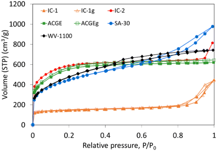 | ||
| Fig. 3 N2 adsorption–desorption isotherms at −196 °C for the carbon supports. | ||
The N2 adsorption isotherms of the SA-30 and WV-1100 activated carbons can be classified as a combination of type I and type IV. The high adsorption capacity at low relative pressures, and the slope and the hysteresis loop, evidence, respectively, the presence of a remarkable amount of micro and mesopores.39
The N2 adsorption isotherms for IC-1g and ACGEg samples are very similar to those of the parent samples, revealing that the milling process has a negligible effect on the textural properties determined by this method (Fig. 3). This can be well observed by the comparison of the pore size distribution of original and ground samples determined from N2 adsorption data (Fig. S1, ESI†).
In summary, the N2 adsorption–desorption isotherms shown in Fig. 3 reveal significant differences between the carbon materials in terms of pore volumes and pore size distributions.
Table 1 shows the specific surface area (SBET) and pore volumes calculated from N2 and CO2 adsorption data (CO2 adsorption isotherms not shown), and from Hg porosimetry, for the carbon materials. Analogous data for the supported catalysts (as prepared and reduced) are shown in Table S2.†
| Sample | S BET (m2 g−1) | V DR,CO2 (cm3 g−1) | V DR,N2 (cm3 g−1) | V meso,N2 (cm3 g−1) | V meso,Hg (cm3 g−1) | V T,meso (cm3 g−1) | V macro,Hg (cm3 g−1) |
|---|---|---|---|---|---|---|---|
| a Parameters calculated from the N2 adsorption isotherms as indicated in the text. b Parameters calculated from the CO2 adsorption isotherms as indicated in the text. c Parameters determined by Hg porosimetry. | |||||||
| IC-1 | 542 | 0.19 | 0.22 | 0.04 | 0.55 | 0.59 | 0.00 |
| IC-1g | 571 | 0.21 | 0.23 | 0.04 | 0.28 | 0.32 | 0.13 |
| IC-2 | 2081 | 0.60 | 0.92 | 0.07 | 0.04 | 0.12 | 1.17 |
| ACGE | 1920 | 0.50 | 0.81 | 0.09 | 0.29 | 0.38 | 0.01 |
| ACGEg | 1991 | 0.52 | 0.85 | 0.09 | 0.22 | 0.31 | 0.05 |
| SA-30 | 1587 | 0.35 | 0.68 | 0.31 | 0.40 | 0.71 | 0.41 |
| WV-1100 | 1713 | 0.37 | 0.70 | 0.30 | 0.51 | 0.81 | 0.20 |
Data of Table 1 show that all the carbon supports, except IC-1, present very high surface area and well-developed porosity. Despite their different origin (raw material and preparation method), IC-2 and ACGE show similarities in textural properties determined by N2 and CO2 adsorption, and they have the largest micropore volumes (particularly of narrow micropores (VDR,CO2)).
The SA-30 and WV-1100 carbons present large volume of mesopores and similar pore size distribution.
All the carbon materials, except IC-2, have a high Vmeso,Hg. The macropore volume is negligible for IC-1 and ACGE, moderate for SA-30 and WV-1100 (0.2 and 0.4 cm3 g−1, respectively), and very high for IC-2 (1.17 cm3 g−1). It can be mentioned that the volume of broad mesopores (Vmeso,Hg) is larger in IC-1g than in IC-1, and the first one contains some macropores.
The pore size distributions obtained by Hg porosimetry (Fig. S2, ESI† material), show that ACGE, SA-30, and WV-1100 present a wide pore size distribution, whereas for IC-1 and IC-2 it is practically mono- or bimodal. Thus, defined pores of about 24 nm, and between 20 and 160 nm, are present in IC-1 and in IC-2, respectively (in good agreement with the information provided by the manufacturer). These broad pores, usually defined as transport pores, can play a relevant role in the kinetics of liquid phase processes.
Data of Table S2† show that the specific surface areas of all the as-prepared supported catalysts (after impregnation with the RuCl3 aqueous solution and drying) are slightly lower than those of the corresponding carbon supports but, after the reduction treatment, the SBET values slightly increase again. Such behavior has previously been observed by other researchers.44
The N2 adsorption–desorption isotherms obtained for both, un-reduced and reduced catalysts, compared with those of the corresponding supports are presented in Fig. S3.† These data confirm that the metallic phase incorporation has a very slight effect on the textural properties of the resulting materials with respect to the supports.
The average pore size calculated from N2 adsorption data using the Quantachrome Quadrawin software (based on non-local-density functional theory (NLDFT), and based on the general adsorption isotherm (GAI) equation up to 0.7 relative pressure (ref. 45 and 46)), ranges from 2.0 to 4.5 nm (Table S3†).
To sum up, as the surface area and porosity of the catalysts (reduced and non-reduced) and the corresponding supports are very similar, it can be assumed that the incorporation of ruthenium only has a slight effect on the textural properties of the catalysts, being the pore size distribution preserved. The largest decrease in the support's surface area upon metal incorporation, around 14%, corresponds to sample IC-2. This agrees with the large volume of narrow micropores and small volume of mesopores of this carbon material.
TPD and titration of acid sites results
TPD measurements allow estimating the amount and type of oxygen surface groups on the carbon materials. As it is known, CO2 is mainly produced from the decomposition of functional groups such as carboxylic acids, anhydrides, and lactones, with acidic character, while CO emission is due to the decomposition of phenol type groups, weakly acidic, and of carbonyls and quinones, of basic character.47 A schematic representation of these surface oxygen groups is presented in Fig. S4, and Table S4† shows the reported decomposition temperature intervals.48,49The obtained TPD patterns reveal significant differences between the surface chemistry of the different carbon materials (Fig. 4 and Table 2). The following observations can be pointed out: the two granular commercial ACs (SA-30 and WV-1100) have a large and similar total content of oxygen groups. This content is moderate for ACGE and IC-1, and quite low for IC-2. Finally, milling produces a certain increase of the surface oxygen content in IC-1, and almost no modification in ACGE.
 | ||
| Fig. 4 TPD spectra of supports and reduced catalysts: evolution of (a) CO2 and (b) CO. (be aware of the different y-axis scale in figures (a) and (b)). | ||
| Sample | CO2 (μmol g−1) | CO (μmol g−1) | Ototal (wt%) | Acid sites (mmol g−1) |
|---|---|---|---|---|
| IC-1 | 258 | 928 | 2.3 | 0.82 |
| IC-1g | 374 | 1172 | 3.1 | — |
| IC-2 | 68 | 208 | 0.6 | 0.48 |
| ACGE | 351 | 1559 | 3.6 | 0.90 |
| ACGEg | 342 | 1267 | 3.1 | — |
| SA-30 | 539 | 2065 | 5.0 | 1.60 |
| WV-1100 | 735 | 2202 | 5.9 | 1.40 |
It should be mentioned that the decomposition of surface oxygen groups does not imply non-stability of the catalysts, since such process does not occur at the reaction temperature (70 °C).
Although TPD data of the Ru/C catalysts could have been considered suitable to extract information about the surface chemistry of the catalysts, metallic Ru exerts a catalytic effect on the decomposition of some surface oxygen functional groups31,50,51 and, thus, this affects the CO2 and CO evolution profiles (qualitative and quantitatively). Fig. S5 and Table S5† show, respectively, the comparison of the TPD profiles and of the corresponding quantification, for supports and reduced catalysts.
The acidity of the carbon supports has been measured by titration, what allows to quantify Brønsted acid groups (H+ donors), which are mainly carboxylic and phenol-type groups. The results, expressed as mmol of acid sites per gram of support (Table 2), show significant differences in the acidity of these carbon materials.
TPR results
The TPR analysis of the as-prepared catalysts is depicted in Fig. 5. As the decomposition of surface oxygen groups during the TPR test leads to some interferences in the TCD signal, the TPR data have only been plotted up to 300 °C (to focus on the reduction of Ru species, with minor effect of the surface oxygen groups decomposition). The complete profiles are shown in Fig. S6,† including the TPR and TPD profiles of the supports, to better observe the effect of the supported Ru. | ||
| Fig. 5 TPR profiles of the Ru/C samples. | ||
The TPR profiles of the as prepared catalysts show that: i) for Ru/IC-2 and Ru/ACGE, two defined maxima are observed, in both cases the first one at about 60 °C, and the second one at 110 °C for Ru/IC-2, and at 130 °C for Ru/ACGE. These peaks could be associated to the reduction of different Ru species,52–54 or to the reduction of the Ru species with different interaction with the surface of the carbon materials.55 Moreover, since Ru is reduced, a spill over effect is not discarded. This information agrees with the XPS results shown and discussed later. ii) For Ru/IC-1, there is only one wide peak, with the maximum at about 70 °C. This peak seems to include several processes, and indicates the presence of Ru species of different reducibility.52 iii) In the case of the Ru/WV-1100 and Ru/SA-30 catalysts, the Ru reduction is observed at higher temperatures (maximum reduction at about 160 and 150 °C, respectively), but it is a less defined process, probably because the metal reduction overlaps with the decomposition of surface oxygen functional groups56 (see Fig. S6†).
These data show that the reducibility of the Ru species is strongly influenced by the nature of the carbon material used as support. It should be pointed out that the behaviour of the catalysts prepared with the spherical carbon materials and with the granular or powdered activated carbons is significantly different.
The TPR profiles of the catalysts prepared with the ground and original supports are quite similar (Fig. S7†).
XPS analysis
The Ru 3p3/2 XPS profiles of the Ru/C catalysts (as-prepared and reduced) are presented in Fig. S8.† Spectra of the as-prepared catalysts show two peaks, at ∼463 eV, which can be assigned to RuClx, and at ∼465.5–466.5 eV, which corresponds to Ru–O species, represented as RuOx.57–60 The specific binding energies determined for each sample and the calculated proportion of the different proposed species are compiled in Table 3. According to these data, chloride species are present in a larger proportion than oxide ones.| Sample | RuClx | RuOx | Ru0 | RuOx/Ru0 | Oacida (wt%) | Cl (wt%) |
|---|---|---|---|---|---|---|
| a Calculated from O 1s XPS results, as sum of wt% of oxygen species corresponding to carboxylic and phenolic groups. | ||||||
| Ru/IC-1 | 463.36 (65%) | 466.18 (35%) | — | — | 5.28 | 1.67 |
| RuR/IC-1 | — | — | 461.85 (71%) | 465.25 (29%) | 3.88 | 0.57 |
| Ru/IC-2 | 463.07 (68%) | 465.47 (32%) | — | — | 3.71 | 1.13 |
| RuR/IC-2 | — | — | 462.04 (72%) | 464.86 (28%) | 3.20 | 0.76 |
| Ru/ACGE | 463.66 (79%) | 466.47 (21%) | — | — | 5.00 | 1.61 |
| RuR/ACGE | — | — | 462.06 (80%) | 464.87 (20%) | 7.91 | 0.54 |
| Ru/SA-30 | 463.23 (59%) | 466.18 (41%) | — | — | 7.72 | 0.74 |
| RuR/SA-30 | — | — | 461.70 (63%) | 464.42 (37%) | 7.65 | 0.14 |
| Ru/WV-1100 | 463.17 (76%) | 465.54 (24%) | — | — | 12.60 | 0.63 |
| RuR/WV-1100 | — | — | 462.36 (83%) | 465.42 (17%) | 9.42 | 0.80 |
In the case of the reduced catalysts, Ru is present in different oxidation states. The peak at about 462 eV reveals the presence of Ru0,61,62 while the peak at about 464.5–465 eV can be assigned to RuOx/Ru0 species (oxidized Ru on metallic Ru).60 This kind of species is probably the result of some surface oxidation of the reduced Ru nanoparticles. As shown in Table 3, in the RuR/C catalysts Ru is mainly in the reduced state.
As chloride is found on the reduced catalysts, but RuClx seems not to be present, it can be assumed that a small amount of chloride (199 eV (ref. 57 and 58)) remains interacting with the carbon surface.
The XPS analysis of the O 1s signal in the un-reduced and reduced catalysts (Fig. S9†) helps to evaluate their surface chemistry. Table S6† shows the quantification of the amount of oxygen present as carbonyl and anhydride (B.E. about 531 eV designated as O1), phenol (B.E. about 533 eV, designated as O2), and carboxylic (B.E. about 534 eV, designated as O3)37,63–65 groups in each sample (these assignations of peaks to O species is also indicated in Fig. S9†). It should be pointed out that oxygen bonded to Ru cannot be distinguished because of the low amount of Ru–O species with respect to the abundant surface oxygen complexes. In particular the signal of oxygen bonded to Ru (in RuOx species, with B.E. around 530 eV (ref. 66)) would appear at similar B.E. as the one due to O1 one, which makes even more difficult to distinguish these species.
(The survey XPS data and the elemental surface composition (at%) of the analysed samples are shown in Fig. S10 and Table S7,† respectively).
As the amount of oxygen associated with carboxylic-type and phenol-type surface oxygen groups can be used as a tentative evaluation of the acidity of the Ru/C and RuR/C samples, the sum of O wt% corresponding to O2 and O3 species has been calculated, identified as Oacid (wt%), and included in Table 3. These data reveal that the catalysts' acidity trend, determined this way, is similar to the one found by the supports' titration. Also, these data show that the acidity is lower in the reduced catalysts than in the un-reduced (as prepared) ones, in agreement with the removal of the less thermally-stable oxygen surface groups (mainly carboxylic acid type) as a consequence of the reduction heat treatment.
Morphology of supports and distribution of Ru particles
Fig. S11† shows the FESEM images obtained for the carbon materials used as supports in this work. They clearly reveal the important differences in the surface morphology of spherical and granular carbons. The spherical carbons, IC-1 and IC-2, show a relatively smooth surface with some “openings” that can be related to large pores. These openings are noticeably more abundant and larger in the case of carbon IC-2, allowing to distinguish an inner structure made of particle aggregates (see detail in Fig. S11b2†). According to the manufacturer, the porous structure of these carbon materials is typical of xerogel materials, with irregular form and interparticle porosity (very different from the slit or channel porous structures of granular or powdered activated carbons). ACGE also shows a smooth surface with some “holes”, which are smaller than in IC-1 and IC-2. In the case of SA-30 and WV-1100, a wrinkled and irregular surface is observed, and the morphology and size of the discernible wide porosity (interparticular spaces or cavities) is very heterogeneous (images d2 and e2, in Fig. S11†), with irregular form and interparticle porosity.Fig. 6 shows some representative TEM images of as-prepared (un-reduced) and reduced catalysts.
 | ||
| Fig. 6 TEM images of un-reduced and reduced catalysts and EDX of reduced catalysts: Ru/IC-1 (a1), RuR/IC-1 (a2 and a2x), Ru/IC-2 (b1), RuR/IC-2 (b2 and b2x), Ru/ACGE (c1), RuR/ACGE (c2 and c2x), Ru/SA-30 (d1), RuR/SA-30 (d2 and d2x), RuR/WV-1100 (e1) and RuR/WV-1100 (e2 and e2x). Images have been obtained with the TALOS F200X Microscope coupled to an EDX system. | ||
Images a1–e1, which correspond to the un-reduced catalysts, show some dark areas due to overlapping layers of carbon. Ru nanoparticles are not observed, and a higher resolution would be required to detect other Ru species (i.e., atomically distributed ones).
In the case of the reduced catalysts (TEM images a2–e2 and EDX mapping in images a2x–e2x) Ru nanoparticles can be observed, although they are very small and cannot always be distinguished from the carbon support. With the only exception of RuR/ACGE, the reduced catalysts show a good particle size distribution, and mean particle sizes ranging from about 2 to 4 nm (Fig. 6 and Table 4, respectively). The particle size distribution in RuR/ACGE is wider (1–60 nm), the mean particle size is close to 15 nm, but there are many small Ru nanoparticles. The obtained data show that, in general, the catalysts present a good metal dispersion and a good distribution of metal particles (Fig. S12†).
| Catalyst | Mean Ru particle size (nm) |
|---|---|
| RuR/IC-1 | 3.45 ± 4.16 |
| RuR/IC-2 | 3.31 ± 4.18 |
| RuR/ACGE | 14.84 ± 14.05 |
| RuR/SA-30 | 2.90 ± 3.55 |
| RuR/WV-1100 | 2.19 ± 0.54 |
Catalytic activity results
Results of the blank experiments (without catalyst and with the carbon supports) have shown that LA conversion does not occur in the absence of Ru. Moreover, some LA adsorption on the IC-2 carbon has been observed (about 7% of LA is adsorbed), which can be related to the large transport pores (with size around 160 nm) of this support.The catalytic activity results obtained for the RuR/C catalysts are presented in Table 5. It should be pointed out that all the reduced catalysts lead to a high LA conversion (∼80–90%) and high selectivity to GVL (70–86%) at the moderate reaction temperature used in the catalytic tests. In all cases, hydroxypentanoic acid (HPA) was detected as the only by-product.
| Entry | Catalyst | LA conversion (%) | GVL yield (%) | GVL selectivity (%) | HPA selectivity (%) |
|---|---|---|---|---|---|
| 1 | RuR/IC-1 | 78 | 63 | 82 | 18 |
| 2 | RuR/IC-2 | 81 | 69 | 86 | 14 |
| 3 | RuR/ACGE | 81 | 59 | 73 | 27 |
| 4 | RuR/SA-30 | 88 | 62 | 70 | 30 |
| 5 | RuR/WV-1100 | 94 | 75 | 80 | 20 |
The differences between the catalytic performance of these catalysts are relatively small and, thus, it can be concluded that the Ru nanoparticles are almost equally active in all of them, and their performance is not influenced by the different properties of the supports. It can be assumed that the reduction treatment (H2 (75 mL min−1) 250 °C, 4 h) generates Ru nanoparticles of the suitable size and structure to carry out the LA hydrogenation efficiently. It can be highlighted that the catalysts prepared with the spherical supports lead to quite satisfactory results, with the added advantage respect to the powdery catalysts of a significantly easier manipulation.
As this research work aimed to make simpler and less expensive catalytic systems (from the point of view of the catalysts preparation procedures and conditions and the catalytic activity tests), the possibility of skipping the reduction treatment, usually performed prior to the use of the catalysts, has been investigated.
Table 6 shows the catalytic activity results obtained with the as-prepared (un-reduced) catalysts.
| Entry | Catalyst | LA conversion (%) | GVL yield (%) | GVL selectivity (%) | HPA selectivity (%) |
|---|---|---|---|---|---|
| a Not determined because of the negligible HPLC signal. | |||||
| 1 | Ru/IC-1 | 63 | 56 | 90 | 10 |
| 2 | Ru/IC-1g | 74 | 59 | 79 | 21 |
| 3 | Ru/IC-2 | 84 | 63 | 76 | 24 |
| 4 | Ru/ACGE | 68 | 58 | 86 | 14 |
| 5 | Ru/ACGEg | 64 | 42 | 66 | 34 |
| 6 | Ru/SA-30 | 13 | 5 | 40 | —a |
| 7 | Ru/WV-1100 | 11 | 4 | 40 | —a |
The un-reduced catalysts show very different catalytic activity depending on the support's nature. The catalysts prepared with the spherical carbon materials (IC-1, IC-2 and ACGE), which contain a low-to-moderate amount of surface oxygen groups, are noticeably more active than those prepared with the granular or powder activated carbons, being almost as active as their reduced counterparts. This constitutes an important advantage because H2 and energy consumption are avoided, and a time-consuming step can be omitted. These results imply that total or partial in situ Ru reduction may occur in these samples during the catalytic tests. In contrast, the granular Ru/WV-1100 and powder Ru/SA-30 catalysts, present a very low LA conversion and extremely low GVL yield, which allows to assume that in them, the reduction process is less efficient. In these last two cases, as the LA conversion is very low, the amount of HPA is negligible and the low signal does not allow a proper quantification.
In situ (under reaction conditions) reduction process has been also found to occur in other studies. For example, Zhang et al.67 found that in the CuAg/Al2O3 catalysts used in the hydrogenation of LA to GVL (180 °C, 1.4 bar H2, 4 h) CuO was reduced assisted by the spill-over effect caused by Ag. In the recent work of Chaparro-Garnica et al.,68 Pd was supported on carbon materials functionalized with nitrogen and they were used to obtain hydrogen by formic acid dehydrogenation. These catalysts were used either after reduction with NaBH4 or un-reduced, and it was found that the un-reduced catalysts performed better, which was explained by a more effective in situ (under reaction conditions) reduction of the catalysts by the generated hydrogen.
The stability and reusability of the un-reduced catalysts have been studied by performing several consecutive catalytic runs with Ru/IC-1, Ru/IC-2, and Ru/WV-1100. The results are presented in Table 7. It can be observed that Ru/IC-1 maintains the activity after four consecutive catalytic runs. This implies that the Ru species become reduced (at least partially) in the first catalytic run, and the Ru/IC-1 catalyst is very stable. Ru/IC-2 maintains a high LA conversion in the second catalytic run, but the selectivity to GVL decreases about 50%. Finally, the catalytic activity of Ru/WV-1100 increases from run to run, and in the third run, LA conversion and GVL selectivity are as high as for Ru/IC-1. It seems that successive catalytic runs lead to a high reduction of the Ru species (and could also produce some sintering of the Ru particles). As LA conversion is kept (or increased) in consecutive runs, it can be assumed that metal leaching is negligible.
| Catalyst | LA conversion (%) | GVL yield (%) | GVL selectivity (%) |
|---|---|---|---|
| R1 Ru/IC-1 | 63 | 56 | 90 |
| R2 Ru/IC-1 | 67 | 49 | 73 |
| R3 Ru/IC-1 | 57 | 51 | 89 |
| R4 Ru/IC-1 | 72 | 61 | 85 |
| R1 Ru/IC-2 | 84 | 63 | 76 |
| R2 Ru/IC-2 | 89 | 29 | 33 |
| R1 Ru/WV-1100 | 11 | 4 | 40 |
| R2 Ru/WV-1100 | 36 | 32 | 90 |
| R3 Ru/WV-1100 | 68 | 65 | 96 |
To analyse in depth the effect of the spherical morphology of the supports, Ru catalysts prepared with the IC-1g and ACGEg milled carbons have been also tested. The obtained results, included in Table 6, show that the catalytic properties do not change when the ground supports are used. This allows to rule out a particular effect of the morphology.
Characterization of used catalysts
As the catalysts become (at least partially) reduced in situ under reaction conditions, the characterization of the used samples was performed to better understand the observed catalytic behaviour. The XPS analysis of the used Ru/IC-1 and Ru/SA-30 catalysts reveals that both contain Ru0 but in quite different proportions: 61% and 21%, respectively, confirming that the in situ reduction process occurs to a larger extent in the case of the first one.Fig. 7 shows a comparison of the Ru 3p3/2 XPS patterns obtained for RuR/C and used Ru/C catalysts (prepared with IC-1 and SA-30 supports). Apart from the important modification of the electronic state of Ru upon use, a slight displacement of the Ru0 B.E. towards higher values is observed for the two of them. This indicates that the interaction of the in situ reduced Ru species is different (likely stronger or more extensive) than for those reduced with H2 at 250 °C.69
 | ||
| Fig. 7 XPS results for (a) RuR/IC-1 (continuous line) and Ru/IC-1 (dotted line), and (b) RuR/SA-30 (continuous line) and Ru/SA-30 (dotted line). Signals in orange and blue correspond to RuOx and Ru(0), respectively. | ||
The more efficient reduction under reaction conditions of Ru/IC-1, Ru/IC-2, and Ru/ACGE catalysts agrees with the lower temperature reduction features determined for them in the TPR measurements (Fig. 5).
TEM-EDX analysis of the spent RuR/C catalysts shows that they present well distributed and small Ru particles (2–4 nm average size) similar to those found in the fresh RuR/C catalysts (Fig. S12†) (compare images a2–e2 of Fig. 6, with the corresponding images a2–e2 (i, ii and iii) in Fig. S13†). This means that the mild reaction conditions do not produce any sintering of the original Ru nanoparticles. The Ru/C spent catalysts also show metallic Ru nanoparticles (compare images a1–e1 of Fig. 6 with the corresponding images a1–e1 (i, ii and iii) in Fig. S13†), in line with XPS data, confirming the in situ reduction process.
The mean particle size in used Ru/IC-1 and Ru/ACGE catalysts is 2.4 and 2.3 nm respectively, which is similar to the one obtained for the previously reduced samples. In contrast, for the used Ru/SA-30 and Ru/WV-1100 catalysts, very small Ru particles have been detected (smaller than 1 nm, although a proper statistic size analysis has been difficult, see images d1 and e1 in Fig. S13†), noticeably lower than those observed after the external H2 reduction treatment at 250 °C. Thus, the in situ reduction process reveals significant differences in the interaction of Ru species with the surface of IC-1, IC-2, and ACGE on one side, and of SA-30 and WV-1100 on the other side. A tentative explanation of this difference is the following: the Ru species present in the solution used to impregnate the supports are prone to be anchored on surface oxygen groups and, as the amount of surface oxygen groups in the commercial activated carbons is larger than in the spherically shaped carbon materials, such an anchorage is favoured in the first ones (being feasible an atomic dispersion). The mapping images presented in Fig. S14† corresponding to catalyst Ru/WV-1100 show that O and Ru appear in the same areas. The reduction treatment at 250 °C produces the decomposition of the less thermally stable surface oxygen groups, with the consequent mobility of the anchored Ru species (leading to Ru nanoparticles of size around 2–4 nm). In contrast, in the in situ (under reaction conditions, 70 °C) reduction, such a decomposition of surface oxygen groups is limited, and the reduced particles remain smaller. In other words, for the carbon materials with larger amount of surface oxygen groups, the low temperature reduction process leads to very small (and less reducible) Ru particles, due to the original high dispersion of the Ru species anchored on the rich oxygen groups surface.
It should be mentioned that the XPS and TEM analysis have allowed to indirectly state that the Ru content on the catalysts has not appreciably decreased upon use. Besides, the results of the reuse experiments do not reveal the loss of active species from the catalysts. All these pieces of evidence the catalysts' stability.
Final remarks
The results presented above indicate that the in situ (under reaction conditions) reduction of catalysts prepared with the supports that contain less surface oxygen groups is more effective, and the nanoparticles developed are bigger (of about 2–4 nm). These two facts are behind the higher catalytic activity of the as-prepared Ru/IC-1, Ru/IC-2, and Ru/ACGE catalysts compared to Ru/SA-30 and Ru/WV-1100 ones. This effect of the particle size is in line with other studies dealing with hydrogenation reactions which report lower catalytic activity when the active phase is present as single atoms.70,71Although an effect of the porous structure (pores shapes, tortuosity, etc.) cannot be discarded, the surface chemistry has shown to have the highest influence.
The present study has shown that the prepared catalysts are quite efficient for the transformation of LA into GVL under mild reaction conditions. The excellent results obtained with catalysts for which the thermal reduction with H2 can be skipped if the appropriate carbon supports are used is of particular importance.
For a better evaluation of the relevance of the obtained activity results, it is interesting to compare them with previously published data dealing with carbon-supported Ru catalysts for the same reaction, also carried out in aqueous media (Table 8).
| Entry | Catalyst | Nominal Ru wt% | Reduction prior to catalytic use/conditions | S/Ca | T (°C) | P (bar) | t (min) | GVL yield (%) | r s (h−1) | Ref. |
|---|---|---|---|---|---|---|---|---|---|---|
| a Substrate/catalyst ratio (initial LA moles/Ru moles in the catalyst). b Non-specified flow rate. c NaBH4/RuCl3 molar ratio = 2.5. d All the reduced catalysts presented in this work. | ||||||||||
| 1 | Ru/C | 5 | YES/500 °C, 1 h, H2b | 58 | 190 | 10 | 60 | 64–83 | 44–55 | 25 |
| 2 | Ru/C-DARCO | 5 | YES/200 °C, 1 h, H2b | 58 | 190 | 10 | 60 | 72 | 50 | 26 |
| 3 | Ru/C Vulcan XC72R | 1 | YES/NaBH4c | 155 | 100 | 5 | 60 | 80 | 155 | 54 |
| 4 | Ru/C | 0.5 | YES/450 °C, 4 h, H2b | 46 | 90 | 45 | 360 | 72 | 24 | 72 |
| 5 | RuR/Cd | 1 | 250 °C, 4 h, H2 (75 ml min−1) | 338 | 70 | 15 | 60 | 59–75 | 274–318 | This work |
| 6 | Ru/IC-2 | 1 | NO | 338 | 70 | 15 | 60 | 63 | 306 | This work |
| 7 | Ru/IC-1 | 1 | NO | 338 | 70 | 15 | 60 | 56 | 213 | This work |
The work of Jędrzejczyk et al.25 (entry 1) is focused on the nature of the carbon material used as support for Ru/C catalysts. Several types of commercially available carbon materials were used by these researchers: AC with different grain size (<0.1–1 mm) by Windsor Laboratories, Ltd. (UK); Norit carbon (grain size < 0.1 mm) by ChemPur, Piekary Slaskie (Poland) and AG carbon (grain size < 0.1 mm) delivered by Gryfskand, Gryfino (Poland). The study reports that the most active catalysts (83% GVL yield) are those in which the support has the largest number of defects because they lead to a strong metal–support interaction. The work of Ruppert et al.26 (entry 2) studies the effect of the Ru precursor (RuCl3 or Ru(acac)3) and of the reduction temperature, in catalysts prepared with the commercial activated carbon C-DARCO. A high GVL yield (72%) was obtained using the RuCl3 and the lowest reduction T (200 °C).
The recent work of Jones et al.54 (entry 3) uses NaBH4 to reduce the catalysts during the catalyst preparation procedure, and the GVL yield obtained is high (80%). In these last two studies, the specific velocity is lower than in the present work because of the higher Ru loading (5 wt%). On the other hand, Piskun et al.72 (entry 4) using a commercial 0.5 wt% Ru/C (Johnson Matthey) and a relatively low temperature but high pressure (90 °C and 45 bar H2) obtained a good GVL yield (72%) but in 6 h reaction time.
The comparison of the results of this work (entries 5, 6, and 7) with those obtained by other researchers shows that high GVL yields and very high specific reaction rates (rs) are obtained with the catalysts prepared in this work. It is particularly interesting that very good results have been obtained under mild reaction conditions and with catalysts that had not been previously reduced (entries 6 and 7). This implies the saving of energy hydrogen, and time. Also, the proportion of metal used in the present study is lower than in other works (higher relation S/C). In summary, it can be considered that the developed catalysts and the stated reaction conditions make the studied catalytic system quite interesting from the point of view of easy management and energy saving.
Conclusions
Ru/C catalysts for the transformation of levulinic acid (LA) to gamma-valerolactone (GVL) have been prepared using as supports carbon materials, which differ in porous texture, surface chemistry, and morphology. The reaction has been carried out at 70 °C, a relatively low temperature compared with other reported works, in order to make the process less energy-demanding. All the RuR/C catalysts (reduced in H2 at 250 °C) provide very good LA conversion and GVL yield (60–70%), meaning that the reduction treatment leads to very active catalytic species in all catalysts, independently of the differences between supports. Skipping the pre-reduction process has shown that using the un-reduced catalysts, the catalytic properties strongly depend on the supports' properties. The most active and selective (un-reduced) catalysts are those prepared with supports that contain lower amount of surface oxygen groups.The surface chemistry has shown to be behind the effectiveness of the in situ reduction and of the development of Ru nanoparticles of the suitable size (of about 2–4 nm, instead of very small ones). In contrast, the support's morphology per se does not seem to be determinant.
However, the used spherically shaped supports meet interesting properties, as they have led to catalysts that are not only active and reusable catalysts without the costly pre-reduction treatment but also more easily handled.
The corollary of this work is that carbon materials offer many possibilities to develop active, selective, and practical catalysts. In this application, the carbon surface chemistry has revealed to be crucial for a suitable support–metal interaction that determines the reducibility of the Ru species (conventional thermal reduction can be skipped) as well as the size of the developed particles, leading to active, selective and stable catalysts for this application.
Author contributions
Z. R.-B.: conceptualization, methodology, investigation, data curation, formal analysis, writing – original draft, writing – review & editing. M. A. L.-R. and M. C. R.-M.: conceptualization, methodology supervision, formal analysis, writing – review & editing, funding acquisition, project administration.Conflicts of interest
There are no conflicts to declare.Acknowledgements
This work was supported by the following research projects: RTI2018–095291-B-100 and PID2021–123079OB-I00 (project funded by MICINN/AEI/10.13039/501100011033 and by ERDF A way of making Europe (European Union)), CIPROM/2021/070 (Generalitat Valenciana) and VIGROB-136 (University of Alicante). Z. R.-B. thanks MICINN for the pre-doctoral scholarship (PRE2019-090049). The authors thank Immutrix Therapeutics and Ingevitiy Corporation (both in the USA) for providing carbon materials. The research technical services of the University of Alicante and the University of Cádiz (both in Spain) are also acknowledged.References
- L. T. Mika, E. Cséfalvay and Á. Németh, Chem. Rev., 2018, 118, 505–613 CrossRef CAS PubMed.
- Z. Jiang, D. Hu, Z. Zhao, Z. Yi, Z. Chen and K. Yan, Processes, 2021, 9, 1234 CrossRef CAS.
- S. Kang, J. Fu and G. Zhang, Renewable Sustainable Energy Rev., 2018, 94, 340–362 CrossRef CAS.
- D. M. Alonso, S. G. Wettstein and J. A. Dumesic, Green Chem., 2013, 15, 584 RSC.
- R. Weingarten, W. C. Conner and G. W. Huber, Energy Environ. Sci., 2012, 5, 7559–7574 RSC.
- H. F. Liu, F. X. Zeng, L. Deng, B. Liao, H. Pang and Q. X. Guo, Green Chem., 2013, 15, 81–84 RSC.
- K. Yan, C. Jarvis, J. Gu and Y. Yan, Renewable Sustainable Energy Rev., 2015, 51, 986–997 CrossRef CAS.
- Y. Shen, J. Sun, B. Wang, F. Xu and R. Sun, BioResources, 2014, 9, 3264–3275 Search PubMed.
- S. Dutta, I. K. M. Yu, D. C. W. Tsang, Y. H. Ng, Y. S. Ok, J. Sherwood and J. H. Clark, Chem. Eng. J., 2019, 372, 992–1006 CrossRef CAS.
- Á. Bereczky, K. Lukács, M. Farkas and S. Dóbé, Nat. Resour. Res., 2014, 5, 177–191 Search PubMed.
- I. T. Horváth, H. Mehdi, V. Fábos, L. Boda and L. T. Mika, Green Chem., 2008, 10, 238–242 RSC.
- X. Tang, X. Zeng, Z. Li, L. Hu, Y. Sun, S. Liu, T. Lei and L. Lin, Renewable Sustainable Energy Rev., 2014, 40, 608–620 CrossRef CAS.
- K. Hengst, M. Schubert, H. W. P. Carvalho, C. Lu, W. Kleist and J. D. Grunwaldt, Appl. Catal., A, 2015, 502, 18–26 CrossRef CAS.
- W. Luo, U. Deka, A. M. Beale, E. R. H. van Eck, P. C. A. Bruijnincx and B. M. Weckhuysen, J. Catal., 2013, 301, 175–186 CrossRef CAS.
- W. R. H. Wright and R. Palkovits, ChemSusChem, 2012, 5, 1657–1667 CrossRef CAS PubMed.
- A. M. R. Galletti, C. Antonetti, V. De Luise and M. Martinelli, Green Chem., 2012, 14, 688–694 RSC.
- E. F. Mai, M. A. Machado, T. E. Davies, J. A. Lopez-Sanchez and V. T. da Silva, Green Chem., 2014, 16, 4092–4097 RSC.
- J. P. Lange, R. Price, P. M. Ayoub, J. Louis, L. Petrus, L. Clarke and H. Gosselink, Angew. Chem., Int. Ed., 2010, 49, 4479–4483 CrossRef CAS.
- J. C. Serrano-Ruiz, D. Wang and J. A. Dumesic, Green Chem., 2010, 12, 574–577 RSC.
- V. V. Kumar, G. Naresh, M. Sudhakar, C. Anjaneyulu, S. K. Bhargava, J. Tardio, V. K. Reddy, A. H. Padmasri and A. Venugopal, RSC Adv., 2016, 6, 9872–9879 RSC.
- Z. P. Yan, L. Lin and S. Liu, Energy Fuels, 2009, 23, 3853–3858 CrossRef CAS.
- O. A. Abdelrahman, A. Heyden and J. Q. Bond, ACS Catal., 2014, 4, 1171–1181 CrossRef CAS.
- A. Hommes, A. J. ter Horst, M. Koeslag, H. J. Heeres and J. Yue, Chem. Eng. J., 2020, 399, 125750 CrossRef CAS.
- L. E. Manzer, Appl. Catal., A, 2004, 272, 249–256 CrossRef CAS.
- M. Jędrzejczyk, E. Soszka, J. Goscianska, M. Kozanecki, J. Grams and A. M. Ruppert, Molecules, 2020, 25, 5362 CrossRef PubMed.
- A. M. Ruppert, M. Jędrzejczyk, O. Sneka-Płatek, N. Keller, A. S. Dumon, C. Michel, P. Sautet and J. Grams, Green Chem., 2016, 18, 2014–2028 RSC.
- M. Wu, J. Liao, L. Yu, R. Lv, P. Li, W. Sun, R. Tan, X. Duan, L. Zhang, F. Li, J. Kim, K. H. Shin, H. S. Park, W. Zhang, Z. Guo, H. Wang, Y. Tang, G. Gorgolis, C. Galiotis and J. Ma, Chem. - Asian J., 2020, 15, 995–1013 CrossRef CAS.
- H. Marsh and F. Rodríguez-Reinoso, in Activated carbon, 2006, pp. 13–86 Search PubMed.
- D. Zhang, Y. P. Zhao, X. Fan, Z. Q. Liu, R. Y. Wang and X. Y. Wei, Catal. Surv. Asia, 2018, 22, 129–135 CrossRef CAS.
- Q. Xu, X. Li, T. Pan, C. Yu, J. Deng, Q. Guo and Y. Fu, Green Chem., 2016, 18, 1287–1294 RSC.
- Z. Ruiz-Bernal, M. Á. Lillo-Ródenas and M. del C. Román-Martínez, Catalysts, 2021, 11, 559 CrossRef CAS.
- F. Rodriguez-Reinoso, The Role of Carbon Materials in Heterogeneous Catalysis, 1998, vol. 36 Search PubMed.
- H. Zhu, W. Han and H. Liu, Catal. Lett., 2007, 115, 13–18 CrossRef CAS.
- C. Zanutelo, R. Landers, W. A. Carvalho and A. J. G. Cobo, Appl. Catal., A, 2011, 409, 174–180 CrossRef.
- Immutrix Therapeutics, INC., WO2019/126367, 2019, p. 32.
- M. Thommes, K. Kaneko, A. V. Neimark, J. P. Olivier, F. Rodriguez-Reinoso, J. Rouquerol and K. S. W. Sing, Pure Appl. Chem., 2015, 87, 1051–1069 CrossRef CAS.
- D. Cazorla-Amorós, J. Alcañiz-Monge and A. Linares-Solano, Langmuir, 1996, 12, 2820–2824 CrossRef.
- S. Lowell, J. E. Shields, M. A. Thomas and M. Thommes, Characterization of Porous Solids and Powders: Surface Area, Pore Size and Density, Springer Netherlands, Dordrecht, 2004, vol. 16 Search PubMed.
- M. Thommes, K. Kaneko, A. V. Neimark, J. P. Olivier, F. Rodriguez-Reinoso, J. Rouquerol and K. S. W. Sing, Pure Appl. Chem., 2015, 87, 1051–1069 CrossRef CAS.
- B. D. Zdravkov, J. J. Čermák, M. Šefara and J. Janků, Cent. Eur. J. Chem., 2007, 5, 385–395 CAS.
- A. L.-S. D. Cazorla-Amorós, J. Alcañiz-Monge and M. A. de la Casa-Lillo, Langmuir, 1998, 14, 4589–4596 CrossRef.
- C. Xiao, T. W. Goh, Z. Qi, S. Goes, K. Brashler, C. Perez and W. Huang, ACS Catal., 2016, 6, 593–599 CrossRef CAS.
- B. Folkesson, M. Bjorøy, J. Pappas, S. Skaarup, R. Aaltonen and C.-G. Swahn, Acta Chem. Scand., 1973, 27, 287–302 CrossRef CAS.
- F. Su, L. Lv, Y. L. Fang, T. Liu, A. I. Cooper and S. Z. Xiu, J. Am. Chem. Soc., 2007, 129, 14213–14223 CrossRef CAS PubMed.
- G. Kupgan, T. P. Liyana-Arachchi and C. M. Colina, Langmuir, 2017, 33, 11138–11145 CrossRef CAS PubMed.
- B. McEnaney and T. J. Mays, in Studies in Surface Science and Catalysis, 1988, vol. 39, pp. 151–161 Search PubMed.
- H. Boehm, Carbon, 2002, 40, 145–149 CrossRef CAS.
- J. Figueiredo, M. F. Pereira, M. M. Freitas and J. J. Órfão, Carbon, 1999, 37, 1379–1389 CrossRef CAS.
- G. S. Szymański, Z. Karpiński, S. Biniak and A. Świątkowski, Carbon, 2002, 40, 2627–2639 CrossRef.
- G. Peng, F. Gramm, C. Ludwig and F. Vogel, Catal. Sci. Technol., 2015, 5, 3658–3666 RSC.
- M. E. Grigorev, S. P. Mikhailov, A. V. Bykov, I. Y. Tiamina, L. Z. Nikoshvili, M. G. Sulman, A. L. Vasiliev, A. I. Sidorov, T. V. dos Santos, M. R. Meneghetti, S. M. P. Meneghetti, L. M. Bronstein and V. G. Matveeva, Colloids Surf., A, 2021, 610, 125722 CrossRef CAS.
- I. Rossetti, N. Pernicone and L. Forni, Appl. Catal., A, 2003, 248, 97–103 CrossRef CAS.
- A. M. Hengne, N. S. Biradar and C. V. Rode, Catal. Lett., 2012, 142, 779–787 CrossRef CAS.
- D. R. Jones, S. Iqbal, P. J. Miedziak, D. J. Morgan, J. K. Edwards, Q. He and G. J. Hutchings, Top. Catal., 2018, 61, 833–843 CrossRef CAS.
- S. Rio, G. Peru, B. Léger, F. Kerdi, M. Besson, C. Pinel, E. Monflier and A. Ponchel, J. Catal., 2020, 383, 343–356 CrossRef CAS.
- M. C. Román-Martínez, D. Cazorla-Amorós, A. Linares-Solano and C. S. M. de Lecea, Carbon, 1993, 31, 895–902 CrossRef.
- M. M. T. Khan and S. Srivastava, Polyhedron, 1988, 7, 1063–1065 CrossRef CAS.
- X. Wang, G. Lan, H. Liu, Y. Zhu and Y. Li, Catal. Sci. Technol., 2018, 8, 6143–6149 RSC.
- M. Adsuar-García, J. Flores-Lasluisa, F. Azar and M. Román-Martínez, Catalysts, 2018, 8, 572 CrossRef.
- J. Y. Shen, A. Adnot and S. Kaliaguine, Appl. Surf. Sci., 1991, 51, 47–60 CrossRef CAS.
- R. M. Mironenko, O. B. Belskaya, T. I. Gulyaeva, M. V. Trenikhin, A. I. Nizovskii, A. V. Kalinkin, V. I. Bukhtiyarov, A. V. Lavrenov and V. A. Likholobov, Catal. Today, 2017, 279, 2–9 CrossRef CAS.
- V. Mohan, V. Venkateshwarlu, C. V. Pramod, B. D. Raju and K. S. R. Rao, Catal. Sci. Technol., 2014, 4, 1253–1259 RSC.
- S. Kundu, Y. Wang, W. Xia and M. Muhler, J. Phys. Chem. C, 2008, 112, 16869–16878 CrossRef CAS.
- F.-Z. Azar, M. A. Lillo-Ródenas and M. C. Román-Martínez, SN Appl. Sci., 2019, 1, 1739 CrossRef CAS.
- National Institute of Standards and Technology, https://www.nist.gov/.
- K.-H. Kwak, D. W. Kim, Y. Kang and J. Suk, J. Mater. Chem. A, 2016, 4, 16356–16367 RSC.
- L. Zhang, J. Mao, S. Li, J. Yin, X. Sun, X. Guo, C. Song and J. Zhou, Appl. Catal., B, 2018, 232, 1–10 CrossRef CAS.
- J. Chaparro-Garnica, M. Navlani-García, D. Salinas-Torres, E. Morallón and D. Cazorla-Amorós, ACS Sustainable Chem. Eng., 2020, 8, 15030–15043 CrossRef CAS.
- C. S. Srikanth, V. P. Kumar, B. Viswanadham, A. Srikanth and K. V. R. Chary, J. Nanosci. Nanotechnol., 2015, 15, 5403–5409 CrossRef CAS PubMed.
- L. Luza, C. P. Rambor, A. Gual, J. A. Fernandes, D. Eberhardt and J. Dupont, ACS Catal., 2017, 7, 2791–2799 CrossRef CAS.
- Y. Zhang, D. T. Tran, D. Baker, S. Zhang, T. Wang, S. Hwang, E. Schulman, J. Fu, W. Zheng, D. G. Vlachos, J. Qi, P. Christopher, Y. Liu, A. Frenkel and D. Liu, Mol. Catal., 2022, 531, 112709 CrossRef CAS.
- A. S. Piskun, J. E. De Haan, E. Wilbers, H. H. Van De Bovenkamp, Z. Tang and H. J. Heeres, ACS Sustainable Chem. Eng., 2016, 4, 2939–2950 CrossRef CAS.
Footnote |
| † Electronic supplementary information (ESI) available. See DOI: https://doi.org/10.1039/d3re00497j |
| This journal is © The Royal Society of Chemistry 2024 |