Preparing Ti3C2-modified ZnFe2O4 photocatalytic materials and evaluating their performance in degrading tetracycline in water†
Received
7th July 2023
, Accepted 25th September 2023
First published on 28th September 2023
Abstract
To address the increasingly severe problem of water pollution, investigating novel, highly efficient, water treatment materials has become the current research hotspot. Herein, metal–oxygen-rich Ti3C2-modified ZnFe2O4 photocatalytic materials have been designed under alkaline conditions using the solvothermal method to achieve high-efficiency degradation of tetracycline hydrochloride (TCH) in water. Experimental results reveal that Ti3C2/ZnFe2O4 couples well and exhibits excellent optoelectronic and carrier-separating properties. Under visible light, 0.25/1 Ti3C2/ZnFe2O4 exhibited the best photocatalytic performance with a TCH removal efficiency of 87.10%; its reaction rate was 2.0 and 35.2 times higher than those of ZnFe2O4 and Ti3C2, respectively. Using the electron spin resonance technique, ·O2−, ·OH and h+ were determined to be the active substances involved in the photocatalytic degradation of TCH; on this basis, a reaction mechanism was proposed. The intermediates of TCH generated during photocatalytic degradation were identified using high-performance liquid chromatography–mass spectrometry, and possible degradation pathways were analysed. In addition, the potential toxicity of the intermediates in the environment was calculated and analysed using Ecological Structure Activity Relationships (ECOSAR) simulations, and the responsiveness of the photocatalytic materials to other pollutants in water was assessed in terms of universality. Experimental results reveal that Ti3C2 and ZnFe2O4 coupled photocatalytic materials exhibit excellent performance when degrading TCH, as well as high environmental friendliness, broadening their potential application in the field of water environment remediation.
1. Introduction
Antibiotics are widely used in human, animal and plant medicines. Among them, broad-spectrum, highly effective tetracycline hydrochloride (TCH) has received considerable attention; however, despite its positive effects, its resistance to degradation in the natural environment can cause considerable accumulation in aquatic settings, posing a serious threat to human health and ecosystems.1–3 In recent years, technologies such as adsorption, flocculation and biochemical treatment have been used to treat TCH in the environment; however, their application has been limited by long cycle times, incomplete degradation, high costs and the tendency to cause secondary pollution of the aquatic environment. Therefore, there is an urgent need to develop an efficient and environmentally friendly strategy for the removal of TCH compared to the existing pollutant treatment methods.4 Photocatalysis is a safe, efficient, economical and environmentally friendly method whose sustainable use has aroused widespread interest among researchers.5
In recent years, zinc ferrate (ZnFe2O4), a spinel oxide with a tunable bandgap (1.9–2.1 eV), has been demonstrated to be an excellent photocatalyst.6 As an n-type semiconductor, ZnFe2O4 contains Zn in tetracoordination and Fe in hexacoordination, occupying the tetrahedral and octahedral gaps, respectively, in O2-dense stacking (see the crystal structure in Fig. S1†7). Its characteristics offer broad possibilities for optimising the structure and physicochemical properties of photocatalysts. Nonetheless, ZnFe2O4, as a pure n-type semiconductor, suffers from a fast rate of photogenerated electron–hole (e−–h+) pair complexation and has not been widely employed in photocatalysis.8,9 To overcome this challenge, researchers have proposed an effective strategy that involves forming stable chemical bonds between different phases to construct photocatalysts with high-quality heterojunction structures, thereby improving the photocatalytic performance of ZnFe2O4. Two-dimensional (2D) layered Ti3C2 is characterised by good photoelectrochemical properties,10 tunable surface functional groups (exposed surfaces terminated by –OH, –O and –F after HF etch stripping)11 and a large specific surface area,12 promoting the directional transport of photogenerated carriers13 and enhancing interfacial interactions.14,15 Notably, theoretical studies16,17 have revealed that the Fermi energy level of layered Ti3C2 depends on its surface end groups such that Ti3C2 terminated by –OH has an extremely low work function (∼2.0 eV), making it easy to build a tight heterojunction structure.18 In addition, according to previous studies,19 alkaline conditions can further modulate the chemical composition and electronic structure, allowing end-group conversion to improve hydrophilicity. Furthermore, the ultra-thin 2D structure of layered Ti3C2 exposes more internal atoms [Ti atoms (low coordination)],20 leading to the formation of various defects, thereby providing more surface active sites for improved adsorption performance.21
Ti3C2 exhibits a tunable end-group functional group and good adsorption capacity and is capable of forming tight contacts with several semiconductors to create built-in electric fields, thereby modulating carrier migration paths. Consequently, heterojunctions can be constructed by adjusting the surface chemical properties of Ti3C2 and ZnFe2O4 to achieve the effective transfer of photogenerated charges and enhanced redox capacity required to remove pollutants from water bodies. Inspired by the literature referred to above, the alkaline solvothermal method is used herein to transform Ti3C2 surface groups into metal–oxygen-rich hydrophilic capping groups. They are coupled with ZnFe2O4 to provide a more stable heterojunction interface, forming a composite heterojunction photocatalyst with excellent photoelectrochemical performance in response to visible light. The surface–interface structure and bonding of the synthesised composites were analysed using serial characterisation, and their photoelectrochemical properties and the degradation of TCH under visible-light irradiation were evaluated. The mechanism by which the composite photocatalytic material Ti3C2/ZnFe2O4 exhibits considerably enhanced photocatalytic activity for TCH degradation was systematically demonstrated.
2. Experimental
All chemical reagents used in the study are listed in section S1† and all reagents were of analytical grade. In this paper, we first provide a scheme for preparing Ti3C2, ZnFe2O4 and Ti3C2/ZnFe2O4 nanocomposite photocatalytic materials (Ti3C2/ZnFe2O4 mass ratios of 1.5/1, 1/1, 0.5/1, 0.25/1 and 0.2/1), as shown in Fig. 1(a) and (b). Using ethylene glycol as a solvent and adjusting the pH using NaOH, while synthesising ZnFe2O4, the capping groups of Ti3C2 undergo alcoholisation and alkalinisation under solvent heating and alkaline conditions, forming materials rich in metal–oxygen groups (Ti–O/OH). Experimental operation details are provided in the ESI† (sections S2 and S3). To investigate the TCH degradation performance of the prepared photocatalytic materials, a 300-W xenon lamp (section S4†) equipped with a universal filter (λ > 420 nm) was employed as a visible-light source and experiments on TCH degradation were performed in a quartz photocatalytic reactor. The specific characterisation conditions of the material are specified in section S5.† Simultaneously, the photocatalytic degradation of TCH was evaluated using high-performance liquid chromatography–mass spectrometry (HPLC–MS) (section S6†) to identify possible reaction pathways.
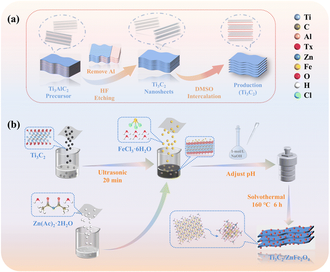 |
| | Fig. 1 Schematic of (a) Ti3C2 and (b) synthesis of the Ti3C2/ZnFe2O4 heterostructure. | |
3. Results and discussion
3.1. Characterisation of catalysts
3.1.1. Analysis of the crystal structure and composition.
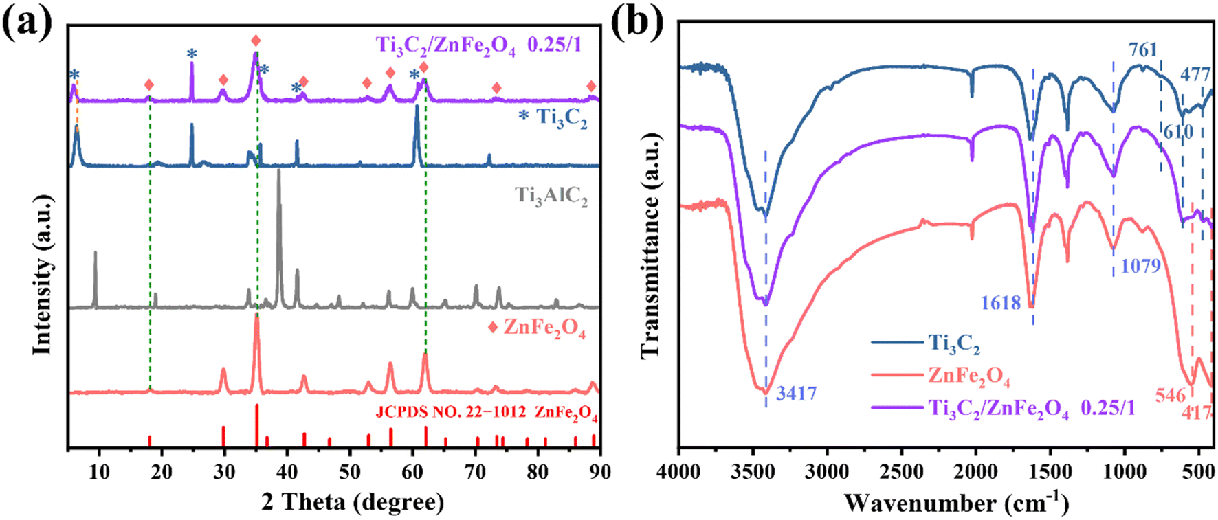
The crystal structures of the single substances Ti3C2 and ZnFe2O4 and the composite 0.25/1 Ti3C2/ZnFe2O4 were analysed using X-ray diffraction (XRD). As shown in Fig. 2(a), the characteristic diffraction peaks appearing in the XRD pattern of the single substance Ti3C2 are consistent with those reported in the literature,22 confirming the successful etching of Ti3AlC2 to Ti3C2.23 The characteristic peak of anatase (TiO2) (JCPDS: 21-1272)24 appeared at 24.96° due to certain oxidation during the Ti3C2 preparation. The characteristic peaks corresponding to every diffraction angle appearing in the single substance ZnFe2O4 are attributed to the standard cubic phase of spinel ZnFe2O4 (JCPDS: 22-1012). From the XRD pattern of the composite material 0.25/1 Ti3C2/ZnFe2O4, it can be observed that adding Ti3C2 does not affect the crystal structure of ZnFe2O4, while the characteristic peaks of Ti3C2 and ZnFe2O4 appear in the composite structure, confirming the heterojunction formation. Furthermore, the intensity of the diffraction peak at 24.96° did not decrease in the composite, indicating that some of the Ti3+ in the composite was converted to Ti4+ and formed TiO2 due to in situ growth. Notably, some variations in the peak shape (widening) and positions (6.58°, 18.1°, 35.2°, 62.1°) are slightly shifted in the direction of the decreasing diffraction angle; such phenomena are related to the grain size, lattice distortion and residual stresses (microscopic and macroscopic).25–27 This is because of the influence of different ion/composition changes on the crystalline phase. Ions with larger radii replace those with smaller radii in the structure, resulting in an increase in the lattice spacing, causing the peak shape and position to accordingly change. Furthermore, this confirms the existence of strong interactions between semiconductors. Meanwhile, the peak position of Ti3C2 decreases (6.58°) because of the peak shift caused by the occurrence of ethylene glycol alcoholisation and alkalisation reactions under solvothermal conditions, resulting in the enrichment of –OH and –O groups28 and promoting close binding between substances. The functional groups of the prepared samples and the functional group interaction states between the substances were investigated using Fourier transform infrared (FTIR) spectroscopy. Fig. 2(b) presents the FTIR spectra of Ti3C2, ZnFe2O4 and 0.25/1 Ti3C2/ZnFe2O4. The vibrational peak at 477 cm−1 in the Ti3C2 spectrum is attributed to the Ti–C telescopic vibration and the peaks at 610 and 761 cm−1 are attributed to the Ti–O telescopic vibration.29 In the FTIR spectrum of ZnFe2O4, the two absorption peaks between 400 and 600 cm−1 are related to the bonding of metal cations and oxygen anions at tetrahedral and octahedral sites; i.e. they are related to the inherent telescopic vibration of metallic tetrahedral Fe–O (500–600 cm−1) and octahedral Zn–O (400–480 cm−1),30 respectively. Furthermore, the vibration peaks at 1079, 1618 and 3413 cm−1 are attributed to O–H bonds or the stretching and bending vibrations of adsorbed H2O molecules.31 This indicates that the characteristic structure of the precursor in the synthesised sample remains unchanged.
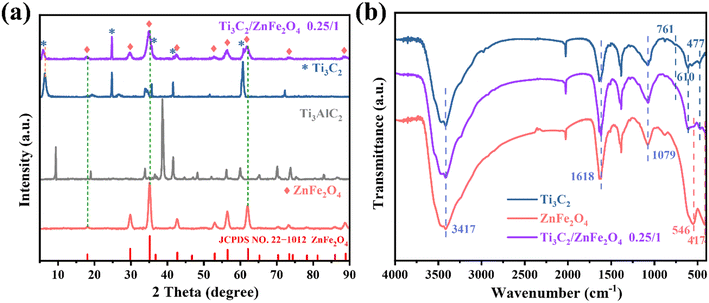 |
| | Fig. 2 (a) X-ray diffraction (XRD) patterns and (b) Fourier transform infrared spectra of the raw Ti3AlC2 and Ti3C2, pure ZnFe2O4 and the 0.25/1 Ti3C2/ZnFe2O4 composite. | |
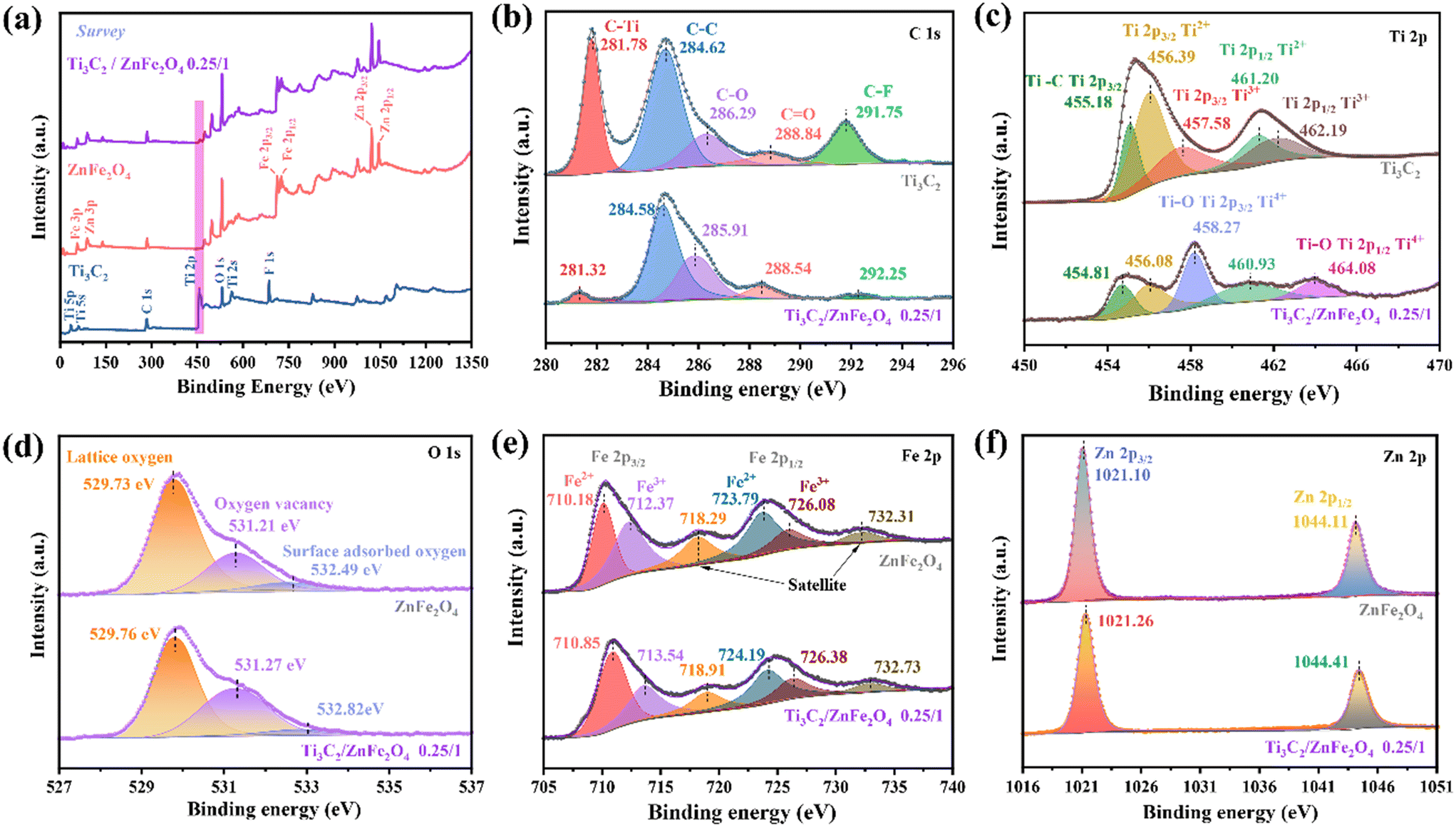
Furthermore, the changes in the surface elemental composition and chemical bonding state observed in Ti3C2, ZnFe2O4 and the 0.25/1 Ti3C2/ZnFe2O4 composite were analysed using X-ray photoelectron spectroscopy (XPS). The XPS spectrum presented in Fig. 3(a) indicates the presence of characteristic peaks for C 1s, Ti 2p, O 1s, Fe 2p and Zn 2p in the 0.25/1 Ti3C2/ZnFe2O4 composite, confirming the successful construction of a heterojunction, which is consistent with the conclusions of XRD analyses. The five anti-convolution peaks of the C 1s spectrum occur at 281.78 (C–Ti), 284.62 (C–C), 286.29 (C–O), 288.84 (C![[double bond, length as m-dash]](https://www.rsc.org/images/entities/char_e001.gif) O, alkyl carbon on the benzene ring) and 291.75 eV (C–F) [Fig. 3(b)].32 After binding with ZnFe2O4, the intensity of the C–Ti peak at 281.78 eV became considerably weak, indicating that the C–Ti bond is broken because of the shearing action of alkali during the synthesis process, promoting the exposure of Ti species and producing more active sites at the surface. Simultaneously, following alcoholisation and alkali treatment, the F content of the surface is considerably reduced, indicating the substitution of the end group. The XPS fine spectrum of Ti 2p [Fig. 3(c)] reveals characteristic peaks for Ti 2p3/2 (455.18, 456.39 and 457.58 eV) and Ti 2p1/2 (461.20 and 462.19 eV) corresponding to Ti–C, Ti2+, Ti3+, Ti2+ and Ti3+, respectively. In the high-resolution Ti 2p XPS spectrum of the composite, the peaks at 464.08 and 458.27 eV are attributed to Ti–O (Ti4+ 2p1/2)33 and Ti–O bonds at the end groups of Ti3C2, respectively; the latter occurred primarily due to the presence of Ti on the surface in the form of Ti4+ under alkaline conditions.19 This is in agreement with the C 1s analysis, favouring the formation of strong connections between substances to promote the formation of heterojunctions.34 Compared with that of the original Ti3C2, the 2p spectrum of low-valency Ti is weaker, indicating that low-valency Ti is consumed during the synthesis of the composite.35 Notably, the glycol solvent heat treatment under alkaline conditions, which is similar to those in saponification and alcohol halogenation, causes an increase in the density of –O terminations at the surface of the pristine HF-etched Ti3C2 and the conversion of the –F group to enrich the hydrophilic –OH group,28 thereby obtaining abundant metal–oxygen bonds (Ti–O) that help in promoting the bonding of Ti3C2 and ZnFe2O4 [Fig. 3(d)]. The spectral peak at 529.73 eV in O 1s is characteristic of lattice oxygen in metal oxides. The characteristic peak at 531.21 eV occurs due to the lack of lattice oxygen during the solvothermal process, and the increase in the relative intensity of complex oxygen vacancies at the corresponding peak positions indicates an increase in the content of oxygen vacancies, indicating the accumulation of numerous photocatalytically active centres.36 Furthermore, electron paramagnetic resonance characterisation demonstrates the formation of oxygen vacancies in the synthesised samples (Fig. S2†). In addition, the peak at 532.49 eV denotes oxygen adsorption and the corresponding binding energy of the composite is observed to slightly increase because of the reduction of the adsorbed oxygen content, enhancing the lattice vibration and promoting the generation of e− or h+, thereby improving the photocatalytic performance of the material.37 As shown in Fig. 3(e), the high-resolution spectrum of Fe 2p can be divided into three types of peaks, which are characterised by two spin–orbit splitting peaks (Fe 2p3/2: 710.18 and 712.37 eV, corresponding to the octahedral and tetrahedral positions of spinel ferrite, respectively; Fe 2p1/2: 723.79 and 726.08 eV) and a satellite peak (718.29 and 732.31 eV). The characteristic peaks at 710.18 and 723.79 eV indicate the presence of Fe2+ (charge carrier) due to e− hopping at the octahedral position. The characteristic peaks at the binding energies of 712.37 and 726.08 eV indicate the presence of Fe3+ in the synthetic material, whereas the satellite peaks at 718.29 and 732.31 eV indicate the presence of Fe3+ with the corresponding binding energy in the composites. For the characteristic spectrum of Zn 2p [Fig. 3(f)], 1021.10 (Zn 2p3/2) and 1044.11 eV (Zn 2p1/2) correspond to Zn2+ occupying the tetrahedral and octahedral positions, respectively.38 For nano-scale ZnFe2O4, the cations that originally occupied the above two positions in the spinel structure are reassigned and these movements exhibit a considerable effect on the electronic, magnetic and catalytic properties of the material.31 Notably, the spectral peaks of the individual elements of the composite material shift in the direction of high or low binding energy compared to those of the single material. This indicates the formation of heterojunctions in which the strong interactions among the elements cause changes in the e− density in the interfacial region,39 providing favourable evidence for the interactions between charge transfer and degradation target products.
O, alkyl carbon on the benzene ring) and 291.75 eV (C–F) [Fig. 3(b)].32 After binding with ZnFe2O4, the intensity of the C–Ti peak at 281.78 eV became considerably weak, indicating that the C–Ti bond is broken because of the shearing action of alkali during the synthesis process, promoting the exposure of Ti species and producing more active sites at the surface. Simultaneously, following alcoholisation and alkali treatment, the F content of the surface is considerably reduced, indicating the substitution of the end group. The XPS fine spectrum of Ti 2p [Fig. 3(c)] reveals characteristic peaks for Ti 2p3/2 (455.18, 456.39 and 457.58 eV) and Ti 2p1/2 (461.20 and 462.19 eV) corresponding to Ti–C, Ti2+, Ti3+, Ti2+ and Ti3+, respectively. In the high-resolution Ti 2p XPS spectrum of the composite, the peaks at 464.08 and 458.27 eV are attributed to Ti–O (Ti4+ 2p1/2)33 and Ti–O bonds at the end groups of Ti3C2, respectively; the latter occurred primarily due to the presence of Ti on the surface in the form of Ti4+ under alkaline conditions.19 This is in agreement with the C 1s analysis, favouring the formation of strong connections between substances to promote the formation of heterojunctions.34 Compared with that of the original Ti3C2, the 2p spectrum of low-valency Ti is weaker, indicating that low-valency Ti is consumed during the synthesis of the composite.35 Notably, the glycol solvent heat treatment under alkaline conditions, which is similar to those in saponification and alcohol halogenation, causes an increase in the density of –O terminations at the surface of the pristine HF-etched Ti3C2 and the conversion of the –F group to enrich the hydrophilic –OH group,28 thereby obtaining abundant metal–oxygen bonds (Ti–O) that help in promoting the bonding of Ti3C2 and ZnFe2O4 [Fig. 3(d)]. The spectral peak at 529.73 eV in O 1s is characteristic of lattice oxygen in metal oxides. The characteristic peak at 531.21 eV occurs due to the lack of lattice oxygen during the solvothermal process, and the increase in the relative intensity of complex oxygen vacancies at the corresponding peak positions indicates an increase in the content of oxygen vacancies, indicating the accumulation of numerous photocatalytically active centres.36 Furthermore, electron paramagnetic resonance characterisation demonstrates the formation of oxygen vacancies in the synthesised samples (Fig. S2†). In addition, the peak at 532.49 eV denotes oxygen adsorption and the corresponding binding energy of the composite is observed to slightly increase because of the reduction of the adsorbed oxygen content, enhancing the lattice vibration and promoting the generation of e− or h+, thereby improving the photocatalytic performance of the material.37 As shown in Fig. 3(e), the high-resolution spectrum of Fe 2p can be divided into three types of peaks, which are characterised by two spin–orbit splitting peaks (Fe 2p3/2: 710.18 and 712.37 eV, corresponding to the octahedral and tetrahedral positions of spinel ferrite, respectively; Fe 2p1/2: 723.79 and 726.08 eV) and a satellite peak (718.29 and 732.31 eV). The characteristic peaks at 710.18 and 723.79 eV indicate the presence of Fe2+ (charge carrier) due to e− hopping at the octahedral position. The characteristic peaks at the binding energies of 712.37 and 726.08 eV indicate the presence of Fe3+ in the synthetic material, whereas the satellite peaks at 718.29 and 732.31 eV indicate the presence of Fe3+ with the corresponding binding energy in the composites. For the characteristic spectrum of Zn 2p [Fig. 3(f)], 1021.10 (Zn 2p3/2) and 1044.11 eV (Zn 2p1/2) correspond to Zn2+ occupying the tetrahedral and octahedral positions, respectively.38 For nano-scale ZnFe2O4, the cations that originally occupied the above two positions in the spinel structure are reassigned and these movements exhibit a considerable effect on the electronic, magnetic and catalytic properties of the material.31 Notably, the spectral peaks of the individual elements of the composite material shift in the direction of high or low binding energy compared to those of the single material. This indicates the formation of heterojunctions in which the strong interactions among the elements cause changes in the e− density in the interfacial region,39 providing favourable evidence for the interactions between charge transfer and degradation target products.
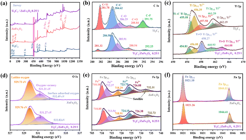 |
| | Fig. 3 (a) XPS survey spectra of Ti3C2, ZnFe2O4 and 0.25/1 Ti3C2/ZnFe2O4, and (b) C 1s, (c) Ti 2p, (d) O 1s, (e) Fe 2p, and (f) Zn 2p spectra of the synthesised materials. | |
3.1.2. Morphological characterisation.
The morphologies of pure substances Ti3C2 and ZnFe2O4 and the 0.25/1 Ti3C2/ZnFe2O4 nano-composite were investigated using field-emission scanning electron microscopy. Fig. 4(a) and (b) reveal the successful preparation of a typical MXene multilayer accordion-like material Ti3C2, and it can be observed that the flakes are thin layers. 0.25/1 Ti3C2/ZnFe2O4 is a heterojunction synthesised through loading several ZnFe2O4 nanoparticles onto the surface and partial interlayer of 2D layered Ti3C2 [Fig. 4(c) and (d)]. The surface particles of ZnFe2O4 and the composite photocatalyst present irregular shapes, surface roughness and agglomeration phenomena, which may be caused by the electrostatic interaction, polarity and high surface energy between zinc ferrite particles.40 Furthermore, transmission electron microscopy (TEM) and high-resolution TEM (HRTEM) images reveal the microstructure of the 0.25/1 Ti3C2/ZnFe2O4 nano-composite. The formation of a tight heterojunction structure between the ZnFe2O4 nanoparticles (red circles) and Ti3C2 can be clearly observed [Fig. 4(e)]. The yellow circle in Fig. 4(e) corresponds to the partial enlargement shown in Fig. 4(f), where the lattice stripes characterised by crystal plane spacings (d) of 0.209 and 0.252 nm correspond to the (105) and (311) crystal planes of Ti3C2 and ZnFe2O4, respectively. Furthermore, the lattice of the catalytic material is twisted, which is caused by the destruction of the equilibrium state among the atoms due to alkaline conditions and different occupations between ions. The elemental diagram (Fig. S3†) and energy-dispersive X-ray spectroscopy (EDX) analysis of the Ti3C2/ZnFe2O4 binary system [Fig. 4(g)–(l)] indicate that Ti, C, Zn, Fe and O in the 0.25/1 Ti3C2/ZnFe2O4 composite are uniformly distributed throughout the region. The structural characteristics of the materials (specific surface area and pore structure) were analysed using N2 adsorption–desorption isotherms. Hysteresis loops of different sizes are observed for isotherms under different relative pressures [Fig. S4(a)†], indicating the presence of mesoporous structures in all the samples. The BET values of Ti3C2, ZnFe2O4 and 0.25/1 Ti3C2/ZnFe2O4 were 40.534, 238.159 and 130.858 m2 g−1, respectively. BJH analysis indicated that the average pore sizes of the abovementioned samples were 3.704, 7.726 and 5.589 nm, respectively [Fig. S4(b)†]; detailed data are presented in Table S1.† The coupled specific surface area, total pore volume and pore size of Ti3C2 and ZnFe2O4 were observed to increase relative to those of Ti3C2, providing more active sites and enhancing the adsorption capacity of TCH. Unlike that for ZnFe2O4, its monolayer adsorption cannot completely explain the TCH adsorption.41
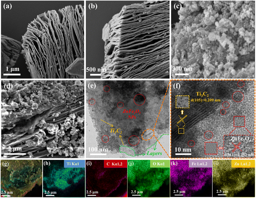 |
| | Fig. 4 FESEM patterns of (a and b) Ti3C2, (c) ZnFe2O4, and (d) 0.25/1 Ti3C2/ZnFe2O4, (e) TEM image of 0.25/1 Ti3C2/ZnFe2O4, (f) HRTEM images of 0.25/1 Ti3C2/ZnFe2O4 [partial enlarged image corresponding to the yellow circle area in Fig. 4(e)] and (g–l) elemental mapping images of 0.25/1 Ti3C2/ZnFe2O4. | |
3.1.3. Optical and electrochemical analysis.
To study the optical and electrochemical properties of the prepared photocatalytic materials, ultraviolet–visible diffuse reflectance spectroscopy (UV–vis DRS), photoluminescence (PL) spectroscopy, time-resolved photoluminescence (TR-PL) spectroscopy, photocurrent (PC) analysis and electrochemical impedance spectroscopy (EIS) were performed. UV–vis DRS spectra [Fig. 5(a)] reveal the light absorption characteristics of the photocatalysts, indicating no obvious absorption edge in the absorption curve for Ti3C2; this is related to the particular energy band structure and metallic properties of Ti3C2.42 Compared to pure ZnFe2O4, the visible light absorption of the 0.25/1 Ti3C2/ZnFe2O4 composite is enhanced and the absorption edge is red-shifted. This is caused by the strong interactions during the group transition, leapfrogging of orbital e− within tetrahedra and octahedra or the bandgap mixing effect that introduces defects.43 The bandgap energy was calculated using the Kubelka–Munk equation [Fig. 5(b)]; the Ti3C2, ZnFe2O4 and 0.25/1 Ti3C2/ZnFe2O4 bandgap values were 1.19, 2.04 and 1.90 eV, respectively. The bandgap energy and width of ZnFe2O4 were reduced owing to local defects or exchanges between local and band e− (charge neutralisation creates some oxygen vacancies) and interaction after successful loading of the group,44 resulting in a composite material with improved visible light absorption. The efficient separation of photogenerated carriers is one of the key factors required for the improvement of photocatalytic activity, and PL spectroscopy can be used to analyse the separation efficiency capacity of charge trapping and e−–h+ pairs in semiconductors. Fig. 5(c) depicts the PL spectra of the sample at an excitation wavelength of 386 nm, where Ti3C2 acts as an e− acceptor, trapping e− and quenching several steady-state PL spectra of ZnFe2O4 (ref. 45) due to the formation of heterojunctions between substances that promote interfacial charge transport. In addition, the optical behaviour of the e−–h+ pairs of the photocatalytic materials was investigated using TR-PL spectroscopy [Fig. 5(d); trapped e− lifetimes were fitted and analysed, and specific parameters and calculations are presented in Table S2†]. The average decay lifetimes of the prepared materials were calculated, indicating that the heterojunction 0.25/1 Ti3C2/ZnFe2O4 (1.724 ns) exhibits a longer carrier lifetime than Ti3C2 (1.353 ns) and ZnFe2O4 (1.450 ns), thereby facilitating the photocatalytic reaction. The transient photocurrent behaviour of the photocatalytic materials Ti3C2, ZnFe2O4 and 0.25/1 Ti3C2/ZnFe2O4 was investigated to evaluate the e−–h+ separation rate. The photocurrent of the 0.25/1 Ti3C2/ZnFe2O4 composite considerably increases compared to that of a single substance, implying high carrier separation efficiency and explaining the longer lifetime of the composite [Fig. 5(e)]. To verify the charge transfer capability of 0.25/1 Ti3C2/ZnFe2O4, the EIS Nyquist plots of each substance were determined and analysed [Fig. 5(f)]. The radius of the Nyquist semicircle located in the high frequency region is related to the charge transfer process at the photoelectrode interface such that the smaller the radius, the higher the charge transfer efficiency. This indicates that alcoholisation and alkalinisation under solvent heating enrich Ti3C2 with hydrophilic groups (–OH and –O), forming a tight heterojunction with ZnFe2O4, reducing resistance to e− transport, enhancing responses to visible light, promoting efficient carrier separation and interfacial charge transfer rate, prolonging the carrier lifetime and improving the photocatalytic performance.
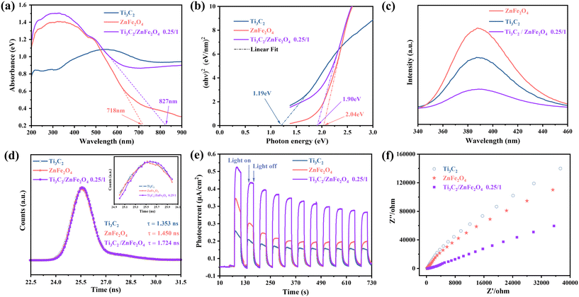 |
| | Fig. 5 (a) UV–vis DRS spectra, (b) Tauc plots, (c) PL spectra, (d) TR-PL spectra, (e) transient photocurrent responses, and (f) EIS Nyquist plots of Ti3C2, ZnFe2O4 and 0.25/1 Ti3C2/ZnFe2O4. | |
3.2. Photocatalytic performance test
Photocatalytic degradation tests performed on TCH under visible light irradiation allowed the photocatalytic activity of the sample to be investigated. Fig. 6(a) and (b) show the removal efficiency of TCH with and without a photocatalyst; TCH undergoes little photolysis in the absence of a catalyst owing to its high chemical stability. Under visible light irradiation, 0.25/1 Ti3C2/ZnFe2O4 exhibited the highest total removal of TCH (87.10%) owing to the synergistic effect, adsorption and photocatalysis. Its removal rate was 1.4 and 11.3 times higher than those of ZnFe2O4 (62.66%) and Ti3C2 (7.73%). The oxygen-containing groups (–OH and –O) and oxygen-active sites of Ti3C2 increase following the alcoholisation and alkalinisation reactions performed under solvent heating, during which the heterojunction formed between Ti3C2 and ZnFe2O4 enhances the absorption of visible light and carrier separation efficiency, improving the photocatalytic degradation performance. According to the kinetics [Fig. 6(c)], light conditions with −ln(Ct/C0) are consistent with the first-order kinetics. Fig. 6(d) depicts the rate constant k, with 0.25/1 Ti3C2/ZnFe2O4 exhibiting the highest reaction kinetic constant (0.01197 min−1) (i.e. 2.0 and 35.2 times higher than those of Ti3C2 and ZnFe2O4, respectively). The effects of different catalysts on the apparent rate of decline, kinetic constants and correlation coefficients for TCH degradation are summarised in Table S3.† Additionally, the photodegradation efficiency of 0.25/1 Ti3C2/ZnFe2O4 and other types of photocatalysts on TCH was compared (Table S4†), revealing that the 0.25/1 Ti3C2/ZnFe2O4 composite catalyst exhibits a higher efficiency for the removal of tetracycline from the aqueous environment and realistic significance for practical applications. To study the stability of the catalyst, a cycling experiment [Fig. S5(a)†] was performed, revealing that the catalytic efficiency was reduced because the e− accumulated by Ti3C2 is consumed by the reduction reaction of Fe while participating in the photocatalytic degradation. The TCH or intermediate on the catalyst surface is not completely resolved such that some active sites are occupied, influencing the photocatalytic efficiency during the cycle. Moreover, the structures of the recovered samples were analysed [Fig. S5(b)†]. XRD characterisation indicated that the corresponding peak intensity of the recovered sample lightly changed compared to the fresh sample. This is related to the partial shedding of the surface-loaded ZnFe2O4. However, no considerable difference was observed, indicating that the sample retained high recyclability and structural integrity after the cycling experiment. Adsorption was investigated to exclude the effect of dark adsorption on the subsequent photodegradation (Fig. S6†), indicating that the removal of TCH via dark adsorption was not considerable; the subsequent target pollutant (i.e. TCH) still needed to be degraded under light.
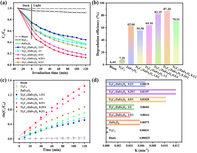 |
| | Fig. 6 (a) Degradation curves of the photocatalytic degradation of tetracycline by composite materials, (b) histogram of the photocatalytic degradation efficiency of tetracycline by different materials, (c) fitting curves of the pseudo-first-order kinetics and (d) degradation rate constant K. | |
3.3. Analysis of intermediate products and degradation pathways
To explore the intermediates of composite photocatalysts in the photocatalytic degradation of TCH, the intermediate product (Fig. S7†) was identified using HPLC–MS. The intensity of the TCH signal at m/z = 445.16 was observed to gradually decrease with the progressing reaction, generating different mass spectral peaks, demonstrating that TCH was decomposed into different intermediates (Table S5† presents molecular formulas and details). Based on the detected intermediates and their analysis (Fig. S7†), three possible pathways by which TCH could be degraded into smaller molecules by active radical (·O2−, h+ and ·OH) attack when exposed to visible light may be proposed (Fig. 7 and Table S5†). In pathway I, because of the attack of h+, the intermediate P1 (m/z = 417.16) was formed by the demethylation of TCH. This was further converted to the intermediate P4 (m/z = 433.28) via hydroxylation. The hydroxyl, double bond and amine in TCH are relatively susceptible to the attack by active free radicals in the photocatalytic process;46 here, P4 (m/z = 433.28) can be degraded into smaller molecules by two approaches – deamidation and carboxylation – to produce the by-product P8 (m/z = 282.20). Furthermore, it can be gradually cleaved by a ring-opening reaction and ketonised to form a low-molecular-weight ketone compound P9 (m/z = 268.19), which can then be carboxylated to form the carboxylic acid compound P10 (m/z = 119.08).47 In pathway II, the double bond of the TCH molecule can be hydroxylated (addition) to form intermediate P2 (m/z = 461.15). Furthermore, removal of the –N(CH3)2 functional group and radical oxidation of the double bond provide intermediate P5 (m/z = 432.24),48 and the subsequent removal of enol, amide and H2O produces the intermediate P6 (m/z = 318.30).49 In addition, P5 (m/z = 432.24) can be generated by the cleavage of the double bond (ring-opening reaction) to form intermediate P7 (m/z = 439.15). P5 and P7 can then be sequentially cleaved via the ring-opening reactions to form intermediate P11 (m/z = 274.27). In pathway III, TCH (m/z = 445.16) underwent demethylation and deformylation to generate intermediate P3 (m/z = 388.25),50 which was further decomposed via the ring-opening, H2O removal and deamination reactions to produce intermediate P12 (m/z = 227.17).51 Eventually, these organic compounds continue to be mineralised to CO2, H2O and other small molecules under attack by free radicals, as demonstrated by TOC analysis (59.75% TOC degradation after 2 h of light; Fig. S8†). By introducing Ti3C2, an association of ZnFe2O4 grows in situ, i.e. a heterojunction is constructed between the two. This heterojunction produces active substances under visible-light conditions, destroying the structure of the target pollutant and generating several intermediates that ultimately degrade TCH into small molecules (CO2 and H2O) that are not toxic to the environment.
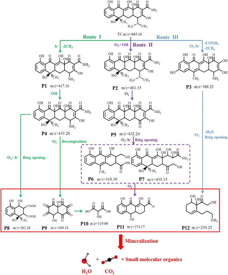 |
| | Fig. 7 Possible degradation pathway of TCH under visible-light irradiation. | |
3.4. Exploration of active substances and photocatalytic mechanisms
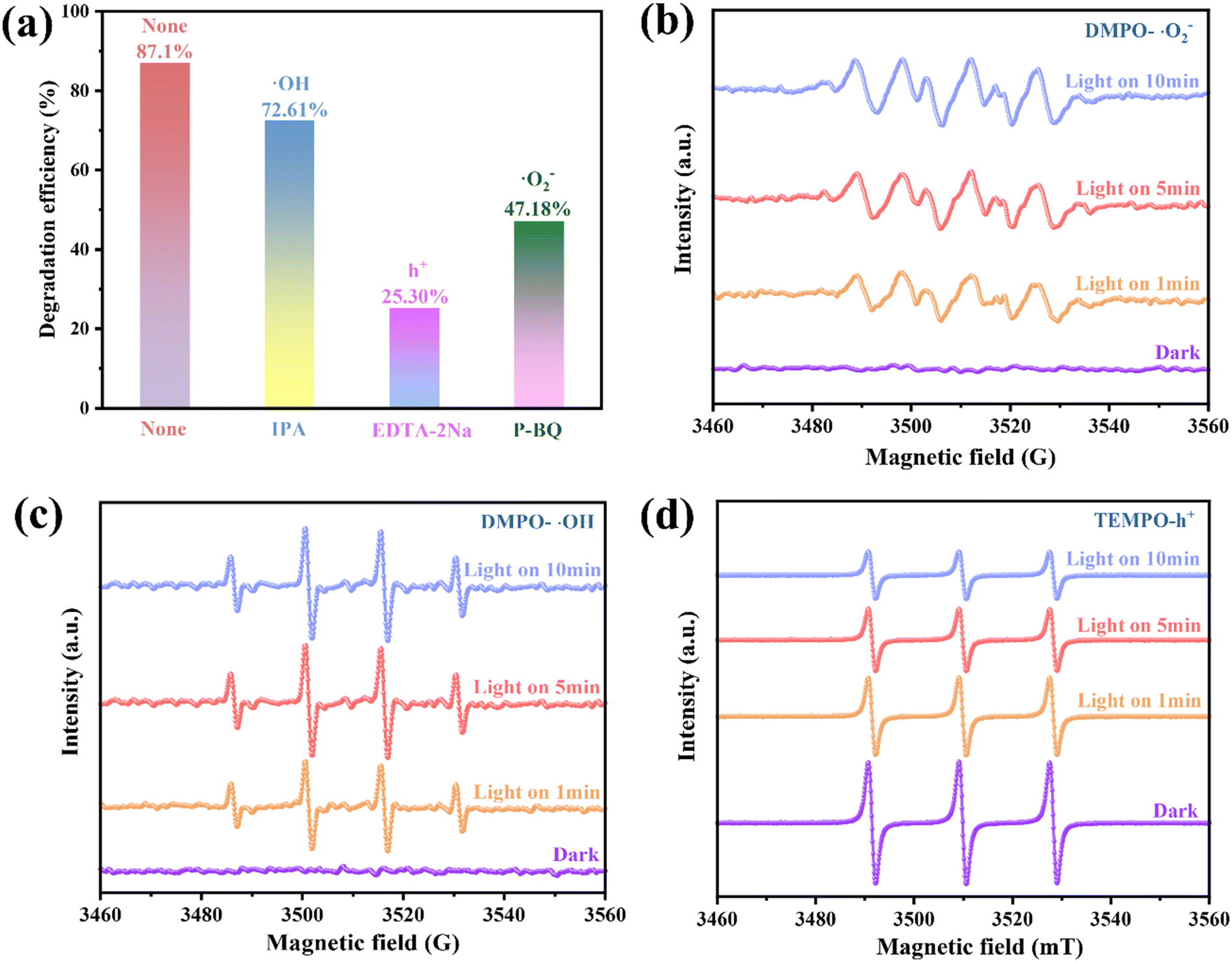
Catalyst photodegradation reactions generally involve the participation of ·OH, h+ and ·O2−. To better identify the main active substances and the charge transfer mechanisms involved during TCH degradation, IPA, EDTA-2Na and P-BQ were introduced into the reaction system as trapping agents for ·OH, h+ and ·O2−, respectively.52 The TCH removal rate decreased to 25.30% following the addition of EDTA-2Na, which was considerably lower than the TCH removal rate of 0.25/1 Ti3C2/ZnFe2O4 (87.10%) [Fig. 8(a)]. The P-BQ addition reduced the removal rate to 47.18%. In the presence of IPA, the removal rate of TCH was 72.61%, i.e. little effect on the degradation was observed. The above results indicate that ·O2− and h+ are the main active components involved in the photocatalytic degradation. On this basis, the active free radicals in the photoreaction process were verified using electron spin resonance (ESR) spectroscopy. As shown in Fig. 8(b) and (c), under visible light irradiation, the intensity ratio of the four peaks attributed to the characteristic signals of DMPO–·OH and DMPO–·O2− is 1![[thin space (1/6-em)]](https://www.rsc.org/images/entities/char_2009.gif) :2:2:1 and the four strong group peaks of 1:1:1:1 (ref. 53) are considerably enhanced compared to those under dark conditions, verifying that the active substances ·OH and ·O2− generated under illumination accelerate the separation and transfer of space charges. The increase in the illumination time enhances the relative strength of the active group, indicating a corresponding increase in the yield. Although 2,2,6,6-tetramethylpiperidine oxide (TEMPO) reacts with h+ to form spin adducts, the ESR signal gradually weakens with increasing illumination time, verifying the presence of h+ [Fig. 8(d)].54 This indicates that the photogenerated carriers in the 0.25/1 Ti3C2/ZnFe2O4 composite exhibit superior e−–h+ pair separation properties under light irradiation.
:2:2:1 and the four strong group peaks of 1:1:1:1 (ref. 53) are considerably enhanced compared to those under dark conditions, verifying that the active substances ·OH and ·O2− generated under illumination accelerate the separation and transfer of space charges. The increase in the illumination time enhances the relative strength of the active group, indicating a corresponding increase in the yield. Although 2,2,6,6-tetramethylpiperidine oxide (TEMPO) reacts with h+ to form spin adducts, the ESR signal gradually weakens with increasing illumination time, verifying the presence of h+ [Fig. 8(d)].54 This indicates that the photogenerated carriers in the 0.25/1 Ti3C2/ZnFe2O4 composite exhibit superior e−–h+ pair separation properties under light irradiation.
 |
| | Fig. 8 (a) Effect of radical scavengers on the removal of TCH and ESR spectra of (b) DMPO–·O2−, (c) DMPO–·OH and (d) TEMPO–h+ for 0.25/1 Ti3C2/ZnFe2O4 under visible light irradiation. | |
In addition, the photocatalytic activity of the system depends on the positions of the conduction band (CB) and valence band (VB). The VB-XPS spectrum (Fig. S9†) was used to clarify the CB and VB potential of the photocatalytic material and the e− migration paths of Ti3C2 and ZnFe2O4 during the interaction at the heterojunction interface. According to the formula EVB = ECB + Eg, the EVB values of Ti3C2, ZnFe2O4 and 0.25/1 Ti3C2/ZnFe2O4 are approximately 0.65, 1.03 and 1.09 eV and the corresponding ECB values are −0.54, −1.01 and −0.81 eV, respectively. Because Ti3C2 acts as an ‘e− trap’, the e− density at the Fermi energy level is high, further changing the forbidden band width and enhancing its response to visible light. Based on the above analysis, a possible mechanism for photocatalytic degradation is proposed (Fig. 9). During the process of the photoinduced generation of photogenerated e− and h+, the terminal group of Ti3C2 promotes the accumulation of photogenerated e− owing to the loading of –OH and –O hydrophilic groups, forming a space charge layer (built-in electric field) near the interface of Ti3C2/ZnFe2O4. The metal–oxygen clusters in the n-type semiconductor ZnFe2O4 play the role of exciting photogenerated e−, and as its Fermi level (Ef ≈ ECB) is higher than that of Ti3C2 (Ef = −0.60 V),55 e− is driven through the contact interface between the two to transfer to the Ti3C2 CB until a uniform Fermi level is formed. Meanwhile, the h+ is stranded on the VB, forming a Schottky barrier at the interface between the two, in which excited e− crosses the interface and migrates in the form of a drift current beam and participates in the reaction such that no accumulation or recombination occurs.56 Simultaneously, because the reduction potential of Fe2+/Fe3+ (Fe2+/Fe3+ = −0.77 V)57 is lower than the ECB of ZnFe2O4, Fe captures the photogenerated e− of ZnFe2O4 and inhibits the recombination of e−–h+ pairs,55 effectively separating the carriers and improving the photocatalytic efficiency. For Ti3C2, the CB (ECB = −0.54 eV) is more negative than the potential of O2/·O2− (−0.33 eV vs. NHE), implying that its enrichment and the photoactivated e− trapped due to the presence of oxygen vacancies will be consumed to activate the dissolved O2 adsorbed onto the surface, reducing O2 to strongly oxidising superoxide radicals (·O2−).58 Subsequently, the reaction of ·O2− and H+ in water can produce secondary hydroxyl radicals (·OH),59 reacting with e− to produce H2O2, while Fe(II) can be converted into Fe(III) in the presence of H2O2 while producing ·OH. Because ZnFe2O4 exhibits EVB = 1.03 eV, which is more negative than the ·OH/OH− potential (+1.99 eV vs. NHE), the local water molecule cannot be oxidised to OH− by h+ at the VB but its h+ at the VB can directly oxidise the TCH molecule in water.53 This is in agreement with the results of ESR and active substance capture experiments. The specific reaction equation is presented as eqn (S1).†
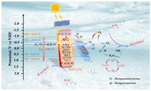 |
| | Fig. 9 Schematic of the photocatalytic mechanism of tetracycline hydrochloride (TCH) degradation by the 0.25/1 Ti3C2/ZnFe2O4 composite photocatalyst. | |
3.5. Ecological toxicity detection
To explore whether the intermediates formed during the 0.25/1 Ti3C2/ZnFe2O4 photocatalytic degradation of TCH are harmful to the aquatic environment, the toxicity of a specific case of 50% lethal concentrations (fish: 96 h, Daphnia: 48 h and green algae: 96 h) was modelled using the ECOSAR simulation. Lower acute toxicity levels (LC50) and chronic toxicity (ChV) values correspond to higher toxicity. The effects of TCH and its degradation products on fish, Daphnia and green algae, with the exception of individual substances [i.e. P3 and P5 in Fig. 10(e)], are essentially harmless to their development and growth (Fig. 10). In the aquatic environment, toxicity reduction or even non-toxicity is essential. Based on the above analysis, the intermediate formed is slightly toxic. Under visible light, TCH and its intermediates can be completely converted into small molecules, such as CO2 and H2O, as the mineralisation process proceeds, to attain completely non-toxic conditions.
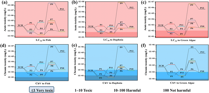 |
| | Fig. 10 Ecotoxicity of TCH and its by-products: (a)–(c) acute toxicity and (d)–(f) chronic toxicity. | |
4. Universality of the photocatalyst
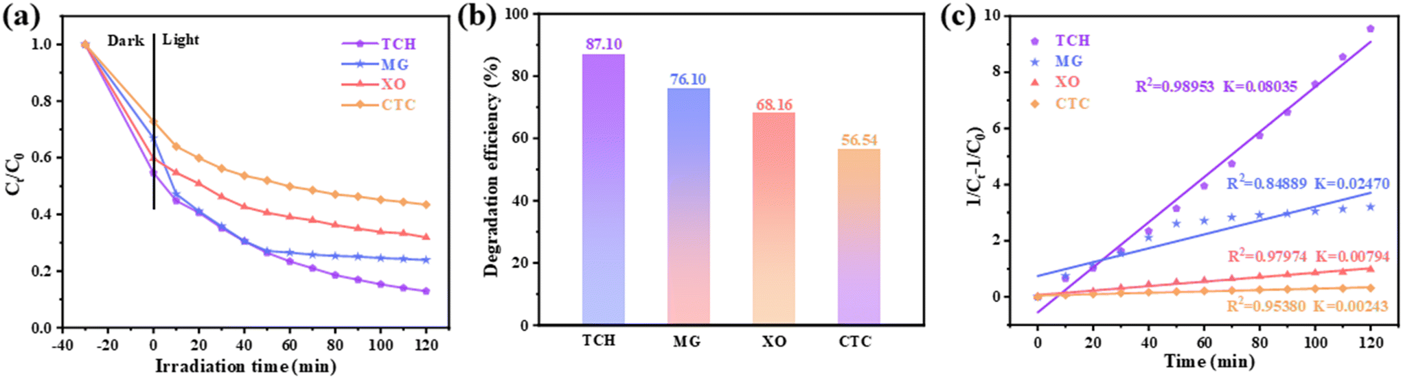
Based on the investigation of the degradation efficiency of TCH (Fig. 6) to explore the universality of the composite photocatalyst (0.25/1 Ti3C2/ZnFe2O4), malachite green (MG), xylenol orange (XO) and chlortetracycline (CTC) were used as target pollutants. Their UV–vis spectra were monitored at absorption wavelengths (λ) of 618, 460 and 275 nm, respectively, to evaluate the photocatalytic degradation efficiency [Fig. 11(a) and (b)]. Furthermore, their reaction kinetics [Fig. 11(c)] were analysed. Ti3C2 and ZnFe2O4 control experiments for the removal of the above pollutants are shown in Fig. S10.† The removal efficiencies of Ti3C2 for TCH, MG, XO and CTC were 7.29%, 7.73%, 3.36% and 2.41%, respectively, and those of ZnFe2O4 for TCH, MG, XO and CTC were 62.66%, 62.12%, 36.41% and 16.00%, respectively. However, the composite photocatalyst exhibited higher removal efficiencies for TCH (87.10%), MG (76.10%), XO (68.16%) and CTC (56.54%) [Fig. 11(a–c)]. In addition, by investigating the reaction kinetics of the photocatalytic degradation of the target pollutants by the composite photocatalyst [Fig. 11(c) and S11†], it was observed that TCH, MG, XO and CTC more closely followed the pseudo-second-order kinetics; the maximum value of the rate constants was 0.08035 (TCH), followed by 0.02470 (MG), 0.00794 (XO) and 0.00243 (CTC). The above analysis determined that the composite photocatalyst 0.25/1 Ti3C2/ZnFe2O4 exhibits high adaptability to pollutants in water, which is attributed to the active free radicals generated by the photocatalyst under light conditions, accompanied by a series of reactions, thereby further degrading the target pollutants.
 |
| | Fig. 11 (a) Degradation curves of water pollutants malachite green, xylenol orange and chlortetracycline hydrochloride under visible light and (b) the corresponding degradation efficiency histogram and (c) pseudo-second-order kinetics analysis using 0.25/1 Ti3C2/ZnFe2O4 as the photocatalyst. | |
5. Conclusions
A photocatalytic material with a stable interface and high catalytic efficiency was prepared via simultaneously performing alcoholisation and alkalisation using a simple solvothermal method. The heterojunction constructed is coupled from an n-type semiconductor (ZnFe2O4) and a metal semiconductor rich in metal–oxygen groups owing to alkalisation and ethylene glycol alcoholisation (Ti3C2), exhibiting a close surface–interface contact, a strong visible-light response, a high photogenerated e−–h+ pair separation efficiency, a satisfactory electron transfer rate and high photocatalytic activity. Under visible-light (λ > 420 nm) irradiation, the removal rate of TCH was 87.10%, and its mineralisation rate was 59.75%. ·OH, h+ and ·O2− were identified as the active components in the degradation of TCH, and based on this a possible pathway for TCH degradation was proposed. Toxicity risk assessment revealed that in the presence of 0.25/1 Ti3C2/ZnFe2O4, the photodegradation of TCH reduces its toxicity and potential risk to the aquatic environment. Universality exploration demonstrated that the photocatalyst exhibits a good response capability to other pollutants in water bodies. Consequently, this study fully confirms the photocatalytic mechanism of Ti3C2/ZnFe2O4 heterojunctions through experimental and theoretical analyses, yielding several new ZnFe2O4-based heterojunction photocatalysts, describing their construction and providing a new approach to the photocatalytic degradation of water pollutants.
Author contributions
Hongqing He: conceptualisation, data curation, formal analysis, investigation, methodology, writing – original draft, writing – review & editing. Yu Fang: validation. Xinhao Sun: formal analysis. Xianbin Li: formal analysis. Shunzhi Li: formal analysis. Yang Cao: conceptualisation, funding acquisition, resources, writing – review & editing.
Conflicts of interest
The authors declare that they have no known competing financial interests or personal relationships that could have appeared to influence the work reported in this paper.
Acknowledgements
This work was supported by the National Natural Science Foundation of China [No. 52161029], the Guizhou Science and Technology Cooperation Foundation-ZK[2021] General 243, and the Research Project of Introducing Talents of Guizhou University: No. 60, Renjihe Zi (2020).
References
- J. Dhayanantha Prabu, A. Pandiyarajan, C. Ruo-Syuan, Y. Wen-Yueh, W. Ming-Show and F. Yen-Pei, J. Environ. Chem. Eng., 2023, 11, 109852 CrossRef.
- F. Saadati, N. Keramati and M. M. Ghazi, Crit. Rev. Environ. Sci. Technol., 2016, 46, 757–782 CrossRef CAS.
- H. Xu, Y. Zhang, Y. Wang, L. Zhang, Z. Zhang, L. Zhong, Z. He, Y. Zheng and Y. Shen, Carbohydr. Polym., 2023, 3112, 120829 CrossRef.
- D. Chen, Y. Cheng, N. Zhou, P. Chen, Y. Wang, K. Li, S. Huo, P. Cheng, P. Peng, R. Zhang, L. Wang, H. Liu, Y. Liu and R. Ruan, J. Cleaner Prod., 2020, 268, 121725 CrossRef CAS.
- L. Ji, W. Chen, L. Duan and D. Zhu, Environ. Sci. Technol., 2009, 43, 2322–2327 CrossRef CAS PubMed.
- F. Dong, Z. Wang, Y. Li, W.-K. Ho and S. C. Lee, Environ. Sci. Technol., 2014, 48, 10345–10353 CrossRef CAS PubMed.
- A. H. Mady, M. L. Baynosa, D. Tuma and J.-J. Shim, Appl. Catal., B, 2016, 203, 416–427 CrossRef.
- A. Angkaew, C. Chokejaroenrat, C. Sakulthaew, J. Mao, T. Watcharatharapong, A. Watcharenwong, S. Imman, N. Suriyachai and T. Kreetachat, J. Environ. Chem. Eng., 2021, 9, 105621 CrossRef CAS.
- J. R. Sandemann, T. B. E. Grønbech, K. A. H. Støckler, F. Ye, B. C. Chakoumakos and B. B. Iversen, Adv. Mater., 2022, 35, 2207152 CrossRef.
- H. Qingzheng, W. Mingyong, L. Taiguang, H. Yaqi, X. Kai and H. Yongmei, J. Chem. Eng. Data, 2023, 464, 142566 CrossRef.
- T. Su, R. Peng, Z. D. Hood, M. Naguib, I. N. Ivanov, J. K. Keum, Z. Qin, Z. Guo and Z. Wu, ChemSusChem, 2018, 11, 688–699 CrossRef CAS PubMed.
- B. Anasori, M. R. Lukatskaya and Y. Gogotsi, Nat. Rev. Mater., 2017, 2, 1–17 Search PubMed.
- H. Wang, R. Peng, Z. D. Hood, M. Naguib, S. P. Adhikari and Z. Wu, ChemSusChem, 2016, 9, 1490–1497 CrossRef CAS.
- J. Peng, X. Chen, W.-J. Ong, X. Zhao and N. Li, Chem, 2018, 5, 18–50 Search PubMed.
- J. Ran, G. Gao, F.-T. Li, T.-Y. Ma, A. Du and S.-Z. Qiao, Nat. Commun., 2017, 8, 13907 CrossRef CAS PubMed.
- M. Khazaei, M. Arai, T. Sasaki, A. Ranjbar, Y. Liang and S. Yunoki, Phys. Rev. B: Condens. Matter Mater. Phys., 2015, 92, 075411 CrossRef.
- H. Wang, Y. Wu, X. Yuan, G. Zeng, J. Zhou, X. Wang and J. W. Chew, Adv. Mater., 2018, 30, 1704561 CrossRef.
- Y. Liu, H. Xiao and W. A. Goddard, J. Am. Chem. Soc., 2016, 138, 15853–15856 CrossRef CAS PubMed.
- H. Fang, Y. Pan, M. Yin and C. Pan, Mater. Res. Bull., 2020, 121, 110618 CrossRef CAS.
- Z. Qingxiao, H. Jing, F. Xueli, X. Songhai, F. Runze, L. Huirong, C. Weihua, J. Peiyi, S. Jie, L. Qingliang, Z. Wenshuai and L. Hui, J. Chem. Eng. Data, 2021, 430, 132950 Search PubMed.
- L. Cheng, Q. Chen, J. Li and H. Liu, Appl. Catal., B, 2019, 203, 416–427 Search PubMed.
- A. Shahzad, K. Rasool, W. Miran, M. Nawaz, J. Jang, K. A. Mahmoud and D. S. Lee, ACS Sustainable Chem. Eng., 2017, 5, 11481–11488 CrossRef CAS.
- A. Feng, Y. Yu, Y. Wang, F. Jiang, Y. Yu, L. Mi and L. Song, Mater. Des., 2017, 114, 161–166 CrossRef CAS.
- Y. Li, L. Ding, Y. Guo, Z. Liang, H. Cui and J. Tian, ACS Appl. Mater. Interfaces, 2019, 11, 41440–41447 CrossRef CAS.
- D. Liu, M. Chen, Z. Wei, C. Zou, X. Liu, J. Xie, Q. Li, S. Yang, Y. Hou and H. G. Yang, J. Mater. Chem. A, 2022, 10, 10865–10871 RSC.
- K. S. Saurabh and P. C. K. Manos, J. Mater. Sci.: Mater. Electron., 2022, 33, 7824–7837 CrossRef.
- A. Tabib, W. Bouslama, B. Sieber, A. Addad, H. Elhouichet, M. Férid and R. Boukherroub, Appl. Surf. Sci., 2017, 396, 1528–1538 CrossRef CAS.
- Q. Gao, Z. Wang, J. Li, B. Liu and C. Liu, Environ. Sci. Pollut. Res., 2022, 30, 16438–16448 CrossRef PubMed.
- J. Xia, S.-Z. Yang, B. Wang, P. Wu, I. Popovs, H. Li, S. Irle, S. Dai and H. Zhu, Nano Energy, 2020, 72, 104681 CrossRef CAS.
- B. Shao, Z. Liu, G. Zeng, H. Wang, Q. Liang, Q. He, M. Cheng, C. Zhou, L. Jiang and B. Song, J. Mater. Chem. A, 2020, 8, 7508–7535 RSC.
- S. We'am and S. Zainab Sabeeh, J. Phys.: Conf. Ser., 2021, 1999, 012060 CrossRef.
- C. A. Huerta-Aguilar, Z. J. Diaz-Puerto, E. D. Tecuapa-Flores and P. Thangarasu, ACS Omega, 2022, 7, 33985–34001 CrossRef CAS.
- H. Wang, R. Zhao, H. Hu, X. Fan, D. Zhang and D. Wang, ACS Appl. Mater. Interfaces, 2020, 12, 40176–40185 CrossRef CAS PubMed.
- Y.-T. Liu, P. Zhang, N. Sun, B. Anasori, Q.-Z. Zhu, H. Liu, Y. Gogotsi and B. Xu, Adv. Mater., 2018, 30, 1707334 CrossRef.
- H. Wang, R. Zhao, J. Qin, H. Hu, X. Fan, X. Cao and D. Wang, ACS Appl. Mater. Interfaces, 2019, 11, 44249–44262 CrossRef CAS.
- D. Zhao and C. Cai, Inorg. Chem. Front., 2020, 7, 2799–2808 RSC.
- Y. Wenqian, L. Wei, Z. Zhiyang, W. Jinghan, N. Gi Baek, C. Sheng, S. Xiaodong and J. Ho Won, Sens. Actuators, B, 2023, 384, 133577 CrossRef.
- Y. Wang, Y. Wang, L. Yu, R. Wang and X. Zhang, J. Chem. Eng. Data, 2020, 390, 124550 CrossRef CAS.
- I. N. Murendeni, C. S. Hendrik, S. Katekani and H. M. Gugu, Sens. Actuators, B, 2022, 377, 133027 Search PubMed.
- T. Cai, L. Wang, Y. Liu, S. Zhang, W. Dong, H. Chen, X. Yi, J. Yuan, X. Xia, C. Liu and S. Luo, Appl. Catal., B, 2018, 239, 545–554 CrossRef CAS.
- S. Latif, A. Liaqat, M. Imran, A. Javaid, N. Hussain, T. Jesionowski and M. Bilal, Environ. Res., 2022, 216, 114500 CrossRef.
- D. Qiao, Z. Li, J. Duan and X. He, J. Chem. Eng. Data, 2020, 400, 125952 CrossRef CAS.
- H. Wang, Y. Sun, Y. Wu, W. Tu, S. Wu, X. Yuan, G. Zeng, Z. J. Xu, S. Li and J. W. Chew, Appl. Catal., B, 2018, 245, 290–301 CrossRef.
- S. Ashwin, S. Allwin and E. Sivasenthil, Mater. Sci. Eng., B, 2023, 289, 116269 CrossRef.
- A. B. Trench, T. R. Machado, A. F. Gouveia, M. Assis, L. G. da Trindade, C. Santos, A. Perrin, C. Perrin, M. Oliva, J. Andrés and E. Longo, Appl. Catal., B, 2018, 239, 545–554 CrossRef.
- F. Chujun, L. Ziwei, Z. Yuzhe, L. Qian, Z. Man, L. Xiazhang, Y. Chao, L. Zhongyu and X. Song, J. Chem. Eng. Data, 2022, 464, 142566 Search PubMed.
- Y. Wu, X. Li, Q. Yang, D. Wang, F. Yao, J. Cao, Z. Chen, X. Huang, Y. Yang and X. Li, J. Chem. Eng. Data, 2020, 390, 124519 CrossRef CAS.
- Y. Bowen, D. Jiawei, Z. Yuan, W. Zhanchao, W. Jingwei, J. Caiya, Z. Yuhu and P. Xiao, BioChar, 2023, 5, 1 CrossRef.
- D. Jia, Y. Zhang, X. Zhang, P. Feng, L. Yang, R. Ning, H. Pan and Y. Miao, Environ. Sci.: Nano, 2021, 8, 415–431 RSC.
- Y. Shi, J. Li, D. Wan, J. Huang and Y. Liu, Sci. Total Environ., 2020, 749, 142313 CrossRef CAS PubMed.
- N. Jing, S. Zhelin, G. Xin, J. Yun and Z. Yanlin, J. Alloys Compd., 2021, 884, 161292 CrossRef.
- B. Tan, Y. Fang, Q. Chen, X. Ao and Y. Cao, J. Colloid Interface Sci., 2021, 601, 581–593 CrossRef CAS.
- R. Wang, J. Tang, X. Zhang, D. Wang, X. Wang, S. Xue, Z. Zhang and D. D. Dionysiou, J. Hazard. Mater., 2019, 375, 161–173 CrossRef CAS.
- K. Wang, G. Zhang, J. Li, Y. Li and X. Wu, ACS Appl. Mater. Interfaces, 2017, 9, 43704–43715 CrossRef CAS.
- J.-L. Shi, R. Chen, H. Hao, C. Wang and X. Lang, Angew. Chem., Int. Ed., 2020, 59, 9088–9093 CrossRef CAS PubMed.
- Z. Huo, Y. Liao, Y. He, Y. Zhang, X. Liao, Q. Zhang, H. Wu, J. Shi, G. Wen, H. Su and S. Yao, Front. Chem., 2022, 10, 865847 CrossRef CAS.
- J. Qin, X. Hu, X. Li, Z. Yin, B. Liu and K.-H. Lam, Nano Energy, 2019, 61, 27–35 CrossRef CAS.
- X. Li, D. Wang, G. Cheng, Q. Luo, J. An and Y. Wang, Appl. Catal., B, 2008, 81, 267–273 CrossRef CAS.
- J. Li, Q. Zhang, Y. Zou, Y. Cao, W. Cui, F. Dong and Y. Zhou, J. Colloid Interface Sci., 2020, 601, 581–593 Search PubMed.
Footnote |
| † Electronic supplementary information (ESI) available: Chemicals and reagents, specific experimental operations for sample synthesis, evaluation of photocatalytic activity and characterisation methods/detection conditions. The spinel crystal structure, ESR spectrum, EDS spectrum, N2 adsorption–desorption isotherms and Barrett–Joyner–Halenda (BJH) pore size distribution, performance diagram of the photocatalytic degradation cycle, mass spectrometry, photocatalytic degradation concentration of TCH at different time points and the corresponding TOC values as well as the VB-XPS spectrum. A comparative table of specific surface area, pore volume and pore size distribution and the parameters and calculation formulas of decay life, degradation rate, kinetic coefficient and correlation coefficient table as well as the performance comparison table of different catalysts for TCH degradation. The possible intermediate products and specific reaction equations of photocatalytic degradation. See DOI: https://doi.org/10.1039/d3re00374d |
|
| This journal is © The Royal Society of Chemistry 2024 |
Click here to see how this site uses Cookies. View our privacy policy here. 
 *
*