
 Open Access Article
 This Open Access Article is licensed under a Creative Commons Attribution-Non Commercial 3.0 Unported Licence
Molecular dynamics simulating the effects of Shockley-type stacking faults on the radiation displacement cascades in 4H-SiC
Shangting Jianga,
Ye Lia,
Ye Zhangc,
Changchang Chenb,
Zhiyong Chenc,
Weihua Zhuc,
Hongyu He*bd and
Xinlin Wang *ab
*ab
aSchool of Nuclear Science and Technology, University of South China, Hengyang, Hunan, China. E-mail: wxl_ly000@aliyun.com
bHunan Province Key Laboratory for Ultra-Fast Micro/Nano Technology and Advanced Laser Manufacture, College of Mechanical Engineering, University of South China, Hengyang, Hunan, China. E-mail: hongyuhe2018@qq.com
cSchool of Electrical Engineering, University of South China, Hengyang, Hunan, China
dSchool of Electronics Information and Electrical Engineering, Yangtze University, Jingzhou, China
First published on 2nd September 2024
Abstract
Four-layer hexagonal silicon carbide (4H-SiC) is a promising material for high-temperature and radiation-rich environments due to its excellent thermal conductivity and radiation resistance. However, real 4H-SiC crystals often contain Shockley-type stacking faults (SSF), which can affect their radiation resistance. This study employed molecular dynamics (MD) simulation method to explore the effects of SSF on radiation displacement cascades in 4H-SiC. We conducted a comprehensive study of various SSF within the crystalline framework of 4H-SiC, and analyzed their stacking fault energy (SFE). We simulated the radiation displacement cascade in 4H-SiC with SSF and analyzed the effects of SSF on the distribution of radiation displacement defects. We simulated the radiation displacement cascade in 4H-SiC with SSF under different energies of primary knock-on atom (EPKA) and temperatures (T) conditions, and analyzed the variation pattern of the number of radiation displacement defects and clusters. The results indicated that SSF limits defect distribution position. SSF has an effect on the defects and clusters of 4H-SiC in the displacement cascade, and SSF can affect the maximum working temperature of 4H-SiC.
1. Introduction
4H-SiC (four-layer hexagonal silicon carbide) is a wide band gap semiconductor material that boasts exceptional critical breakdown electric field, outstanding thermal conductivity, and high carrier saturation and drift speed.1,2 Due to these remarkable properties, 4H-SiC holds immense promise in the realm of semiconductor radiation.3,4 Furthermore, the enduring thermal stability, chemical resistance, and mechanical robustness of 4H-SiC have led to long-standing deployment in nuclear systems, rendering 4H-SiC suitable for high-temperature and radiation-rich environments.5However, even with its remarkable attributes, SiC is not immune to the effects of irradiation. Consequently, understanding irradiation effects in SiC is necessary to develop predictive models for performance lifetimes of reactor structural components and in-reactor sensors.6 Over the past decades, extensive experimental and theoretical endeavors have been undertaken to delve into the ramifications of radiation damage on SiC.7–11 However, these studies often centered on the pristine 4H-SiC lattice. Yet, practical SiC crystals rarely achieve flawlessness, hosting defects like microtubues and stacking faults, etc.12–15 Microtubes, a distinctive defect, have been extensively researched, unveiling their formation. Cree Company has even introduced microtube-free SiC substrates.16
Stacking fault (SF), surface defects in SiC crystals, extend into the epitaxial layer during substrate growth, diminishing epitaxial quality and device performance.17 SF can also have deleterious effects on the performance of SiC-based devices and on their stability over time.18 Currently, achieving SiC devoid of SF remains a challenge, because the stability of SiC polytypes is related to minimal energy differences in stacking sequences, allowing easy generation of local SF alterations.19 SF can also affect the radiation resistance of SiC.20,21
Zhang et al.20 found that single crystal SiC readily undergoes an irradiationinduced crystalline to amorphous transformation at room temperature, the nano-engineered SiC with a high-density of SF exhibits more than an order of magnitude increase in radiation resistance. Jamison et al.21 proposed that the addition of a high density of grain boundaries, grain texture, and the presence of SF may all contribute to enhanced radiation tolerance. Satoshi Asada et al.22 investigated the impacts of various types of SF on electron conduction in an n-type 4H-SiC epilayer. Euihyeon Do et al. investigated patterns of BPDs and single Shockley-type stacking faults (3-1 Shockley-type stacking fault, 1SSF) generated by UV illumination near linear scratches on a SiC epilayer. The correlation between the observed 1SSF patterns and the scratch line directions was discussed by considering shear stress near the scratch lines.23 J. Nishio et al.24 investigated structural differences in partial dislocations that have considerably different threshold current densities for 1SSF expansions in PiN diodes, and proposed a realistic model for the formation of the triangular 1SSF. Despite these extensive studies, there is no corresponding theoretical study to analyze the effect of stacking faults on the radiation damage resistance performance. The dynamic processes for defect generation in 4H-SiC with SSF at an atomic level have not been revealed yet. Besides, the origin of the influence on radiation resistance caused by the SSF formation needs to be further explored.
This paper aimed to study the effects of SSF on the radiation cascade collision process in 4H-SiC. To accomplish this, we employed the molecular dynamics (MD) simulation method. We calculated the stacking fault energy (SFE) of different SSF and simulated the radiation displacement cascade defects of 4H-SiC with different SSF under different radiation energies and environmental temperatures. The practical applications of this research extend to the development of radiation-resistant materials for nuclear reactors, the design of electronic devices capable of withstanding high-radiation environments, and the optimization of materials for various energy related applications.
2. Methods
2.1. Conditions of Shockley-type stacking faults
Shockley-type stacking faults (SSF), playing a role in defect-related phenomena, can affect the electronic band structure, charge carrier behavior in semiconductors, and the mechanical properties of materials.25–27 SSF of 4H-SiC are shown in Fig. 1. The black arrow indicates the plane and direction of the atom layer. The stacking sequence is explained using the Hägg notation and the related Zhdanov notation.28 The single SSF (3-1 SSF, 1SSF) is one of the possible defects responsible for the increase of the on-state resistance.29,30 The double SSF (6-2 SSF, 2SSF) typically involves two adjacent stacking faults in the crystal structure. The triple SSF (5-3 SSF, 3SSF) and quadruple SSF (4-4 SSF, 4SSF) can be considered as an inclusion containing two twin cubic sequences of length 3-5 and 4-4 4H-SiC bilayers in the perfect 4H-SiC sequence. The optical and structural properties of 3SSF and 4SSF have been investigated in a series of works.26,27,31,32 The 4SSF is the sum of four shears with opposite directions and is the only defect that allows for the restoration of crystal symmetry.26 | ||
Fig. 1 SSF of 4H-SiC viewed from direction [11![[2 with combining macron]](https://www.rsc.org/images/entities/char_0032_0304.gif) 0]. 0]. | ||
2.2. Simulation details
We employed Materials Studio software (MS) to construct the 4H-SiC supercell, measuring 60a × 60b × 20c in size, with lattice constants a, b, and c of 3.078 Å, 3.078 Å, and 10.045 Å, respectively.33 The 4H-SiC supercell comprises a total of 576![[thin space (1/6-em)]](https://www.rsc.org/images/entities/char_2009.gif) 000 atoms. We induced the formation of SSF between layers 9c and 10c. Fig. 2 shows the structure of unitcell and supercell of 4H-SiC. The yellow atom is silicon (Si), and the gray atom is carbon (C).
000 atoms. We induced the formation of SSF between layers 9c and 10c. Fig. 2 shows the structure of unitcell and supercell of 4H-SiC. The yellow atom is silicon (Si), and the gray atom is carbon (C).
 | ||
| Fig. 2 (a) Unitcell of 4H-SiC and (b) supercell of 4H-SiC. | ||
In the process of establishing the models for 4H-SiC with distinct SSFs, we began with the original 4H-SiC model. We regarded the interface between the first and second layers within the elemental cell of the middle layer of the model as the separation. By employing the MS software, the upper half of the original 4H-SiC supercell was translated along the [110] direction to form the 1SSF stacking fault. Following the same logic, 2SSF was simulated based on the 4H-SiC model containing 1SSF; 3SSF was modeled on the basis of the 4H-SiC model containing 2SSF; and 4SSF was simulated on the foundation of the 4H-SiC model containing 3SSF. Subsequently, mechanical relaxation for these several different models was carried out using the MS software to ensure the stability of the model structure. Then, relaxation was performed using the LAMMPS software to guarantee the stability of the models.
We employed the MD method using the Large-scale Atom/Molecular Massively Parallel Simulator (LAMMPS) code developed by Sandia National Laboratory.34 MD method is one of the commonly used methods for studying changes in the microstructure of materials.35–37 MD simulations enable to accurate capture of the intricate interactions between radiation cascades and stacking faults at the atomic scale by simulating the behavior of individual atoms.
Unlike experimental approaches, which often struggle to capture the temporal evolution of displacement cascades, the MD method provides a more comprehensive insight into both the spatial and temporal aspects of cascade development.38 The MD method offers valuable information about the initial state, including the abundance of various defect types and the size distribution of their clusters.39
We utilized LAMMPS for simulating displacement cascades in 4H-SiC under periodic boundary conditions. We used a 3-body Tersoff potential (Tersoff) with a close-separation pairwise modification based on a Coulomb potential and the Ziegler–Biersack–Littmark universal screening function (ZBL), which is called Tersoff/ZBL potential. The Tersoff/ZBL potential of the SiC system was developed by R. Devanathan et al.40 Many studies have verified the appropriateness of the Tersoff/ZBL potential function.39,41,42
The total simulation time is 35 picoseconds (ps), with the initial 20 ps designated as the heat bath period. The Nose–Hoover method43 was employed to control the heat bath in the constant-pressure, constant-temperature ensemble (NPT).44 Our simulations encompassed four distinct temperatures: 300 K, 600 K, 900 K, and 1200 K. Following the heat bath phase, we generated the primary knock-on atom (PKA), with the PKA being the silicon atom located at the center of the topmost layer. The radius of the silicon atom is larger than that of the carbon atom, indicating a higher probability of collision with atoms in the simulation system for silicon. Additionally, the silicon atom has a greater mass than the carbon atom, and thus transfers more energy when a collision occurs. Hence, with the same energy, the carbon atom can travel further in the system and transfer less energy to it, meaning fewer point defects will be produced accordingly. Therefore, in order to simulate more quickly and effectively, silicon was chosen as the PKA in this simulation.41
The PKA incidence angle was set at 7° from the Z-axis to the X-axis to mitigate excessive breakdown and channeling effects,45 as shown in Fig. 3. We considered five different energy of PKA (EPKA) for our simulations: 2 KeV, 4 KeV, 6 KeV, 8 KeV, and 10 KeV. In order to avoid data errors, simulations for each condition were repeated 30 times.
 | ||
| Fig. 3 The incidence of PKA. | ||
2.3. Data analysis
In this study, we employed Open Visualization Tool software (OVITO)46 to analyze output data from our MD simulation. We used the Wigner–Seitz (W–S) method47 for defect analysis and the linked-group48 method for cluster analysis. We employed MATRIX and Laboratory software (MATLAB) to organize and tabulate the processed data from OVITO. We employed Origin software to plot.In the Wigner–Seitz (W–S) method, the pristine lattice of 4H-SiC is used as the reference lattice. Each lattice point in this reference structure represents the center of a W–S cell. Then the defective structures are overlaid on the reference lattice. W–S cells without any atoms are identified as C vacancy defects (CV) and Si vacancy defects (SiV), respectively. W–S cells containing a single atom are categorized as defect-free cells when the atom type matches that of the reference site. W–S cells containing a single atom are categorized as antisite defects when the atom type is different from that of the reference site. Si antisite defects (SiC) represent C reference sites occupied by Si atoms, while C antisite defects (CSi) represent Si reference sites with C atoms. These antisite defects result from atoms being located where they shouldn't be. W–S cells containing more than one atom are identified as C interstitial defects (CI) and Si interstitial defects (SiI), respectively. The interstitial defects exclude the atoms closest to the reference site.
In the linked-group method, a set of point defects is defined as a single chain cluster if all the defects are within a specified cutoff distance (dc) of one another. Specifically, for any point defect i, we search for another point defect j in the linked group that satisfies the following condition: their distance is less than the cutoff distance (dij < dc). In this study, the cutoff distance (dc) for 4H-SiC is set to the second nearest neighbor distance, approximately 3.11 Å. In a cluster, the cluster size is the number of defects.
3. Results
3.1. Stacking fault energy
Stacking fault energy (SFE, γSF) is a material property that describes the energy required to create a stacking fault within a crystal lattice. The SFE quantifies the energy difference between the perfect crystal lattice and the structure with a stacking fault. The SFE is an essential parameter in understanding various material properties, including mechanical behavior, dislocation movement, and deformation mechanisms in crystals. SFE is often researched to gain insights into how defects and imperfections influence the behavior of materials in different applications, such as in the development of advanced materials or semiconductor devices. The calculation formula for SFE is as follows:49
 | (1) |
As shown in Table 1, we present the SFE of different types of SSF in 4H-SiC. Notably, the SFE of 1SSF is lower than that of 2SSF. The SFE of 3SSF and 4SSF are much lower than those of 1SSF and 2SSF, while the SFE of 3SSF is slightly higher than that of 4SSF.
We attribute this phenomenon to the unique stacking arrangement of these SSF, as shown in Fig. 4. Specifically, 1SSF results in overlapping stacking regions similar to 6H-SiC and 2H-SiC, 2SSF results in stacking regions similar to single 6H-SiC, 3SSF results in overlapping stacking localities similar to double 6H-SiC, 4SSF results in overlapping stacking localities similar to 6H-SiC and 8H-SiC. Due to the energy hierarchy of SiC polytypes, which follows the order 2H > 3C > 4H > 6H > 8H,52 the SFE hierarchy of SSF in 4H-SiC becomes evident.
 | ||
| Fig. 4 The structural differences of different SSF viewed from direction [110]. | ||
These findings are consistent with experimental observations, which have identified 3SSF and 4SSF as prevalent defects in the epitaxial growth process, with 4SSF being considered the primary stacking fault in the growth of 4H epitaxial layers.26,27,31
Table 1 also shows the comparison of the calculated SFE of this study and those of previous studies. Our calculated SFE of SSF are slightly higher than the previous studies. This difference is thought to originate from calculation conditions, such as the type of exchange correlation functional and methods of calculations. However, the pattern of our calculation results is the same as the results in previous studies.
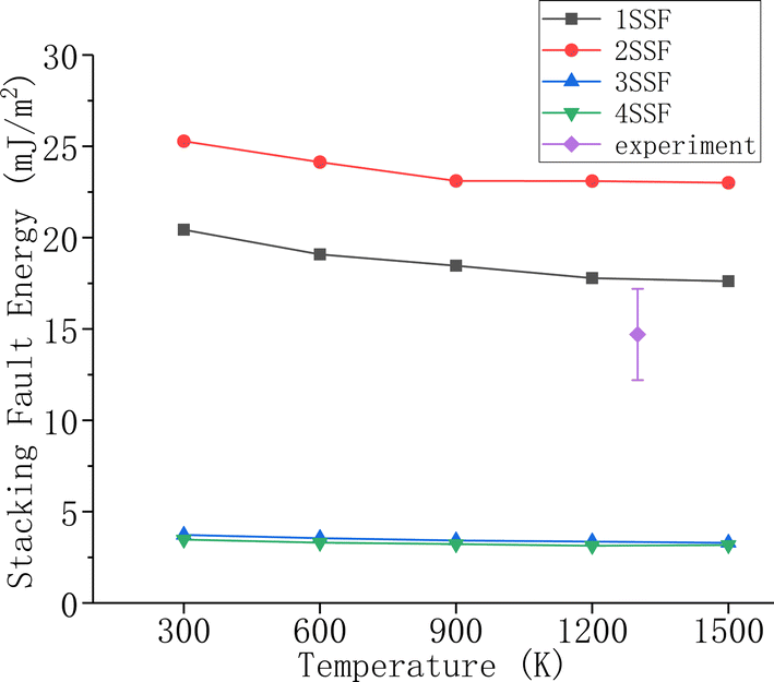
Fig. 5 shows the relationship between SFE and temperature (T). With T increasing, there is a notable decrease in the SFE of 1SSF and 2SSF, and this decrease tends to stabilize after T reaches 1200 K. In contrast, the SFE of 3SSF and 4SSF exhibits minimal variations with T. Consequently, it can be inferred that SFE exhibits limited dependence on T. Fig. 5 also shows the experimental data.53 Notably, there is no variable control of the type of SSF in the experiment. Therefore, the experimental data is the result of the combined action of different SSF. The average SFE of the four SSF in this study is consistent with the experimental data, which proved the accuracy and correctness of this study.
 | ||
| Fig. 5 Relationship curve between stacking fault energy and temperature. | ||
3.2. Radiation displacement cascades
Fig. 6 shows time evolution of the number of defect in the displacement cascade of 4H-SiC with SSF, with a temperature of 300 K, with PKA-Si (EPKA = 8 KeV). The 4H-SiC with SSF exhibits formula rules, with CV + SiV = CI + SiI, and CV − CI = CSi − SiC, SiV − SiI = SiC − CSi when the number of defects is stable. Notably, the number of C-based defects (CV and CI) is more than that of Si-based defects (SiI and SiV), and SiC is more than CSi. Because the atomic mass and dislocation threshold energy of C is lower than those of Si,54,55 the formation energy of C-based defects is lower than that of Si-based defects, as documented in 56. Because of the diversity in formation energy, some Si sites are occupied by two C atoms simultaneously, which resulted in the defect quantity relationship mentioned above. Because the number of defects during stability satisfies CV + SiV = CI + SiI, the following analysis will focus on interstitial defects.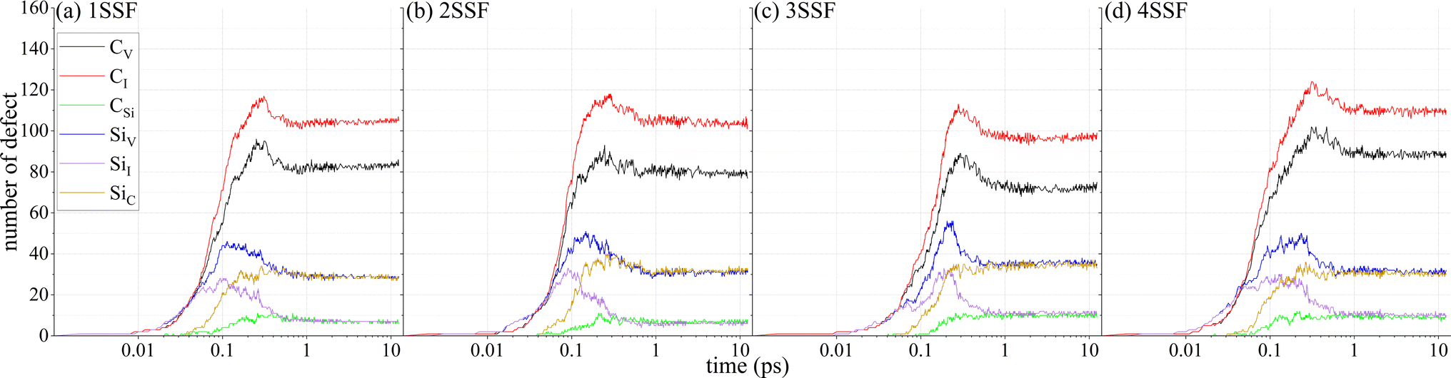 | ||
| Fig. 6 Time evolution of the number of defect in the displacement cascade of 4H-SiC with one (a) 1SSF, (b) 2SSF, (c) 3SSF, and (d) 4SSF. | ||
Fig. 7 shows time evolution of the number of interstitial defect and interstitial cluster in the displacement cascade of 4H-SiC, with a temperature of 300 K, with PKA-Si (EPKA = 8 KeV). 0SSF means the 4H-SiC without SSF. The number of defect and cluster undergoes a rapid initial growth, then reaches a peak at 0.2 ps ± 0.05 ps, and subsequently decreases to a stable value. It is worth noting that the peak value of the defect number of 4H-SiC with 4SSF is higher than that of 4H-SiC in other cases, and the peak occurs later. At the same time, the stable value of the defect number of 4H-SiC with 4SSF is also higher than that of 4H-SiC in other cases. The possible reason is that 4SSF causes 4H-SiC to exhibit overlapping stacking localities similar to 6H-SiC and 8H-SiC, and the energy hierarchy of SiC polytypes follows the order 2H > 3C > 4H > 6H > 8H.52
 | ||
| Fig. 7 Time evolution of the number of defect and cluster in the displacement cascade. | ||
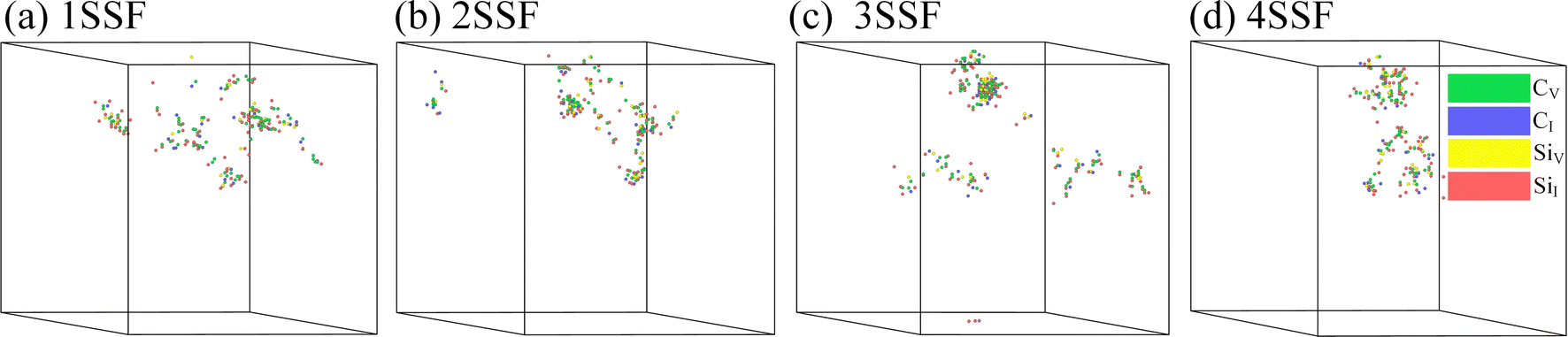
Fig. 8 shows the irradiation displacement cascade in 4H-SiC with SSF with a temperature of 300 K, with PKA-Si (EPKA = 8 KeV), at a certain simulation time of 10 ps. In Fig. 8(b), the defects on the left side of the model result from particle collisions on the right side, as our model adopts periodic boundary conditions. Consequently, defects penetrating the right side of the model are displayed on the left side. In Fig. 8(c), the gap defect appearing at the bottom of the model is formed by recoil particles generated upward following PKA particle collisions. This phenomenon is also a consequence of the periodic boundary conditions, causing upward-recoiled particles to manifest at the bottom.
 | ||
| Fig. 8 Irradiation displacement cascade in 4H-SiC with one (a) 1SSF, (b) 2SSF, (c) 3SSF, and (d) 4SSF. | ||
It can be seen that in 4H-SiC with SSF, the defects are mainly concentrated in the upper half, especially above the SSF, while no defects are observed below the SSF. To ensure the reliability of our research results, we conducted 30 repeated radiation displacement cascade simulations. Interestingly, not every repetition results in defects confined only above the SSF, and only 3 repetition groups showed this situation. We conducted 30 repeated radiation displacement cascade simulations on 4H-SiC without SSF. Contrary to what was observed in Fig. 8 (where defects concentrated in the upper half), this phenomenon did not occur in the displacement cascade in perfect 4H-SiC as shown in Fig. 9. As depicted in Fig. 9, the majority of defects in 4H-SiC without SSF accumulated in the upper half, and the minority of defects appeared in the lower half of 4H-SiC. In addition, we conducted 30 repeated irradiation displacement cascade simulations at 2 KeV, 4 KeV, 6 KeV and 10 KeV, respectively. We found that at 2 KeV, 4 KeV, and 6 KeV, there was one repetition group at each EPKA that showed the situation of defects concentrated in the upper half, and there were 2 repetition groups at 10 KeV that showed the situation of defects concentrated in the upper half. In conclusion, our findings confirm that SSF limits defect distribution position under certain specific conditions, which is consistent with the conclusion proposed in ref. 20 that the nano-engineered SiC with high-density stacking faults exhibits an increase in radiation resistance by more than an order of magnitude. However, the specific conditions and mechanisms of this hindrance and promotion of defect formation deserve further investigation.
 | ||
| Fig. 9 Irradiation displacement cascade in perfect 4H-SiC. | ||
3.3. Defects and clusters analysis
Fig. 10 shows the variation in the number of defects with incident depth, with PKA-Si (EPKA = 8 KeV), with a temperature of 300 K, at a certain simulation time of 10 ps. As shown in Fig. 10(a), the topmost atomic layer is at a depth of 0 Å, while the bottom atomic layer is at a depth of 200 Å. As we delve deeper into the material, the number of defects shows a three gradients growth pattern. The first gradient occurs at the depth of 20 Å ± 5 Å, the second gradient occurs at the depth of 40 Å ± 5 Å, and the third gradient occurs at the depth of 100 Å ± 5 Å. The first gradient exhibits a relatively short stopping depth, with an average of 4 Å, while the second gradient extends to a wider depth, with an average of 10 Å. At the third gradient, the number of defects reaches the maximum. 4H SiC without SSF has no gradient pattern, with the deepest depth at 170 Å. As shown in Fig. 10(b), no defects exist between the depth of 0 Å and 20 Å. Defects in 4H-SiC without SSF gradually reduces as the depth increases. The defects in 4H-SiC with 1SSF are mainly concentrated between the depth of 40 Å and 60 Å. The defects in 4H-SiC with 2SSF mainly concentrated between the depth of 20 Å and 60 Å. The defects in 4H-SiC with 3SSF mainly concentrated between the depth of 20 Å and 40 Å. The defects in 4H-SiC with 4SSF mainly concentrated between the depth of 20 Å and 40 Å. No defects exist between the depth of 180 Å and 200 Å. Except for the generation of 4 defects below the depth of 100 Å in 4H-SiC with 3SSF, no defects are produced below the depth of 100 Å in other 4H-SiC with SSF. | ||
| Fig. 10 Relationship between the number of defects and incident depth. (a) Curve between the number of defects and incident depth; (b) defect quantity within the range of every 20 Å. | ||
Fig. 11 shows the variation of the number of defects with EPKA, with PKA-Si, with a temperature of 300 K, at a certain simulation time of 10 ps. The effect of EPKA on the number of defects is obvious. As EPKA increases, the number of various point defects increases. The number of defects in 4H-SiC with 1SSF is similar to that in 4H-SiC without SSF. The number of defects in 4H-SiC with 3SSF is similar to that in 4H-SiC with 4SSF. The number of defects in 4H-SiC with SSF is higher than that in 4H-SiC without SSF which indicating that SSF will reduce the stability of 4H-SiC, thereby increasing the number of defects.
 | ||
| Fig. 11 Relationship curve between the number of defects and EPKA. | ||
Fig. 12 shows the variation of the number of interstitial defects with temperature, with PKA-Si (EPKA = 8 KeV), at a certain simulation time of 10 ps. In the temperature range of 300 K to 1200 K, 4H-SiC without SSF, 4H-SiC with 1SSF, and 4H-SiC with 2SSF are not significantly affected by temperature. The number of defects in 4H-SiC with 3SSF decreases slightly in the temperature range of 300 K to 900 K, while it significantly increases at a temperature of 1200 K. The number of defects in 4H-SiC with 4SSF gradually increases in the temperature range of 300 K to 1200 K, and the number of defects increases significantly at 1200 K. The max working temperature of 4H-SiC without SSF is 1240 K,57 so the number of defects in 4H-SiC without SSF will not change in the temperature range of 300 K to 1200 K. But the SSF resulted in a change in the maximum operating temperature that 4H SiC can withstand, leading to a change in the number of defects.
 | ||
| Fig. 12 Relationship curve between the number of defects and T. | ||
Fig. 13 shows the variation in the number of interstitial clusters with cluster size and EPKA, with PKA-Si, with a temperature of 300 K, at a certain simulation time of 10 ps. The maximum cluster size is 3 within the energy range of 10 KeV. Therefore, our analysis focuses on clusters with cluster sizes less than 4. The number of cluster increases as EPKA increases. In other words, higher EPKA results in more clusters. The number of cluster in 4H-SiC with SSF is higher than that in 4H-SiC without SSF, with the most significant difference observed at EPKA = 10 KeV. One possible reason is that SSF can affect the number of defects in 4H-SiC during radiation, which is consistent with the previous conclusion, leading to a change in the number of clusters. The second possible reason is that SSF can affect the distribution position of defects, making it easier for defects to gather together to form clusters.
 | ||
| Fig. 13 The number of interstitial clusters as a function of cluster size and EPKA. | ||
Fig. 14 shows the variation in the number of interstitial cluster with temperature, with PKA-Si (EPKA = 8 KeV), at a certain simulation time of 10 ps. Same as the effect of temperature on the number of defects, SSF leads to a change in the max working temperature of 4H-SiC. Therefore, the number of clusters increases significantly at 900 K and 1200 K. The effect of 3SSF and 4SSF on the number of cluster is greater than that of 1SSF and 2SSF on the number of clusters. The possible reason is that 1SSF results in overlapping stacking regions similar to 6H-SiC and 2H-SiC, 2SSF results in stacking regions similar to single 6H-SiC, 3SSF results in overlapping stacking localities similar to double 6H-SiC, 4SSF results in overlapping stacking localities similar to 6H-SiC and 8H-SiC.
 | ||
| Fig. 14 The number of interstitial clusters as a function of cluster size and T. | ||
4. Discussion
This study used molecular dynamics simulation method to investigate the effect of stacking faults on the radiation displacement cascade of 4H-SiC.Studies show that SSF can affect the distribution and number of defects and clusters in the radiation displacement cascade of 4H-SiC, as well as the temperature tolerance of 4H-SiC. The possible reason is that SSF causes changes in the 4H-SiC lattice, resulting in the local formation of 3C-SiC, 6H-SiC, and 8H-SiC. In other words, 4H-SiC is locally doped with other types of SiC. The energy hierarchy of SiC polytypes follows the order 2H > 3C > 4H > 6H > 8H,52 and the maximum working temperature of different types of SiC is different, so different SSF has different effects on 4H-SiC. And the properties of 4H-SiC and 6H-SiC are similar, as shown in Table 2,58–62 so the 4SSF that causes overlapping stacking localities similar to 6H-SiC and 8H-SiC has a greater effect on the radiation displacement cascade of 4H-SiC than the 3SSF that causes overlapping stacking localities similar to double 6H-SiC.
| Material | 4H-SiC | 6H-SiC | |
|---|---|---|---|
| Band gap | eV | 3.3 | 2.9 |
| Electron mobility | 103 cm2 V−1 s−1 | 1 | 0.5 |
| Electron saturation velocity | 107 cm s−1 | 2 | 2 |
| Breakdown field strength | MV cm−1 | 2.2 | 2.5 |
| Thermal conductivity | W cm−1 K−1 | 4.9 | 4.9 |
| Maximum operating temperature | 103 K | 1.24 | 1.58 |
Whatever, the effect of SSF on the radiation displacement cascade of 4H-SiC requires further study. The effect of SSF on the number of defects and the effect principle of SSF on the distribution location of defects still need further investigation. The maximum working temperature of 4H-SiC with SSF still needs more detailed calculation and determination.
5. Conclusion
In this work, we used the MD method to study the effects of SSF on the radiation displacement cascade of 4H-SiC. We analyzed the SFE of different SSF. The results showed that 2SSF has high stability, while 1SSF is relatively easier to form. 3SSF and 4SSF are the most easy to form. We analyzed the effect of SSF on the distribution of defects. The results showed that SSF limits defect distribution position, but the specific conditions and mechanisms of the limit behavior are worth further study. We analyzed the changes in the number of defects and clusters in the 4H-SiC with SSF under different EPKA and T conditions. The results showed that different SSF have different effect on the number of defects and clusters. The number of defects in 4H-SiC with SSF varies in the three gradients pattern with increasing incident depth. SSF causes structural changes within 4H-SiC, resulting in a change in the number of defects. The higher the EPKA, the more changes in the number of defects caused by SSF. SSF causes a change in the maximum working temperature of 4H-SiC, resulting in a higher number of defects at higher temperatures. SSF not only affects the number of defects, but also affects the distribution position of defects, leading to changes in the number of clusters. As EPKA increases, the number of clusters in 4H-SiC with SSF increases more than in 4H-SiC without SSF. Under the effect of SSF on the maximum working temperature of 4H-SiC, the increase in temperature causes a change in the number of clusters of 4H-SiC with SSF.In summary, this work analyzed the potential factors leading to different SFE of SSF. SSF limits defect distribution position. When the limit behavior occurs, the number of defects in 4H-SiC with SSF exhibits a three gradients growth pattern as a function of incident depth. SSF has an effect on the defects and clusters of 4H-SiC in displacement cascade, and it can affect the maximum working temperature of 4H-SiC.
Data availability
Data for this article are available at Science Data Bank [https://www.scidb.cn/en/s/aauyAb]. The code for LAMMPS can be found at https://www.lammps.org [S. Plimpton, A. Kohlmeyer, A. Thompson, S. Moore, R. Berger, 2021, LAMMPS Stable release 29 September 2021, 10.5281/zenodo.6386596]. The version of the code employed for this study is version lammps-2021. The code for OVITO can be found at https://www.ovito.org. The version of the code employed for this study is Version 3.6.0. The code for MATLAB can be found at https://ww2.mathworks.cn/products/matlab-home.html. The version of the code employed for this study is Version 2016.Conflicts of interest
The authors have no conflicts of interest to disclose.Acknowledgements
This work was supported by the Hunan Province Key Laboratory for Ultra-Fast Micro/Nano Technology and Advanced Laser Manufacture (Grant No. 2018TP1041) and by the Molecular Dynamics Simulation of Irradiation Damage of Doped 4H-SiC Project (No. CX20200943).References
- L. H. Karlsson, A. Hallén, J. Birch, L. Hultman and P. O. Å. Persson, Atomically resolved microscopy of ion implantation induced dislocation loops in 4H-SiC, Mater. Lett., 2016, 181, 325–327, DOI:10.1016/j.matlet.2016.06.013
.
- Y. Han, B.-S. Li, Z.-G. Wang, J.-X. Peng, J.-R. Sun, K.-F. Wei, C.-F. Yao, N. Gao, X. Gao, L.-L. Pang, Y.-B. Zhu, T.-L. Shen, H.-L. Chang, M.-H. Cui, P. Luo, Y.-B. Sheng, H.-P. Zhang, X.-S. Fang, S.-X. Zhao, J. Jin, Y.-X. Huang, C. Liu, D. Wang, W.-H. He, T.-Y. Deng, P.-F. Tai and Z.-W. Ma, H-ion Irradiation-induced Annealing in He-ion Implanted 4H-SiC, Chin. Phys. Lett., 2017, 34, 012801, DOI:10.1088/0256-307X/34/1/012801
- W. Li, L. Li, F. Wang, L. Zheng, J. Xia, F. Qin, X. Wang, Y. Li, R. Liu, D. Wang, Y. Pan and F. Yang, Passivation effects of phosphorus on 4H-SiC (0001) Si dangling bonds: A first-principles study, Chin. Phys. B, 2017, 26, 037104, DOI:10.1088/1674-1056/26/3/037104
- E. Igumbor, O. Olaniyan, R. E. Mapasha, H. T. Danga, E. Omotoso and W. E. Meyer, Induced defect levels of P and Al vacancy-complexes in 4H-SiC: A hybrid functional study, Mater. Sci. Semicond. Process., 2018, 89, 77, DOI:10.1016/j.mssp.2018.09.001
- L. L. Snead, Y. Katoh and T. Nozawa, Radiation effects in SiC and SiC–SiC, Compr. Nucl. Mater., 2012, 4, 215–240, DOI:10.1016/B978-0-08-056033-5.00093-8
- L. Nuckols, M. L. Crespillo, Y. Yang, J. Li, E. Zarkadoula, Y. Zhang and W. J. Weber, Effects of recoil spectra and electronic energy dissipation on defect survival in 3C-SiC, Materialia, 2021, 15, 101023, DOI:10.1016/j.mtla.2021.101023
- W. Weber and L. Wang, The temperature dependence of ion-beam-Induced amorphization in β-SiC, Nucl. Instrum. Methods Phys. Res., Sect. B, 1995, 106, 298–302, DOI:10.1016/0168-583X(95)00722-9
- L. L. Snead and J. C. Hay, Neutron irradiation induced amorphization of silicon carbide, J. Nucl. Mater., 1998, 273(2), 213–220, DOI:10.1016/S0022-3115(99)00023-9
- M. Ishimaru, I.-T. Bae and Y. Hirotsu, Electron-beam-induced amorphization in SiC, Phys. Rev. B: Condens. Matter Mater. Phys., 2003, 68, 144102, DOI:10.1103/PhysRevB.68.144102
- G. Lucas and L. Pizzagalli, Ab initio molecular dynamics calculations of threshold displacement energies in silicon carbide, Phys. Rev. B: Condens. Matter Mater. Phys., 2005, 72(16), 1202, DOI:10.1103/PhysRevB.72.161202
- F. Gao, H. Y. Xiao and W. Weber, Ab initio molecular dynamics simulations of low energy recoil events in ceramics, Nucl. Instrum. Methods Phys. Res., 2011, 269(14), 1693–1697, DOI:10.1016/j.nimb.2011.01.131
- F. Zhang, X. Chen, Y. Cui, L. Xiao and H. Xiao-Bo, Defects in Ge doped SiC crystals, J. Inorg. Mater., 2016, 31, 1166, DOI:10.15541/jim20160129
- B. Wang, T. Peng, J. Liang, G. Wang, W. Wang, H. Zhao and X. Chen, Characterizations and formation mechanism of a new type of defect related to nitrogen doping in SiC crystals, Appl. Phys. A: Solids Surf., 2014, 117, 1563–1569, DOI:10.1007/s00339-014-8594-x
- C. Liu, X. Chen, T. Peng, B. Wang, W. Wang and G. Wang, Step flow and polytype transformation in growth of 4H-SiC crystals, J. Cryst. Growth, 2014, 394, 126–131, DOI:10.1016/j.jcrysgro.2014.02.027
- S. Wei, S. Youting, L. Chunjun, P. Tonghua, W. Wenjun and C. Xiaolong, Basal plane dislocation-threading edge dislocation complex dislocations in 6H-SiC single crystals, Mater. Express, 2015, 5, 63–67, DOI:10.1166/mex.2015.1212
- R. Leonard, Y. Khlebnikov, A. Powell, C. Basceri, M. Brady, I. Khlebnikov, J. Jenny, D. Malta, M. Paisley and V. Tsvetkov, 100 mm 4HN-SiC wafers with zero micropipe density, Mater. Sci. Forum, 2008, 600–603, 7–10, DOI:10.4028/www.scientific.net/MSF.600-603.7
- Z. Ning, L. Chun-Jun, W. Bo and P. Tong-Hua, Stacking faults in 4H-SiC single crystal, J. Inorg. Mater., 2018, 33, 540, DOI:10.15541/jim20170300
- J. D. Caldwell, K. X. Liu, M. J. Tadjer, O. J. Glembocki, R. E. Stahlbush, K. D. Hobart and F. Kub, Thermal annealing and propagation of shockley stacking faults in 4H-SiC PiN diodes, J. Electron. Mater., 2007, 36, 318–323, DOI:10.1007/s11664-006-0038-8
- M. Camarda, A. L. Magna, P. Delugas and F. L. Via, First principles investigation on the modifications of the 4H-SiC band structure due to the (4,4) and (3,5) stacking faults, Appl. Phys. Express, 2011, 4, 417–423, DOI:10.1143/APEX.4.025802
- Y. Zhang, M. Ishimaru, T. Varga, T. Oda, C. Hardiman, H. Xue, Y. Katoh, S. Shannon and W. J. Weber, Nanoscale engineering of radiation tolerant silicon carbide, Phys. Chem. Chem. Phys., 2012, 14(38), 13429–13436, 10.1039/c2cp42342a
- L. Jamison, M. Zheng, S. Shannon, T. Allen, D. Morgan and I. Szlufarska, Experimental and ab initio study of enhanced resistance to amorphization of nanocrystalline silicon carbide under electron irradiation, J. Nucl. Mater., 2014, 445, 181–189, DOI:10.1016/j.jnucmat.2013.11.010
- S. Asada, K. Murata and H. Tsuchida, Limited current conduction due to various types of stacking faults in n-type 4H-SiC epilayers, Appl. Phys. Express, 2022, 15(4), 045502, DOI:10.35848/1882-0786/ac5c01
- E. Do, M. Kaneko and T. KIMOTO, Expansion patterns of single Shockley stacking faults from scratches on 4H-SiC, Jpn. J. Appl. Phys., 2021, 60, 068001, DOI:10.35848/1347-4065/abfc5e
- J. Nishio, A. Okada, C. Ota and R. Iijima, Direct confirmation of structural differences in single Shockley stacking faults expanding from different origins in 4H-SiC PiN diodes, J. Appl. Phys., 2020, 128, 085705, DOI:10.1063/5.0021764
- M. Camarda, P. Delugas, A. Canino, A. Severino, N. Piluso, A. L. Magna and F. L. Via, Systematic first principles calculations of the effects of stacking fault defects on the 4H-SiC band structure, Mater. Sci. Forum, 2010, 645, 283–286, DOI:10.4028/www.scientific.net/MSF.645-648.283
- G. Feng, J. Suda and T. Kimoto, Characterization of stacking faults in 4H-SiC epilayers by room-temperature microphotoluminescence mapping, Appl. Phys. Lett., 2008, 92, 221906, DOI:10.1063/1.2937097
- G. Feng, J. Suda and T. Kimoto, Triple shockley type stacking faults in 4H-SiC epilayers, Appl. Phys. Lett., 2009, 94, 091910, DOI:10.1063/1.3095508
- W. Choyke, H. Matsunami and G. Pensl, Silicon carbide: recent major advances, Mater. Today, 2004, 7, 57, DOI:10.1007/978-3-642-18870-1
- J. Bergman, H. Lendenmann, P. Nilsson, U. Lindefelt and P. Skytt, Crystal defects as source of anomalous forward voltage increase of 4H-SiC diodes, Mater. Sci. Forum, 2001, 353–356, 299–302, DOI:10.4028/www.scientific.net/MSF.353-356.299
- M. Skowronski and S. Ha, Degradation
of hexagonal silicon-carbide-based bipolar devices, J. Appl. Phys., 2006, 99, 11101, DOI:10.1063/1.2159578
- S. Izumi, H. Tsuchida, I. Kamata and T. Tawara, Structural analysis and reduction of in-grown stacking faults in 4H–SiC epilayers, Appl. Phys. Lett., 2005, 86, 749, DOI:10.1063/1.1927274
- H. Fujiwara, T. Kimoto, T. Tojo and H. Matsunami, Characterization of in-grown stacking faults in 4H–SiC (0001) epitaxial layers and its impacts on high-voltage Schottky barrier diodes, Appl. Phys. Lett., 2005, 87 DOI:10.1063/1.1997277
- J. SolTys, J. Piechota, P. Strak and S. Krukowski, Electronic charge transfer contribution in adsorption of silicon at the SiC(0001) surface—A density functional theory (DFT) study, Appl. Surf. Sci., 2017, 393, 168–179, DOI:10.1016/j.apsusc.2016.10.007
- S. Plimpton, Fast parallel algorithms for short-range molecular dynamics, J. Comput. Phys., 1995, 117, 1–19, DOI:10.1006/JCPH.1995.1039
- M. D. Mihai, D. Iancu, E. Zarkadoula, R. A. Florin, Y. Tong, Y. Zhang, W. J. Weber and G. Velis, Athermal annealing of pre-existing defects in crystalline silicon, Acta Mater., 2023, 261, 119379, DOI:10.1016/j.actamat.2023.119379
- E. Zarkadoula, Y. Zhang and W. J. Weber, Molecular dynamics simulations of the response of pre-damaged SrTiO3 and KTaO3 to fast heavy ions, AIP Adv., 2019, 10, 015019, DOI:10.1063/1.5133061
- E. Zarkadoula, G. Samolyuk and W. J. Weber, Effects of electron–phonon coupling on damage accumulation in molecular dynamics simulations of irradiated nickel, Mater. Res. Lett., 2019, 7, 490–495, DOI:10.1080/21663831.2019.1659435
- M. Kempner, J. M. Sestito, Y. Wang and E. Zarkadoula, Molecular dynamics simulations of cascade events in AlN, Results Mater., 2023, 17, 100383, DOI:10.1016/j.rinma.2023.100383
- Q. Ran, Y. Zhou, Y. Zou, J. Wang and S. Gao, Molecular dynamics simulation of displacement cascades in cubic silicon carbide, Nucl. Mater. Energy, 2021, 27, 100957, DOI:10.1016/j.nme.2021.100957
- R. Devanathan, T. D. d. l. Rubia and W. J. Weber, Displacement threshold energies in β-SiC, J. Nucl. Mater., 1998, 253, 47–52, DOI:10.1016/S0022-3115(97)00304-8
- W. Liao, C. He and H. He, Molecular dynamics simulation of displacement damage in 6H-SiC, Radiat. Eff. Defects Solids, 2019, 1042, 1029, DOI:10.1080/10420150.2019.1649260
- W. Li, L. Wang, L. Bian, F. Dong, M. Song, J. Shao, S. Jiang and H. Guo, Threshold displacement energies and displacement cascades in 4H-SiC: Molecular dynamic simulations, AIP Adv., 2019, 9, 055007, DOI:10.1063/1.5093576
- W. G. Hoover, Generalization of Nosé's isothermal molecular dynamics: Non-Hamiltonian dynamics for the canonical ensemble, Phys. Rev. A, 1989, 40, 2814, DOI:10.1103/PhysRevA.40.2814
- G. J. Martyna, D. J. Tobias and M. L. Klein, Constant pressure molecular dynamics algorithms, J. Chem. Phys., 1994, 101, 4177–4189, DOI:10.1063/1.467468
- V. Raineri, V. Privitera and S. U. Campisano, Channeling effects in ion implantation in silicon, Radiat. Eff. Defects Solids, 1994, 131, 399–413, DOI:10.1080/10420159408219799
- A. Stukowski, Visualization and analysis of atomistic simulation data with OVITO–the Open Visualization Tool, Modell. Simul. Mater. Sci. Eng., 2010, 18, 2154–2162, DOI:10.1088/0965-0393/18/1/015012
- S. Kettle and L. Norrby, The Wigner-Seitz unit cell, J. Chem. Educ., 1994, 71, 1003–1006, DOI:10.1021/ed071p1003
- G. Samolyuk, Y. Osetsky and R. Stoller, Molecular dynamics modeling of atomic displacement cascades in 3C–SiC: Comparison of interatomic potentials, J. Nucl. Mater., 2015, 465, 83–88, DOI:10.1016/j.jnucmat.2015.05.036
- H. Sakakima, S. Takamoto, A. Hatano and S. Izumi, Temperature-dependent stacking fault energies of 4H-SiC: A first-principles study, J. Appl. Phys., 2020, 127, 125703, DOI:10.1063/1.5141029
- H. Iwata, U. Lindefelt, S. Öberg and P. R. Briddon, Cubic polytype inclusions in 4H–SiC, J. Appl. Phys., 2003, 93, 1577–1585, DOI:10.1063/1.1534376
- U. Lindefelt, H. Iwata, S. Öberg and P. R. Briddon, Stacking faults in 3C-, 4H-, and 6H-SiC polytypes investigated by an ab initio supercell method, Phys. Rev. B: Condens. Matter Mater. Phys., 2003, 67, 155204, DOI:10.1103/PhysRevB.67.155204
- S. Limpijumnong and W. R. L. Lambrecht, Total energy differences between SiC polytypes revisited, Phys. Rev. B: Condens. Matter Mater. Phys., 1998, 57, 12017, DOI:10.1103/PhysRevB.57.12017
- M. H. Hong, A. V. Samant and P. Pirouz, Stacking fault energy of 6H-SiC and 4H-SiC single crystals, Philos. Mag. A, 2000, 80, 919–935, DOI:10.4028/www.scientific.net/MSF.338-342.513
- R. Devanathan, W. Weber and T. Rubia, Computer simulation of a 10 keV Si displacement cascade in SiC, Nucl. Instrum. Methods Phys. Res., Sect. B, 1998, 141, 118–122, DOI:10.1016/S0168-583X(98)00084-6
- E. Zarkadoula, G. Samolyuk, Y. Zhang and W. Weber, Electronic stopping in molecular dynamics simulations of cascades in 3C–SiC, J. Nucl. Mater., 2020, 540, 152371, DOI:10.1016/j.jnucmat.2020.152371
- P. Erhart and K. Albe, Analytical potential for atomistic simulations of silicon, carbon, and silicon carbide, Phys. Rev. B: Condens. Matter Mater. Phys., 2005, 71, 1–14, DOI:10.1103/PhysRevB.71.035211
- L. Torrisi, G. Foti, L. Giuffrida, D. Puglisi, J. Wolowski, J. Badziak, P. Parys, M. Rosinski, D. Margarone, J. Krasa, A. Velyhan and U. Ullschmied, Single crystal silicon carbide detector of emitted ions and soft x rays from power laser-generated plasmas, J. Appl. Phys., 2009, 105, 123304, DOI:10.1063/1.3153160
- B. J. Baliga, Trends in power semiconductor devices, IEEE Trans. Electron Devices, 1996, 43, 1717, DOI:10.1109/16.536818
- M. Kuzuhara, Nitride power devices:future perspectives, Int.RCIQE/CREST Joint Workshop, Hokkaido University, 2010, p. 1 Search PubMed
- H. OKUMURA, Present status and future prospect of widegap semiconductor high-power devices, Jpn. J. Appl. Phys., 2006, 45, 7565, DOI:10.1143/JJAP.45.7565
- F. Wang, F. Liu, J. Wang, Z. Lu and L. Wang, Review of diamond semiconductor devices, J. Wuhan Inst. Technol., 2020, 42, 518, DOI:10.19843/j.cnki.cn42-1779/tq.202002011
- H. Morkoc, S. Strite, G. B. Gao, M. E. Lin, B. Sverdlov and M. Burns, Large-band-gap SiC, III-V nitride, and II-VI ZnSe-based semiconductor device technologies, J. Appl. Phys., 1994, 76, 1363, DOI:10.1063/1.358463
| This journal is © The Royal Society of Chemistry 2024 |