 Open Access Article
Perfluoro-1-butanesulfonic acid etching strategy for dendrite suppression in aqueous zinc metal batteries†
Wanhao Chena,
Changhao Zhub,
Xinnan Xub and
Xuejun Liu*a
aCollege of Chemistry and Chemical Engineering, State Key Laboratory of Bio-fibers and Eco-textiles, Qingdao University, Qingdao 266071, China. E-mail: xjliu@qdu.edu.cn
bSchool of Chemistry and Chemical Engineering, Nantong University, Nantong 226019, China
First published on 13th June 2024
Abstract
Perfluoro-1-butanesulfonic acid (PFBS) was used to etch on the surface of a zinc anode to introduce a 3D C4F9O3S–Zn interface layer with unique fluorine groups (Zn@PFBS) to inhibit the formation of dendrites. The C–F chains in the Zn@PFBS coating enhance the anode hydrophobicity of the zinc metal, which not only suppresses the HER of the surface of the zinc metal, but also strengthens the corrosion resistance of the zinc metal. Meanwhile, –SO3− in the coating enhanced the binding energy with Zn2+, which acted as a nucleation site on the surface of the zinc anode to induce the uniform deposition of Zn2+ and inhibited the disordered growth of zinc dendrites. As a result, the symmetric battery assembled with the Zn@PFBS anode achieved a stable cycling of 6200 cycles at 5 mA cm−2 to 1 mA h cm−2. Meanwhile, the Zn@PFBS anode exhibited a higher cycling performance with a capacity retention rate of 78.6% after 1000 cycles in a Zn@PFBS//Na5V12O32 (NVO) full cell.
Introduction
The rapid expansion of renewable energy sources like wind and solar energy, which are characterized by intermittency and widespread distribution, necessitate an electrochemical energy storage system that ensures high safety and low cost to guarantee their sustainable development irrespective of factors like climate and geographical location.1–6 Presently, due to the ongoing advancements in lithium-ion battery technology, they have become the primary energy storage devices owing to their high energy density and efficient charging and discharging capabilities.7–11 However, limited by the scarce natural reserves of lithium metal and its high prices, lithium-ion batteries incur relatively high costs and pose additional safety hazards, including toxic organic electrolytes.12–14 Overcharging, over-discharging, or short-circuiting may result in battery thermal runaway and subsequent spontaneous combustion, along with other safety concerns, thereby limiting the large-scale commercialization of lithium batteries for energy storage.15–17 To address these challenges effectively, an urgent necessity exists to discover alternative battery technologies to replace the current lithium-ion battery-based energy storage systems.18–20In this context, researchers highly favor aqueous zinc metal batteries (AZMBs) due to their low redox potential (−0.76 V vs. SHE), high theoretical and volumetric capacities (820 mA h g−1 and 5855 mA h cm−3), non-toxicity, high safety, and affordability.21–23 However, AZMBs also encounter a series of challenges, including disordered dendrite growth, corrosion, and hydrogen precipitation, which finally reduce the reversibility of zinc anodes, diminish their rechargeability, and thereby impair the cycle life, hindering their large-scale commercial application.24–26 To mitigate issues arising from zinc dendrites, several strategies have been proposed aiming to achieve high reversibility and prolonged cycling of zinc anodes, such as the construction of an interfacial coating, zinc alloying, the utilization of highly concentrated/gel electrolytes, and the employment of electrolyte additives.27–30 Among these strategies, constructing a suitable protective interface proves to be a simple and efficient method to modulate the interaction between the zinc anode and the electrolyte, probably due to its ease of preparation and affordability. This interface layer could prevent the direct contact between the electrolyte and the zinc anode, reduces the hydrogen evolution reaction (HER), and inhibit short circuits caused by zinc dendrites spiking the separator.31–33
However, conventional artificial interface layers exhibit several issues: instability during battery charging and discharging, the occurrence of interface layer rupture and reorganization, thereby increasing internal resistance and impacting cycle life; inadequate electrolyte penetration leading to uneven Zn2+ transmission and deposition, exacerbating zinc dendrite growth; high interfacial impedance, affecting Zn2+ transmission efficiency and battery charging efficiency.34–36 This impacts Zn2+ transmission efficiency and reduces battery charging and discharging efficiency.37–39 In contrast to conventional artificial interface layers, in situ generated layers offer remarkable advantages in AZMBs.40 Firstly, in situ generated interfaces offer stability during long-term battery cycling, minimizing interface layer rupture and dendrite growth. Additionally, the battery has a lower interfacial impedance, enhancing charging, discharging efficiency, and energy density, while simplifying battery preparation and reducing production costs.41–44 Moreover, the 3D porous structure of in situ generated layers provides a larger specific surface area, improving Zn2+ transport efficiency and electrolyte contact and resulting in the promotion of homogeneous zinc deposition.45–47 Nevertheless, the augmented specific surface area of the 3D structure amplifies water–zinc contact and enhances hydrogen precipitation reaction, significantly weaking battery life.48–50
Here, perfluoro-1-butanesulfonic acid (PFBS) with hydrophobic long fluorocarbon chains (C–F) and –SO3− was selected. The Zn–C4F9O3S interface layer (Zn@PFBS) was obtained by modifying the surface of the zinc anode through in situ etching of the zinc anode in solution to form a 3D interface layer. The C–F in the Zn@PFBS coating enhances the hydrophobicity of the zinc metal anode, inhibiting the HER and enhancing the corrosion resistance of the zinc anode.51 Meanwhile, the –SO3− in the coating, acts as the nucleation sites on the zinc anode, could increase the binding energy with Zn2+, promote the uniform Zn2+ deposition and suppress the disordered growth of zinc dendrites.52,53 The symmetric cell Zn@PFBS//Zn@PFBS demonstrated stable cycling performance, achieving 6200 cycles at 5 mA cm−2 to 1 mA h cm−2. And the assembled full-cell Zn@PFBS//Na5V12O32 (NVO) exhibited high-capacity retention of 78.6% over 1000 cycles at 2 A g−1, indicating superior cycling performance.
Results and discussion
This study aimed to form Zn@PFBS, an interface layer hydrophobic and favorable to zinc, through in situ etching of the zinc anode with PFBS solution and the introduction of unique fluorine groups to the interface layer. The hydrophobic nature of PFBS's polyfluoroalkyl chains requires additional energy for water molecules to penetrate the adsorption layer on the zinc anode. This property inhibits the HER at the zinc-anode, consequently suppressing the growth of zinc dendritic crystals, facilitating Zn2+ uniform deposition on the anode and significantly enhancing battery performance. As shown in Fig. 1a, the structure of PFBS and the reaction equation with the zinc anode is illustrated. The bare zinc anode depicts the situations where hydrogen precipitation and disordered dendritic growth impede the uniform Zn2+ deposition (Fig. 1b). Conversely, the Zn@PFBS interface layer not only prevents contact between H2O and the zinc anode but also promotes uniform Zn2+ deposition, leading to a stable and dendrite-free growth of the anode interface during cycling (Fig. 1c).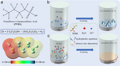 | ||
| Fig. 1 Schematic diagram (a) structure of PFBS; (b) cycling process diagram of bare zinc; (c) cycling process diagram of zinc surface after PFBS etching. | ||
Furthermore, the interface of the etched Zn@PFBS was examined and analyzed to determine the successful etching of PFBS on the zinc anode. The morphology of both the pure Zn foil and the 3D porous Zn foil etched with PFBS solution was characterized and displayed in Fig. S1.† Fig. S1a† demonstrated the SEM observation of the surface of pure Zn foil after cleaning with ethanol, which revealed an inhomogeneous and dense surface. In contrast, after soaking the zinc foil in PFBS solution for in situ etching, the Zn@PFBS showed the uniformly distributed porous structure on its surface (Fig. S1c†). Fig. S1d† demonstrated that the thickness of the Zn@PFBS interface is 23.65 μm.
| Zn + 2C4F9O3SH → Zn(C4F9O3S)2 + H2↑ | (1) |
Additionally, as chemical formula (1), the dissociated protons in the PFBS solution can be displaced by the Zn, leading to hydrogen generation. The energy dispersive spectrometer (EDS) test revealed the uniform distribution of F, S, C, and O on the surface of the PFBS-treated Zn foil (Fig. S2†). Moreover, the successful introduction of C–F and –SO3− on the zinc surface was confirmed using X-ray photoelectron spectroscopy (XPS), revealing two spectra: F 1s and S 1s (Fig. S3a and b†). These spectra demonstrate the alterations in the chemical state of the surface after the PFBS etching treatment. Examination of these spectrograms reveals distinct peaks in both the F 1s and S 1s spectra, confirming the successful introduction of fluorine and sulfur atoms on the material surface, thus confirming the effectiveness of the PFBS etching process.
The effect of in situ PFBS etching on the hydrogen precipitation reaction was further investigated. Initially, in situ optical microscopy was employed to explore the Zn deposition process at various time intervals. When discharging at a current of 10 mA cm−2, the dendrite growth can observe within 10 minutes, followed by further continuous growth and the formation of gas bubbles (Fig. 2a). Conversely, the Zn@PFBS interface consists of the hydrophobic layers of polyfluoroalkyl chains, requiring additional energy for water molecules to penetrate the adsorption layer on the surface of the zinc anode. This significantly inhibits water-related HER side reactions at the zinc anode (Fig. 2b). Consequently, during constant current discharge, no H2 bubble generation was observed on the surface of Zn@PFBS, while Zn2+ deposition was uniform and slow, effectively inhibiting dendrites growth and illustrating the clear suppression of the hydrogen precipitation reaction by the Zn@PFBS interface layer.
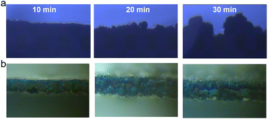 | ||
| Fig. 2 In situ optical microscopy observations at a current density of 10 mA cm−2 (a) bare Zn (b) Zn@PFBS. | ||
Subsequently, we conducted linear scanning voltammetry (LSV) in 2 M ZnSO4 to investigate the HER of Zn@PFBS electrode at a scanning rate of 1 mV s−1. Fig. S4† illustrates that the current density of Zn@PFBS (0.0058 mA cm−2) is lower than that of the bare zinc anode (0.033 mA cm−2), as evident from the HER curve. According to the LSV results, the prevention of water molecules from entering the surface and the significant suppression of harmful interfacial reactions are observed.
Additionally, hydrogen precipitation during galvanization tests was detected using in situ electrochemical gas chromatography (EC-GC). As shown in Fig. 3a, a sealed electrolytic cell comprising two electrodes (Zn as the positive electrode and Zn@PFBS as the anode), an inlet tube for nitrogen inflow, and an outlet tube for hydrogen outflow to the gas chromatograph was designed for in situ EC-GC measurements (Fig. 3a). Hydrogen generated from the zinc reaction process was analyzed by gas chromatography at 6 minute intervals under a current of 2.5 mA cm−2 (Fig. 3b). The average rate of H2 generation in cells using bare Zn is 2.01 μg h−1, whereas in the Zn@PFBS foil system, it is only 0.51 μg h−1, representing a quarter of the former value (Fig. 3c). The in situ EC-GC results provided the additional confirmation of the Zn@PFBS interface's ability to suppress hydrogen precipitation. These findings indicated the hydrophobic nature of Zn@PFBS, which could mitigate the direct contact with the electrolyte and suppress water-induced side reactions.
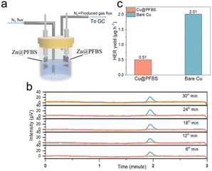 | ||
| Fig. 3 (a) Schematic diagram and (b) time-voltage curve from in situ EC-GC measurements; (c) H2 generation rate. | ||
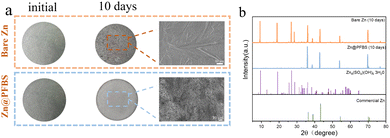
To evaluate the corrosion resistance of the interface, two different zinc anodes were immersed in a 2 M ZnSO4 solution, and their corrosion behavior was assessed after 10 days. Optical photographs revealed a smooth texture with a bright metallic luster on the surface of bare Zn before immersion, whereas the Zn@PFBS anode exhibited a black etching layer (Fig. 4a). Following 10 days of immersion, the bare Zn surface exhibited significant roughening, forming stacked, heterogeneous hexahedral flakes observed by SEM. Conversely, no significant changes could be observed on the surface of Zn@PFBS anode. X-ray diffraction (XRD) analysis revealed that the main chemical composition of the anode was Zn4SO4(OH)6·3H2O.54 The intensity of the by-products on the bare Zn anode was significantly higher than that on the Zn@PFBS anode, indicating the stronger corrosion protection effect of the PFBS layer (Fig. 4b). Furthermore, Tafel curves of bare Zn and Zn@PFBS anodes were further tested (Fig. S5†). Compared with bare Zn, PFBS etching improved the corrosion potential with a more positive value, indicating a reduced tendency for corrosion reaction, further demonstrating the superior corrosion resistance of the Zn@PFBS interface.
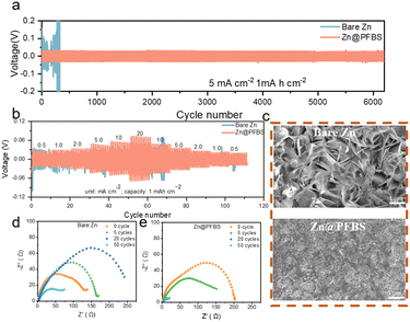
To evaluate the cycling performance of zinc anodes at various current densities, symmetric cells were assembled using Zn@PFBS and bare Zn anodes.55 As shown in Fig. 5a, the Zn@PFBS symmetric cell exhibited excellent cycling capability compared to bare Zn at a current density of 5 mA cm−2. The Zn@PFBS anode demonstrated a superior cycling stability of 6200 cycles with a capacity of 1 mA h cm−2 at 5 mA cm−2, exhibiting a lower overpotential of 0.04 V. Conversely, the overpotential of the bare Zn-based symmetric cells increased dramatically (above 0.2 V) after 300 cycles. In addition, we varied the current density to test symmetric cells with different anodes at a capacity of 0.1 mA h cm−2 under 0.5 mA cm−2. The Zn@PFBS//Zn@PFBS cells could still maintain the stable cycling for 1800 cycles (Fig. S6†), whereas the bare Zn//Zn cells could no longer maintain stable cycling after 400 cycles. These results confirm the superior electrochemical reversibility of the in situ etched Zn@PFBS anode and its excellent long-term cycling performance.
Furthermore, Zn@PFBS and bare Zn symmetric cells were tested at various current densities of 0.5, 1, 2, 5, 10 and 20 mA cm−2 to investigate the rate performance (Fig. 5b). The Zn@PFBS symmetric cells exhibit smaller and more stable overpotentials compared to bare Zn. The stable overpotentials of the Zn@PFBS symmetric cells can be attributed to the 3D interface formed by the etching of the zinc anode with PFBS, resulting in an increase in the electrochemical surface area and a decrease in the interfacial resistance. To explore the effect of different etching times, various interface layers of Zn@PFBS were obtained by etching in a 10 wt% PFBS solution for different durations (0.5 h, 3 h, and 18 h). The performance of the Zn@PFBS//Zn@PFBS symmetric cell was evaluated at the identical current density of 5 mA cm−2. As shown in Fig. S7,† the 3 h etching results in the high cycling stability of up to 6200 cycles, as the 3D interface layer enhances the contact area between water and zinc, favoring the uniform deposition of zinc ions. Conversely, when the immersion time is only 0.5 h, the interface layer is thin and structurally unstable, making it prone to hydrogen precipitation reaction, resulting in 1900 cycles; whereas with an etching time as high as 18 h, the interface layer becomes excessively thick, leading to decreased Zn2+ conductivity and significantly increased overpotential, resulting in only 700 cycles.
To comprehensively understand the superior stability of the Zn@PFBS anode, we comparatively analyzed the surface morphology of the anode after cycling using SEM characterization. After 100 cycles at 5 mA cm−2 to mA h cm−2, the bare Zn anode exhibited numerous vertically arranged hexagonal Zn dendrites with fractured and irregular surfaces. In contrast, the surface of the Zn@PFBS anode appeared to be dense and uniform after cycling (Fig. 5c). These results indicate that the PFBS etching layer plays a crucial role in promoting dense Zn deposition and inhibiting Zn dendrite growth. The Nyquist diagram, with the high-frequency semicircle representing the charge transfer resistance (Rct), is shown in Fig. 5d and e. The EIS plot of the bare Zn symmetric cell in Fig. 5d clearly shows a significant change in Rct before and after different cycles, with no regularity in Rct as the number of cycles increases, whereas in Fig. 5e the Rct of the Zn@PFBS symmetric cell decreases gradually and remains stable as the number of cycles increases. Chronoamperometry (CA) measurement is also conducted on the Zn//Zn symmetric cells with and without PFBS (Fig. S8†). The linear current increase curve of bare Zn shows a 2D diffusion process and inhomogeneous growth of dendrites due to the “tip effect”. In contrast, the 2D diffusion process ends within 20 s for Zn@PFBS and then a stable 3D diffusion occurs in the subsequent process with a much lower steady-state current. The enhanced Zn2+ reaction kinetics and remarkable corrosion resistance of the Zn@PFBS anode would contribute to highly reversible Zn plating/stripping. Overall, these results demonstrate the stability of the Zn@PFBS anode during cycling. It is worth noting that the experimental parameters tested in different literature vary greatly, including current density, capacity plated per cycle, and cycle number, resulting in an unfair comparison of battery performance. Therefore, the cumulative plated capacity (CPC) is proposed as an indicator for accurately evaluating the battery performance to prove the material superiority.56 For comparison, we summarize the CPC and current densities of recently reported aqueous Zn//Zn symmetric cells with similar interfacial modification mechanism.57–61 As shown in Fig. S9,† the battery using Zn@PFBS could achieve a higher CPC of 6 A h cm−2 at a current density of 5 mA cm−2, comparable or even superior to most reported CPC values.
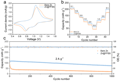
To examine the redox reactions and reversibility of the full cells, cyclic voltammetry (CV) tests were conducted on Zn@PFBS//NVO and bare Zn//NVO full cells (Fig. 6a). The comparison of redox peaks revealed that the voltage gap on the CV curve of the Zn@PFBS full cell at 0.1 mV s−1 was smaller than that of the bare Zn-based cell. Furthermore, the excellent rate capacities of the Zn@PFBS//NVO full cell at various current densities (0.1–5.0 A) were 217.7, 176.6, 133.9, 120, 98.7, and 64.3 mA h g−1, in comparison to that of the bare Zn//NVO full cell (198.4, 164.4, 122.6, 116.8, 82.2, and 45.4 mA h g−1) can be observed in Fig. 6b. It is evident that the Zn@PFBS-assembled full cells demonstrate higher discharge capacities across different current densities. In addition, the Zn@PFBS//NVO full cell showed excellent cycling performance at a current density 2 A g−1, maintaining the capacity retention of 78.6% and nearly 100% CE after 1000 cycles (Fig. 6c). In contrast, the bare Zn//NVO full cell exhibited rapid capacity degradation after approximately 50 cycles. Based on the charge/discharge curves for different anodes, it can be observed the bare Zn//NVO has a capacity retention of only 18.1% after 1000 cycles (Fig. S10†), in contrast to the Zn@PFBS//NVO full cells, which has a capacity of 78.6%. This enhancement in rate and cycling performance underscores the significant value of the Zn@PFBS anode in the practical application of full AZMBs batteries.
Conclusions
The utilization of acid etching in zinc batteries has emerged as a promising strategy to address critical challenges such as dendrite growth and hydrogen precipitation on the zinc anode. Through a meticulous process of in situ etching, an ultrathin Zn@PFBS interface layer is formed on the zinc foil surface. This interface layer, enriched with unique fluorine groups, enhances the hydrophobicity of the zinc anode, effectively suppressing the HER and enhancing corrosion resistance. Moreover, the interface layer facilitates the uniform deposition of Zn2+ and inhibits the disordered growth of zinc dendrites. The results show remarkable improvements in battery performance, including stable cycling behavior and high-capacity retention over numerous cycles. In addition, the Zn@PFBS//Zn@PFBS symmetric cell had a stable cycling performance of 6200 cycles at 5 mA cm−2 and 1 mA h cm−2. Meanwhile, the assembled full-cell Zn@PFBS//NVO also exhibited a high-capacity retention of 78.6% after 1000 cycles at 2 A g−1. The successful application of acid etching in zinc batteries showcases its potential to revolutionize the field, paving the way for the development of more efficient and durable energy storage systems.Data availability
The data supporting this article have been included as part of the ESI.†Conflicts of interest
There are no conflicts to declare.Acknowledgements
We acknowledge support from the National Natural Science Foundation of China (grant number 52002195), Science and Technology Project of Nantong (grant number JC12022047).Notes and references
- N. Nitta, F. Wu, J. T. Lee and G. Yushin, Mater. Today, 2015, 18, 252–264 CrossRef CAS.
- P. Yi, Y. Song, Z. Liu, G. Liang, R. Liu, L. Chen and J. Sun, Adv. Compos. Hybrid Mater., 2023, 6, 228 CrossRef CAS.
- P. Yi, Y. Song, C. Li, R. Liu and J. Sun, Appl. Surf. Sci., 2023, 619, 156789 CrossRef CAS.
- Y. Li, Z. Wang, Y. Cai, M. E. Pam, Y. Yang, D. Zhang, Y. Wang and S. Huang, Energy Environ. Mater., 2022, 5, 823–851 CrossRef CAS.
- J. Wang, L. Yin, H. Jia, H. Yu, Y. He, J. Yang and C. W. Monroe, ChemSusChem, 2014, 7, 563–569 CrossRef CAS PubMed.
- J. Zhu, L. Hu, P. Zhao, L. Y. S. Lee and K.-Y. Wong, Chem. Rev., 2020, 120, 851–918 CrossRef CAS PubMed.
- L. Lu, X. Han, J. Li, J. Hua and M. Ouyang, J. Power Sources, 2013, 226, 272–288 CrossRef CAS.
- A. Tomaszewska, Z. Chu, X. Feng, S. O'Kane, X. Liu, J. Chen, C. Ji, E. Endler, R. Li, L. Liu, Y. Li, S. Zheng, S. Vetterlein, M. Gao, J. Du, M. Parkes, M. Ouyang, M. Marinescu, G. Offer and B. Wu, Etransportation, 2019, 1, 100011 CrossRef.
- M. Li, J. Lu, Z. Chen and K. Amine, Adv. Mater., 2018, 30, 1800561 CrossRef PubMed.
- P. Lyu, X. Liu, J. Qu, J. Zhao, Y. Huo, Z. Qu and Z. Rao, Energy Storage Mater., 2020, 31, 195–220 CrossRef.
- J. Wang, P. Nie, G. Xu, J. Jiang, Y. Wu, R. Fu, H. Dou and X. Zhang, Adv. Funct. Mater., 2018, 28, 1704808 CrossRef.
- X. Bai, Y. Nan, K. Yang, B. Deng, J. Shao, W. Hu and M. Pu, Adv. Funct. Mater., 2023, 2307595 CrossRef CAS.
- S. Tan, Y. Jiang, S. Ni, H. Wang, F. Xiong, L. Cui, X. Pan, C. Tang, Y. Rong and Q. An, Natl. Sci. Rev., 2022, 9, nwac183 CrossRef CAS PubMed.
- G. Chen, Y. Kang, H. Yang, M. Zhang, J. Yang, Z. Lv, Q. Wu, P. Lin, Y. Yang and J. Zhao, Adv. Funct. Mater., 2023, 2300656 CrossRef CAS.
- X. Fan, X. Ji, L. Chen, J. Chen, T. Deng, F. Han, J. Yue, N. Piao, R. Wang, X. Zhou, X. Xiao, L. Chen and C. Wang, Nat. Energy, 2019, 4, 882–890 CrossRef CAS.
- D. Chen, M. Lu, D. Cai, H. Yang and W. Han, J. Energy Chem., 2021, 54, 712–726 CrossRef CAS.
- S. Chu, Y. Cui and N. Liu, Nat. Mater., 2017, 16, 16–22 CrossRef PubMed.
- J. Wang, B. Zhang, Z. Cai, R. Zhan, W. Wang, L. Fu, M. Wan, R. Xiao, Y. Ou and L. Wang, Sci. Bull., 2022, 67, 716–724 CrossRef CAS PubMed.
- J. Zhou, Y. Wang, J. Wang, Y. Liu, Y. Li, L. Cheng, Y. Ding, S. Dong, Q. Zhu and M. Tang, Energy Storage Mater., 2022, 50, 47–54 CrossRef.
- J. Zhou, Y. Ding, Y. Wang, H. Li, J. Shang, Y. Cao and H. Wang, J. Colloid Interface Sci., 2024, 657, 502–510 CrossRef CAS PubMed.
- T. Yamamoto and T. Shoji, Inorg. Chim. Acta, 1986, 117, L27–L28 CrossRef CAS.
- M. Pasta, C. D. Wessells, N. Liu, J. Nelson, M. T. McDowell, R. A. Huggins, M. F. Toney and Y. Cui, Nat. Commun., 2014, 5, 3007 CrossRef PubMed.
- L. Chen, Y. Ruan, G. Zhang, Q. Wei, Y. Jiang, T. Xiong, P. He, W. Yang, M. Yan, Q. An and L. Mai, Chem. Mater., 2019, 31, 699–706 CrossRef CAS.
- L. Ma, S. Chen, C. Long, X. Li, Y. Zhao, Z. Liu, Z. Huang, B. Dong, J. A. Zapien and C. Zhi, Adv. Energy Mater., 2019, 9, 1902446 CrossRef CAS.
- Q. Yang, G. Liang, Y. Guo, Z. Liu, B. Yan, D. Wang, Z. Huang, X. Li, J. Fan and C. Zhi, Adv. Mater., 2019, 31, 1903778 CrossRef CAS PubMed.
- Y. Shi, Y. Chen, L. Shi, K. Wang, B. Wang, L. Li, Y. Ma, Y. Li, Z. Sun, W. Ali and S. Ding, Small, 2020, 16, 2000730 CrossRef CAS PubMed.
- H. Li, L. Ma, C. Han, Z. Wang, Z. Liu, Z. Tang and C. Zhi, Nano Energy, 2019, 62, 550–587 CrossRef CAS.
- J. Yang, R. Zhao, Y. Wang, Z. Hu, Y. Wang, A. Zhang, C. Wu and Y. Bai, Adv. Funct. Mater., 2023, 33, 2213510 CrossRef CAS.
- Q. Zhang, J. Luan, Y. Tang, X. Ji and H. Wang, Angew. Chem., Int. Ed., 2020, 59, 13180–13191 CrossRef CAS PubMed.
- G.-L. Liu, T. Zhang, X.-J. Li, R.-P. Cao, J.-K. Shen, D.-L. Guo, N.-T. Wu, W.-W. Yuan, A. Cao and J. Liu, Rare Metals, 2023, 1–12 CrossRef.
- A. Konarov, N. Voronina, J. H. Jo, Z. Bakenov, Y.-K. Sun and S.-T. Myung, ACS Energy Lett., 2018, 3, 2620–2640 CrossRef CAS.
- X. Zhang, J. P. Hu, N. Fu, W. B. Zhou, B. Liu, Q. Deng and J. Wu, InfoMat, 2022, 4, e12306 CrossRef CAS.
- C. Zhu, J. Zhou, Z. Wang, Y. Zhou, X. He, X. Zhou, J. Liu, C. Yan and T. Qian, Chem. Eng. J., 2023, 454, 140413 CrossRef CAS.
- Z. Cai, Y. Ou, J. Wang, R. Xiao, L. Fu, Z. Yuan, R. Zhan and Y. Sun, Energy Storage Mater., 2020, 27, 205–211 CrossRef.
- Z. H. Yi, G. Y. Chen, F. Hou, L. Q. Wang and J. Liang, Adv. Energy Mater., 2021, 11 Search PubMed.
- Q. Zhang, Y. Ma, Y. Lu, X. Zhou, L. Lin, L. Li, Z. Yan, Q. Zhao, K. Zhang and J. Chen, Angew. Chem., Int. Ed., 2021, 133, 23545–23552 CrossRef.
- W. J. Lu, C. X. Xie, H. M. Zhang and X. F. Li, ChemSusChem, 2018, 11, 3996–4006 CrossRef CAS PubMed.
- C. Xie, Y. Li, Q. Wang, D. Sun, Y. Tang and H. Wang, Carbon Energy, 2020, 2, 540–560 CrossRef CAS.
- Z. W. Seh, J. Kibsgaard, C. F. Dickens, I. Chorkendorff, J. K. Nørskov and T. F. Jaramillo, Science, 2017, 355, eaad4998 CrossRef PubMed.
- Y. Chai, X. Xie, Z. He, G. Guo, P. Wang, Z. Xing, B. Lu, S. Liang, Y. Tang and J. Zhou, Chem. Sci., 2022, 13, 11656–11665 RSC.
- W. Xu, K. Zhao, W. Huo, Y. Wang, G. Yao, X. Gu, H. Cheng, L. Mai, C. Hu and X. Wang, Nano Energy, 2019, 62, 275–281 CrossRef CAS.
- Q. Zhang, J. Luan, L. Fu, S. Wu, Y. Tang, X. Ji and H. Wang, Angew. Chem., Int. Ed., 2019, 58, 15841–15847 CrossRef CAS PubMed.
- W. Du, E. H. Ang, Y. Yang, Y. Zhang, M. Ye and C. C. Li, Energy Environ. Sci., 2020, 13, 3330–3360 RSC.
- Q. Yang, Y. Guo, B. Yan, C. Wang, Z. Liu, Z. Huang, Y. Wang, Y. Li, H. Li and L. Song, Adv. Mater., 2020, 32, 2001755 CrossRef CAS PubMed.
- H. Dong, X. Hu, R. Liu, M. Ouyang, H. He, T. Wang, X. Gao, Y. Dai, W. Zhang and Y. Liu, Angew. Chem., Int. Ed., 2023, e202311268 CAS.
- J. Wu, C. Yuan, T. Li, Z. Yuan, H. Zhang and X. Li, J. Am. Chem. Soc., 2021, 143, 13135–13144 CrossRef CAS PubMed.
- W. Wang, G. Huang, Y. Wang, Z. Cao, L. Cavallo, M. N. Hedhili and H. N. Alshareef, Adv. Energy Mater., 2022, 12, 2102797 CrossRef CAS.
- Y. Zeng, X. Zhang, R. Qin, X. Liu, P. Fang, D. Zheng, Y. Tong and X. Lu, Adv. Mater., 2019, 31, 1903675 CrossRef PubMed.
- S.-B. Wang, Q. Ran, R.-Q. Yao, H. Shi, Z. Wen, M. Zhao, X.-Y. Lang and Q. Jiang, Nat. Commun., 2020, 11, 1634 CrossRef CAS PubMed.
- P. Liang, J. Yi, X. Liu, K. Wu, Z. Wang, J. Cui, Y. Liu, Y. Wang, Y. Xia and J. Zhang, Adv. Funct. Mater., 2020, 30, 1908528 CrossRef CAS.
- X. Fu, G. Li, X. Wang, J. Wang, W. Yu, X. Dong and D. Liu, J. Energy Chem., 2024, 88, 125–143 CrossRef CAS.
- Y. Lin, Y. Li, Z. Mai, G. Yang and C. Wang, Adv. Energy Mater., 2023, 13, 2301999 CrossRef CAS.
- K. Wang, H. Li and Z. Xu, Adv. Energy Mater., 2024, 17, 2304110 CrossRef.
- Q. Li, H. Wang, H. Yu, M. Fu, W. Liu, Q. Zhao, S. Huang, L. Zhou, W. Wei, X. Ji, Y. Chen and L. Chen, Adv. Funct. Mater., 2023, 33 Search PubMed.
- K. Xie, K. Ren, C. Sun, S. Yang, M. Tong, S. Yang, Z. Liu and Q. Wang, Adv. Energy Mater., 2022, 5, 4170–4178 CAS.
- C. Huang, X. Zhao, S. Liu, Y. Hao, Q. Tang, A. Hu, Z. Liu and X. Chen, Adv. Mater., 2021, 33, 2100445 CrossRef CAS PubMed.
- J. Wang, B. Zhang, Z. Cai, R. Zhan, W. Wang, L. Fu, M. Wan, R. Xiao, Y. Ou and L. Wang, Sci. Bull., 2022, 67, 716–724 CrossRef CAS PubMed.
- A. Chen, C. Zhao, J. Gao, Z. Guo, X. Lu, J. Zhang, Z. Liu, M. Wang, N. Liu and L. Fan, Energy Environ. Sci., 2023, 16, 275–284 RSC.
- Y. Cui, Q. Zhao, X. Wu, X. Chen, J. Yang, Y. Wang, R. Qin, S. Ding, Y. Song and J. Wu, Angew. Chem., Int. Ed., 2020, 59, 16594–16601 CrossRef CAS PubMed.
- Y. Xu, X. Zheng, J. Sun, W. Wang, M. Wang, Y. Yuan, M. Chuai, N. Chen, H. Hu and W. Chen, Nano Lett., 2022, 22, 3298–3306 CrossRef CAS PubMed.
- C. Li, Z. Sun, T. Yang, L. Yu, N. Wei, Z. Tian, J. Cai, J. Lv, Y. Shao and M. H. Rümmeli, Adv. Mater., 2020, 32, 2003425 CrossRef CAS PubMed.
Footnote |
| † Electronic supplementary information (ESI) available. See DOI: https://doi.org/10.1039/d4ra03632h |
| This journal is © The Royal Society of Chemistry 2024 |

