 Open Access Article
Real-time coloration control of gallium-based strips through cold rolling†
Jing Liu‡
a,
Hao Kang‡a,
Wencheng Songab,
Xu Bia,
Dandan Shiab,
Youzheng Suna,
Weizheng Chengc,
Weiye Zhanga,
Junfeng Zhao*a and
Han Dai *ab
*ab
aLaboratory of Advanced Light Alloy Materials and Devices, Yantai Nanshan University, Longkou 265713, China. E-mail: zhaojunfengcc@163.com; daihan1985@189.Cn
bHang Xin Material Technology Co. Ltd., Longkou 264006, China
cShandong Normal University, Jinan 250014, China
First published on 12th July 2024
Abstract
Cold rolling has been used as a real-time surface oxidation control method to create colored strips on flexible substrates. By controlling the extrusion rate in real time, a variety of colored strips have been fabricated on Ga-based liquid metal (LM) strips. X-ray photoelectron spectroscopy (XPS) analysis shows that the surfaces of the colored strips, which were obtained through extrusion rate control of LM-Al, consist primarily of metal oxide composites, including Ga2O3, Ga2O, Al2O3, SnO2, and In2O3. The colors of the strip surfaces are directly correlated with the oxide film thickness. Additionally, these cold-rolled colored thin strips demonstrate high conductivity and have significant potential for use as conductive flexible components with indicator functions in the flexible electronics realm.
Introduction
In everyday life, the functions of conducting components are commonly distinguished by their various colors. At present, use of gallium-based liquid metals (LMs) as conducting components has been attracting considerable attention in the flexible electronics field because of their high conductivity and flexibility.1–3 However, LMs typically appear to be silver-white in color because of their natural optical properties in the visible spectrum, which makes it difficult to indicate their functions via color in flexible electronics.4 To address this issue, several dyeing methods, including use of organic/inorganic dye coatings, and electric field dyeing in solution have been developed to add colors to LMs.5–7 However, as far as the authors are aware, the existing dyeing methods are almost all based on pre-dyeing and there is a lack of real-time controllable dyeing technologies. Additionally, the existing coating dyeing methods inevitably lead to conductivity reduction caused by excessive introduction of dyes, and the electric field dyeing in solution technique is clearly unsuitable for use in electronics fabrication.Most recently, an accidental discovery that involved a remarkably rapid color transition in LMs was made during the preparation of fluorescent materials when they were mixed with aluminum powder.8 The color of the mixture changed from silver-white, to red-brown, and eventually to black when exposed to the air. The cause of this intriguing discoloration phenomenon was attributed to the intensive and sustained surface oxidation process that occurs when aluminum, which has a relatively low redox potential, is added to the LMs.9,10 In addition, the striking colors of the LMs depend on the thicknesses of the oxide layers and the degree of oxidation that these layers undergo. Therefore, the only question that remains to be answered for real-time coloration control of LMs is how to control the reaction at their surfaces accurately.
Herein, cold rolling, which is a traditional thin film preparation method,11,12 has been used to fabricate colorful thin strips composed of LMs. By using the difference in fluidity between the oxide surfaces and the liquid cores, rolling can separate the colorful oxide surfaces from the LMs efficiently and can also simultaneously terminate the surface oxidation reaction. Through use of rolling rate control, the reaction at the surfaces of LMs can be modulated accurately, resulting in a visual display that reflects the precise color control. Although most LMs are squeezed out through rolling, the residue that remains below the colorful oxide surfaces still maintains incredibly high conductivity, which indicates the great potential of this technique for use as a real-time coloration method for fabrication of colored conductive components in flexible electronics.
Experimental
In the experiments, a pure Al (99.8 wt%) block was used. The LM (Ga62.5In21.5Sn16) was obtained by mixing the ingredients in a water bath at a temperature of 50 °C for 20 min. The pure Al sinks into the LM and ultrasonic treatment (100 W L−1) was performed for 5 min to dissolve the Al element into the LM. The detailed preparation process for the LM-Al metallic solution is presented in Fig. 1. Then, LM-Al droplets with volumes of 800–1200 μL were extracted onto A4 paper using a dropper. The temperature rises in the LM-Al droplets caused by oxidation during the discoloration process in the air were measured using a thermocouple and a thermal imager. Acrylic and wooden rollers (diameter: 35 mm) with smooth surfaces were used to avoid serious strip adhesion to the rollers during the rolling process. Rolling rates ranging from 0.3 to 0.7 mm s−1 were used to form colored thin strips by rolling LM-Al droplets. The macroscopic morphologies and colors of the samples were recorded using a mobile phone. Furthermore, the microstructures of the colored thin strips were characterized using optical microscopy (OM; Zeiss, LX-047PBT) and scanning electron microscopy (SEM; FEI-Nova Nano SEM450). The element valences and the components of the colored thin strips were analyzed carefully via X-ray photoelectron spectroscopy (XPS; PHI5000 Versaprobe III). The surface resistances of the colored thin strips were measured using a handheld four-probe resistance tester (JG M-3).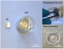 | ||
| Fig. 1 Preparation of LM-Al by ultrasonic treatment through cavitation induced by metallic jets surface erosion on Al surfaces. | ||
Results and discussion
Fig. 2(a) shows the color changes that occur in an ultrasonically prepared LM-Al with a 0.0097 wt% Al droplet when exposed to air. It is evident that the spontaneous coloration process of the LM-Al droplet occurs very rapidly, and the droplet changes from silver-white to dark brown in a manner similar to the passive coloration caused by electric oxidation in the solution.6 The fast discoloration of the LM due to the addition of Al creates a solid “skin” on the LM surface. As illustrated in Fig. 2(b), this solid “skin” can be peeled off through the cold rolling process. When the liquid core of the LM-Al droplet is extruded along the extrusion direction, the extrusion end of the solid “skin” breaks down and the solid “skin” is then peeled off, leaving a colored solid strip on the substrate. As a result of the reaction dependence of the LM-Al droplet, when the liquid core is extruded out, the surface reaction stops immediately, and the strip retains the color of the LM from the period before the extrusion. Additionally, the extruded LM-Al droplet will continue to react rapidly with the air and regenerate the solid “skin” on its surface. Clearly, the surface color of the strip can be adjusted by controlling the extrusion rate of the LM-Al droplet.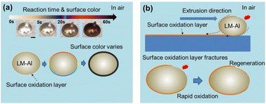 | ||
| Fig. 2 (a) Surface oxidation reaction-dependent coloration of LM-Al. (b) Schematic illustration of the extrusion rate-controlled real-time coloration of LM strips. | ||
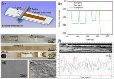
A schematic image of the rolling device used in this study is presented in Fig. 3(a). By using specific extrusion rates and applying specific pressures to the roller, a series of colorless/colored strips can be obtained, as shown in Fig. 3(b) and (c). After multiple attempts, it was found that when the extrusion rate reached approximately 0.7 mm s−1, the color of the strip (sample I) obtained was silver-white. A thin, flat layer similar to that obtained from Ga spontaneous oxidation could be observed on the strip via SEM, as shown in Fig. 3(d). When the extrusion rate was reduced to 0.3 mm s−1, a brown strip (sample II) was obtained. Using real-time extrusion rate control, a “zebra” colored strip (sample III) with silver-white, brown, and black stripes could be obtained easily. Microscopic morphologies show that these colorful strips have higher fluctuations and more layers when compared with the colorless layer, as shown in Fig. 3(e). Additionally, a cross-sectional view of the colored/colorless strips is presented in Fig. 3(f). The images show that the thicknesses of the colorless/colored strips that are peeled off by rolling are approximately 300–400 μm in thickness, with high roughness. The line scan results acquired by EDS indicate that metal oxidation mainly occurs in the colored strips, as shown in Fig. 3(f) and S1(b) and (d).† Additionally, a large amount of unoxidized LM is still present inside the colorless strips, as shown in Fig. S1(a) and (c).† Higher oxygen content was generally found on the surfaces of the colored/colorless strips, which means that more thorough oxidation occurs on these surfaces. Although the aluminum content in the LM is extremely low, there is still significant enrichment within the strips. Therefore, the aluminum dissolved within the LM diffuses rapidly and spontaneously to its surface and then undergoes oxidation, which results in the surface color changes on the LM.
The XPS results show that the surfaces of the colored strips obtained by controlling the extrusion rates of the LM-Al mainly consist of metal oxide composites, including Ga2O3, Ga2O, Al2O3, SnO2, SnO, In2O3, and In2O, as shown in Fig. 4(a)–(d). The presence of these metal oxide composites was also confirmed by the XRD results, as presented in Fig. S2.† It was also found that a considerable proportion of the LM-Al in the strips was not oxidized. From the microscopic structures of the strips, as presented in Fig. S3,† it can be inferred that the unoxidized metal may mainly originate from the core of the LM because of the rupturing of the surface oxide film caused by compression and the promotion of LM upwelling along the cracks. The XPS results also indicate that oxidation on the surface of the LM dominates the color change on its surface.13 Therefore, by controlling the degree of oxidation on the LM surface through extrusion, effective strip color control can be achieved. Note that the oxidation-induced color changes on the LM occurred within 60 s. As a result, the actual oxidation discoloration process on the LM surface is likely to be very intense and highly complex.
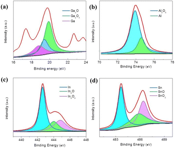 | ||
| Fig. 4 (a)–(d) Valence states of the elements present in the surface oxidation discoloration layer of the dark brown colored LM-Al acquired by XPS. | ||
Fig. 5 shows the temperature-rise curve and the infrared thermograph of the LM-Al during its discoloration process when exposed to air. The temperature of the entire LM rises rapidly from room temperature to 54 °C within a few tens of seconds and then slowly cools afterwards. As a result of the significant volume difference between the oxidized surface and the entire LM, the transient temperature rise in the LM surface may reach several hundred degrees Celsius, thus confirming that the highly intense oxidation reaction is localized on the surface of the LM. Consideration of the highly complex metal oxide composites and the gallium nitride that are rapidly formed on the surface of the LM indicates that the LM surface reaction could potentially be applied to the synthesis of challenging materials.
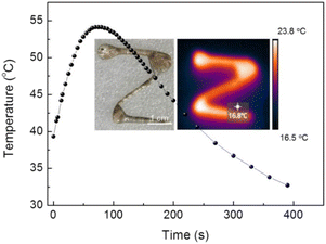 | ||
| Fig. 5 Temperature-rise curve of LM-Al during the discoloration process in air, with an inset infrared thermograph of the character “Z”. | ||
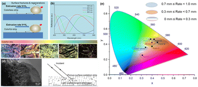
Fig. 6(a) clearly illustrates the relationship between the extrusion rate and the strip color. When the extrusion speed is sufficiently high (0.7 mm s−1), the oxide layers obtained on the colorless strips should be very thin. As reported in the literature,14 because of the spontaneous diffusion of Al to the surface of the LM, the main oxide component on the surface was initially alumina. As a result, alumina films have been used to reveal the optical properties of the color changes in the strips. Alumina films with thicknesses of 100 to 300 nm were used to calculate the reflectivity. The bottom of the Al2O3 film is simplified and treated as a mirror reflection layer. In addition, plane light with a wavelength range from 400 to 800 nm was used to illuminate the Al2O3 films vertically. According to the calculation results, when the alumina film thickness is less than 100 nm, the film appears to be almost fully transparent within the visible spectrum, as shown in Fig. 6(b). At this point, the color of the strip that was stripped by the extrusion process mainly comes from the color of the residual LM inside it, which is silver-white. If the extrusion rate that corresponds to the generation rate of a very thin and completely colorless oxide layer on the LM-Al is defined as V0, various colors can theoretically be obtained by reducing the extrusion rate such that V < V0. The calculation results show that when the oxide film thickness is within the range from 200 to 300 nm, the film will exhibit blue, red, and yellow-green color changes in sequence because of the interference effect. These color changes have been observed in the strips that were extruded and peeled off at different extrusion rates, as shown in Fig. 6(c). Additionally, the CIE-L*a*b* values marked from points I to V on these strips are presented in Table S1.† As the extrusion rate is reduced further, the oxide film on the LM continues to grow, and the amount of oxygen that enters the bottom of the film decreases; this leads to incomplete oxidation and generation of sub-oxides such as gallium oxide, which have a strong absorption capacity for visible light and thus cause the strips to appear brown at this time.15,16 Additionally, when the film thickness reaches a certain level, large numbers of micro-nanoscale porous structures will be generated inside the film. From an optical perspective,6,17 these porous micro-nanoscale structures have a strong light trapping capability. Therefore, when the oxidation reaction ceases, the LM surface usually appears to be black, as shown in Fig. 6(d). Furthermore, a CIE chromaticity diagram has been provided in Fig. 6(e) to establish a correlation for extrusion rates with colors. However, because the blue, red, and yellow-green films have similar thicknesses, it is difficult to distinguish them through the extrusion/peeling process. To achieve uniform colors in the stripes, the most typical silver-white stripes and brown stripes were selected.
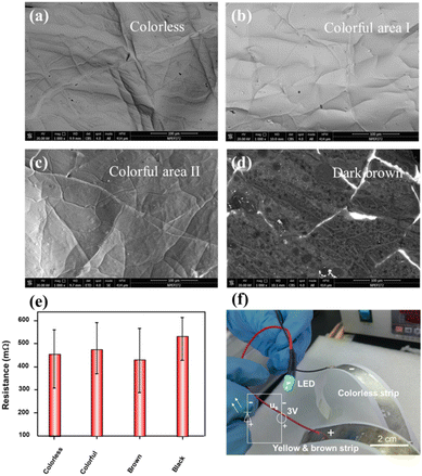
Although the surface of the color strip obtained via extrusion/peeling is oxidized, there is still a large amount of unoxidized LM in its center, and there are also multiple cracks on the surface oxide of the color strip; therefore, its conductivity can still be guaranteed by the unoxidized LM extrusion from these cracks, which forms a highly conductive network, as illustrated in Fig. 7(a)–(d) and S3 and S4.† As shown in Fig. 7(e), the resistances of all the strips are very low and range from 200.0 to 600.0 mΩ sq−1, regardless of their colors. As a result, the yellow-brown and silver-white colored strips were used and were bent to form flexible positive and negative electrodes, which enabled successfully lighting of a green light-emitting diode (LED) as shown in Fig. 7(f). It is evident that these differently colored strips can be used to differentiate effectively between the various conductive components contained in a flexible circuit.
Note that the lightly colored strips have fully oxidized surfaces when they present colors such as blue, red, and yellow-green based on the light interference. Under these conditions, because the reaction has already been completed quite thoroughly, color changes will not occur over time. For the dark colored strips, however, some of their color properties are dependent on absorption of light by the unstable protoxide, and thus some fading will occur over time. Furthermore, the colored strip prepared in this work is relatively fragile and is prone to scratching. Therefore, a protective film will be required to prevent fading and scratching of these colorful strips in future work.
Conclusions
In summary, we have presented a real-time color control method for fabrication of LM-based strips through cold rolling. By controlling the extrusion rate, LM strips with various colors can be obtained. XPS results indicate that the surface of the dark brown colored strip is mainly composed of metal oxide composite materials, including Ga2O3, Ga2O, Al2O3, SnO2, and In2O3, thus confirming that oxidation is the dominant factor in the surface color change. Furthermore, a highly intense oxidation reaction that is localized within the LM surface during the discoloration process is reported here. Through calculation and analysis of the oxide film thickness, it is observed that strips with thicknesses of less than 100 nm appear silver-white (corresponding to an extrusion rate of 0.7 mm s−1). When the film thickness ranges between 100 and 300 nm, the films appear with colors such as red, green, and blue. When the film thickness exceeds 300 nm (corresponding to an extrusion rate of less than 0.3 mm s−1), the surfaces of the strips appear to be brown or black as a result of the formation of large numbers of sub-oxides and porous trapping structures. This work shows great potential for use in fabrication of conductive flexible components with indicator functions in the flexible electronics field.Data availability
The data supporting this article have been included as part of the ESI.†Conflicts of interest
There are no conflicts to declare.Acknowledgements
This work was supported by Shandong Provincial Youth Innovation Science and Technology Project of Colleges and Universities (Grant No. 2021KJ089); Shandong Provincial Natural Science Foundation (Grant No. ZR2022ME197, ZR2023QF019); and Yantai Double Hundred Talent Plan 2019. We thank David MacDonald, MSc, from Liwen Bianji (Edanz) (https://www.liwenbianji.cn/) for editing the English text of a draft of this manuscript.Notes and references
- H. Chang, R. Guo, Z. Sun, H. Wang, Y. Hou, Q. Wang, W. Rao and J. Liu, Adv. Mater. Interfaces, 2018, 5, 1800571 CrossRef.
- L. Y. Zhou, J. Z. Fu, Q. Gao, P. Zhao and Y. He, Adv. Funct. Mater., 2020, 30, 1906683 CrossRef CAS.
- Z. Hou, H. Lu, Y. Li, L. Yang and Y. Gao, Front. Mater., 2021, 8, 647229 CrossRef.
- L. A. Akashev and V. I. Kononenko, Tech. Phys., 1998, 43, 853–854 CrossRef.
- S. Liang, W. Rao, K. Song and J. Liu, ACS Appl. Mater. Interfaces, 2018, 10, 1589–1596 CrossRef CAS.
- S. Liang and J. Liu, Sci. China: Technol. Sci., 2018, 61, 110–116 CrossRef.
- Y. Hou, H. Chang, K. Song, C. Lu, P. Zhang, Y. Wang, Q. Wang, W. Rao and J. Liu, ACS Appl. Mater. Interfaces, 2018, 10, 41627–41636 CrossRef CAS.
- L. Duan, Y. Zhang, J. Zhao, J. Zhang, Q. Li, Q. Lu, L. Fu, J. Liu and Q. Liu, Small, 2022, 18, 2204056 CrossRef CAS PubMed.
- A. Martin, W. Kiarie, B. Chang and M. Thuo, Angew. Chem., Int. Ed., 2020, 132, 360–365 CrossRef.
- Z. J. Farrell, A. R. Jacob, V. K. Truong, A. Elbourne, W. Kong, L. Hsiao, M. D. Dickey and C. Tabor, Chem. Mater., 2023, 35, 964–975 CrossRef CAS.
- S. Miyazaki, V. H. No, K. Kitamura, A. Khantachawana and H. Hosoda, Int. J. Plast., 2000, 16, 1135–1154 CrossRef CAS.
- L. Zhang, Z. H. Jin, L. H. Zhang, M. L. Sui and K. Lu, Phys. Rev. Lett., 2000, 85, 1484 CrossRef CAS.
- G. Moldovan, M. J. Roe, I. Harrison, M. Kappers, C. J. Humphreys and P. D. Brown, Philos. Mag., 2006, 86, 2315–2327 CrossRef CAS.
- A. Zavabeti, J. Z. Ou, B. J. Carey, N. Syed, R. Orrell-Trigg, E. L. Mayes, C. L. Xu, O. Kavehei, A. P. O’Mullane, R. B. Kaner, K. Kalantar-zadeh and T. Daeneke, Science, 2017, 358(6361), 332–335 CrossRef CAS PubMed.
- N. Horasawa, H. Nakajima, S. Takahashi and T. Okabe, Dent. Mater. J., 1997, 16, 200–208 CrossRef CAS.
- J. Zhao, H. Li, X. Bi and H. Dai, Mater. Chem. Phys., 2022, 291, 126726 CrossRef CAS.
- V. Grivickas and P. Basmaji, Thin Solid Films, 1993, 235, 234–238 CrossRef CAS.
Footnotes |
| † Electronic supplementary information (ESI) available. See DOI: https://doi.org/10.1039/d4ra03012e |
| ‡ Jing Liu and Hao Kang contributed equally to this work. |
| This journal is © The Royal Society of Chemistry 2024 |

