 Open Access Article
Creative Commons Attribution 3.0 Unported Licence
Lithium nitrate salt-assisted CO2 absorption for the formation of corrosion barrier layer on AZ91D magnesium alloy†
Gyoung G. Jang a,
Jiheon Jun
 *b,
Jong K. Keum
 c,
Yi-Feng Sub,
Mayur Poled,
Sridhar Nivertyd and
Vineet V. Joshid
aManufacturing Science Division, Oak Ridge National Laboratory (ORNL), Oak Ridge, TN 37831, USA. E-mail: jangg@ornl.gov
bMaterials Science and Technology Division, ORNL, USA. E-mail: junj@ornl.gov; suy1@ornl.gov
cCenter for Nanophase Materials Science and Neutron Scattering Division, ORNL, USA. E-mail: keumjk@ornl.gov
dEnergy and Environment Directorate, Pacific Northwest National Laboratory (PNNL), Richland, WA 99354, USA. E-mail: mayur.pole@pnnl.gov; sridhar.niverty@pnnl.gov; vineet.joshi@pnnl.gov
First published on 3rd June 2024
Abstract
Mg alloy corrosion susceptibility is a major issue that limits its wide industrial application in transport, energy and medical sectors. A corrosion-resistant layer containing crystalline MgCO3 was formed on the surface of AZ91D Mg alloy by Li salt loading and thermal CO2 treatment. Compared to the uncoated AZ91D surface, the surface layer exhibited up to a ∼15-fold increase in corrosion resistance according to the electrochemical results in 3.5 wt% NaCl solution and ∼32% decrease in wear rate compared to untreated AZ91D. The improved corrosion resistance is attributed to the formation of a <10 μm thick dense layer containing Mg, O, C and Li with crystalline MgCO3 phases. The initial step was to form a porous MgO layer on the surface of AZ91D Mg alloy, followed by loading an alkali metal salt (i.e., LiNO3) onto the MgO surface. The porous MgO surface was then reconstructed into a dense insulation layer containing Mg carbonate through CO2 absorption facilitated by molten Li salt during thermal CO2 treatment at 350 °C. As a potential method to utilize excessive CO2 for beneficial outcomes, the formation of the carbonate-containing film introduced in this study opens a new pathway for protecting various existing Mg alloys for diverse industrial applications.
Introduction
Magnesium (Mg) alloys are among the lightest structural materials and have a strong potential for constructing lightweight engineered systems. The use of such lightweight materials would reduce energy consumption and carbon emission, particularly in high-volume transportation applications.1–3 The other emerging applications of Mg alloys are in bioengineering implants and battery and fuel cell electrodes.4–7 Despite the long history of Mg alloy development, the widespread use of Mg alloys has been restricted by several intrinsic chemical and mechanical limitations including corrosion susceptibility,1,8–12 poor formability,2,13 and low creep resistance.14 Recent development efforts for new Mg alloy compositions (e.g., rare earth alloying) enabled overcoming these physical and mechanical material drawbacks.15,16 However, in most cases, these alloying strategies for mechanical property enhancement, such as creep resistance and/or strength, did not improve or even decrease corrosion resistance.17 Conversely, alloying for corrosion resistance, such as Ca doping, did not show mechanical property enhancement.18,19 Still, corrosion of Mg alloys is the most critical issue that needs to be addressed.Protective surface coatings are still considered the most cost-effective way to improving the corrosion resistance of Mg alloys without compromising the beneficial mechanical properties obtained through alloying. Various coating approaches have been examined for Mg and Mg alloys, including superhydrophobic coatings,20–22 plasma electrolytic oxidation and anodization,23–26 inorganic chemical and fluoride coatings,27–30 cold spray coatings31–34 or polymer coatings.35,36 However, a single coating alone is insufficient to provide adequate protection for Mg surfaces in automotive body applications. As a result, multilayer coating schemes using wet chemical processes have been proposed to ensure reliable Mg protection.1,37 It is important to consider the standard regulation set by the US Environmental Protection Agency since these wet-chemical-based coatings can generate volatile organic compounds. These conditions cause complexities in the processes, increase costs, and may result in insufficient corrosion protection.
Magnesium carbonate has the potential to serve as a corrosion barrier material. It is a stable compound with a very low solubility of 14 mg per 100 mL in water. This compound can remain inert in water for extended periods and thermodynamically favor the growth of a layer on the MgO surface in air.38,39 Although the formation of MgCO3 on the MgO surface (MgO(s) + CO2(g) ↔ MgCO3(s), ΔG = −21.4 kJ mol−1) is a spontaneous and thermodynamically favorable reaction,40,41 the growth of the carbonate layer is limited to the surface due to slow reaction kinetics. As a result, only a few nanometer-thick layers were formed as reported previously.42 Such thin layers cannot provide sufficient corrosion protection for bulk samples. To accelerate the growth of the MgCO3 film, Wang and others40 utilized excited CO2 to form a MgCO3 layer on pure Mg nanorods under electron-beam irradiation, while Jang and others43 employed atmospheric CO2 plasma to create a ∼500 nm thick carbon-rich layer on pure Mg, resulting in improved corrosion resistance on a larger scale. However, the achievement of a protective layer with sufficient coverage on Mg alloys has not been demonstrated.41
Recently, MgO-based mesoporous structures have received significant attention for energy-efficient CO2 capture. These low-cost materials exhibit a high theoretical capture capacity (e.g., 1.09 g CO2 per 1 g MgO) and demonstrate a wide sorption temperature range (25–350 °C).44 However, the limited mass transfer in bulk solid sorbents, such as micro MgO sorbent particles, poses a key technical challenge for CO2 absorption, resulting in only 5–20% sorption capacity even at room temperature and even high temperature (e.g., 200 °C). To address this technical issue, alkali nitrate molten salts can be employed to coat the MgO surface. The molten salt coating significantly enhances the CO2 sorption capacity, reaching up to ∼87% at intermediate temperature, thereby enabling a high yield of MgCO3.45 The molten salts, such as NaNO3, NaNO2, LiNO3, and KNO3, act as reaction media, dissolving both CO2 and MgO, thereby facilitating the kinetics of the carbonate formation reaction.46,47
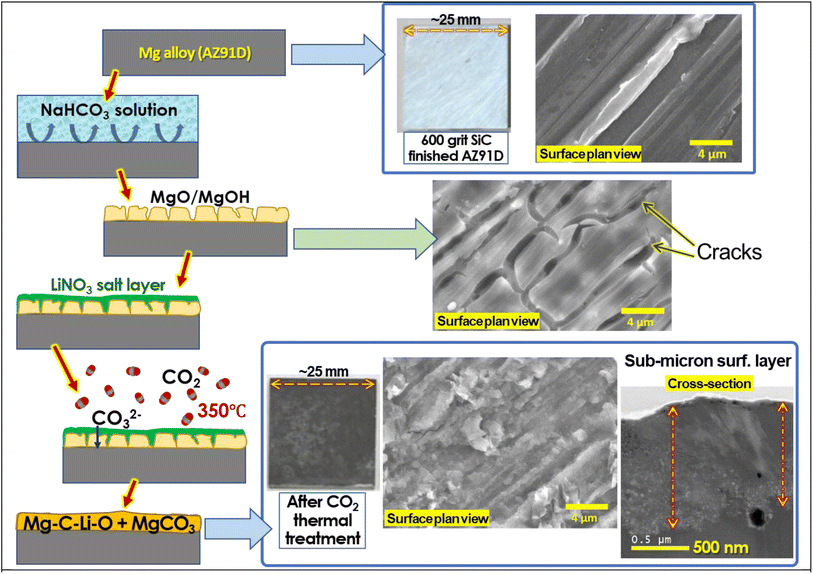
Inspired by the concept of molten salt coating on MgO particles for high-capacity CO2 absorption, we have explored a novel approach to form a dense and thick carbonate layer on the surface of Mg alloy metal, serving as an effective corrosion barrier. The approach involves enhancing the formation of a MgCO3 layer on a pre-formed MgO surface through thermal treatment of the salt-coated MgO surface in a CO2-rich environment, as schematically described in Fig. 1. Initially, the Mg alloy surface was treated with an aqueous salt solution, resulting in the formation of a porous and cracked MgO surface layer. Subsequently, an aqueous LiNO3 solution was coated on the pre-formed MgO surface and dried to form a solid salt layer. The CO2 thermal treatment, conducted at an intermediate temperature (300–350 °C), above the melting point of LiNO3 (253 °C), facilitated CO2 absorption through the molten salt layer, effectively converting the MgO layer to MgCO3.
 | ||
| Fig. 1 Schematic description of thermal CO2 treatment on Mg alloy specimens to form the corrosion barrier layer. The middle schematic is a graphical description of a key MgCO3 formation mechanism reported in ref. 48. | ||
The interaction of MgO with CO2 in molten LiNO3 supposedly occurs as follows (as described in Fig. 1):1 oxygen ion (O2−) and CO2 reaction forming CO32− in the molten salt layer and2 chemical reaction between CO32− and Mg2+ forming MgCO3. While the key mechanism of molten salt-assisted MgCO3 formation has been described in previous literature,45,46,49 those studies focused on zero-dimensional nano/microparticles for high-capacity CO2 absorption rather than large-scale 2D surfaces for corrosion mitigation. To the best of our knowledge, no study has proposed the utilization of this MgCO3 formation reaction to form a corrosion barrier coating for Mg alloys.
In this study, we conducted a proof-of-principle evaluation of the formation of a corrosion barrier layer with Mg–O–C–Li components. Various corrosion tests were performed, and advanced electron microscopic/X-ray-based chemical analyses were utilized to characterize the presence of carbon and Li. Additionally, real-time XRD analysis was employed to understand the formation mechanism. By simply using CO2 as the feeding gas, this approach has the potential to provide effective corrosion protection for various complex Mg alloy structures, including inner tube surfaces, 3D structures and other cast Mg structures. The tribological properties were also elucidated in this study to understand the role of the barrier layer formed by CO2 thermal treatment for improved surface wear properties. Moreover, the CO2 thermal treatment technique offers the advantage of minimizing environmental concerns associated with waste treatments often required by traditional wet-chemical-based methods for protective coatings on Mg alloys.
Experimental procedure
Materials
A commercial high-pressure die-cast AZ91D was obtained and analyzed for the chemical composition, which is summarized in Table 1. Test samples of AZ91D with the dimensions of 25 mm × 25 mm and thickness of ∼2 mm were prepared by electric discharge machining. The test samples were wet ground with silicon carbide (SiC) paper to a 600-grit finish, followed by ultrasonic cleaning in deionized water and drying with compressed air. Prior to CO2 thermal treatment, the samples were stored in a desiccator. All salt chemicals were purchased from Sigma-Aldrich, St. Louis, MO, USA.| Mg | Al | Zn | Mn | Minor elements: Cu, Fe & Ni |
|---|---|---|---|---|
| 89.95 | 9.24 | 0.59 | 0.22 | <0.001 |
Preparation of Li salt CO2-thermal-treated AZ91D samples
First, 600-grit SiC finished AZ91D coupons (25 × 25 mm2) were immersed in a 2.5 wt% aqueous NaHCO3 solution for 10 min to form a MgO layer on the surface. 10 or 25 wt% LiNO3 solution was prepared. An assigned amount of Li solution (0.1 mL) was drop-coated onto the pre-formed MgO surface, and the treated samples were dried in a convection oven at 60 °C. For example, a sample designated as 2.5–2.5 indicates that it was prepared by immersing the sample in a 2.5 wt% NaHCO3 solution for 10 min to form MgO, followed by loading it with 0.1 mL of a 25 wt% LiNO3 solution. Table 2 summarizes the sample nomenclatures and preparation conditions used for AZ91D.Thermal CO2 treatment was conducted using a 3-zone controlled alumina tube furnace (i.e., 1370 mm in length, 82 mm in diameter). The furnace temperature was raised to 350 °C over 3 h with argon purging gas. Once the target temperature was reached, lab-grade clean CO2 (99.995% purity) was supplied to the furnace at a flow rate of 300 mL min−1 for 3 h. After completing the treatment, both the furnace and CO2 supply were shut off, and argon purging was performed until the samples were cooled to 50 °C or below. The treated AZ91D samples were washed with deionized water under sonication for 5 min and then dried for further analysis. A graphic description of the entire treatment process can be found in Fig. 2.
Characterization of materials
Surface-treated AZ91D samples were analyzed by scanning electron microscopy (SEM) equipped with energy-dispersive X-ray spectroscopy (EDS), X-ray diffraction (XRD) and scanning transmission electron microscopy (STEM). The specimens for STEM analysis were prepared via the focus ion beam (FIB) milling technique by the in situ lift-out method using a Hitachi NB5000 dual-beam FIB-SEM. Prior to milling, protective layers of tungsten and carbon (4 mm wide, 20 mm long, and 0.5 mm thick) were deposited on the sample to preserve the area of interest during ion sputtering. Higher resolution microstructure image and elemental mapping in cross-section were carried out using a FEI model Talos F200X STEM operated at 200 kV, which is equipped with an extreme field emission gun (X-FEG) electron source and Super-X EDS (energy dispersive spectroscopy) system with 4 silicon drift detectors (SDD) and a JEOL JEM-2100F equipped with a Schottky field emission gun and Gatan image filter and spectrometer (GIF Quantum 963SE). In situ X-ray diffraction (XRD) measurements were conducted on a PANalytical X'Pert Pro MPD equipped with a TTK-450 X-ray reaction chamber (Anton-Paar) while purging CO2 gas into the chamber. For the XRD measurements, an X-ray beam was generated at 45 kV/40 mA, and the generated X-ray beam wavelength was λ = 1.5418 Å (CuKα radiation).Corrosion evaluation
The initial corrosion assessment was carried out using H2 gas evolution measurements during immersion in 3.5 wt% NaCl (aq) at ambient temperature (22–23.5 °C). Untreated and CO2-treated AZ91D samples with 25 × 25 mm2 in size were prepared for the measurement as described in the following sentences. All samples were masked with a polymer tape to expose 0.833 cm2 circular area (10.3 mm diameter) to NaCl solution. Each H2 evolution measurement had one treated or untreated Mg alloy sample that was positioned upright in a plastic container containing 3000 mL of 3.5 wt% NaCl (aq) open to air. During the experiments, deionized water was added to the NaCl solution every 48 or 72 h to compensate for water evaporation. An inverted funnel filled with 3.5 wt% NaCl (aq) was placed over the tape-masked sample to collect H2 evolved during corrosion over the immersion time. After exposure, the samples were removed from the solution, rinsed with deionized water and then ethanol, dried using compressed air, and photographed for collection of graphical data.Electrochemical impedance spectroscopy (EIS) and polarization measurements were also conducted for untreated (600 grit SiC finished) or treated AZ91D samples as working electrodes, with the exposed area of 0.833 cm2 (10.3 mm diameter) prepared by insulation tape masking. A reference saturated calomel electrode (SCE) and Pt plates with 3–5 cm2 of surface area for counter electrodes were used in 3.5 wt% NaCl solution open to air at ambient temperature. Before EIS or polarization measurement, an open-circuit potential (OCP) delay for 60 min was applied for the tape-masked AZ91D samples. EIS measurements after OCP delay were performed using the following parameters: ±10 mV amplitude with respect to the last corrosion potential (in OCP delay) and frequency range of 200 kHz to 7 mHz. For the impedance data fitting, Zview software version 4.0g (Scribner, Southern Pines, NC, USA) was used for two equivalent circuit models described later. For polarization measurements, the scanning was initiated at −2.25 VSCE and stepped up to −0.95 VSCE at a rate of 1 mV s−1.
Tribology test
Dry sliding reciprocating wear tests using a tabletop Anton Paar pin-on-disk tribometer were employed to characterize the friction and wear resistance of AZ91D specimens. Tests were performed in compliance with ASTM G-133 (ASTM G-133 2022). A 6 mm-diameter hard silicon nitride (Si3N4) is used as a counter face to mitigate the ball wear during sliding. Tests were conducted in ambient air under a normal load of 1 N at a sliding frequency of 5 Hz. Wear tests were run for a total sliding cycle of 5000 (at 5 Hz) with a 6 mm stroke length corresponding to 120 m of sliding distance to study the steady-state friction behavior. Tribo 1.4x software was used to record the coefficient of friction (COF) and the wear tracks were analyzed using a Keyence white light interferometry (WLI). 3D profile of the wear tracks was measured and analyzed to calculate the wear volume loss (mm3) using VR-5000 series software. Wear rates (units of mm3 N−1 m−1) were calculated by dividing wear volume loss by normal load and the sliding distance. At least three tests were carried out at room temperature and the average value was reported.Results and discussion
Initial characterization of CO2-treated Mg alloy surface
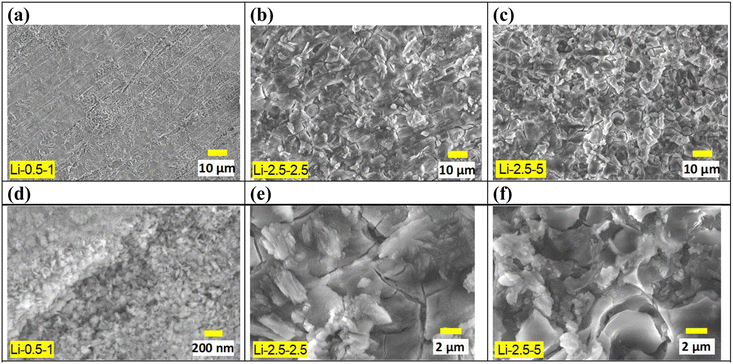
Significant changes in surface morphology were observed after CO2 treatment on the Li salt-coated MgO surfaces. Initially, a pre-treated AZ91D sample, prior to CO2 exposure, shows separated islands of MgO/Mg(OH)2 layers, as presented in Fig. 2. This morphology can be explained by a low Pilling–Bedworth ratio (PBR) of MgO and Mg, reported to be 0.81, indicating that the oxide layer was fractured on the Mg substrate and unable to effectively suppress further oxidation and the inward diffusion of oxygen, thus lacking protective effects.51 Note that the observed cracks and voids may appear more pronounced under an SEM observation environment characterized by vacuum and near-zero humidity. Fig. 3 shows that CO2 treatment of AZ91D with pre-loaded Li salt transformed the separated island structure of the pre-treated MgO/Mg(OH)2 (Fig. 2) into a more connected layer with embedded crystalline particles on the surface. The size of crystals on the CO2-treated surfaces was smaller in the Li-0.5-1 condition than the others. When MgO/MgOH2 formed AZ91D was CO2 treated without Li salt, the surface morphology characterized as the separated island structure was maintained, as presented in Fig. S1 in the ESI,† which indicates that molten Li salt during thermal CO2 treatment accounts for the morphology change of the surface layer on AZ91D.Carbonate layer formation
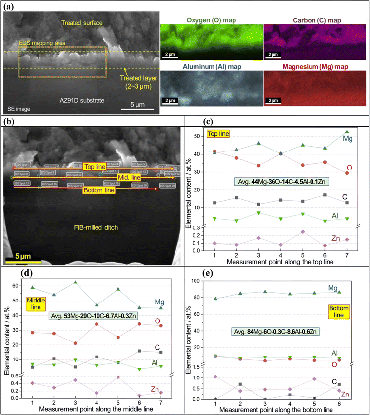
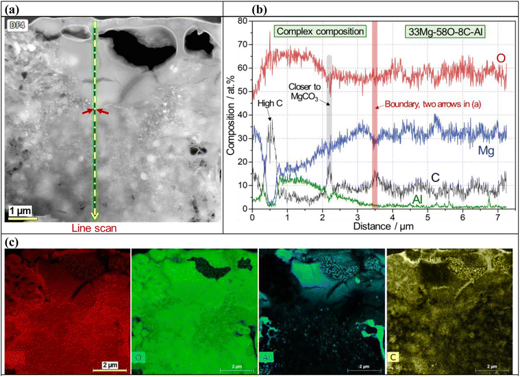
An SEM image and EDS maps of CO2-treated AZ91D specimen (Li-0.5-1 condition) are presented in Fig. 4a, which revealed 2–3 micron thick surface layer containing Mg, O and C with locally-enriched Al. In Fig. 4b, point EDS measurement spots in the cross-sectioned sample (prepared by FIB milling) are presented. Notably, the top and middle lines of the layer showed high carbon contents (average values of ∼14 and ∼10 at% for the top and middle sections, respectively), as presented in Fig. 4c and d, while the bottom layer near the AZ91D substrate showed only trace amounts of carbon (average of 0.3 at%), as found in Fig. 4e. XPS depth profiling on the same sample revealed similar results where the carbon content was 20 at% at the top surface and gradually decreased to ∼5 at% at a depth of 1.3 μm [see Fig. S3x-2 in the ESI†]. While the presence of Li in the surface layer is highly probable, detecting Li using generic SEM/STEM/EDS can be challenging due to the low energy X-ray associated with the low atomic number (Z = 3) of Li.52 Further analysis regarding Li detection will be discussed using EDS with a newly designed window-less detector.53The surface layer formed on the Li-2.5-2.5 AZ91D specimen was thicker than 7 μm, as confirmed by annular dark field (ADF) STEM with EDS characterization in Fig. 5 and S3 in the ESI.† A cross-sectional view of the layer, as shown in Fig. 5a, reveals at least 7 μm thick layer with void-like features on the upper region. EDS line scan of the CO2-treated layer in Fig. 5b exhibited complex composition profiles, including a high carbon spot, increased Al contents (3–14 at%) and probable MgCO3 phase in the top section but relatively flat Mg, O and C profiles (approximately 33Mg–58O–8C) in the lower section. In spatial EDS maps presented in Fig. 5c, Mg and O were uniformly distributed over the entire layer, while locally concentrated Al and C were also observed in the layer. As implied in the EDS line scan (Fig. 5b), C richer spots in the top portion of the layer (Fig. 5c) could be associated with the locations of MgCO3 crystalline phases.
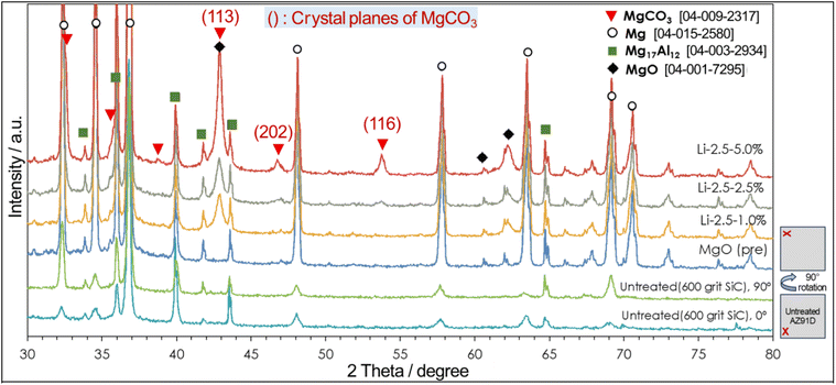
XRD measurements, as presented in Fig. 6, confirmed the presence of MgCO3 in the resultant surface layer. Compared to an untreated AZ91D (with 600 grit SiC finish) and MgO pre-formed AZ91D, thermal CO2-treated AZ91D samples showed three distinctive intensity peaks at 43.0°, 46.5°, and 54.0°, which can be assigned to the (113), (202), and (116) planes of the hexagonal MgCO3 phase. For a treated specimen with a low Li concentration of 1.0% (Li-2.5-1.0), only one predominant peak at 43.0° was observed. However, as the Li salt concentration increased to 5.0%, two additional peaks at 46.5° and 54.0° emerged, likely due to the increased amounts of MgCO3 crystals in thicker surface layers. For example, the Li-0.5-1.0 specimen formed ∼3 μm thick layer (see Fig. 4a), whereas the Li-2.5-5.0 specimen formed a layer thicker than 7 μm (see Fig. 5).
The different layer thicknesses between Li-0.5-1.0 and Li-2.5-5.0 samples should have resulted from the different loadings of both NaHCO3 and LiNO3. While the effect of NaHCO3 may influence the initial MgO growth, the detailed growth kinetics is difficult to assess due to lack of data. However, the effect of LiNO3 loading on the layer thickness growth can be assessed by a previous study, which reported that the amount of CO2 absorbed in LiNO3 increased as the loading of LiNO3 increased to 20 mol% on MgO.49 By increasing the amount of CO2 in the molten salt, the reaction to form MgCO3 can be enhanced, so the layer thickness can be increased.
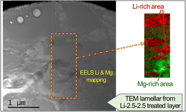
The layer also contained a lithium compound. Lithium nitrate salt was used to facilitate the formation of MgCO3, but it also may have simultaneously reacted with CO2 to form Li2CO3. However, evidence of crystalline Li2CO3 was not initially found in the XRD and XPS analyses, as the post-cleaning procedure (i.e., ultrasonication in deionized water for 5 min) must have washed off Li2CO3 on the top surface. Subsequent XRD and STEM characterization without washing the treated sample confirmed the presence of Li2CO3 crystals [Fig. S4 in the ESI†], which supports the formation of Li2CO3 from Li nitrate salt and CO2 reaction. To further characterize the presence of Li, an electron energy loss spectroscopy (EELS) survey in an ADF-STEM image was conducted, as presented in Fig. 7. The multiple linear least square fitting method was utilized to separate the overlapping Mg and Li edges at 51 eV and 55 eV, respectively, and Mg and Li richer areas in the surface layer are mapped using different colors. It is observed that Li richer area is associated with darker contrast in the ADF-STEM image.
Layer formation mechanism
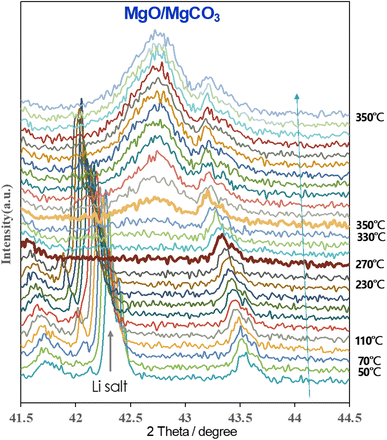
In situ XRD measurements were performed to understand the real-time formation of the carbonate layer through CO2 thermal treatment on Li salt-coated AZ91D, as shown in Fig. 8. During heating from room temperature to an intermediate temperature of 250 °C, a peak at 42.3° assigned to [113] of LiNO3 gradually shifted to smaller angles due to lattice expansion. The crystalline peak disappeared when the temperature reached 270 °C, corresponding to the melting point of LiNO3 at 255 °C. Subsequently, a new crystal peak at 42.7° associated with MgCO3 formation appeared at 330 °C, and the peak intensity (indicative of the volume fraction of crystals) increased over time. At 350 °C, the crystal growth reached a steady state after 90 min and showed no further change in XRD peaks until the end of CO2 treatment after 3 h. This real-time monitoring of XRD peak evolution provides insights into key reactions, such as Li salt melting, CO2 reactive absorption, and MgCO3 crystal-containing layer growth, as functions of temperature and time during the CO2 treatment.Corrosion mitigation evaluation by H2 collection measurement
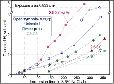
The reconstructed surface exhibited a notable increase in corrosion resistance, as evidenced by preliminary H2 collection results. A photo of the H2 collection measurement setup is presented in Fig. S5a in the ESI.† Fig. 9 presents that the collected H2 volumes from the CO2-treated samples (i.e., Li-2.5-2.5 and Li-2.5-5.0) were lower than those of the two untreated AZ91D samples for immersion times longer than 140 h in 3.5 wt% NaCl solution. An exception was that one untreated AZ91D showed low H2 volumes (downward triangle in Fig. 9). These notably different corrosion rates among the untreated AZ91D are presumably attributed to the local variations of cast microstructures. It was reported that the corrosion rates estimated by H2 collection data can vary up to a factor of 2.5 between the maximum and minimum data54 or ±44% deviation with respect to the average55 for AZ91D, as summarized in Table 3. It is also noted that AE42 and AM60 Mg alloys showed notable variations in H2 collection data. These previous results confirm that the relatively high variation of H2 volumes for the untreated AZ91D samples in Fig. 9 is a natural behavior.| Mg alloy | Corrosion exposure condition | Max. & min. H2 volume or converted data | Max./min. | Avg. H2 volume (A) | Standard deviation (B) | (B/A) × 100 | Reference |
|---|---|---|---|---|---|---|---|
| AZ91D | 5% NaCl for <100 h | ∼5.5 & ∼3.5 mg per cm2 per day | 1.57 | — | — | — | Song 2001 (ref. 56) |
| AZ91D | 0.1 M NaCl for 170 h | 4 & 1.6 mL | 2.5 | — | — | — | Brady 2019 (ref. 54) |
| AZ31B | 0.1 M NaCl for 170 h | 24.2 & 18.9 mL | 1.28 | — | — | — | Brady 2019 (ref. 54) |
| AE42 | 3.5% NaCl for 168 h | 1.2 & 0.77 mL cm−2 | 1.56 | — | — | — | Dargusch 2021 (ref. 57) |
| AZ91D | 0.6 M NaCl for 24 h | — | — | 0.45 mL | ±0.2 mL | ±44% | Bland 2022 (ref. 55) |
| AM60 | 0.6 M NaCl for 24 h | — | — | 0.3 mL | ±0.3 mL | ±100% | Bland 2022 (ref. 55) |
In visual inspection after the corrosion exposure, a CO2-treated AZ91D sample surface showed much smaller areas of corrosion attack compared to the untreated AZ91D [Fig. S5b and S5c in the ESI†]. The results of H2 collection are consistent with the electrochemical data discussed later in Fig. 10 and 11. In order to understand the effect of annealing without CO2 on the Li salt loaded sample (Li-2.5-2.5), thermal argon (Ar) treated samples (2.5-2.5 w/Ar) were prepared using the same process conditions. The Ar-annealed sample (filled square symbols in Fig. 9) exhibited higher H2 volumes than the untreated samples after 100 h, implying no corrosion mitigation effect.
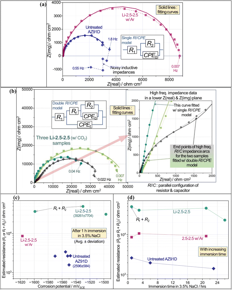 | ||
| Fig. 10 Electrochemical corrosion evaluation results for untreated (600 grit SiC finish) and Li-2.5-2.5 treated (with CO2 or Ar) AZ91D samples in 3.5 wt% NaCl solution. (a and b) Typical Nyquist impedance plots of untreated and treated AZ91D specimens with equivalent circuits as insets and data fitting curves. In (b), another inset on the right shows the impedance data in a lower impedance plane. R2 or Rf + R2 values (c) versus corrosion potential after 1 h immersion, and (d) with increasing immersion time. The detailed fitting results of impedance data are summarized in Tables S1–S3 in ESI.† The chi-square values of all fittings, reported in Tables S1–S3,† were lower than 0.002, which was used as a quality control for data fitting results. | ||
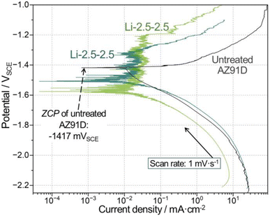 | ||
| Fig. 11 Comparison of polarization curves between one untreated and two individual Li-2.5-2.5 treated samples. | ||
Electrochemical corrosion evaluation
CO2-treated AZ91D surface significantly increased corrosion reaction resistance, as revealed by comparison of impedance scales in Fig. 10a and b for both treated and untreated specimens in 3.5 wt% NaCl solutions for 1 h immersion. The scale (or size) of impedance was greater for the Li-2.5-2.5 CO2-treated specimen. It is also noted that two Li-2.5-2.5 treated AZ91D samples exhibit smaller impedance arcs, associated with R//C (parallel configuration of resistor and capacitor) behavior at high-frequency regime, before the larger major impedance arcs as seen in the right inset of Fig. 10b. To account for the different shapes of impedance spectra, two equivalent circuit models depicted in Fig. 10a and b were used for impedance data fitting, which would also enable quantitative evaluation of corrosion resistance in each untreated or treated AZ91D sample.In the single R//CPE model (CPE: constant phase element) with R2 and CPE0, R2 is the charge transfer resistance of anodically dissolving metal(s) at the corroding interface, while CPE0 represents non-ideal capacitive behavior associated with the anodic metal dissolution. In the double R//CPE model with Rf, R2, CPE0 and CPEf, Rf and CPEf correspond to the resistance and non-ideal capacitance of permeable solid film, while R2 and CPE0 are the elements as described for the single R//CPE model. For both models, R1 is the solution resistance. The corrosion resistance of each sample was evaluated using R2 and Rf + R2 for the single and double R//CPE models, respectively, as reported previously.50,58 Note that there were other literature studies that took low-frequency inductive behavior into consideration for the corrosion evaluation of Mg and Mg alloys.26,55,59,60 However, a simpler impedance data fitting using the single R//CPE model without an inductive element is adopted here for untreated AZ91D, where inductive impedance was evident between 1.8 and 0.55 Hz (see Fig. 10a).
Fig. 10c indicates that an optimized CO2-treated sample (i.e., Li-2.5-2.5) exhibits approximately 15 times greater corrosion resistance than the untreated surface (avg. resistances: 39![[thin space (1/6-em)]](https://www.rsc.org/images/entities/char_2009.gif) 261 vs. 2596 ohm cm−2). This high corrosion resistance persisted for up to 26 h, as presented in Fig. 10d. Additionally, it appears that the inert Ar treatment results in an effective increase in impedance for a relatively short time immersion (see a square symbol in Fig. 10c and d), even though the formed layer was peeled off after washing and did not show corrosion protection in long-term H2 collection results (see Fig. 9).
261 vs. 2596 ohm cm−2). This high corrosion resistance persisted for up to 26 h, as presented in Fig. 10d. Additionally, it appears that the inert Ar treatment results in an effective increase in impedance for a relatively short time immersion (see a square symbol in Fig. 10c and d), even though the formed layer was peeled off after washing and did not show corrosion protection in long-term H2 collection results (see Fig. 9).
Polarization measurements in Fig. 11 showed that CO2-treated AZ91D surfaces exhibited passivity-like behavior (between −1.55 and −1.2 VSCE), where Mg anodic dissolution was much smaller than the untreated AZ91D. While different zero current potential (ZCP) values were noted for the treated and untreated AZ91D samples, as seen in Fig. 11, no further discussion was made because ZCP values could fluctuate during dynamics polarization measurements and significantly differ from corrosion potentials. For example, the ZCP of untreated AZ91D (−1417 mVSCE, as indicated in Fig. 11) is notably more noble than the corrosion potential values (<−1540 mVSCE as seen in Fig. 10c) during OCP measurements.
Considering the long-term H2 collection and electrochemical evaluation data, it is reasonable to state that CO2-treated AZ91D surfaces are distinctively more corrosion-resistant. The protection of Mg–C–O–Li and MgCO3 containing surface layer for AZ91D substrate is presumably attributed to a physical barrier effect limiting the permeation of corrosive species. Chemically induced corrosion mitigation, from the evolution of corrosion inhibitor(s) during the exposure, is open for further investigation.
Wear property of the layer
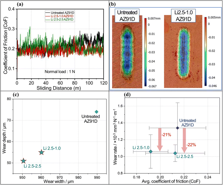
CO2-treated surface layers exhibited higher wear resistance, resulting in a lower wear rate. Typical coefficient of friction (CoF) curves as a function of sliding distance for untreated and CO2-treated AZ91D samples are plotted in Fig. 12a. The steady-state friction coefficients were obtained by dividing the mean friction force recorded during each experiment (after running-in) by the applied normal force. It is observed that all samples exhibited steady-state CoF in less than 3 meters (run-in period) of the total sliding distance, and there is no significant indication of fluctuations in the CoF over the entire sliding distance. The steady-state friction (μss = 0.21 ± 0.02) amplitude for all the above conditions, despite the factor of a barrier layer, can be attributed to less plastic deformation of the worn surface and relatively low adhesion of the contact surfaces sliding at 1 N of normal load.Fig. 12b illustrates comparative 3D wear surface maps of untreated and Li-2.5-1.0 AZ91D specimens as examples of raw wear data. The micro grooving, parallel to the sliding direction, visible on the wear tracks can be indicative of abrasive wear as the dominant wear mechanism. The depth and width of wear tracks for each AZ91D sample are plotted in Fig. 12c. It is evident that the wear dimensions of CO2-treated AZ91D samples, Li-2.5-2.5 and Li-2.5-1.0, were smaller than the untreated AZ91D specimen. This can be attributed to the resistance to plastic deformation when compared to that of the untreated sample. The average CoF and wear rate with the standard deviations are plotted in Fig. 12d. All CO2-treated AZ91D sample data indicate greater wear resistance compared to the untreated AZ91D. The average CoF was lower in the Li-2.5-1.0 sample (∼10% reduction) than the Li-2.5-2.5 and untreated AZ91D samples (as seen on the x-axis of Fig. 12d).
Interestingly, among the CO2 treated specimens, Li-2.5-2.5 AZ91D shows the lowest wear rate (1.04 × 10⁻³ mm3 N−1 m−1), which is ∼22% lower than that of the untreated AZ91D (1.34 × 10⁻³ mm3 N−1 m−1). The higher wear rate of untreated AZ91D can be attributed to the initial formation of discontinuous MgO upon sliding and then later dislodging of the oxides, causing severe abrasive wear on the exposed Mg metal. In contrast, the MgCO3 contatning barrier layer present on Li-2.5-2.5 AZ91 showed the lowest wear rate, which can be due to the partial smearing of the barrier layer in the matrix and increasing the shear strength of the substrate.61
Conclusion
In this work, we have demonstrated that Li-salt-assisted thermal CO2 treatment on AZ91D resulted in the formation of a highly corrosion-resistant surface layer through CO2 absorption into the MgO layer with molten Li salt. High-resolution microscopic/chemical analysis and in situ XRD measurements were conducted to quantify the chemical composition of the barrier surface layer and elucidate the surface layer characteristics, including the presence of MgCO3 crystalline phase and uniform distribution of Mg, C and O, and the temperature (330 °C) associated with MgCO3 phase formation under molten Li salt and CO2 environment.The corrosion protection and wear resistance performance were evaluated through electrochemical measurement, hydrogen collection and tribological characterization on various specimens. The CO2-treated AZ91D exhibited a 15-fold increase in long-term corrosion resistance (as assessed using impedance data) in 3.5 wt% NaCl and 21–22% lower wear rate (as revealed using wear volume data) compared to the untreated AZ91D specimen. Characterization results from SEM/STEM/EDS, STEM-EELS and XRD indicated that the unprotective MgO layer with separated island structure was completely transformed into a more compact and protective Mg–O–C–Li layer with MgCO3 crystalline phases.
The formation of a protective surface film, as demonstrated in this work, holds promise for environmentally friendly corrosion protection and excessive CO2 utilization. It opens new possibilities for protecting various existing Mg-based alloys for diverse applications. However, further optimization of the Li-salt-assisted CO2 thermal process is required for its application in complex Mg alloy structures. Each operational condition should be explored for various Mg alloy types with different thermal–mechanical properties and chemical reactivity to ensure effective protection.
Conflicts of interest
There are no conflicts to declare.Acknowledgements
This work was supported by the US Department of Energy's (DOE's) Office of Energy Efficiency and Renewable Energy, Vehicle Technology Office, Lightweight Materials Core Program. Part of the materials characterization (SEM and in situ XRD) was performed at the Center for Nanophase Materials Sciences, which is sponsored at ORNL by DOE's Scientific User Facilities Division. This manuscript has been authored by UT-Battelle, LLC, under contract DE-AC05-00OR22725 with the US Department of Energy (DOE). The US government and the publisher, by accepting the article for publication, acknowledge that the US government retains a nonexclusive, paid-up, irrevocable, worldwide license to publish or reproduce the published form of this manuscript or allow others to do so for US government purposes. DOE will provide public access to these results of federally sponsored research in accordance with the DOE Public Access Plan (http://energy.gov/downloads/doe-public-access-plan).References
- M. P. Brady, W. J. Joost and C. D. Warren, Insights from a Recent Meeting: Current Status and Future Directions in Magnesium Corrosion Research, Corrosion-US, 2017, 73, 452–462 CrossRef CAS PubMed.
- W. J. Joost and P. E. Krajewski, Towards magnesium alloys for high-volume automotive applications, Scr. Mater., 2017, 128, 107–112 CrossRef CAS.
- J. H. Jun, et al., Galvanic corrosion of AZ31B joined to dual-phase steel with and without Zn layer by ultrasonic and friction stir welding, J. Magnesium Alloys, 2023, 11, 462–479 CrossRef CAS.
- N. Shrestha, K. S. Raja and V. Utgikar, Mg-RE Alloy Anode Materials for Mg-Air Battery Application, J. Electrochem. Soc., 2019, 166, A3139–A3153 CrossRef.
- U. Riaz, I. Shabib and W. Haider, The current trends of Mg alloys in biomedical applications-A review, J. Biomed. Mater. Res., Part B, 2019, 107, 1970–1996 CrossRef CAS PubMed.
- N. S. Hazri, S. Basri, S. K. Kamarudin and A. M. Zainoodin, Critical review on development of magnesium alloy as anode in Mg-Air fuel cell and additives in electrolyte, Int. J. Energy Res., 2021, 45, 15739–15759 CrossRef CAS.
- J. Xu, et al., The effects of NaF concentration on electrochemical and corrosion behavior of AZ31B magnesium alloy in a composite electrolyte, RSC Adv., 2017, 7, 5880–5887 RSC.
- S. Bender, J. Goellner, A. Heyn and E. Boese, Corrosion and corrosion testing of magnesium alloys, Mater. Corros., 2007, 58, 977–982 CrossRef CAS.
- M. Liu, Y. Guo, J. Wang and M. Yergin, Corrosion avoidance in lightweight materials for automotive applications, npj Mater. Degrad., 2018, 2, 24 CrossRef.
- W. Q. Xu, et al., A high-specific-strength and corrosion-resistant magnesium alloy, Nat. Mater., 2015, 14, 1229–1235 CrossRef CAS PubMed.
- J. Jun, Y. C. Lim, Y. Li, C. D. Warren and Z. L. Feng, Mitigation of Galvanic Corrosion in Bolted Joint of AZ31B and Carbon Fiber-Reinforced Composite Using Polymer Insulation, Materials, 2021, 14(7), 1670 CrossRef CAS PubMed.
- Q. Zhang, Q. Li and X. Chen, Effect of heat treatment on corrosion behavior of Mg–5Gd–3Y–0.5Zr alloy, RSC Adv., 2020, 10, 43371–43382 RSC.
- D. Griffiths, Explaining texture weakening and improved formability in magnesium rare earth alloys, Mater. Sci. Technol., 2015, 31, 10–24 CrossRef CAS.
- M. S. Dargusch, S. M. Zhu, J. F. Nie and G. L. Dunlop, Microstructural analysis of the improved creep resistance of a die-cast magnesium-aluminium-rare earth alloy by strontium additions, Scr. Mater., 2009, 60, 116–119 CrossRef CAS.
- N. Mo, et al., Current development of creep-resistant magnesium cast alloys: A review, Mater. Des., 2018, 155, 422–442 CrossRef CAS.
- Y. C. Zhang, et al., Effect of Ca and Sr on the compressive creep behavior of Mg–4Al–RE based magnesium alloys, Mater. Des., 2014, 63, 439–445 CrossRef CAS.
- N. Birbilis, M. A. Easton, A. D. Sudholz, S. M. Zhu and M. A. Gibson, On the corrosion of binary magnesium-rare earth alloys, Corros. Sci., 2009, 51, 683–689 CrossRef CAS.
- Q. Pang, M. Song, R. Kalsar, V. V. Joshi and P. V. Sushko, Water Adsorption and Surface Atom Detachment on Zn, Al, Ce-Doped Mg Surfaces, Miner., Met. Mater. Soc., 2022, 291–292 Search PubMed.
- M. Deng, et al., Approaching “stainless magnesium” by Ca micro-alloying, Mater. Horiz., 2021, 8, 589–596 RSC.
- G. G. Jang, et al., The anti-soiling performance of highly reflective superhydrophobic nanoparticle-textured mirrors, Nanoscale, 2018, 10, 14600–14612 RSC.
- G. G. Jang, et al., Transparent superhydrophilic and superhydrophobic nanoparticle textured coatings: comparative study of anti-soiling performance, Nanoscale Adv., 2019, 1, 1249–1260 RSC.
- J. Yuan, J. Wang, K. Zhang and W. Hu, Fabrication and properties of a superhydrophobic film on an electroless plated magnesium alloy, RSC Adv., 2017, 7, 28909–28917 RSC.
- A. F. Cipriano, et al., Anodization of magnesium for biomedical applications – Processing, characterization, degradation and cytocompatibility, Acta Biomater., 2017, 62, 397–417 CrossRef CAS PubMed.
- H. Asoh, K. Asakura and H. Hashimoto, Effect of alcohol addition on the structure and corrosion resistance of plasma electrolytic oxidation films formed on AZ31B magnesium alloy, RSC Adv., 2020, 10, 9026–9036 RSC.
- Y. Chen, et al., Improving the corrosion resistance of micro-arc oxidation coated Mg–Zn–Ca alloy, RSC Adv., 2020, 10, 8244–8254 RSC.
- Y. Zhang, B. Liao, L. Xu, S. Wan and X. Guo, A novel anti-corrosion and antibacterial integrated MAO/PCNZ composite coating on AZ31B Mg alloy, Surf. Coat. Technol., 2024, 483, 130794 CrossRef CAS.
- J. Dzikova, et al., Characterization and Corrosion Properties of Fluoride Conversion Coating Prepared on AZ31 Magnesium Alloy, Coatings, 2021, 11(6), 675 CrossRef CAS.
- A. Nikbakht, C. Dehghanian and R. Parichehr, Silane coatings modified with hydroxyapatite nanoparticles to enhance the biocompatibility and corrosion resistance of a magnesium alloy, RSC Adv., 2021, 11, 26127–26144 RSC.
- Z. Ding, et al., Anticorrosion behaviour and tribological properties of AZ31 magnesium alloy coated with Nb2O5/Nb2O5–Mg/Mg layer by magnetron sputtering, RSC Adv., 2022, 12, 28196–28206 RSC.
- J. Yuan, B. Dai, X. Cui and P. Li, The effects of electrodeposition temperature on morphology and corrosion resistance of calcium phosphorus coatings on magnesium alloy: comparative experimental and molecular dynamics simulation studies, RSC Adv., 2023, 13, 34145–34156 RSC.
- H. L. Yao, et al., Microstructure and Corrosion Behavior of Thermal-Sprayed Hydroxyapatite/Magnesium Composite Coating on the Surface of AZ91D Magnesium Alloy, J. Therm. Spray Technol., 2019, 28, 495–503 CrossRef CAS.
- F. F. Lu, et al., Enhanced corrosion resistance of cold-sprayed and shot-peened aluminum coatings on LA43M magnesium alloy, Surf. Coat. Technol., 2020, 394, 125865 CrossRef CAS.
- S. Niverty et al., in Magnesium Technology 2023, ed. S. Barela, A. Leonard, P. Maier, N. R. Neelameggham and V. M. Miller, Springer Nature Switzerland, Cham, 2023, pp. 49–51 Search PubMed.
- S. Niverty, et al., Probing corrosion using a simple and versatile in situ multimodal corrosion measurement system, Sci. Rep., 2023, 13, 16695 CrossRef CAS PubMed.
- W. Xu, K. Yagoshi, Y. Koga, M. Sasaki and T. Niidome, Optimized polymer coating for magnesium alloy-based bioresorbable scaffolds for long-lasting drug release and corrosion resistance, Colloids Surf., B, 2018, 163, 100–106 CrossRef CAS PubMed.
- G. G. Jang, et al., Corrosion Prevention of Additively Manufactured Aluminum Packing Devices Developed for Process Intensification of CO2 Capture by Aqueous Amines, Ind. Eng. Chem. Res., 2021, 60, 17036–17044 CrossRef CAS.
- N. K. Akafuah, et al., Evolution of the Automotive Body Coating Process-A Review, Coatings, 2016, 6(2), 24 CrossRef.
- K. Rausis, A. R. Stubbs, I. M. Power and C. Paulo, Rates of atmospheric CO2 capture using magnesium oxide powder, Int. J. Greenhouse Gas Control, 2022, 119, 103701 CrossRef CAS.
- N. McQueen, P. Kelemen, G. Dipple, P. Renforth and J. Wilcox, Ambient weathering of magnesium oxide for CO2 removal from air, Nat. Commun., 2020, 11, 3299 CrossRef CAS PubMed.
- Y. Wang, et al., Turning a native or corroded Mg alloy surface into an anti-corrosion coating in excited CO2, Nat. Commun., 2018, 9, 4058 CrossRef PubMed.
- G. G. Jang, et al., Atmospheric Pressure Plasma Treatment of Magnesium Alloy for Enhanced Coating Adhesion and Corrosion Resistance, Coatings, 2023, 13(5), 897 CrossRef CAS.
- C. Fotea, J. Callaway and M. R. Alexander, Characterisation of the surface chemistry of magnesium exposed to the ambient atmosphere, Surf. Interface Anal., 2006, 38, 1363–1371 CrossRef CAS.
- G. G. Jang, et al., Formation of carbon and oxygen rich surface layer on high purity magnesium by atmospheric carbon dioxide plasma, J. Magnesium Alloys, 2023, 11, 88–99 CrossRef CAS.
- Y. C. Hu, Y. F. Guo, J. Sun, H. L. Li and W. Q. Liu, Progress in MgO sorbents for cyclic CO2 capture: a comprehensive review, J. Mater. Chem. A, 2019, 7, 20103–20120 RSC.
- Y. Q. Qiao, et al., Alkali Nitrates Molten Salt Modified Commercial MgO for Intermediate-Temperature CO2 Capture: Optimization of the Li/Na/K Ratio, Ind. Eng. Chem. Res., 2017, 56, 1509–1517 CrossRef CAS.
- W. L. Gao, et al., Molten salts-modified MgO-based adsorbents for intermediate-temperature CO2 capture: A review, J. Energy Chem., 2017, 26, 830–838 CrossRef.
- W. L. Gao, T. T. Zhou, Y. S. Gao, Q. Wang and W. R. Lint, Study on MNO3/NO2 (M = Li, Na, and K)/MgO Composites for Intermediate-Temperature CO2 Capture, Energy Fuels, 2019, 33, 1704–1712 CrossRef CAS.
- T. Harada, F. Simeon, E. Z. Hamad and T. A. Hatton, Alkali Metal Nitrate-Promoted High-Capacity MgO Adsorbents for Regenerable CO2 Capture at Moderate Temperatures, Chem. Mater., 2015, 27, 1943–1949 CrossRef CAS.
- W. L. Gao, et al., Molten Salt-Promoted MgO Adsorbents for CO2 Capture: Transient Kinetic Studies, Environ. Sci. Technol., 2021, 55, 4513–4521 CrossRef CAS PubMed.
- J. Jun, et al., Open-air plasma-assisted deposition of organosilicon coating for corrosion protection of AZ91D Mg alloy, J. Coat. Technol. Res., 2024, 21, 1097–1111 CrossRef CAS.
- F. Czerwinski, Oxidation Characteristics of Magnesium Alloys, Jom-US, 2012, 64, 1477–1483 CrossRef CAS.
- V. Thiery and H. B. Farhat, Lithium-bearing minerals under the scanning electron microscope equipped with energy dispersive spectrometry: Challenges, recent advances and prospects, Chem. Geol., 2023, 633, 121573 CrossRef CAS.
- P. Hovington, et al., Can we detect Li K X-ray in lithium compounds using energy dispersive spectroscopy?, Scanning, 2016, 38, 571–578 CrossRef CAS PubMed.
- M. P. Brady, et al., Magnesium Alloy Effects on Plasma Electrolytic Oxidation Electro-Ceramic and Electro-Coat Formation and Corrosion Resistance, J. Electrochem. Soc., 2019, 166, C492–C508 CrossRef CAS.
- L. G. Bland, L. C. Scully and J. R. Scully, Assessing the Corrosion of Multi-Phase Mg-Al Alloys with High Al Content by Electrochemical Impedance, Mass Loss, Hydrogen Collection, and Inductively Coupled Plasma Optical Emission Spectrometry Solution Analysis, Corrosion, 2017, 73, 526–543 CrossRef CAS PubMed.
- G. L. Song, A. Atrens and D. StJohn, An hydrogen evolution method for the estimation of the corrosion rate of magnesium alloys, Magnesium Technology 2001, 2001, pp. 255–262 Search PubMed.
- M. S. Dargusch, Z. M. Shi, H. L. Zhu, A. Atrens and G. L. Song, Microstructure modification and corrosion resistance enhancement of die-cast Mg-Al-Re alloy by Sr alloying, J. Magnesium Alloys, 2021, 9, 950–963 CrossRef CAS.
- Y. M. Jin, et al., Microstructure-corrosion behaviour relationship of micro-alloyed Mg-0.5Zn alloy with the addition of Ca, Sr, Ag, In and Cu, Mater. Des., 2020, 195, 108980 CrossRef CAS.
- A. D. King, N. Birbilis and J. R. Scully, Accurate Electrochemical Measurement of Magnesium Corrosion Rates; a Combined Impedance, Mass-Loss and Hydrogen Collection Study, Electrochim. Acta, 2014, 121, 394–406 CrossRef CAS.
- M. Curioni, F. Scenini, T. Monetta and F. Bellucci, Correlation between electrochemical impedance measurements and corrosion rate of magnesium investigated by real-time hydrogen measurement and optical imaging, Electrochim. Acta, 2015, 166, 372–384 CrossRef CAS.
- Y. Zhou, et al., Tribochemical Behavior of Pure Magnesium During Sliding Friction, Metals, 2019, 9(3), 311 CrossRef CAS.
Footnote |
| † Electronic supplementary information (ESI) available. See DOI: https://doi.org/10.1039/d4ra02829e |
| This journal is © The Royal Society of Chemistry 2024 |

