
 Open Access Article
 This Open Access Article is licensed under a Creative Commons Attribution-Non Commercial 3.0 Unported Licence
Core–shell particle formation via Co-assembly of AB diblock copolymers and nanoparticles in 3D soft confinement
Liangjun Ma,
Runyu Duan,
Ganghui Cao,
Hajinuer Bahetihan and
Weixin Kong *
*
Department of Physics, University of Xinjiang, Urumqi, CN, China. E-mail: kongwx@xju.edu.cn
First published on 15th July 2024
Abstract
Core–shell particle formation via co-assembly of AB diblock copolymers and nanoparticles in 3D soft confinement was studied using a simulated annealing method. Several sequences of soft confinement-induced core–shell particles were predicted as functions of the volume fraction of the nanoparticle to core–shell particles, the incompatibility between blocks, the volume fractions of A-blocks, the chain length of AB diblocks, the eccentricity of the nanoparticle, and the initial concentration of copolymers. Simulation results demonstrate that those factors are able to tune the morphology of the core–shell particles precisely. Calculated data indicate that the copolymer chain was located between a hard confinement wall composed of the nanoparticle and a soft confinement wall composed of solvents, and the arrangement direction of the copolymer chains was in a competitive equilibrium between the two. We anticipate that this work will be helpful and instructive for the preparation of polymer shells with different structures and shapes, as well as the study of self-assembly morphology of copolymers in a complex confinement systems.
1 Introduction
In recent years, polymer shells formed by copolymers have been widely used for controlled slow releases,1–3 environmental responses, and other fields.2,4–9 For example, Staff et al. added hydrophobic hexadecane to poly(vinylferrocene)-block-poly(methyl methacrylate)(PVFc-b-PMMA) and prepared nanocapsules with PVFc-b-PMMA as shells and hexadecane as cores by an emulsion volatilization method. Because PVFc-b-PMMA can undergo an oxidation–reduction reaction when a certain amount of hydrogen oxide (H2O2) or potassium permanganate (KMnO4) is added, that unique polymer shell structure is oxidized. Next, hexadecane in the polymer shell is released, achieving the purpose of slow release.2 Lee et al. prepared a poly(ethylene oxide)-block-poly(ε-caprolactone)(PEO-b-PCL) onion-like shell by an emulation-solvent volatilization method. Doxorubicin (an anticancer drug) was loaded into the onion-like shell, improving the anticancer drug's delivery efficiency. Dissolving a polycaprolactone shell can gradually release drugs, which is conducive to the retention time of anticancer drugs in blood circulation6.6 However, currently, the shape and structure of a copolymer shell formed by block copolymers in soft confinement are relatively simple, and creating diverse copolymer shells is of great significance for drug transportation and environmental fields.Because the confinement effect can effectively break the symmetry of the structure, the self-assembly of block copolymers in soft confinement has been found to form nanoparticles of various shapes and unique structures. The morphology of block copolymers is also influenced by various factors such as molecular weight,10–12 block ratio,13,14 degree of confinement,15–20 interface properties,21–24 annealing conditions,22,25–28 evaporation rate,26 and interfacial instability.4,5,29–34 For example, Daniel Klinger et al. studied the effect of block copolymer molecular weight on the aspect ratio of ellipsoidal nanoparticles and found that as the molecular weight increased, the aspect ratio of the colloidal particles increased.11 Shin et al. investigated the effect of the degree of confinement on the self-assembled structure of diblock copolymers, which are lamellar phases in bulk, by evaporating a solvent inside an emulsion. They found that the number of layers in onion-like structures with increasing confined strength was decreased.20 Xu et al. reported the influence of interface properties on the external shape and internal structure of triblock copolymers under 3D soft confinement. They found that the interaction between the emulsion droplet interface and the block copolymer could be modulated by controllingthe addition ratio of polyvinyl alcohol and cetrimonium bromide surfactants, which led to the transformation of nanoparticles from onion-bud-like to pupa-like.23 Higuchi et al. investigated the effect of annealing temperature on the morphology of block copolymers. Nanoparticles were prepared using a self-organized precipitation method at various annealing temperatures. When the annealing temperature was 10 °C, the nanoparticles had a disordered structure. When the temperature rose to 25 °C, a unidirectional layered structure formed. At 40 °C, an onion-like structure formed.25
In those studies, block copolymers were always affected by the morphology of a single, soft, confined wall. Even in some blending systems, block copolymers are subjected to either flexible effects from homopolymers or minimal rigid effects from inorganic nanoparticles. For example, Deng et al. prepared Janus colloidal particles with hierarchical structures by the emulsion-solvent evaporation method for a mixed solution of diblock copolymer polystyrene-block-poly(4-vinylpyridine) (PS-b-P4VP) and homopolymer poly(methylmethacrylate)(PMMA). In such Janus colloidal particles with hierarchical structures, the interface between homopolymers and copolymers is curved and uneven, indicating that the influence of homopolymers on copolymers is flexible.35 Jang et al. reported that adding inorganic nanoparticles as surfactants under 3D soft confinement regulated the interaction between the block and oil/water interface. The result was that the polymer particles formed by poly(styrene-b-2-vinylpyridine) diblock copolymers transformed from spherical particles with onion-like structures to ellipsoidal particles with stacked lamellae.36 In this process, inorganic particles only act as surfactants, and their rigid effect on the copolymer chain is very limited. However, in practical applications, block copolymers in soft confinement might be affected by not only the soft-confined walls but also by the hard-confined walls on the surfaces of encapsulated, environmentally responsive crystals and solid-particle drugs.
In this work, we used a poor solvent environment to achieve soft confinement of AB diblock copolymers and nanoparticles. The shape and size of the nanoparticles did not change with the external environment, and by adjusting the interaction parameters, AB diblock copolymers wrapped around the nanoparticle, thereby imposing a certain hard confinement on the AB diblock copolymers. The macroscopic phase separation of those copolymers, solvents, and nanoparticles coincided with a microphase separation between blocks. Macrophase separation affects the shape of core–shell particles, whereas microphase separation regulates the internal structure of copolymers. The self-assembly of AB diblock copolymers between poor solvent environments and affinity nanoparticles surfaces can serve as an atypical model system to study the phase behaviour of block copolymers in soft–hard confinement. In this study, core–shell particle formation via co-assembly of AB diblock copolymers and nanoparticles in 3D soft confinement was investigated using the simulated annealing method.
1.1 Method
In a computer simulation, the simulated annealing method is efficient for obtaining the lowest energy “ground state” of a complex system.37,38 The lattice model considers fluctuations in bond lengths at individual lattice sites and is used to simulate the monomers of block copolymers, solvents, and nanoparticles.39 Our previous research confirmed that this method and model are effective for studying the self-assembly of block copolymers in solvents40 and confined environments.41 The model and algorithm are briefly described and illustrated below, and some detailed descriptions can be found elsewhere.40The simulated system consisted of three components: AB diblock copolymers, solvents, and a nanoparticle. A simple cubic lattice with a volume of V = L × L × L, where L = 60, was used to model the system space, resulting in 212![[thin space (1/6-em)]](https://www.rsc.org/images/entities/char_2009.gif) 600 lattice sites in total. Periodic boundary conditions were enforced along all three directions of the cubic lattice, with each lattice site accommodating only one monomer, and each monomer occupying a single lattice site. The diblock copolymer was a chain composed of lA A-monomers and lB B-monomers. The volume fraction of each block was fi = li/l, where i = A or B. Generation of the nanoparticle: within a simple cubic lattice, the lattice center point O has the coordinates (0, 0, 0). All lattice points that are less than a in the x-direction and less than b in the y- and z-directions from the lattice center point were considered as part of the nanoparticle. The eccentricity of nanoparticles can be calculated using the formula
600 lattice sites in total. Periodic boundary conditions were enforced along all three directions of the cubic lattice, with each lattice site accommodating only one monomer, and each monomer occupying a single lattice site. The diblock copolymer was a chain composed of lA A-monomers and lB B-monomers. The volume fraction of each block was fi = li/l, where i = A or B. Generation of the nanoparticle: within a simple cubic lattice, the lattice center point O has the coordinates (0, 0, 0). All lattice points that are less than a in the x-direction and less than b in the y- and z-directions from the lattice center point were considered as part of the nanoparticle. The eccentricity of nanoparticles can be calculated using the formula  . The volume of the nanoparticle can be calculated using the formula V = 3/4πab2. The volume fraction of the nanoparticle to core–shell particle (ΦN) can be calculated using the formula ΦN = Vnanoparticle/(Vnanoparticle + Vcopolymers). Excluding all nanoparticle lattice sites and copolymer chain lattice sites, the remaining sites were treated as solvent lattice sites. The number of diblock copolymer chains in the system was denoted as ntotc, and the concentration is given by C = ntotc(lA + lB)/(v − 4/3πab2). Since a polymer molecule occupies only one lattice point in a simple cubic lattice, the volume of a copolymer aggregate is equal to the number of copolymer chains multiplied by the length of the copolymer chains, i.e., V = ntotc × l. The contact number between the block copolymer and the solvent is equal to its surface area, i.e., S = NumberAS + NumberBS. The bond length can take values of 1 and
  , so each lattice site had 18 neighbouring sites. The system's initial configuration was done by randomly placing a specified number of copolymer chains, as well as the nanoparticle of a specified size, within the cubic lattice. After generating the required chains and the nanoparticle, each empty site was designated as a solvent molecule.
During the simulation, the movement of the monomers (copolymer monomer and solvent monomer) was limited to exchanging positions. That was due to the fixed bond length (1 and  ), which meant that any copolymer chain monomer could exchange positions with only monomers on its nearest 18 neighbouring lattice points. However, that exchange had to be done in a way that did not break the copolymer chain. If it did, the copolymer monomer would choose the next monomer in the chain to exchange with until the chain was reconnected. The metropolis selection rule would further restrict that exchange.42
Energy was a function of the system's objective; i.e., the lowest energy was sought. The system considered only the interactions between each monomer and its nearest 18 neighbours. Their interaction was simulated by assigning an energy: Eij = εijkBTref, where i, j = A (A-blocks), B (B-blocks), N (the nanoparticle), and S (solvent). εij is the reduced interaction energy, with positive values indicating mutual repulsion and negative values indicating mutual attraction. kB is the Boltzmann factor, and Tref is the reference temperature. The reduced interaction energy between components of the same type was set to zero(εAA = εBB = εNN = εSS = 0). The interaction parameters between blocks and solvents are set as εAS = εBS = 1.0. The interaction parameters between blocks and nanoparticles are set as εAN = εBN = −2.0. These parameters ensure that each component is self-attractive and that nanoparticles are encapsulated by copolymers to form a core–shell structure. The selection of solvent by the A and B segments is the same, and the selection of nanoparticles by the A and B segments is also the same, resulting in AB diblock copolymers being in a neutrally confined space.
The simulation used linear annealing steps: Ti = λTi − 1, where Ti is the temperature of the i annealing step. λ is the step size factor that controls the rate of temperature reduction. If the average energy difference between adjacent steps was large, λ = 0.99; otherwise, λ = 0.95. When λ = 0.95, the temperature decreases rapidly, resulting in swift changes in the system's average energy. This setup accelerates computational speed but may impede the system from reaching its lowest energy state. Conversely, with λ = 0.99, the temperature decreases gradually, leading to a slow evolution of the system's average energy. This approach enhances the precision in determining the system's ground state; however, it may extend the computational time. Therefore, by adjusting λ based on the difference in average energy, we can promptly and accurately identify the system's ground state. The initial temperature was Ti = 130Tref, and the predetermined number of annealing steps was 300. Each annealing step performed 9000 Monte Carlo steps. Each Monte Carlo step was defined as the time required for an average trial movement of all lattice points.
2 Results and discussion
The simulation results are displayed as morphological sequences and phase diagrams. They are shown in terms of the volume fraction of the nanoparticle to the core–shell particle (ΦN), the incompatibility between A- and B-blocks (εAB)/the volume fractions of A-blocks (fA), the chain length of whole the AB diblock copolymer (l), and the eccentricity of the nanoparticle (e)/the concentration of copolymers (C%) for a given set of interaction parameters (Fig. 1–3, and 5). Additionally, we calculated the ratio of particle's volume to its surface area (ρv/s) and the mean square end-to-end distance of copolymer chains(〈DEE2〉) in Fig. 4(a) and (b) respectively, as well as the mean square end-to-end projection distance(〈DPEE2〉) in Fig. 6, to assist in analyzing the mechanism of core–shell particle morphology changes. A brief comparison with some experimental results was made to illustrate the plausibility of simulation results. All simulations commenced with a complete blend of AB diblock copolymers, N-nanoparticle, and S-solvents. core–shell particles were spontaneously formed by copolymers and the nanoparticle using the simulated annealing technique.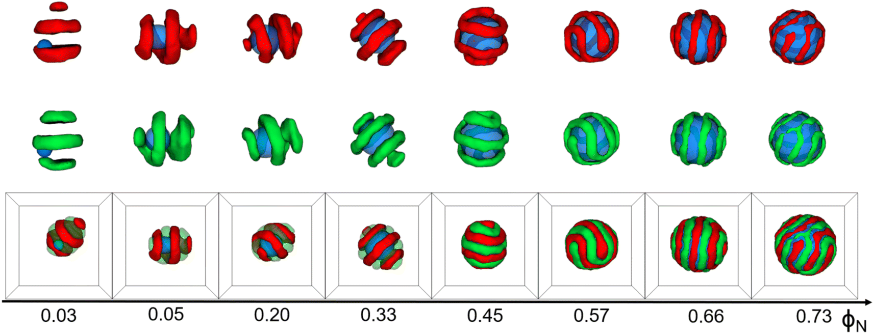 | ||
| Fig. 1 Typical core–shell particle morphologies as a function of the volume fraction of the nanoparticle to core–shell particle (ΦN) with εAB = 1.0, lA = lB = 6, C = 4%, andfA = fB = 1/2. For clarity, A/N domain or B/N domains are shown above the corresponding snapshot. Color scheme: A (red), B (green), and N (blue). | ||
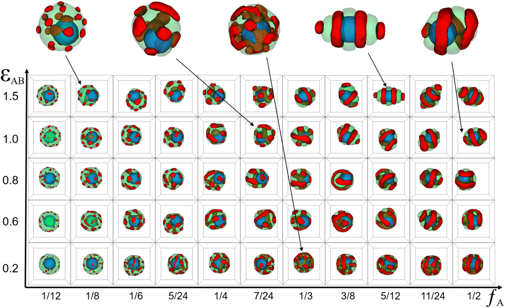 | ||
| Fig. 2 Typical core–shell particle morphologies as a function of the incompatibility between A- and B-block (εAB) and the volume fractions of A-blocks (fA) with lA + lB = 24, C = 8%, a = b = 10. The color codes are the same as that in Fig. 1. | ||
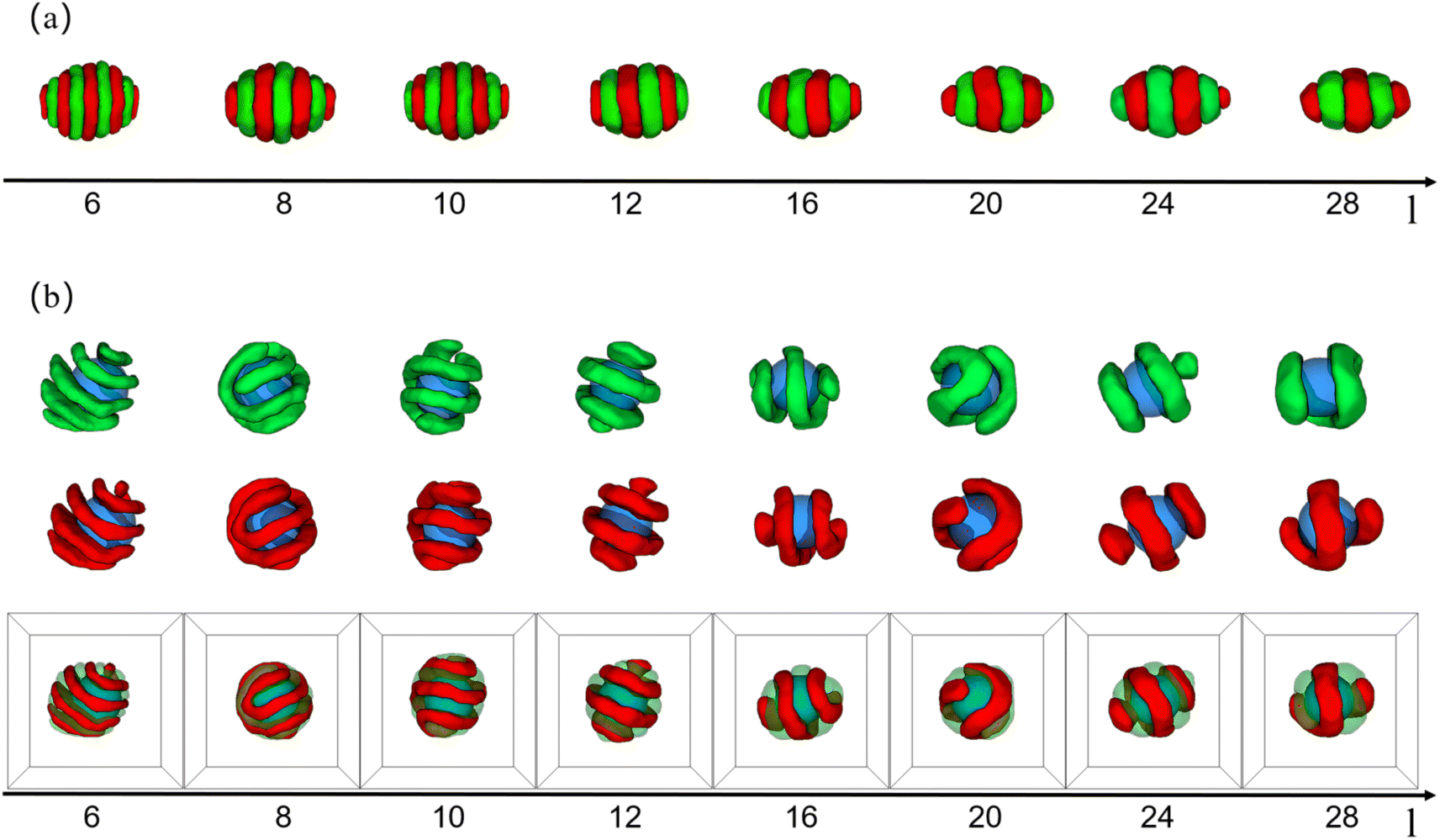 | ||
| Fig. 3 (a) Typical copolymer aggregate morphologies as a function of the whole chain length of AB diblock copolymer (l) with (εAB = 1.0), C = 5%, and fA = fB = 1/2. (b) Typical core–shell particle morphologies as a function of the whole chain length of AB diblock copolymer (l) with (εAB = 1.0), C = 5%, a = b = 10, and fA = fB = 1/2. For clarity, coloring scheme is the same as that in Fig. 1. | ||
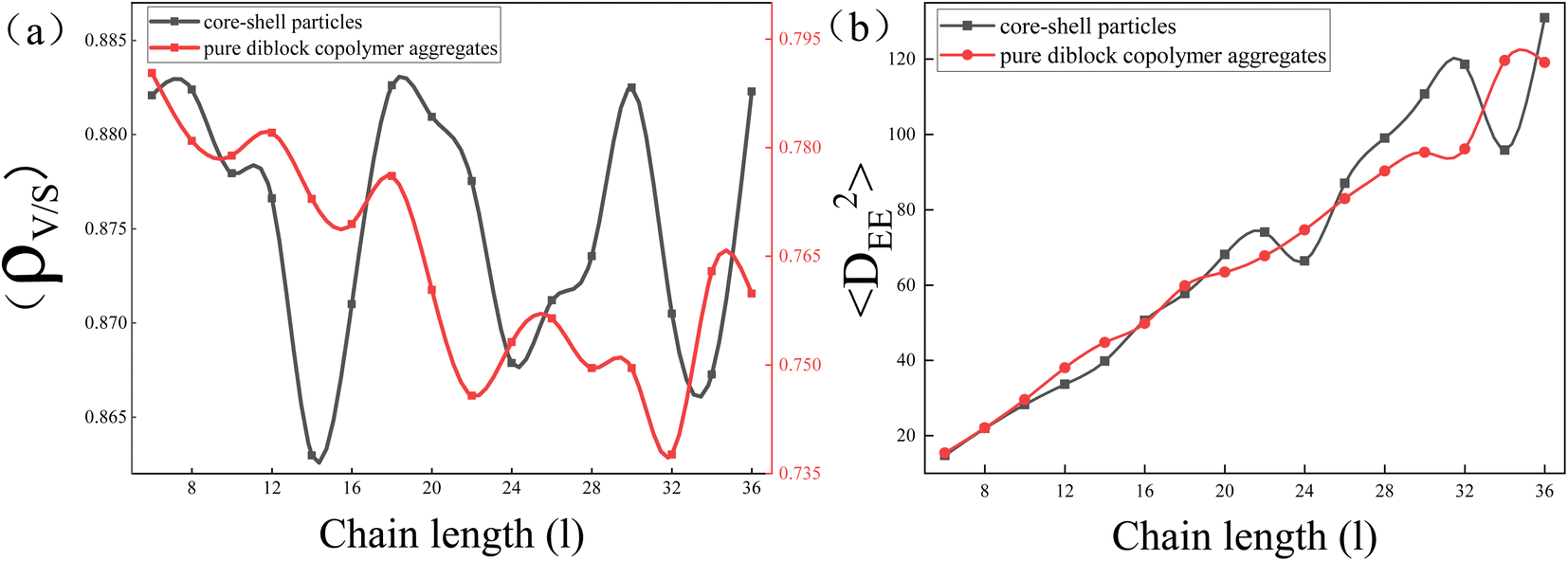 | ||
| Fig. 4 (a) The ratio of particle's volume to its surface area (ρv/s) as a function of the whole chain length of AB diblock copolymer (l). (b) The mean square end-to-end distance of the copolymer aggregates 〈DEE2〉 as a function of the whole chain length of AB diblock copolymer (l). | ||
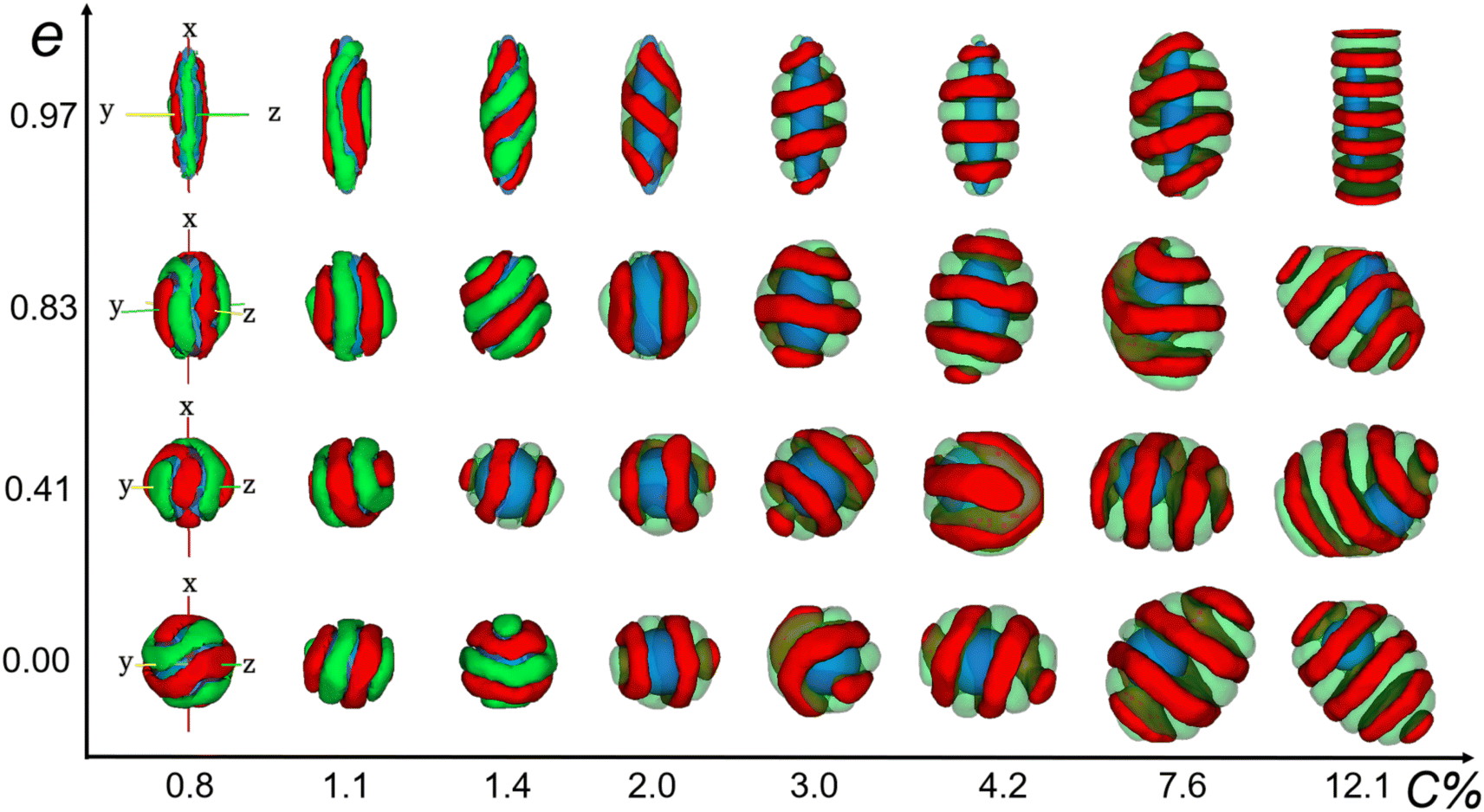 | ||
| Fig. 5 Typical core–shell particle morphologies as a function of eccentricity of nanoparticle (e) and concentration of copolymers (C%) with (εAB = 1.0), lA = lB = 6, and fA = fB = 1/2. The color codes are the same as that in Fig. 1. | ||
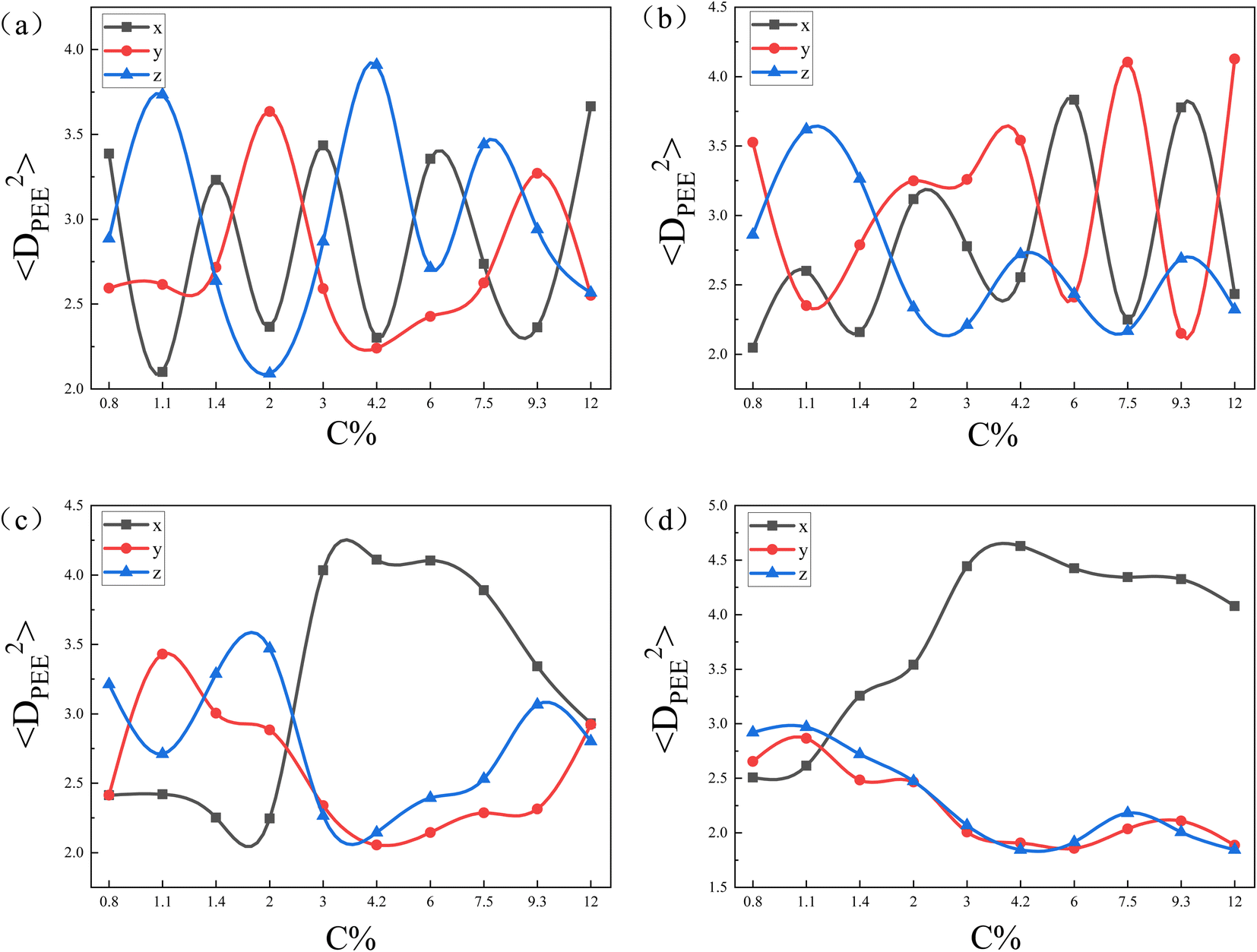 | ||
| Fig. 6 The mean square end-to-end projection distance(〈DPEE2〉) as a function of the initial concentration of copolymers (C%) for the core–shell particles in Fig. 5. The eccentricity of nanoparticle are (a); e = 0, (b); e = 0.41, (c); e = 0.83, (d); e = 0.97. | ||
Fig. 1 shows that the shape of core–shell particles gradually changed from ellipsoidal to spherical as ΦN = 0.03. Specifically, at ΦN = 0.03, AB diblock copolymers aggregated into an axially stacked lamellar structure, where the nanoparticle was embedded between the A and B domains. The morphology of the core–shell particle was consistent with that of the self-assembly of pure AB diblock copolymers in soft confinement (Fig. 3(a)), which resulted from the nanoparticle's minimal influence on the chain arrangement of AB diblock copolymers at low ΦN. It is worth mentioning that Yan et al. investigated the effect of the size of gold nanoparticles (AuNPs) on their distribution position in PS-b-P4VP ellipsoidal particles. AuNPs with small diameters were uniformly distributed in the PS domain due to their low impact on the conformational entropy of polymer chains, while those with large diameters aggregated together and distributed at the PS/solution interface because of the strong entropic repulsion between AuNPs and PS blocks.43 At ΦN = 0.05–0.20, the core–shell particles were elliptical. The A- and B-blocks formed a single helix, and the nanoparticle was fully enclosed within them. Due to the increased volume fraction of the nanoparticle (ΦN = 0.33), the long and short axes of core–shell particles decreased, but the shape of the core–shell particles remained ellipsoidal. Additionally, diblock copolymers exhibited a stacked toroid structure. At ΦN = 0.45–0.57, the core–shell particles appeared as sub-spherical shapes, with a single-helix shell. At ΦN = 0.66–0.73, core–shell particles presented as spherical, whereas the copolymers adhered in the surface of the nanoparticle, forming a spiral thin shell layer. Lin et al. created spiral spheres (3D spirals) with polypeptide-based block copolymers and homopolymers through a selective precipitation technique with the homopolymer forming the core and the copolymer forming the helix. They discovered that the chirality of the spirals can be easily modified by adjusting the preparation temperature and initial solvent properties.44 Our simulated results may provide some assistance for the preparation of ordered spiral spherical particles in soft confinement. Overall, it was found that the shape of the core–shell particles was determined by the relative volume occupied by the copolymers and the nanoparticle. When the volume of the nanoparticle was dominant, the morphology of the core–shell particle resembled that of the nanoparticle. On the other hand, when the volume of the copolymer was equivalent to that of the nanoparticle, the morphology of the core–shell particle fell between that of the pure diblock copolymer and the nanoparticle (i.e., between ellipsoidal and spherical).
Fig. 2 shows that the core–shell particles' morphology was systematically simulated by varying the incompatibility between the A- and B-blocks (εAB) and the volume fractions of the A-blocks (fA). From this morphology diagram, the 3 typical features of core–shell particles can be extracted. First, all particles exhibit a core–shell structure, with the nanoparticle as the core and copolymer aggregates as the shell. This core–shell structure was caused by (εAN=BN = −2) and (εAS=BS = 1.0). Second, the position of the nanoparticles in some core–shell particles is concentric with the copolymer aggregates, whereas in others, it is eccentric to the copolymer aggregates. A pure diblock copolymer aggregate has a certain configurational entropy, but when nanoparticles are added to it, the copolymer chains will be stretched and deflected on the surface of the nanoparticles, resulting in a loss of configurational entropy. To minimize this loss, the position of the nanoparticles varies with the initial conditions of the system, giving rise to both concentric core–shell particles and non-concentric core–shell particles. Third, the core–shell particles' shape gradually changed from spherical particles to ellipsoidal particles as fA and εAB increase. That was caused by the minimal interface energy. Specifically, at lower fA, the volume of the B-block was much greater than that of the A-block, whereas the εBS = 1.0 and εBB = 0 determined that B-blocks preferred to come into contact with themselves and reduce contact with solvents. Therefore, the core–shell particles were spherical (the smallest surface area for the same volume). At fA = fB, copolymer aggregates with equal volumes of A- and B-blocks tended to form multi-layer structures. In addition, as εAB increased, copolymer aggregates reduced the lamellae area to reduce contact between A- and B- blocks. While in the process of reducing the lamellae area, AB diblock copolymer aggregates changed from spherical to ellipsoidal, but that was unfavourable in reducing the interface energy between the blocks and the solvent. Therefore, the interfacial energy between A- and B-blocks and the interface energy between the blocks and the solvent formed the main competing factors affecting the formation of a copolymer aggregate structure. Briefly, the larger the degree to which (εAB < εAS), the closer the particle was to a sphere with lower eccentricity, and the larger the degree to which (εAB > εAS), the closer the particle was to an ellipsoid with higher eccentricity. Simultaneously, the self-assembled morphology of diblock copolymers in soft-hard confinement exhibited structural features in the bulk. The phase behavior of diblock copolymers in the bulk is distinguished by the arrangement of copolymer chains and the resulting ordered structures, including the spherical phase, cylindrical phase, gyroid phase, and lamellar phase.45 For convenience, the fA and εAB represent the horizontal and vertical coordinates of the particle in the morphology diagram, respectively. At (1/8, 1.5), the copolymer shell was formed by droplet-like A-domains embedding into the B matrix. A small number of A-droplets were distributed between the surface of the nanoparticles and the B-matrix, while most of the A-droplets were distributed between the B-matrix and the solvents. The droplet-like domains were characteristic of the sphere phase in bulk. It is worth noting that Staff et al. added hydrophobic hexadecane to poly(vinylferrocene)-block-poly(methyl methacrylate) (PVFc-b-PMMA) and prepared patchy nanocapsules with PVFc-b-PMMA as shells and hexadecane as cores by an emulsion volatilization method.2 The PVFc-b-PMMA shell of the patchy capsule essentially matches the core–shell particles in the sphere region of our simulations, both in terms of copolymer structure and block volume fraction. At (7/24, 1.0), the copolymer shell adopts an ellipsoidal shape, with A-blocks embedded in the B-matrix in the form of droplets, pancakes, a triple-fold junction, and short arcs. This phenomenon arises from several factors, including the reduced surface area of the nanoparticle compared to core–shell particles, an increased volume fraction of the A-blocks, and the impact of soft confinement. Specifically, the smaller surface of the nanoparticle led to the convergence of internal droplets to form a triple-fold junction, the increasing volume fraction of A-blocks resulted in the merging of external droplets to form pancakes, and the soft-confined environment caused the bending of longer pancakes to form short arcs. The short arc and triple-fold junction corresponded to the cylindrical and gyroid phase in bulk, respectively. At (1/3, 0.2), the copolymer shell exhibited disorganized A and B domains, attributed to the slight incompatibility between the blocks. At (5/12, 1.5) and (1/2, 1.0), the copolymer shell featured alternately arranged A and B domains in the form of a single helix and a stacked ring structure, respectively, reflecting the symmetric and alternating domain structure characteristic of the lamellar phase in bulk.
Because the chain length of copolymers (l) had an important effect on the elongation of pure copolymer aggregates,11 we wondered whether the chain length had the same effect on core–shell particles formed by the co-assembly of AB diblock copolymers and nanoparticle. Therefore, in addition to simulating the morphology sequence of the core–shell particles, we also simulated the pure copolymer aggregates as a control group, as shown in Fig. 3. In the case of pure copolymer aggregates, the copolymer aggregates took on an ellipsoidal shape. With increasing l, the ellipsoidal copolymer aggregates tended to flatten and elongate, accompanied by a reduction in the number of lamellae. That simulation result was basically consistent with the experimental results. The nanoparticle was added in neutral soft confinement based on pure diblock copolymers. The elongation of the core–shell particles is not monotonically increasing compared to the control as shown in Fig. 3(b). For instance, the core–shell particles at l = 8 and 20 display a spherical shape, while the core–shell particles at l = 6 and 24 appear to have the longer elongation. Those core–shell particles formed a typical core–shell structure, where the copolymer shell had various structures including a single helix, double helices, stacked toroids, and a saddle toroid and an arc(at l = 20). Notably, as l increased, the helix structure's pitch widened, the helix's line length shortened, and the number of stacked toroids increased. Those features were essentially the same as pure copolymer aggregates that reduced the number of lamellae as l increased.
To explore the reason behind the nonmonotonic change in elongation of the core–shell particles with increasing l, the ratio of particle's volume to its surface area (ρv/s) and the mean square end-to-end distance of the copolymer chains 〈DEE2〉 were calculated (Fig. 4(a) and (b) respectively). It is well known that the surface area of a sphere is the smallest for the same volume, so the larger the ρv/s of a particle is, the closer it is to a sphere with equal lengths and short axes, whereas the smaller the ρv/s of a particle is, the greater the difference between the lengths and the short axes. Here, we used that value to denote the change in elongation of the particles. Comparing the ρv/s range of core–shell particles and pure copolymer aggregates, it was found that the ρv/s range of the core–shell particles was 0.860 to 0.885, whereas the ρv/s range of the pure copolymer aggregates was 0.735 to 0.795. That indicated that adding nanoparticles can overall reduce the elongation of copolymer aggregates. From the red line, it can be observed that the ρv/s of pure diblock copolymer aggregates decreased in a wave-like manner with the increase in l, indicating that the particle elongation continued to increase, consistent with the experimental results.11 From the black line, it can be seen that the ρv/s of core–shell particles fluctuated up and down in a sinusoidal-like function as l increases, and at l = 18, 20, 30, and 36, the ρv/s ratio of core–shell particles was basically equal with l = 3 and 4. That means that the elongation of the core–shell particles varied stochastically with the increase of l. In Fig. 4(b), comparing 〈DEE2〉 between core–shell particles and pure diblock copolymer aggregates, it can be seen that they essentially coincide in the short molecular chain. However, in the long molecular chain, the undulation fluctuation of the two was significantly greater, with the 〈DEE2〉 of the core–shell particles slightly exceeding that of the pure diblock copolymer. Those features indicate that long molecular chains are more easily stretched or compressed than short chains. Comparing Fig. 4(a) and (b), it was found that in the case of long molecular chains, the peak of ρv/s of the core–shell particles had the same trend as the peak of 〈DEE2〉 of the core–shell particles. That means that the stretching or compression of long molecular chains played an important role in controlling the elongation of core–shell particles. Note that Daniel Klinger et al. found that the greater energy loss in short-chain stretching than in long-chain stretching is an important reason for the increase in elongation with increasing molecular weight of ellipsoidal particles formed by self-assembly of diblock copolymers under neutral soft confinement.11
Xiang et al. studied the self-assembly of PS-b-PBD diblock copolymers under cylindrical geometric confinement. It was found that under weak confinement, the morphology of diblock copolymers was basically the same as that of the bulk. Under strong confinement, due to the curvature and irreducibility of the cylindrical surface, diblock copolymers with a cylinder structure in bulk were forced to form a helical structure.46 Hence, we wanted to know how hard-wall surfaces with a certain curvature affect the arrangement of copolymer chains in 3D soft confinement. By varying the eccentricity of the nanoparticle (e) and the initial concentration of diblock copolymers (C%), a morphology diagram was created, as shown in Fig. 5. In morphology diagram, we can observe that the structure and spatial arrangement of the copolymer domains show a strong correlation with the eccentricity of the nanoparticle as well as the initial concentration of the copolymers. For convenience, the C% and e values represent the horizontal and vertical coordinates of the particle in the morphology diagram, respectively. First, at (0.8,0), (1.4,0), (7.6,0),the A- and B-domains were predominantly oriented perpendicular to the x-axis of the nanoparticle. At (1.1,0), (2.0,0), (4.2,0), the A- and B-domains were oriented predominantly parallel to the x-axis of the nanoparticle. At (3,0), (12.1,0), the A- and B-domains were oriented at an approximately 45° angle to the x-axis. That observation indicated that the orientation of the A- and B-domains on the nanoparticle's surface had a certain randomness, a characteristic attributed to the isotropic nature of the nanoparticle. Second, from (0.8,0) → (0.8, 0.41) → (0.8,0.83) → (0.8,0.97), the degree of alignment of the A- and B-domains along the x-axis increased with the increase in the eccentricity of the nanoparticle. Copolymer chains tended to align along the direction of greater curvature not only to adapt to their own curvature but also to maintain a guaranteed low chain stretch. Notably, at (1.1, 0.97), the A- and B-domains near the endpoints of the nanoparticles were deflected in the circumference direction and were no longer aligned exactly along the x-axis. That deflection was caused by the curvature gradient along the x-axis near the endpoints decreasing to the same extent as the curvature gradient along the circumference direction of the nanoparticle. Third, from (0.8,0.97) → (1.4,0.97) → (3.0,0.97),the copolymer shell changed from striped structure to double helices structure then to single helix structure. That was because as the C% increased, if the A- and B-domains continued to align along the x-axis direction of the nanoparticle, the outer copolymer chains would be stretched infinitely with increasing thickness, resulting in a significant entropy loss. Hence, the A- and B-domains were no longer aligned along the x-axis direction of the nanoparticle but were instead aligned along the x-axis deflected by an angle. The copolymer chains' regular deflection on the nanoparticles'surfaces added to the helical structure. Although that choice sacrificed some conformational entropy of the inner chains, it prevented the outer chains from being excessively stretched. Overall, there was an equilibrium in the conformational entropy of the copolymer chains in the competition between the inner and outer chains. Hence, the A- and B-domains were no longer aligned along the x-axis direction of the nanoparticle but were instead aligned along the x-axis deflected by an angle. Last, at (7.6,0.83), (7.6,0.41), (12.1,0.83), and (12.1,0.41), we can clearly observe that the core–shell particles were not exactly lamellae but formed a single-helix structure in some localized regions. The position of the nanoparticles at the edges of the overall core–shell particles made the concentration of copolymer distributed around the nanoparticles inhomogeneous. Briefly, the copolymer shell layer thickness surrounding the nanoparticles varied, with thicker areas having a higher copolymer concentration and thinner areas having a lower concentration. At higher concentrations, the copolymer chains were less affected by the nanoparticle and formed lamellar structures to avoid overstretching of the chains, whereas at lower concentrations, the copolymer chains were more affected by the curvature of the nanoparticles, and the chains were deflected and formed helical structures locally. Eventually, A- and B-domains away from the nanoparticle adopted a lamellar structure, whereas A- and B-domains near the nanoparticle adopted a helical structure.
To further confirm our idea, we calculated the mean square end-to-end projection distance (〈DPEE2〉) in the x-, y-, and z-directions, as shown in Fig. 6. Fig. 6(a) and (b) shows that as C% increased, 〈DPEE2〉 in the 3 directions varied randomly. That provided evidence that when the curvatures of the nanoparticles were the same in all directions, the copolymer chains did not exhibit specificity in the direction of deflection. Notably, the curvature of nanoparticles' surfaces shows variation in different directions based on the eccentricity of nanoparticles. For instance, at e = 0, uniform curvature was observed in all three directions. Conversely, when e = 0.97, the nanoparticles displayed a smaller curvature in the x-direction compared to the y- and z-directions. The greater the eccentricity of the nanoparticles, the more pronounced the difference in surface curvature of the nanoparticles in three directions. In Fig. 6(c) and (d), 〈DPEE2〉 in the y- and z-directions were larger than 〈DPEE2〉 in the x-direction for concentrations below 2.0 and 1.1, respectively. Those observations validated that at low concentrations, the copolymer chains tend to align along the direction of greater nanoparticle curvature. On the other hand, it was noted that the concentration point where 〈DPEE2〉 on the x-axis exceeded that on the y- and z-axes shifted from 2.0 to 1.1 as seen in Fig. 6(c) and (d). That happened because the copolymer chains could align naturally on the nanoparticle's surface with low eccentricity when the shell layer was thin. However, as the concentration increased, the copolymer shell layer became thicker, and the lower the eccentricity of the nanoparticles, the greater the increase in copolymer chain stretching. Therefore, the lower the eccentricity of the nanoparticles, the sooner the copolymer chains adjusted to minimize the loss of conformational entropy. That adjustment also resulted in the concentration point shifting forward.
3 Conclusions
In summary, core–shell particle formation via co-assembly of AB diblock copolymers and nanoparticles in 3D soft confinement were studied using a simulated annealing method. We predicted core–shell particles with various core–shell structures, as well as analysed the formation mechanisms of the internal structures of those core–shell particles. The overall shape of the core–shell particles depended on the volume ratio between the copolymers and the nanoparticle. When the volume of the nanoparticle dominated, the core–shell particles were spherical; when the volume of the copolymer dominated, the core–shell particles were elongated ellipsoids; when the volumes of the two were comparable, the shapes of the core–shell particles lay between spheres and elongated ellipsoids. By changing the incompatibility between the A and B blocks and the volume fraction of the A block, a morphology diagram that exhibits structural characteristics in the bulk phase was observed. Unlike in bulk, the influence of soft–hard confined walls enabled core–shell particles to exhibit multiple characteristics of bulk simultaneously, a typical copolymer shell with small droplets, short cylinder, and triple junctions. Due to the easily stretchable nature of long molecular chains, the elongation of core–shell particles did not monotonically increase with the increase in chain length. At low concentrations, copolymer chains tended to align in the direction where the curvature gradient of the nanoparticles decreased more rapidly. At high concentrations, copolymer chains aggregated on nanoparticles'surface to form a non-uniform shell layer. The thin shell layer was greatly influenced by hard confinement walls from nanoparticles, forming a helix structure. The thick shell layer was significantly impacted by soft confinement walls from poor solvents, forming a lamellar structure.Data availability
All data used in this study are available upon reasonable request. If you wish to obtain the data, please contact the author at [E-mail: 107552100702@stu.xju.edu.cn]. We will provide the requested data as soon as possible upon receiving the request.Author contributions
Liangjun Ma(first author), completed the computational simulation, principle analysis, and paper writing work of this paper. Weixing Kong(Corresponding author), completed the design and modification of the simulation program for this paper, guiding the principles, and revising the paper.Conflicts of interest
There is no conflict of interests regarding the publication of this article.Acknowledgements
This work was supported by the National Natural Science Fund of China (21304078) and (21863010).Notes and references
- R. H. Staff, P. Rupper, I. Lieberwirth, K. Landfester and D. Crespy, Soft Matter, 2011, 7, 10219–10226 RSC.
- R. H. Staff, M. Gallei, M. Mazurowski, M. Rehahn, R. Berger, K. Landfester and D. Crespy, ACS Nano, 2012, 6, 9042–9049 CrossRef CAS.
- R. Deng, M. J. Derry, C. J. Mable, Y. Ning and S. P. Armes, J. Am. Chem. Soc., 2017, 139, 7616–7623 CrossRef CAS PubMed.
- M. Hussain, J. Xie, Z. Hou, K. Shezad, J. Xu, K. Wang, Y. Gao, L. Shen and J. Zhu, ACS Appl. Mater. Interfaces, 2017, 9, 14391–14400 CrossRef CAS.
- K. H. Ku, J. M. Shin, D. Klinger, S. G. Jang, R. C. Hayward, C. J. Hawker and B. J. Kim, ACS Nano, 2016, 10, 5243–5251 CrossRef CAS.
- M.-K. Park, S. Jun, I. Kim, S.-M. Jin, J.-G. Kim, T. J. Shin and E. Lee, Adv. Funct. Mater., 2015, 25, 4570–4579 CrossRef CAS.
- J. Xu, J. Li, Y. Yang, K. Wang, N. Xu, J. Li, R. Liang, L. Shen, X. Xie and J. Tao, et al., Angew. Chem., Int. Ed., 2016, 55, 14633–14637 CrossRef CAS.
- Y. Zhao, R. Berger, K. Landfester and D. Crespy, Small, 2015, 11, 2995–2999 CrossRef CAS.
- E. Pisani, N. Tsapis, B. Galaz, M. Santin, R. Berti, N. Taulier, E. Kurtisovski, O. Lucidarme, M. Ourevitch and B. T. Doan, et al., Adv. Funct. Mater., 2008, 18, 2963–2971 CrossRef CAS.
- J. Xu, Y. Wu, K. Wang, L. Shen, X. Xie and J. Zhu, Soft Matter, 2016, 12, 3683–3687 RSC.
- D. Klinger, C. X. Wang, L. A. Connal, D. J. Audus, S. G. Jang, S. Kraemer, K. L. Killops, G. H. Fredrickson, E. J. Kramer and C. J. Hawker, Angew. Chem., 2014, 126, 7138–7142 CrossRef.
- T. Higuchi, A. Tajima, K. Motoyoshi, H. Yabu and M. Shimomura, Angew. Chem., Int. Ed., 2008, 47, 8044–8046 CrossRef CAS PubMed.
- Z. Wang, Y. Cao, X. Zhang, D. Wang, M. Liu, Z. Xie and Y. Wang, Langmuir, 2016, 32, 13517–13524 CrossRef CAS PubMed.
- R. Deng, H. Li, J. Zhu, B. Li, F. Liang, F. Jia, X. Qu and Z. Yang, Macromolecules, 2016, 49, 1362–1368 CrossRef CAS.
- N. Yan, Y. Zhu and W. Jiang, J. Phys. Chem. B, 2016, 120, 12023–12029 CrossRef CAS.
- R. Deng, H. Li, F. Liang, J. Zhu, B. Li, X. Xie and Z. Yang, Macromolecules, 2015, 48, 5855–5860 CrossRef CAS.
- K. H. Ku, Y. Kim, G.-R. Yi, Y. S. Jung and B. J. Kim, ACS Nano, 2015, 9, 11333–11341 CrossRef CAS PubMed.
- S.-J. Jeon, G.-R. Yi, C. M. Koo and S.-M. Yang, Macromolecules, 2007, 40, 8430–8439 CrossRef CAS.
- T. Higuchi, K. Motoyoshi, H. Sugimori, H. Jinnai, H. Yabu and M. Shimomura, Soft Matter, 2012, 8, 3791–3797 RSC.
- J. M. Shin, M. P. Kim, H. Yang, K. H. Ku, S. G. Jang, K. H. Youm, G.-R. Yi and B. J. Kim, Chem. Mater., 2015, 27, 6314–6321 CrossRef CAS.
- C. Chen, Z. Xiao and L. A. Connal, Aust. J. Chem., 2016, 69, 741–745 CrossRef CAS.
- R. Deng, F. Liang, W. Li, Z. Yang and J. Zhu, Macromolecules, 2013, 46, 7012–7017 CrossRef CAS.
- J. Xu, K. Wang, J. Li, H. Zhou, X. Xie and J. Zhu, Macromolecules, 2015, 48, 2628–2636 CrossRef CAS.
- J. Xu, Y. Yang, K. Wang, Y. Wu and J. Zhu, Mater. Chem. Front., 2017, 1, 507–511 RSC.
- T. Higuchi, K. Motoyoshi, H. Sugimori, H. Jinnai, H. Yabu and M. Shimomura, Macromol. Rapid Commun., 2010, 31, 1773–1778 CrossRef CAS PubMed.
- J. M. Shin, Y. Kim, H. Yun, G.-R. Yi and B. J. Kim, ACS Nano, 2017, 11, 2133–2142 CrossRef CAS.
- L. Li, K. Matsunaga, J. Zhu, T. Higuchi, H. Yabu, M. Shimomura, H. Jinnai, R. C. Hayward and T. P. Russell, Macromolecules, 2010, 43, 7807–7812 CrossRef CAS.
- T. Higuchi, M. Shimomura and H. Yabu, Macromolecules, 2013, 46, 4064–4068 CrossRef CAS.
- S. Liu, R. Deng, L. Shen, X. Xie and J. Zhu, Macromolecules, 2015, 48, 5944–5950 CrossRef CAS.
- S. Lee, J. J. Shin, K. H. Ku, Y. J. Lee, S. G. Jang, H. Yun and B. J. Kim, Macromolecules, 2020, 53, 7198–7206 CrossRef CAS.
- J. Zhu and R. C. Hayward, Angew. Chem., 2008, 120, 2143–2146 CrossRef.
- J. Zhu, N. Ferrer and R. C. Hayward, Soft Matter, 2009, 5, 2471–2478 RSC.
- J. Zhu and R. C. Hayward, J. Am. Chem. Soc., 2008, 130, 7496–7502 CrossRef CAS PubMed.
- S. Liu, R. Deng, W. Li and J. Zhu, Adv. Funct. Mater., 2012, 22, 1692–1697 CrossRef CAS.
- R. Deng, S. Liu, F. Liang, K. Wang, J. Zhu and Z. Yang, Macromolecules, 2014, 47, 3701–3707 CrossRef CAS.
- S. G. Jang, D. J. Audus, D. Klinger, D. V. Krogstad, B. J. Kim, A. Cameron, S.-W. Kim, K. T. Delaney, S.-M. Hur and K. L. Killops, et al., J. Am. Chem. Soc., 2013, 135, 6649–6657 CrossRef CAS PubMed.
- S. Kirkpatrick, C. D. Gelatt Jr and M. P. Vecchi, science, 1983, 220, 671–680 CrossRef CAS PubMed.
- G. S. Grest, C. Soukoulis and K. Levin, Phys. Rev. Lett., 1986, 56, 1148 CrossRef.
- I. Carmesin and K. Kremer, Macromolecules, 1988, 21, 2819–2823 CrossRef CAS.
- W. Kong, B. Li, Q. Jin, D. Ding and A.-C. Shi, J. Am. Chem. Soc., 2009, 131, 8503–8512 CrossRef CAS.
- B. Yu, P. Sun, T. Chen, Q. Jin, D. Ding, B. Li and A.-C. Shi, Phys. Rev. Lett., 2006, 96, 138306 CrossRef PubMed.
- N. Metropolis, A. W. Rosenbluth, M. N. Rosenbluth, A. H. Teller and E. Teller, J. Chem. Phys., 1953, 21, 1087–1092 CrossRef CAS.
- N. Yan, H. Liu, Y. Zhu, W. Jiang and Z. Dong, Macromolecules, 2015, 48, 5980–5987 CrossRef CAS.
- W. Xu, Z. Xu, C. Cai, J. Lin, L. Gao, H. Qi and S. Lin, Nanoscale, 2021, 13, 14016–14022 RSC.
- F. S. Bates and G. H. Fredrickson, Phys. Today, 1999, 52, 32–38 CrossRef CAS.
- H. Xiang, K. Shin, T. Kim, S. Moon, T. McCarthy and T. Russell, J. Polym. Sci., Part B: Polym. Phys., 2005, 43, 3377–3383 CrossRef CAS.
| This journal is © The Royal Society of Chemistry 2024 |