
 Open Access Article
 This Open Access Article is licensed under a Creative Commons Attribution-Non Commercial 3.0 Unported Licence
The effects of crystal structure on the chemical durability of yttrium disilicate
Keith Bryce a,
Kun Yanga,
Mingxin Lia,
Dong Zhaoa and
Jie Lian*ab
a,
Kun Yanga,
Mingxin Lia,
Dong Zhaoa and
Jie Lian*ab
aDepartment of Mechanical, Aerospace, and Nuclear Engineering, Rensselaer Polytechnic Institute, NY 12180, USA
bDepartment of Materials Science & Engineering, Rensselaer Polytechnic Institute, NY 12180, USA. E-mail: lianj@rpi.edu
First published on 29th April 2024
Abstract
Amorphous, α, β, and γ-phase yttrium disilicate Y2Si2O7 pellets were synthesized by spark plasma sintering, and their chemical durability and degradation mechanisms were investigated via semi-dynamic leaching test in pH = 3 nitric acid at 90 °C. All crystalline phases displayed relatively congruent dissolution with a slight preferential release of Y. The amorphous sample showed clear incongruent dissolution with preferential release of Y, leading to a surface reorganization reaction and the formation of a SiO2 passivation layer 20–25 μm thick on the surface of the sample. This passivation layer led to a continuous decrease in the elemental release rates of the amorphous sample. The γ-phase sample displayed the lowest short-term and long-term leaching rates of Y and Si, followed by the β, α, and then amorphous sample. The crystalline samples showed increasing release rates over time indicating a dissolution-controlled reaction mechanism. Post-leaching microstructural characterization of the β and γ samples revealed variations in the corrosion levels of the surface grains, indicating a dependence on grain orientation.
1. Introduction
The disposal of nuclear waste is a key aspect of the nuclear fuel cycle and a complex issue that requires the use of metal, glass, and ceramic materials for the immobilization of long-lived radionuclides. The use of deep geological repositories has been the general consensus for the isolation and disposal of high-level nuclear waste, and once spent fuel is removed from the reactor, cooled and separated into appropriate waste streams, they may be combined with various additives to produce waste glasses and ceramics which are then sealed in stainless steel canisters and placed in a repository.1 One of the long-term concerns associated with geological repositories is the possible interaction between the stored waste and ground water.2 Hence, the long-term understanding of the phase stability and chemical durability of these ceramics is critical for the safe disposition of nuclear waste and to prevent the release of radionuclides into biosphere.3The chemical durability of mineral for nuclear waste form application has been the topic of intense studies.4–10 One of the more widely studied waste ceramics is SYNROC, a multiphase combination of minerals such as zirconolite, pyrochlore, perovskite, and hollandite, created by mixing radioactive waste oxides with inert oxides such as titanium oxide and hot-pressing the mixture in a sealed metal container to create a dense and compact material.11 Rare-earth disilicates are another group of ceramics that have been investigated for their nuclear waste immobilization application, not as a direct host matrix but rather a secondary barrier for immobilization that may be formed from the combination of rare-earth solution and smectite found in clay barriers under geological repository conditions.12–14 Rare-earth elements (REE) may be used as surrogates for actinides, hence understanding the corrosion mechanism and phase stability of rare-earth disilicates could aid in predicting their long-term retention of actinide ions. However, rare-earth disilicates are more widely studied due to their luminescence properties, particularly for crystal scintillator applications,15,16 and much attention has been given to their potential application as environmental barrier coatings due to their high mechanical strength, low thermal conductivity, and the ranges of their thermal expansion coefficients.17–19 Polymorphism is common amongst the RE disilicates as they exhibit seven different structural phases at ambient pressures, type A (P41, tetragonal), type B/α (P![[1 with combining macron]](https://www.rsc.org/images/entities/char_0031_0304.gif) , triclinic), type C/β (C2/m, monoclinic), type D/γ (P21/a, monoclinic), type E/δ (Pnam, orthorhombic), type F (P, triclinic), and type G (P21/c, monoclinic).20 Amongst the rare-earth disilicates, Y2Si2O7 exhibits the most structural phases: α, β, γ, and δ. Their phase transformation temperatures, as reported by Ito (1968), are as follows: the alpha to beta transformation temperature is 1225 °C, the beta to gamma transformation temperature is 1445 °C, and the gamma to delta transformation temperature is 1535 °C.21
, triclinic), type C/β (C2/m, monoclinic), type D/γ (P21/a, monoclinic), type E/δ (Pnam, orthorhombic), type F (P, triclinic), and type G (P21/c, monoclinic).20 Amongst the rare-earth disilicates, Y2Si2O7 exhibits the most structural phases: α, β, γ, and δ. Their phase transformation temperatures, as reported by Ito (1968), are as follows: the alpha to beta transformation temperature is 1225 °C, the beta to gamma transformation temperature is 1445 °C, and the gamma to delta transformation temperature is 1535 °C.21
There is an additional low-temperature y-phase which is thought to be a complex silicate with an approximate formula R(Y, RE)5Si6O21, where R represents stabilizing impurities such as H+, Na+, Mg2+, Mn2+, Fe2+, Fe3+, Al3+, Th4+ and Zr4+.21 The α-phase has a structure characterized by an isolated chain-like group [Si3O10]8− comprised of three corner-sharing [SiO4]4− tetrahedral groups plus an additional [SiO4]4− tetrahedral, which is unique to this phase specifically.22 These silicate groups are linked by the Y3+ cations occupying the interspaces between them with the unit cell having four different Si sites and four different Y sites in terms of coordination number and bond angles. Three of the four Y3+ cations are each coordinated to eight oxygen atoms while the fourth is coordinated to six oxygen atoms as indicated in Fig. 1(a). The structure of the β-phase consists of [Si2O7]6− groups each comprised of two corner-sharing [SiO4]4− tetrahedral groups with the connecting Si–O–Si bond having an angle of 180°.23 The Y3+ cations occupy the distorted octahedral interspace between the [Si2O7]6− groups, coordinating with all the oxygen atoms of [Si2O7]6− groups except for the bridging oxygen.23 Overall, this phase contains one unique Si site and one unique Y site and can be depicted as layered-like stacking of [YO6]9− octahedrons on top of [Si2O7]6− polyhedrons as indicated in Fig. 1(b). Similar to the β-phase, the γ-phase consist of [Si2O7]6− groups made of two corner-sharing [SiO4]4− tetrahedral groups the main difference being that the Si–O–Si bond angle is around 172° for this phase.24 Like the β-phase, the γ-phase has one unique Si site and one unique Y site with the Y3+ cations showing octahedral coordination and the bridging oxygens not participating in the Y3+ coordination. This phase can be described as wave-like layered stacking of the [YO6]9− octahedrons and [Si2O7]6− polyhedrons as indicated in Fig. 1(c).
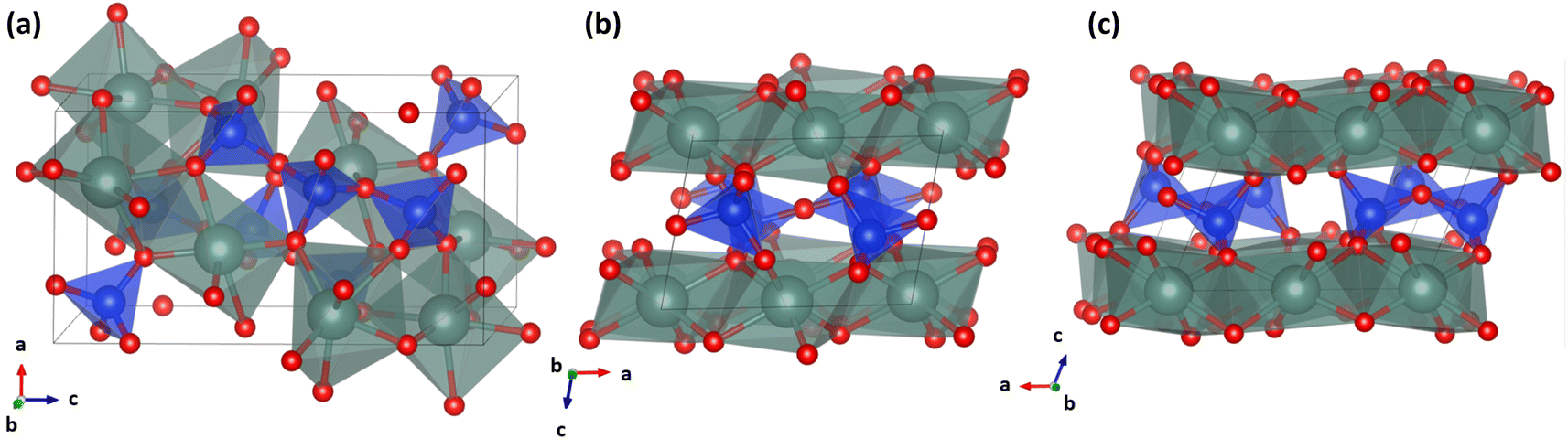 | ||
| Fig. 1 . Diagrams of the α, β, and γ-phase Y2Si2O7 structures. The green, blue, and red spheres represent Y, Si, and oxygen atoms, respectively. | ||
The chemical durability of waste form materials is generally measured via laboratory scale leaching tests which can vary widely in protocol. Galunin et al. (2011) investigated the relative elemental release of β-phase Sc, Lu, and Y2Si2O7 via pH leaching test in HNO3 and NaOH solutions with varied pH values from 1 to 13 at room temperature for 7 days.12 It was observed that the leaching rates of both the REEs and Si decreased with the ionic radius of the REE in the rare-earth disilicates, indicating increased chemical stability with decreasing size of the REEs. The chemical durability of Y2Si2O7 has also been studied. Specifically, Galunin et al. (2011) measured the relative elemental releases of the α, β, γ, and δ-phases in HNO3 and NaOH solutions with pH values of 1–13 solutions for 7 days.25 The results showed that the leaching rate increased in the order δ < γ < β < α, indicating increased stability with the increase in formation temperature of the respective phase. While these studies shed light on the corrosion reaction of rare earth disilicates, the corrosion mechanisms and microstructural evolution of the materials were not investigated or discussed, and the leaching rates were not reported. In the case of the more studied waste form materials such as pyrochlores and zirconates, Yang et al. (2021) reported lanthanide leaching rates of (1–10 mg m−2 d−1) and (1 × 10⁻⁶–23 mg m−2 d−1) for titanate pyrochlores and zirconate fluorites respectively as well as the formation various surface passivation layers following semi dynamic leaching for 14 days at 90 °C in pH 1 nitric acid.26,27
In the present work, amorphous, α, β, and γ-phase Y2Si2O7 pellets are synthesized, and their corrosion resistance is measured via semi-dynamic leaching test for 14 days at 90 °C in pH 3 nitric acid. A semi-dynamic leaching protocol was used to avoid solution saturation particularly at the initial stage of the leaching test, while the leaching test is carried out at 90 °C in pH 3 nitric acid to accelerate the rate of leaching relative to more realistic conditions.28 The δ-phase polymorph was excluded from this study as the synthesis of a pure δ-phase was never achieved even at sintering temperatures of 1625 °C. All samples were synthesized via solid-state reaction and Spark Plasma Sintering (SPS), with comparable grain sizes (except for the amorphous sample). All the samples were tested under the same accelerated leaching conditions, to better understand the leaching mechanism and the properties of each phase that contribute to their relative stability. A series of pre- and post-leaching microstructural characterizations, along with the measured elemental release rates of Y and Si, were utilized to analyze the chemical durability and corrosion mechanism of each phase of Y2Si2O7.
2. Experimental methods
2.1 Powder synthesis and pellet sintering
Y2Si2O7 powders were synthesized through the solid-state reaction of the precursor powders Y2O3 (Sigma Aldrich) and SiO2 (Sigma Aldrich) mixed in the appropriate stoichiometric ratio. The mixed powders were combined with pure ethanol in a 1 g of mixed powders to 1.5 mL of ethanol ratio and ball-milled using a high energy ball milling equipment (Pulverisette-7, FRITSCH, German) using ZrO2 grinding media. The ball milling process was carried out for 40 cycles at 500 rpm, each cycle being 30 minutes with a 10 pause between each cycle to prevent overheating of the mixture. Once completed, the obtained slurry was dried in a furnace at 90 °C for 12 hours to remove any ethanol from the mixer. The pellets for all three phases and the amorphous sample were sintered by SPS sintering using a Model 10–3 SPS system (Thermal Tech, LLC, Santa Rosa, California). The Y2Si2O7 powders were first loaded inside a graphite die (8 mm inner diameter) which was coated on the inside with a graphite foil (0.2 mm thick) to act as a buffer between the die and the powders. A thick graphite coating is placed around the die before the sintering process to provide additional thermal insulation during sintering. Sintering was carried out in an argon atmosphere with a constant 1 L min−1 flow of argon gas purging the sintering chamber. During the sintering process, uniaxial pressure was applied at a rate of 8.25 MPa min−1 from an initial 15 MPa to a dwelling pressure of 40 MPa, and the temperature was increased at a rate of 200 °C min−1 from 25 °C to the respective dwelling temperature. The α, β, γ, and amorphous pellets were sintered at temperatures of 1200 °C, 1350 °C, 1500 °C, and 650 °C, respectively, and held at a dwell time of 15 minutes, after which the pellets were allowed to cool down to room temperature while under the constant 1 L min−1 flow of argon gas. Additionally, the α-phase pellet was annealed in air at 1100 °C for 144 hours to increase its grain size. After completion of the sintering process, the pellets were ground with an abrasive SiC paper to remove excess graphite foil and then polished to a mirror finish. The polish was done by first using higher grit SiC papers with water as the polishing agent, except for the amorphous pellet where ethanol was used instead, and then finally polished using (0.06 μm silica colloidal) paste on an appropriate polishing cloth. The pellets were then cleaned using deionized water in an ultrasonic cleaner to remove any excess silica from their surface.2.2 Phase and microstructure characterization
After polishing, the phase compositions of the pellets were characterized using X-ray diffraction (XRD) by a Panalytical X'Pert Pro system (Westborough, MA, USA) with a copper target (Kα = 0.15406 nm) and a step size of 0.013° 2θ. The bulk densities of the pellets were measured using the Archimedes technique with an Adam analytical scale with a hanging system (Danbury, NY, USA) where distilled water was used as the immersing medium. Except for the amorphous sample with a theoretical density of 83%, the measured densities of all the pellets were >95% of their reported theoretical densities. Phase stability of the Y2Si2O7 powder was determined by thermogravimetric analysis (TGA) using a TGA-Q50 system (TA instruments, New Castle, DE). Approximately 30 mg of the powders were weighed and placed in an alumina crucible then heated in an argon atmosphere at a rate of 10 °C min−1 from room temperature to 1200 °C. Microstructural analyses of the sintered pellets were carried out before and after the leaching experiment via scanning electron microscopy (SEM) using the FEI Versa (USA) and energy-dispersive spectroscopy (EDS), conducted with an Oxford Instruments INCA detector (Abingdon, UK). Raman spectra of the pellet surfaces before and after the leaching experiment were collected using a Raman spectrometer with a 514 nm laser, a 10 s exposure time, and an operating power of 20 mW.2.3 Semi-dynamic leaching test
Semi-dynamic leaching tests were conducted on all four pellets, and pH = 3.0 nitric acid was used as the leaching agent. The ASTM C1308 standard test is an accelerated leaching method where a sample is immersed in a leaching media which is constantly replaced at certain time intervals.28 The polished pellets were leached in a sealed PTFE container in a digitally-controlled oven with appropriate volumes of leachate to ensure that the pellet surface area to leachate volume ratio (S/V) remained at 5.0 to reduce the saturation of the leachate with materials from the pellet. The experiment was conducted at 90 °C where the leachate was replaced at 4 hour intervals for the first 24 hours of the experiment, then at 1 day intervals for the remaining 27 days of the experiment or 19 days in the case of the amorphous sample. Once the leaching experiment concluded, the elemental compositions of the collected leachate were measured via inductively coupled plasma-mass spectroscopy (ICP-MS) using the ICP-MS Varian 820 to measure the concentration of Y and Si in the collected leachate. The measure concentrations were used to calculate the leaching rate mi (mg m−2 h−1 and mg m−2 per day) using the following eqn (1).
 | (1) |
 | (2) |
3. Results and discussion
3.1 Phase and microstructure evolution
Fig. 2(a–c) shows the measured XRD patterns of the synthesized α, β, and γ-phase Y2Si2O7 pellets and the XRD patterns of each phase obtained from ICDD/JCPDS cards. Fig. 2(a) displays the XRD pattern of the α-phase Y2Si2O7, indexed using PDF# 38-0223, and shows no identifiable secondary phases. Similarly, Fig. 2(b and c) were indexed as PDF# 38-0440 and PDF# 42-0167, confirming the pure β and γ-phase Y2Si2O7, respectively. Fig. 2(d) displays the TGA analysis of the Y2Si2O7 powder, which shows a mass loss of less than 0.6% as the temperature is increased from room temperature to 1200 °C. No sharp decreases in weight% were observed, even at 1200 °C, which indicates no volatilization of the powder occurred and the minor weight change could be due to loss moisture with increased temperature. Overall, the TGA mass loss measurement shows that the synthesized Y2Si2O7 powder is thermally stable up to 1200 °C. | ||
| Fig. 2 (a–c) XRD patterns of sintered α, β, and γ-phase Y2Si2O7 pellets, (d) thermogravimetric analysis of Y2Si2O7 powders from room temperature to 1200 °C. | ||
Fig. 3(a–c) display SEM images of the α, β, and γ-phase pellet surfaces, the smaller inset images depict the pellet surfaces prior to leaching, while the larger ones show the surfaces post leaching. The post leaching α-phase pellet shown in Fig. 3(a) appears to have undergone severe corrosion, as its surface is now highly porous and entirely covered with needle-like microstructures, likely remnants of the original surface grains. Fig. 3(b) shows SEM images of the β-phase pellets, and while there is evidence of corrosion, it is noticeably less severe compared to the α-phase pellet, allowing for the distinction of individual grains. There is clear indication of leaching from the opened grain boundaries and the grain surfaces themselves, as there is an increase in surface roughness compared to the pristine pellet which coincides with an increase in exposed surface area and increased the rates of leaching. Furthermore, the post-leaching images reveal distinct morphological changes among various grains, suggesting that corrosion may be more pronounced along specific grain orientations. Fig. 3(c) presents the γ-phase sample, where the level of corrosion is also considerably less than that observed in the α pellet. Similar to the β-phase pellet, there is a clear increase in surface roughness as well as opened grain boundaries, and the leached pellet exhibits different morphological changes among various grains. Fig. 4(a–d) depict EDS mappings of the α-phase pellet after leaching, revealing no indications of elemental enrichment or depletion. EDS point analyses of the crystalline pellet surfaces are listed in Table 1. While there is some deviation from the 1![[thin space (1/6-em)]](https://www.rsc.org/images/entities/char_2009.gif) :1 ratio between Y and Si, the elemental ratios remain relatively close to the initial stoichiometric values. Similarly, the β and γ-phase pellets, as indicated in Fig. 4(e–l) and Table 1, do not show any apparent enrichment or depletion of any elements at the surface.
:1 ratio between Y and Si, the elemental ratios remain relatively close to the initial stoichiometric values. Similarly, the β and γ-phase pellets, as indicated in Fig. 4(e–l) and Table 1, do not show any apparent enrichment or depletion of any elements at the surface.
 | ||
| Fig. 3 (a–c) SEM images showing the surface morphological variation of the α, β, and γ-phase Y2Si2O7 pellets respectively. The smaller SEM images show the pristine sintered pellets, while the large images show the pellets after the 28 days leaching tests at 90 °C in a solution of nitric acid at pH = 3.0. | ||
 | ||
| Fig. 4 SEM images and EDS mappings of the α, β, and γ-phase Y2Si2O7 pellets after the 28 days leaching tests at 90 °C in a solution of nitric acid at pH = 3.0. Images (a–d), (e–h), and (i–l) correspond to the α, β and γ-phase respectively. | ||
| EDS atom% | |||
|---|---|---|---|
| Phase | α | β | γ |
| Y | 15.54 | 15.91 | 15.88 |
| Si | 18.55 | 18.08 | 18.56 |
| O | 65.91 | 66.01 | 65.56 |
Fig. 5(a) presents the Raman spectra of the pristine and leached α-phase Y2Si2O7 pellets. The most intense peak at 900 cm−1, along with the peaks between 868 cm−1 and 1025 cm−1, are characteristic of the α-phase Y2Si2O7. These peaks are attributed to vibrational states arising from the non-equivalent connections of the four [SiO4]4− tetrahedral groups.22 Raman spectra (Fig. 5(b and c)) obtained from the as-sintered and leached surfaces of the β and γ-phase Y2Si2O7 are relatively similar, with one notable difference being the presence of a peak at 329 cm−1 in the γ-phase spectra and its absence in the β-phase. The peaks/modes between 900 cm−1 and 1000 cm−1 in both the β and γ-phases are attributed to the Si–O stretching vibrations in the [Si2O7]6− group.30 Overall, the post-leaching Raman spectra closely resemble their initial spectra, with only very slight peak shifts, indicating no structural changes at the pellet surface.
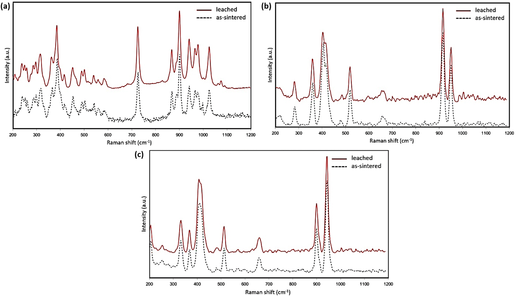 | ||
| Fig. 5 Raman spectra of the α (a), β (b), and γ (c) phase Y2Si2O7 pellets before and post-leaching tests in pH = 3.0 nitric acid for 28 days at 90 °C. | ||
As mentioned earlier, distinct surface morphologies are observed at various grains in the β and γ-phase pellets after leaching. This is exemplified in Fig. 6(a and b), which display two distinct grains along the dashed red lines on the surface of the leached β and γ-phases, respectively. In both Fig. 6(a) and (b), one grain exhibits a non-uniform surface covered with nanostructures, in contrast to the smoother appearance of the other grains. Nevertheless, further analysis is required to determine whether corrosion is occurring along a specific grain orientation.
 | ||
| Fig. 6 (a and b) SEM images showing the post-leaching surface morphology variation of the β and γ-phase Y2Si2O7 pellets respectively. | ||
Fig. 7(a) shows SEM images of the surface microstructure of the amorphous Y2Si2O7 pellet before and after 20 days of the leaching experiment, where no obvious morphological or microstructural changes can be observed. Fig. 7(b–f) display SEM images and EDS maps of the leached pellet cross-section, revealing a surface layer depleted of Y and an enrichment of Si and oxygen, approximately 20–25 μm thick. This is confirmed by the EDS point analysis listed in Table 2, where Y atom% decreases with proximity to the pellet surface. The ratio of Si to oxygen at the surface is approximately 1:2.3, indicating that the corrosion layer is composed of amorphous SiO2 silica. The short-range bonds in amorphous Y2Si2O7 result in a lower density compared to the crystalline samples, creating nanopores that facilitate the penetration of water/H+ ions into the pellet, especially when compared to the crystalline pellets. Y leaches more readily than Si due to its lower Y–O ionic bond strength and activation energy compared to Si–O, which is consistent with observations in rare earth elements (REEs) in titanate and zirconate pyrochlores.26,27 As a result, more Y is leached than Si in the amorphous sample when compared to the crystalline samples, resulting in the exclusive formation of amorphous silica on the surface of the amorphous pellet. These findings will be further supported by the discussion of the measured leaching rates, which will be addressed later.
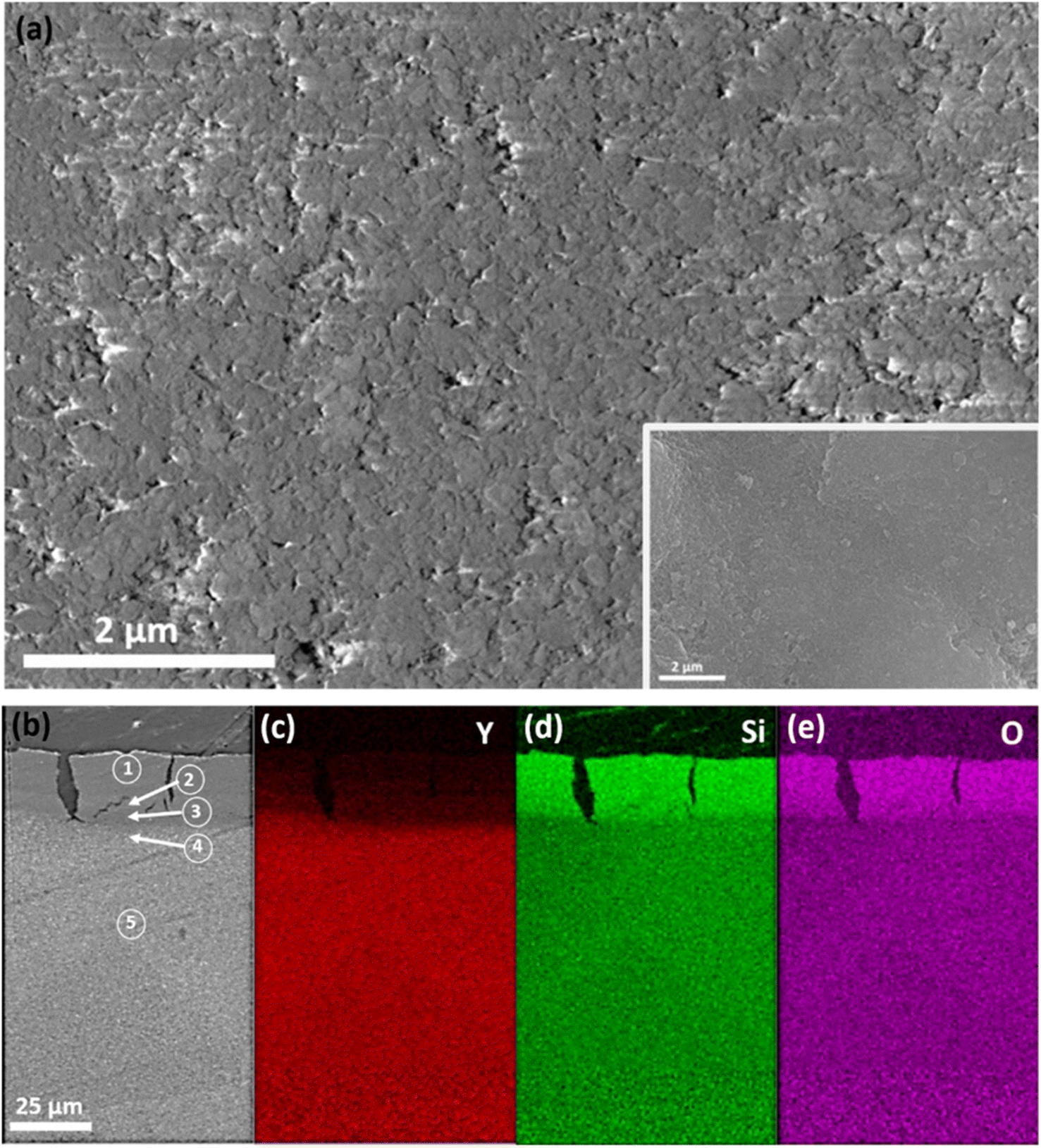 | ||
| Fig. 7 (a) SEM images showing the pristine sintered amorphous Y2Si2O7 pellet and the pellets after the 20 days leaching tests at 90 °C in a solution of nitric acid at pH = 3.0 respectively. (b) A SEM image of the amorphous pellet in a cross-sectional view and the corresponding EDS mappings of the cross-section (c–e). | ||
| EDS atom% | |||||
|---|---|---|---|---|---|
| Region | 1 | 2 | 3 | 4 | 5 |
| Y | 1.32 | 3.65 | 9.04 | 21.79 | 22.97 |
| Si | 29.69 | 26.33 | 21.17 | 13.95 | 14.31 |
| O | 68.99 | 70.02 | 69.80 | 64.25 | 62.72 |
3.2 Elemental release rates and corrosion mechanisms
The measured elemental release in the collected leachate from the semi-dynamic leaching test is presented in Fig. 8. Fig. 8(a and b) display the release rates of Y and Si at 4 hour intervals over the initial 24 hour period of the experiment. Over the course of 24 hours, the release rates for both Y and Si gradually decreased for the α, β, and γ-phases. The release rates of both Y and Si were relatively close for the crystalline phases, with the Y release rates being slightly higher than those of Si. This initial leaching is likely due to the rapid dissolution of material from high energy surface sites such as the grain boundaries and triple junctions, similar observations have been made for the dissolution of other oxide ceramics.31,32 The amorphous sample exhibited expectedly higher release rates than the crystalline phases, and in contrast to the crystalline samples these rates increased slightly over the first 24 hours of the experiment, with the Y release rate being significantly higher than the Si release rate. | ||
| Fig. 8 Leached samples short-term (1 day) release rate of (a) Y and (b) Si. α, β, and γ-phase Y2Si2O7 long-term (28 days) release rates of (c) Y and (d) Si. (e) Amorphous Y2Si2O7 long-term (20 days) release rates of Y and Si; and (f) long-term atomic ratio (Y/Si) of amorphous, α, β and γ-phase Y2Si2O7 samples. | ||
Fig. 8(c and d) display the long-term release rates of Y and Si for the crystalline samples. In contrast to the short-term release rates, the long-term release rates consistently increased with time for all crystalline phases. The α-phase exhibited the highest release rates for both Y and Si, followed by the β-phase, with the γ-phase having the lowest release rates for both elements. This increase in elemental release rates is attributed to the intragranular dissolution of the material, leading to an increase in the surface area exposed to the leachate. The increase in sample surface area caused by the intragranular dissolution of the pellet material is evident from the SEM images of the post-leaching samples shown in Fig. (3). The α-phase, in particular, displayed a sharp increase in both Y and Si release rates between day 2 and day 12, indicating a significant change in the exposed surface area during this period. This may explain why the surface grains of the α-phase are much more corroded compared to the β and γ-phases. Fig. 8(e) presents the long-term release rates of Y and Si for the amorphous sample, where the release rate decreases with time in contrast to the crystalline samples. This reduction in release rate is attributed to the formation of the Si-enriched corrosion layer on the surface of the amorphous sample, as indicated by the EDS map in Fig. 7(a). Fig. 8(f) displays the Y/Si ratio for all four samples over time. The three crystalline phases eventually reach a Y/Si ratio between 1–1.4, while for the amorphous sample, there is a continuous increase in the Y/Si ratio until the end of the experiment. This aligns with the EDS atomic ratio measurements, particularly for the amorphous sample, where a clear decrease in Y from its initial stoichiometric value was observed. There is also good agreement with the EDS results of the crystalline samples in Fig. 4, as the release of Y and Si remains relatively congruent, indicating no enrichment or depletion of either element at the pellet surface.
The α-phase pellet exhibited the highest release rates for both Y and Si at both time scales, indicating its lower chemical durability compared to the other two crystalline phases. Galunin et al. (2011) reported similar findings, with the α-phase showing higher susceptibility to leaching compared to the β and γ-phases in the pH range of 1–5.25 This difference is likely attributable to the α-phase's exposed chain-like crystal structure, in contrast to the 2D layered structure in the β and γ-phases, which makes the α-phase more vulnerable to attacks from water molecules. While the β and γ-phases share a relatively similar structure, the β-phase exhibits higher release rates of both Y and Si compared to the γ-phase, especially over longer periods. This difference may be attributed to the γ-phase having slightly shorter Y–O and Si–O bond lengths, measuring 2.240 Å and 1.608 Å, compared to the bond lengths of 2.265 Å and 1.627 Å in the β-phase, respectively.23,33 Hence the bond strengths of the γ-phase are likely higher than those of the β-phase making it more resistant to dissolution. There is a consistent trend in the short-term release rates of the crystalline samples, characterized by high initial release rates during the first 4 hours of leaching, followed by a gradual reduction in release rates up to 24 hours. In contrast to the short-term release rates, the long-term release rates for the crystalline samples consistently increased over time for all three phases. This increase in long-term release rates is attributed to the increasing surface area of the entire sample, resulting from the intragranular dissolution of the grains at the pellet surface. The change in sample surface area is observed in the SEM images of the post-leaching samples, as shown in Fig. (3). The Y and Si release rates of the amorphous sample were expectedly higher than those of the crystalline phases but decreased over time. Notably, the Y release rate for the amorphous sample was significantly higher than its Si release rate. This phenomenon can be attributed to H+ ions penetrating further into the amorphous matrix, resulting in a faster elemental release over time. In contrast, the crystalline samples, with a much lower grain boundary density, experienced less penetration of H+ ions into the grain boundaries and primarily released Y and Si from their surfaces. Consequently, the release rates of Y and Si from the amorphous sample decreased over time, in contrast to the crystalline samples. This reduction in release rate is a result of the formation of a silica passivation layer on the surface of the amorphous pellet, which is consistent with the high Y/Si ratio observed in the leachate. This protective silica layer contributes to the ongoing decrease in the leaching rates of both Y and Si for the amorphous sample. In contrast, the leaching rates of the crystalline samples continue to increase because this protective layer does not form on their surfaces, and the dissolution of the grains exposes more surface area to the leachate.
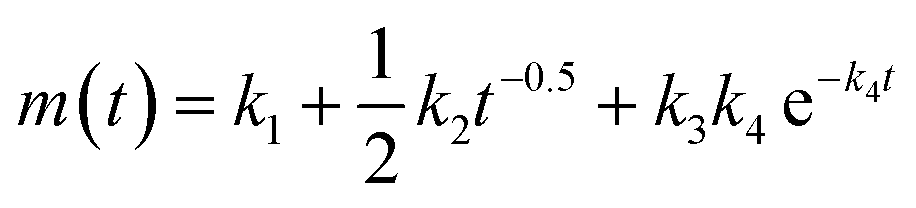
The initial dissolution rates of Y and Si for the 4 samples were estimated by first calculating the accumulated mass species over the 4 hour duration, then fitting the cumulative concentration-time curve linearly. Similarly, the long-term dissolution rates of Y and Si for the crystalline samples were estimated by fitting the cumulative concentration-time curve linearly, due to the constantly increasing release rates, the leaching mechanism can be assumed to be dissolution-controlled. However, the amorphous sample showed continuously decreasing release rates indicating a dominant diffusion-controlled mechanism. The daily release rates of the amorphous sample were fitted to a modified version of Cote's model (k1 + 1/2k2t−0.5), with k1 being determined as the long-term rate by assuming the leaching time (t) is infinite. The estimated initial and long-term rates of all the samples are summarized in Table 3. The short-term release rate of the amorphous sample is higher than its long-term release rate for both Y and Si due to the initial rapid surface dissolution likely from high-energy surface sites, such as grain boundaries and the nanopores at the surface.34 The short-term release rates for Y decrease in the order of amorphous (301.15 mmol m−2 d−1), α (52.40 mmol m−2 d−1), β (40.13 mmol m−2 d−1) and γ-phase (20.84 mmol m−2 d−1). However, the long-term Y release rate for the amorphous sample (51.40 mmol m−2 d−1) is lower than that of the α-phase (54.88 mmol m−2 d−1), while its Si long-term rate (11.80 mmol m−2 d−1) is the lowest of all the samples further indicating a difference in the long-term release mechanism of the amorphous phase versus the crystalline phases which has not been reported until now. Another noticeable difference between the leaching rates of the amorphous and crystalline phases is that the leaching rates of Y and Si are much closer for the crystalline phase compared to those of the amorphous sample. This agrees well with the atomic ratio measurement as the crystalline phases undergo a relatively congruent dissolution with a slight preferential release of yttrium compared to the more incongruent dissolution of the amorphous sample.
| Y | Si | |||||||
|---|---|---|---|---|---|---|---|---|
| Amorphous | α | β | γ | Amorphous | α | β | γ | |
| One-day | ||||||||
| k1 | 301.15 | 52.40 | 40.13 | 20.84 | 80.55 | 49.74 | 32.61 | 16.00 |
| R2 | 0.99 | 0.97 | 0.98 | 0.99 | 0.92 | 0.96 | 0.97 | 0.92 |
| Initial rate (mmol m−2 d−1) | 301.15 | 52.40 | 40.13 | 20.84 | 80.55 | 49.74 | 32.61 | 16.00 |
|
||||||||
| 20/28 days | ||||||||
| k1 | 51.40 | 54.88 | 35.34 | 23.42 | 11.80 | 40.94 | 29.25 | 16.28 |
| k2 | 70.70 | 0 | 0 | 0 | 42.70 | 0 | 0 | 0 |
| k3 | 0 | 0 | 0 | 0 | 0 | 0 | 0 | 0 |
| k4 | 0 | 0 | 0 | 0 | 0 | 0 | 0 | 0 |
| R2 | 0.71 | 0.99 | 1.00 | 1.00 | 1.00 | 1.00 | 1.00 | 1.00 |
| Long-term rate (mmol m−2 d−1) | 51.40 | 54.88 | 35.34 | 23.42 | 11.80 | 40.94 | 29.25 | 16.28 |
4. Conclusions
The semi-dynamic leaching test showed that γ-phase Y2Si2O7 has the lowest leaching rates for both Y and Si, followed by β, α, and the amorphous pellet, suggesting a strong impact of phase composition on the chemical durability of disilicates. The increased leaching of Y and Si in the α-phase is possibly due to its exposed chain-like structure, compared to the 2D layered structure in the γ and β-phases, and thus the α-phase is more susceptible to attacks from water molecules. Microstructural analysis of the post-leaching sample revealed variations in the level of corrosion of the surface grains for the β and γ pellets, indicating a possible grain orientation dependence in the dissolution of the material. The less dense features and exposed nanopores in the amorphous matrix compared to the crystalline pellets resulted in more penetration of H+ ions and thus higher elemental leaching rates. Incongruent leaching was observed for the amorphous phase with a preferential release of Y from the matrix, which led to the formation of a silica-enriched passivation layer at the surface of the pellet. This led to a reduction in the elemental release rates of the amorphous sample over time. While a congruent dissolution of Y and Si was observed for the α, β, and γ-phases.Author contributions
Keith Bryce: data curation & writing – original draft. Kun Yang: data curation. Mingxin Li: data curation. Dong Zhao: data curation. Jie Lian: supervision, conceptualization, methodology, funding acquisition, writing – review & editing.Conflicts of interest
The authors declare that they have no conflict of interest.Acknowledgements
This work was supported as part of the Center for Performance and Design of Nuclear Waste Forms and Containers (WastePD), an Energy Frontier Research Center (EFRC) funded by the U.S. Department of Energy, Office of Science, Basic Energy Sciences under Award DE-SC0016584.References
- C. L. Thorpe, J. J. Neeway, C. I. Pearce, R. J. Hand, A. J. Fisher, S. A. Walling, N. C. Hyatt, A. A. Kruger, M. Schweiger and D. S. Kosson and others, Forty years of durability assessment of nuclear waste glass by standard methods, npj Mater. Degrad., 2021, 5, 61 CrossRef
.
- J. Heinonen and F. Gera, Nuclear Waste Disposal: Understanding What Happens Underground, Aalam Al-Zarra, Syria, 1986, vol. 2 Search PubMed
- D. W. Readey and C. R. Cooley, Ceramic and Glass Radioactive Waste Forms, 1977 Search PubMed
- J. M. Farmer, L. A. Boatner, B. C. Chakoumakos, M.-H. Du, M. J. Lance, C. J. Rawn and J. C. Bryan, Structural and crystal chemical properties of rare-earth titanate pyrochlores, J. Alloys Compd., 2014, 605, 63–70 CrossRef CAS
- S. V. Yudintsev, S. V. Stefanovsky and B. S. Nikonov, A pyrochlore-based matrix for isolation of the REE-actinide fraction of wastes from spent nuclear fuel reprocessing, Dokl. Earth Sci., 2014, 454(1), 54 CrossRef CAS
- K. Yang, W. Zhu, S. Scott, Y. Wang, J. Wang, B. J. Riley, J. Vienna and J. Lian, Immobilization of cesium and iodine into Cs3Bi2I9 perovskite-silica composites and core–shell waste forms with high waste loadings and chemical durability, J. Hazard. Mater., 2021, 401, 123279 CrossRef CAS PubMed
- K. Bryce, K. Yang, Y. Wang and J. Lian, Chemical durability and degradation mechanisms of CsPbI 3 as a potential host phase for cesium and iodine sequestration, RSC Adv., 2022, 12(20), 12242–12252 RSC
- E. R. Vance, P. J. Angel, B. D. Begg and R. A. Day, Zirconolite-rich titanate ceramics for high-level actinide wastes, MRS Online Proc. Libr., 1993, 333 Search PubMed
- D. M. Strachan, R. D. Scheele, E. C. Buck, A. E. Kozelisky, R. L. Sell, R. J. Elovich and W. C. Buchmiller, Radiation damage effects in candidate titanates for Pu disposition: Zirconolite, J. Nucl. Mater., 2008, 372(1), 16–31 CrossRef CAS
- K. Bryce, K. Yang, T. Yao and J. Lian, Chemical Durability of Multicomponent Lanthanide Zirconate Solid Solutions, Ceram. Int., 2023, 49(23), 39196–39204 CrossRef CAS
- A. E. Ringwood, S. E. Kesson, N. G. Ware, W. Hibberson and A. Major, Immobilisation of high level nuclear reactor wastes in SYNROC, Nature, 1979, 278, 219–223 CrossRef CAS
- E. Galunin, M. D. Alba and M. Vidal, Stability of Rare-Earth Disilicates: Ionic Radius Effect, J. Am. Ceram. Soc., 2011, 94(5), 1568–1574 CrossRef CAS
- M. D. Alba, P. Chain and M. M. Orta, Chemical reactivity of argillaceous material in engineered barrier: Rare earth disilicate formation under subcritical conditions, Appl. Clay Sci., 2009, 43(3–4), 369–375 CrossRef CAS
- M. Alba, A. Becerro, M. Castro and A. Perdigón, Hydrothermal reactivity of Lu-saturated smectites: Part I. A long-range order study, Am. Mineral., 2001, 86(1–2), 115–123 CrossRef CAS
- L. Pidol, A. Kahn-Harari, B. Viana, B. Ferrand, P. Dorenbos, J. T. M. De Haas, C. W. E. Van Eijk and E. Virey, Scintillation properties of Lu2Si2O7: Ce3+, a fast and efficient scintillator crystal, J. Phys.: Condens. Matter, 2003, 15(12), 2091 CrossRef CAS
- T. Horiai, S. Kurosawa, R. Murakami, J. Pejchal, A. Yamaji, Y. Shoji, V. I. Chani, Y. Ohashi, K. Kamada, Y. Yokota and A. Yoshikawa, Crystal growth and luminescence properties of Yb2Si2O7 infra-red emission scintillator, Opt. Mater., 2016, 58, 14–17 CrossRef CAS
- L. R. Turcer, A. R. Krause, H. F. Garces, L. Zhang and N. P. Padture, Environmental-barrier coating ceramics for resistance against attack by molten calcia-magnesia-aluminosilicate (CMAS) glass: Part I, YAlO3 and γ-Y2Si2O7, J. Eur. Ceram. Soc., 2018, 38(11), 3905–3913 CrossRef CAS
- L. R. Turcer, A. R. Krause, H. F. Garces, L. Zhang and N. P. Padture, Environmental-barrier coating ceramics for resistance against attack by molten calcia–magnesia–aluminosilicate (CMAS) glass: Part II, β-Yb2Si2O7 and β-Sc2Si2O7, J. Eur. Ceram. Soc., 2018, 38(11), 3914–3924 CrossRef CAS
- V. L. Wiesner, D. Scales, N. S. Johnson, B. J. Harder, A. Garg and N. P. Bansal, Calcium–magnesium aluminosilicate (CMAS) interactions with ytterbium silicate environmental barrier coating material at elevated temperatures, Ceram. Int., 2020, 46(10), 16733–16742 CrossRef CAS
- J. Felsche, Polymorphism and crystal data of the rare-earth disilicates of type RE2Si2O7, J. Less-Common Met., 1970, 21(1), 1–14 CrossRef CAS
- J. Ito and H. Johnson, Synthesis and study of yttrialite, American Mineralogist: Journal of Earth and Planetary Materials, 1968, 53(11–12), 1940–1952 CAS
- V. Kahlenberg, W. Wertl, D. M. Többens, R. Kaindl, P. Schuster and H. Schottenberge, Rietveld Analysis and Raman Spectroscopic Investigations on α-Y2Si2O7, Z. Anorg. Allg. Chem., 2008, 634(6–7), 1166–1172 CrossRef CAS
- G. u. J. Redhammer and G. Roth, β-Y2Si2O7, a new thortveitite-type compound, determined at 100 and 280 K, Acta Crystallogr., Sect. C: Cryst. Struct. Commun., 2003, 59(10), i103–i106 CrossRef PubMed
- A. I. Becerro and A. Escudero, Revision of the crystallographic data of polymorphic Y2Si2O7 and Y2SiO5 compounds, Phase Transitions, 2004, 77(12), 1093–1102 CrossRef CAS
- E. Galunin, M. Vidal and M. D. Alba, The effect of polymorphic structure on the structural and chemical stability of yttrium disilicates, Am. Mineral., 2011, 96(10), 1512–1520 CrossRef CAS
- K. Yang, P. Lei, T. Yao, B. Gong, Y. Wang, M. Li, J. Wang and J. Lian, A systematic study of lanthanide titanates (A2Ti2O7) chemical durability: corrosion mechanisms and control parameters, Corros. Sci., 2021, 185, 109394 CrossRef CAS
- K. Yang, Y. Wang, P. Lei, T. Yao, D. Zhao and J. Lian, Chemical durability and surface alteration of lanthanide zirconates (A2Zr2O7: A= La–Yb), J. Eur. Ceram. Soc., 2021, 41(12), 6018–6028 CrossRef CAS
- ASTM-C1308-08, Accelerated Leach Test for Diffusive Releases from Solidified Waste and a Computer Program to Model Diffusive, Fractional Leaching From Cylindrical Waste Forms, ASTM International, West Conshohocken, PA, 2009 Search PubMed
- P. L. Cote, T. W. Constable and A. Moreira, An evaluation of cement-based waste forms using the results of approximately two years of dynamic leaching, Nucl. Chem. Waste Manage., 1987, 7(2), 129–139 CrossRef CAS
- J. Parmentier, P. R. Bodart, L. Audoin, G. Massouras, D. P. Thompson, R. K. Harris, P. Goursat and J.-L. Besson, Phase transformations in gel-derived and mixed-powder-derived yttrium disilicate, Y2Si2O7, by X-ray diffraction and 29Si MAS NMR, J. Solid State Chem., 2000, 149(1), 16–20 CrossRef CAS
- S. Szenknect, S. Finkeldei, F. Brandt, J. Ravaux, M. Odorico, R. Podor, J. Lautru, N. Dacheux and D. Bosbach, Monitoring the microstructural evolution of Nd2Zr2O7 pyrochlore during dissolution at 90 C in 4 M HCl: implications regarding the evaluation of the chemical durability, J. Nucl. Mater., 2017, 496, 97–108 CrossRef CAS
- C. L. Corkhill, E. Myllykylä, D. J. Bailey, S. M. Thornber, J. Qi, P. Maldonado, M. C. Stennett, A. Hamilton and N. C. Hyatt, Contribution of Energetically Reactive Surface Features to the Dissolution of CeO2 and ThO2 Analogues for Spent Nuclear Fuel Microstructures, ACS Appl. Mater. Interfaces, 2014, 6, 12279–12289 CrossRef CAS PubMed
- Y. Luo, J. Wang, J. Wang, J. Li and Z. Hu, Theoretical predictions on elastic stiffness and intrinsic thermal conductivities of yttrium silicates, J. Am. Ceram. Soc., 2014, 97(3), 945–951 CrossRef CAS
- A. Lüttge, R. S. Arvidson and C. Fischer, A stochastic treatment of crystal dissolution kinetics, Elements, 2013, 9(3), 183–188 CrossRef
| This journal is © The Royal Society of Chemistry 2024 |