 Open Access Article
A review on MOFs synthesis and effect of their structural characteristics for hydrogen adsorption
John Letwabaa,
Uwa Orji Uyor *ab,
Mapula Lucey Mavhungua,
Nwoke Oji Achukac and
Patricia Abimbola Popoolaa
aDepartment of Chemical, Metallurgical & Materials Engineering, Tshwane University of Technology, P.M.B X680, Pretoria, 0001, South Africa. E-mail: uwa.uyor@unn.edu.ng
bDepartment of Metallurgical and Materials Engineering, University of Nigeria, Nsukka, Private Bag 0004, Nsukka, Enugu State, Nigeria
cDepartment of Agricultural and Bioresources Engineering, University of Nigeria, Nsukka, Private Bag 0004, Nsukka, Enugu State, Nigeria
First published on 30th April 2024
Abstract
Climate change is causing a rise in the need to transition from fossil fuels to renewable and clean energy such as hydrogen as a sustainable energy source. The issue with hydrogen's practical storage, however, prevents it from being widely used as an energy source. Current solutions, such as liquefied and compressed hydrogen storage, are insufficient to meet the U.S. Department of Energy's (US DOE) extensive on-board application requirements. Thus, a backup strategy involving material-based storage is required. Metal organic frameworks (MOFs) belong to the category of crystalline porous materials that have seen rapid interest in the field of energy storage due to their large surface area, high pore volume, and modifiable structure. Therefore, advanced technologies employed in the construction of MOFs, such as solvothermal, mechanochemical, microwave assisted, and sonochemical methods are reviewed. Finally, this review discussed the selected factors and structural characteristics of MOFs, which affect the hydrogen capacity.
1. Introduction
The world is migrating away from utilizing fossil fuels such as coal as the main source of energy. This is ascribed to decreasing fossil fuel supply and the negative impact on the environment caused by the emission of toxic gases such as carbon dioxide. In 2022, South Africa emitted 435 million metric tons of carbon dioxide from fossil fuel combustion of which the transport sector accounted for 23%.1 Moving away from fossil fuels and toward alternate sources of energy is thus one strategy to reduce the growth of CO2 emissions. One of the most intriguing potential replacements for carbon-based energy sources is hydrogen. The attractiveness of using hydrogen as an energy source is mainly due to its intrinsic characteristics, viz, higher energy density than gasoline, environmental compatibility, huge energy efficiency, and non-toxicity.2 Among its satisfaction, hydrogen has a high energy density by weight, having a value of 142 MJ kg−1, which is about three times more energy than gasoline and seven times more than coal per unit mass.3 However, several technical drawbacks remain to be solved before significantly introducing hydrogen as an energy source into the energy system.4 This includes the cost-effective storage of hydrogen in a safely and economically as a primary problem.2 Hence, there has been a need to intensify research work on alternative hydrogen storage technology to address the said technical issues.Metal organic frameworks (MOF) are promising materials for hydrogen storage technology. They are microporous crystalline structures made up of metal ions connected by organic ligands which produce micropores (<2 nm) and pathways.5 Their unique characteristics namely thermal stability, rigidity, structural flexibility, high void volume, high surface area, adjustable pore size, and tailorable cavities of uniform size made MOFs receive a lot of attention in the research and development for hydrogen storage,6–8 organic pollutant removal,9 rechargeable batteries10,11 sensors application12 and photocatalyst for removal of antibiotics and CO2 photoreduction due to their high active sites and catalytic activity.13 The most common organic linkers like dicarboxylates (malonic acid, succinic acid, oxalic acid, glutaric acid, terephthalic acid), azoles (pyrrodiazole, 1,2,3-triazole) and tricarboxylates (trimesic acid, citric acid) are commonly used in the synthesis of MOFs.2 MOF-5 (Zn4O (BDC)3 where BDC denotes 1,4-benzenedi-carboxylate) is a promising material for hydrogen storage at both cryogenic and ambient conditions. The reported hydrogen adsorption storage capacity at cryogenic conditions and 1 bar is 4.5 wt%, whereas at ambient conditions and 1 bar is 1 wt%.14,15 Furukawa et al.16 prepared MOF-200 (Zn4O(CO2))6 [4,4,4-(benzene-1,3,5-triyl-tris(benzene-4,1-diyl))tribenzoate] and MOF-210 (Zn4O(CO2))6[4,4,4-(benzene-1,3,5-triyl-tris(ethyne-2,1-diyl))tribenzoate]/biphenyl-4,4-dicarboxylate from the solvothermal reaction of organic linkers and zinc nitrate. The hydrogen consumption obtained at 77 K and 80 bar for both MOF-200 and MOF-210 was 15 wt% and 14 wt% respectively. The excess uptake at ambient conditions at 80 bar for MOF-210 was 0.53 wt%. The authors believe that the lower hydrogen uptake was due to the larger average pore diameter recommended by DOE (0.7–1.2 nm to maximize the room temperature hydrogen uptake capacity).
A different intriguing family of MOFs is created by synthesizing copper with carboxylic acids. These MOFs are composed of a paddle wheel-style [Cu2(OOC)4] SBU and a carboxylate linker. Chui et al.17 synthesized MOF which consists of Cu(II) paddlewheel SBU and BTC, with a Langmuir surface area of 917.6 m2 g−1. In general, this kind of MOFs in addition to open metal locations offer large specific surface area and have strong interactions with gas molecules, leading to a higher amount of hydrogen gas being adsorbed. Azolate based MOFs are a class of compounds having high chemical and thermal stability. Their hydrogen storage capacity has been documented.18–20 The highest hydrogen adsorption capacity of one of ZIFs namely Zn(MeIM)2(ZIF-8) reported to date is 3.3 wt% of hydrogen at 77 K and 30 bar.21 This implies that carboxylate-based MOFs are better than ZIFs-based material for the storage of hydrogen. To improve hydrogen storage at ambient conditions, Frost et al.22 carried out calculations to forecast the hydrogen adsorption isotherms of the isoreticular metal organic framework. The findings showed that primarily due to the low adsorption energy between MOF and hydrogen, the connections that already have established for absolute hydrogen adsorption at 77 K are not valid for absolute hydrogen adsorption at 298 K. Also, they found that for large loadings, the excess adsorption of hydrogen at 298 K corresponds better with surface area than with free volume. At fewer loadings, the excess adsorption of hydrogen at 298 K relates well with the heat of adsorption. It was recommended that the MOFs should offer an isosteric heat of 15 kJ mol−1 or greater yet maintain a free volume of 2.5 cm3 g−1 and an empty percentage of 85% to achieve the aim of 9 wt% and 30 g L−1.
In a different investigation, Pt nanomaterials and carbon black were used to synthesize MOF-5, Zn4O (1,4-benzenedicarboxylate)3 by Kim and colleagues.23 At 298 K and 100 pressure, the composite of carbon black/Pt/MOF-5 adsorbs 0.62 wt% of hydrogen, which is an improvement over MOF-5 (0.44 wt%). It was found that it is challenging for the hydrogen to be kept on the surface of the MOFs if the value of the adsorption enthalpy is smaller, particularly in ambient settings. To enhance the diffusion of dissociated hydrogen to the surface of the adsorbent the loading of a metal catalyst, Pt (1, 4, 7, and 10%) was varied and it was found that 4% is the optimum loading with 0.88 wt% of hydrogen storage capacity. Furthermore, to protect the material from moisture, carbon black was introduced in the optimized formulation. This resulted in the reduction of hydrogen storage capacity from 0.88 wt% to 0.62 wt%. The authors stated that this was attributed to the reduction of surface area and blockage of the pores by carbon black. In this review, we discussed various technologies employed in the construction of MOFs, such as solvothermal, mechanochemical, microwave assisted, and sonochemical methods. Finally, we discuss the selected factors or structural characteristics of MOFs, which affect the hydrogen capacity. This review will form a basis for advanced research and development of novel MOFs for hydrogen energy storage in the promotion of clean and sustainable energy.
2. Overview of hydrogen energy target
The U.S. Department of Energy (US DOE) has announced a technical focus to provide the end goals during the research and development of H2 storage technologies.24 Fig. 1 points out certain important technical data, which incorporates targeted degrees of storage capability and costs, data derived from Energy.24 As per the guideline of the U.S. DOE by 2025, emerging research and development work on H2 storage technology specifically on light-duty vehicles should achieve the gravimetric and volumetric storage capabilities of 5.5 wt% and 40 g L−1 respectively at ambient working circumstances.24–26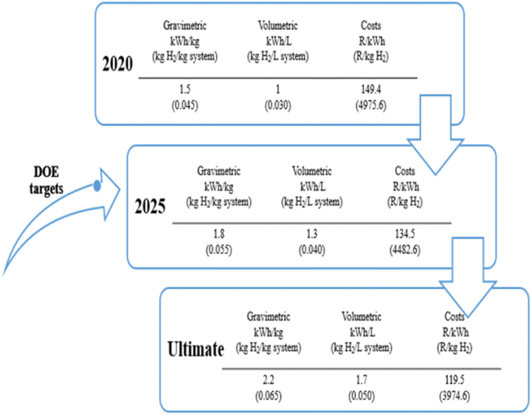 | ||
| Fig. 1 Targeted objectives for hydrogen storage technologies set by the US DOE. Data derived from Energy24 with permission from DOE, copyright 2017. | ||
As of now, there are no technologies, which complement the DOE hydrogen storage targets. According to several researchers, the best hydrogen storage qualities should be attained to use hydrogen satisfactorily. These qualities include large gravimetric and volume densities, minimal sorption temperatures and heat exchange, excellent reversibility, lightweight, quick reaction kinetics, cycle stability, and reduced costs.27–30 Currently, there is no technology, which is compatible to meet the desired optimum characteristic of hydrogen storage at ambient conditions. Therefore, research and development of solid materials for hydrogen storage are required to fulfil the key role of achieving the set target.
Several methods have been developed for hydrogen storage as illustrated in Fig. 2, which include compression in gas cylinders, liquefaction in cryogenic tanks, storage in metal hydride alloys, physisorption, and chemisorption.31–33 Among these, compression is the most employed technology for hydrogen storage although high pressure has to be used to increase hydrogen density, which results in higher operational costs.2 Liquid hydrogen storage involves a liquefaction process in which the operation temperature is extremely low (−250 °C) which poses a major challenge to be achieved.34 Additionally, up to 40% of energy content can be lost in the process.35 The major setback for physical-based storage (compressed and liquefied) is the failure to achieve the DOE targets24 from energy density and cost perspectives.31
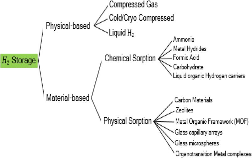 | ||
| Fig. 2 Hydrogen storage methods. Reproduced from Moradi and Groth34 with permission from Elsevier, copyright 2019. | ||
Both chemisorption and physisorption are material-based hydrogen storage. In chemical adsorption, hydrogen is chemically bonded to the storage material. There are groups of materials that can be used for chemical sorption such as metal hydrides, ammonia, formic acid, carbohydrates, and many more. Among these groups of materials, metal hydrides are the most attractive candidates due to their ability to achieve relatively high volumetric density.30,36–38 However, the gravimetric capacity does not meet the set target by DOE.24 Moreover, metal hydride suffers from poor kinetics opting for charging time longer than the DOE target,24 and requires high temperature for adsorption/desorption. Adsorption in which gas molecules adhere to the surface of a solid due to weak intermolecular forces of attraction without the creation of a chemical bond between the adsorbate and the adsorbent is known as physical adsorption. For the accumulation of hydrogen, a variety of adsorbates have been created, including carbon-based materials, zeolites, organotransition metal complexes, glass capillary arrays, porous silicas, and metal organic frameworks.39
Physical adsorption on porous materials has the potential to store hydrogen due to their unique characteristics such as fast kinetics at low ambient conditions, large surface area, reversibility of the storage process, and lightweight.40–42 Covalent-organic frameworks (COFs), zeolites, and porous aromatic MOFs are some of the adsorbent materials that have been evaluated for hydrogen storage systems. Ramirez-Vidal et al.43 synthesized one of the COFs namely hyper-crosslinked polymers (HCPs) by utilizing the Friedel–Crafts reaction using carbazole, anthracene, dibenzothiophene, and benzene as raw materials and dimethoxymethane as a crosslinker.43 Physical properties of the synthesized HCPs obtained are a pore volume of 0.87 cm3 g−1 and specific surface area of 1137 m2 g−1. The optimal hydrogen capacity acquired was 2.1 wt% at operating temperature and pressure of 77 K and 40 bar respectively which is below the DOE target.24 Additionally, COFs-based materials suffer from high costs of precursors, poor mechanical properties, and complex synthesis processes.2 Carbon-based materials have been studied as potential hydrogen storage materials due to reduced costs, reduced weights, large surface area, large pore structure, and chemical stability.44–48 Thermally exfoliated graphene oxide with high surface area and pore volume was found to be an attractive material for hydrogen storage due to promising hydrogen uptake. Additionally, the high hydrogen uptakes on exfoliated GO is associated with the distance between the graphene layers, which promotes hydrogen diffusion. In recent work, Singh and De49 used the thermal exfoliation process under various circumstances to synthesize exfoliated graphite oxide. For air-exfoliated EGO with a specific surface area of 286 m2 g−1, mean pore size of 2.9 nm, and total pore volumes of 1.2 cm3 g, the optimal hydrogen absorption was 3.34 wt% at 77 K and 30 bar.
3. Structure and properties of MOFs
MOFs have become an essential material for consideration in hydrogen storage applications. These categories of functional materials are primarily created by the interaction of organic molecules connecting to form crystallinity and porous structure with singular metal cations (primary building units [PBU]) or metal agglomerations [secondary building units [SBUs]]. Several metal clusters and modified organic linkers have been used in the synthesis of MOFs to create these materials under various process circumstances, yielding an exceptional level of structural variety.50 The ornamentation of SBU affects MOFs characteristics such as structural directionality and geometric requirements.The structural features of MOFs include size, porosity, and morphology. Their several factors that affect the structural characteristics of MOFs such as nucleation, additive and synthesis on (size); template, ligand, and additive on (porosity); metal ion, spacer, ligand, capping ligand, hydrotrope, synthesis, and additive on (morphology).51 Recently, Suresh and co-workers52 assessed the effect of an additive consisting of a m-terephenyl-4,4-dicarboxylic acid moiety on the emergence of MOF-5 morphologies (Fig. 3). Fig. 3a shows cubic morphology crystals with {100} crystallographic facets which suggest slow crystal growth. Cuboctahedral-shaped crystals covered by six {100} and eight {111} facets are displayed (Fig. 3b). Octahedral crystal morphology growth along the {111} facet direction and {100} facet. These morphology evolutions demonstrated the effect of additives on interaction with crystallographic facets about the crystal growth rate. Li et al.53 constructed two novel porous MOFs, namely, [Zn4(μ3-OH)2(TPO)2(H2O)2 (product 1)] and [Zn6(μ6-O)(TPO)2](NO3)4·3H2O (product 2)] based on H3TPO ligands via solvothermal methods. These MOFs consist of butterfly-shaped Zn4(μ3-OH)2(CO2)6 and octahedral Zn6(μ6-O)(CO2)6 SBU, which resulted in obtaining a three-dimensional microporous framework with flu and pyr topologies, large cavities and one dimensional channels (see Fig. 4 and 5).53 Generally, the high structural stability of MOFs is associated with SBU as they serve as rigid vertices propagated into a framework by strongly bonding with organic struts. According to Butova et al.54 the choice and deletion of a linker could change the symmetry structure. Whenever a different linker is used, the structure's symmetry is preserved. But as the carbon chain lengthens, the characteristics of the unit cell alter. Moreover, symmetry changes as a result of changes in the mutual arrangement of functionalities.
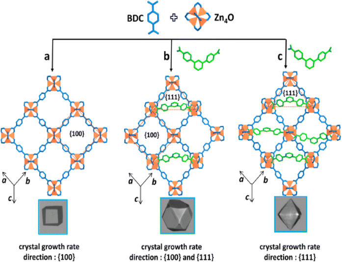 | ||
| Fig. 3 Cubic crystal shape (a) is governed by the slower rate of crystal growth in the direction of faces. Additive (m-terephenyl-4,4-dicarboxylate indicated in green) blocking MOF-5 growth along the {111} direction partially or completely at the expense of all {100} facets during crystal growth in creation of cuboctahedral (b) and octahedral (c) crystal morphologies. Reproduced from Suresh et al.52 with permission from American Chemical Society, copyright 2021. | ||
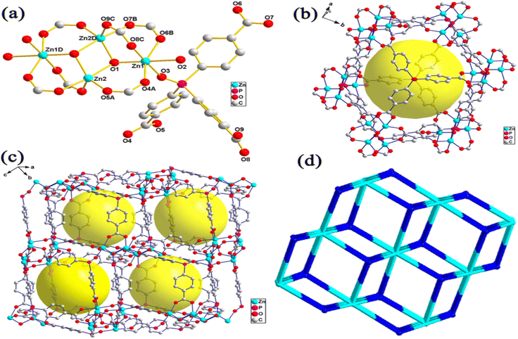 | ||
| Fig. 4 (a) Coordination environment for zinc(II) atoms in complex system, (b) cagelike cavity supported by Zn4 cluster and TPO3+ Ligands, (c) packing structure of cagelike cavity, and (d) flu net topology. Reproduced from Li et al.53 with permission from American Chemical Society, copyright 2014. | ||
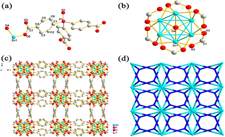 | ||
| Fig. 5 (a) Asymmetric unit of complex system 2, (b) SBU in complex 2, (c) 3D packing stricture of complex system 2 demonstrating the open micropores, and (d) Pry net topography of complex system 2. Reproduced from Li et al.53 with permission from American Chemical Society, copyright 2014. | ||
Great porosity, great surface area, less density, hardness, bulk modulus, shear modulus, and Young's modulus may be necessary for MOFs utilized in gas adsorption, gas sensing, and gas storage applications.55–57 Suh et al.21 disclosed the BET surface area of MOF-200, MOF-210, and MOF-205 as 4530, 6240, and 4460 m2 g−1, respectively. In terms of crystal density, MOF-200, and MOF-210 recorded the lowest value of 0.25 g cm−3 among MOFs, MOF-205 with a crystal density of 0.38 g cm−3. Mechanical properties are vital properties of MOFs, which among others are affected by the removal of quest molecules and porosity.58 It is reported that a large degree of coordination of the metal center to the organic linkers positively influences the mechanical stability of MOFs.59 Burtch et al.60 improved the young modulus of Zn2(L)2(DABCO) from 2.08 to 6.53 GPa by using N,N-dimethylformamide (DMF) and toluene as a solvent. This improvement was attributed to a change in the geometry of the framework during synthesis.
4. Densities of compacted MOFs
The performance of MOFs in these applications is intricately linked to their density. In applications concerning H2 absorption and desorption, the volumetric capacity of MOFs plays a pivotal role. This capacity, in turn, hinges on the packing efficiency of MOFs, which is significantly influenced by their density. Notably, denser MOFs can be pelletized to enhance both their processability and volumetric capacity. When considering hydrogen storage applications, MOF density assumes paramount importance in achieving high storage capacities. MOFs characterized by high apparent densities tend to exhibit greater hydrogen storage capabilities due to their expansive surface area and porosity. However, it's worth noting that denser MOFs may also exhibit reduced porosity, potentially impacting their hydrogen storage capacity.61Also, various techniques and methods such as crystallographic density, helium pycnometry, gas adsorption, and Archimedes' principle are employed to measure the density of metal–organic frameworks (MOFs), each offering its unique advantages and limitations. For instance, crystallographic density derives the MOF's density from its crystal structure, assuming a pristine, defect-free crystal. Often used as a reference, this method is straightforward and omits the need for experimental measurements. However, it overlooks defects and impurities, which can substantially influence MOF density. In contrast, helium pycnometry gauges the skeletal density of MOFs by measuring the volume of displaced helium gas, convertible to the MOF's apparent density. This technique excels in accuracy and reliability, even when defects or impurities are present. Nevertheless, it necessitates specialized equipment and can be time-intensive.62 Gas adsorption takes a different route, focusing on MOF surface area and porosity by adsorbing gas molecules onto the MOF surface. MOF density calculations stem from these surface area and pore volume measurements, critical parameters for many applications. However, this method presumes homogeneity and uniform pore size distribution within the MOF, which may not hold for all MOFs. Meanwhile, Archimedes' principle approaches density measurement by comparing the weight of the MOF in air and a liquid of known density. From this weight difference and the MOF's volume, its density can be determined. Simplicity is its strength, as it requires no specialized equipment. Nonetheless, it can be influenced by factors like air bubbles or surface roughness, potentially impacting measurement accuracy.
It has been shown that the assessment of MOF density relies on a range of techniques, each carrying its own set of benefits and limitations. Helium pycnometry stands out for its reliability and precision, while gas adsorption supplies valuable insights into MOF surface characteristics. Crystallographic density offers a straightforward reference point, albeit without considering defects. Archimedes' principle provides simplicity but can be sensitive to certain environmental factors. Researchers judiciously select these methods based on their research goals and the specific attributes of the MOFs under investigation, ensuring a comprehensive understanding of MOF density and its ramifications in diverse applications. It has been shown that the density of metal–organic frameworks (MOFs) is influenced by several factors, including chemical composition, crystal structure, pore size and framework topology, temperature and pressure conditions, and guest molecules and adsorption.63
The chemical composition of MOFs can affect their density due to differences in atomic mass and packing efficiency. For example, MOFs with heavier metal ions or larger organic ligands tend to have lower densities due to their larger atomic radii and lower packing efficiency. On the other hand, MOFs with lighter metal ions or smaller organic ligands tend to have higher densities due to their smaller atomic radii and higher packing efficiency. For example, MOF-74 is a series of MOFs with different metal ions (e.g., Mg, Co, Ni) and organic ligands (e.g., benzene-1,3,5-tricarboxylate) that have different densities. The density of MOF-74 increases with increasing atomic mass of the metal ion, with Ni-MOF-74 having the highest density.64 The crystal structure of MOFs can affect their density due to differences in packing efficiency and void space. MOFs with higher symmetry and more compact crystal structures tend to have higher densities, while MOFs with lower symmetry and more open crystal structures tend to have lower densities. For example, MOFs with diamondoid or zeolitic imidazolate frameworks (ZIFs) tend to have higher densities due to their compact crystal structures.
Likewise, the pore size and framework topology of MOFs can affect their density due to differences in void space and packing efficiency. MOFs with larger pore sizes and more open framework topologies tend to have lower densities, while MOFs with smaller pore sizes and more compact framework topologies tend to have higher densities. For example, MOFs with isoreticular frameworks (IRFs) tend to have higher densities due to their compact framework topologies.65 Also, Halford was able to demonstrate that using an actinide building block, a material that is unusual, and complex, to create the lowest density of MOFs. He points out that actinides, which are heavy elements near the bottom of the periodic table, are not often thought of as low-density materials. In the research, he prescribed that if the MOF's structure was highly porous and empty, the size of the metal wouldn't matter. Due to this research, it has been recorded in comparison with other known MOF that to date, the complex NU-1301 MOF composed of uranium oxide and tricarboxylate organic linker units has the lowest density66 with 0.124 g cm−3 despite its high surface area and high pore volume. Fig. 6 presents the physical structure of the NU-1301. It is deduced that the NU-1301-unit cell is made up of five cage structures (shown in green and other colours) that are combined to form the cuboctahedron building block (top left), which is composed of uranium oxide nodes and tricarboxylate bridging ligands.
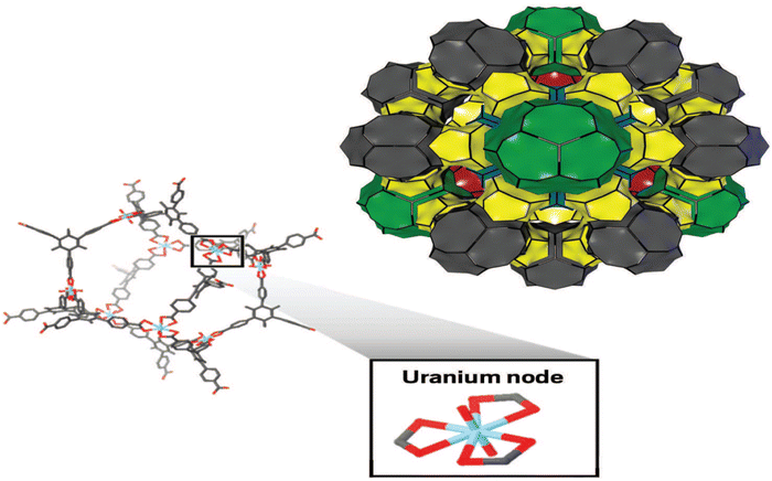 | ||
| Fig. 6 Simple to complex NU-1301 MOF reproduced from Halford66 with permission from American Chemical Society, copyright 2017. | ||
The temperature and pressure conditions during MOF synthesis and characterization can affect their density due to changes in crystal structure and guest molecule adsorption. For example, MOFs synthesized at higher temperatures or pressures tend to have higher densities due to increased packing efficiency and decreased void space. However, guest molecules adsorbed in the MOF pores can also affect the density by increasing the overall volume of the MOF. For instance, HKUST-1 is an MOF that undergoes a reversible phase transition at high pressure, resulting in a change in crystal structure and density. At low pressure, HKUST-1 has a lower density due to the presence of guest molecules in the pores, while at high pressure, the guest molecules are expelled, and the density increases. The guest molecules adsorbed in the MOF pores can affect the density by increasing the overall volume of the MOF. For example, MOFs with high guest molecule adsorption tend to have lower densities due to increased void space.
To address these issues, scientists have created a number of densification processes that allow MOFs to be made denser while yet maintaining their internal pore structure. Compaction, pelletization, hot pressing, and solvent-assisted grinding are a few of these methods. Numerous research have shown that it is feasible to improve the mechanical stability and gas adsorption capability of MOFs by adjusting their compact density. For instance, Purewal et al.67 observed that compared to the powder, the volumetric H2 absorption of compacted MOF-5 with a density of 0.51 g cm−3 dramatically increased. MIL-101 compacted at 8 MPa with a density varying between 0.45 and 0.47 g cm−3 was described by Ardelean et al.68 On the other hand, densified Zr-MOFs and HKUST-1 MOFs have a larger volumetric nitrogen adsorption capability than their powder counterparts, according to Dhainaut et al.69 The investigations have demonstrated that densification procedures can influence the surface area, pore volume, and pore size distribution of MOFs. The mechanical stability of MOFs may also be impacted by the densification process. To guarantee that MOFs' storage capacity is not diminished, it is crucial to strike a balance between densification and preserving their natural textural qualities.
5. Design and synthesis strategies of MOFs for hydrogen storage
There are different methods used to synthesize MOFs among them are traditional synthesis (solvothermal), electrochemical, microwave, sonochemical, and mechanochemical as summarized in Fig. 7. When creating MOFs, synthetic circumstances and the type of organic linkers must be taken into account because they have a significant impact on the coordination of the metal centers, overall structure, and characteristics of MOFs.70 Therefore, optimization in the design and synthesis to attain MOFs of high performance is crucial. This section discusses various synthetic strategies used for MOFs.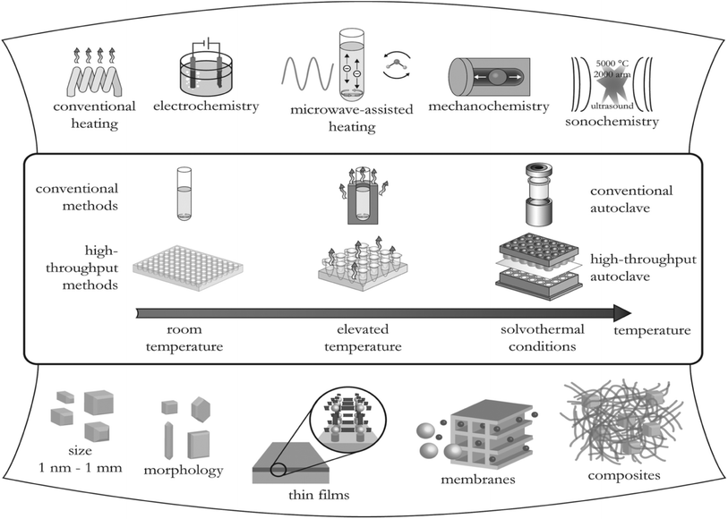 | ||
| Fig. 7 Various methods of synthesizing MOFs and their possible final reaction products. Reproduced from Stock and Biswas71 with permission from American Chemical Society, copyright 2012. | ||
5.1 Solvothermal/hydrothermal synthesis
The conventional method employed to construct MOFs is solvothermal or hydrothermal synthesis. In the solvothermal method, any solvent is used, either polar or non-polar solvent whereas, the hydrothermal method uses water as the solvent. Since the precursors, metal salts, and organic linkers are highly soluble in these organic solvents, they are frequently used in the building of MOFs. Examples include N,N-dimethylformamide (DMF), N,N-dimethylacetamide (DMA), and ethanol. Banerjee and Parise72 stated that the setback in hydrothermal reactions is the fact that they are considered unstable for the synthesis of large dimensional network structures because of the great hydration energy of the metal centers. The solvothermal method affords high yield and better development of single crystals, which are important for the structural network. Structure-directing agents (metal salts and organic linkers) promote the growth of these crystals. Synthesis parameters that influence the growth of crystals include the following: metal salt and organic connector's concentration, selection of the main solvent, modification of the solvent, selection of modulators and process conditions such as temperature, reaction time, stirring speed, and cooling rate. Solvothermal methods have been used to create a large number of known MOFs. To study the crystallinity and shape of the produced components, Mulyati et al.73 specifically synthesized MOF-5 at various heating temperatures of (105, 120, and 140 °C) and with a heating duration of (12–144 h). Several crystal morphologies and elemental compositions of the produced samples are shown in Fig. 8a–c.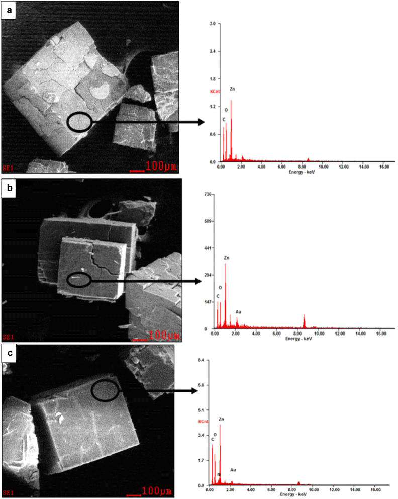 | ||
| Fig. 8 MOF-5 SEM-EDX images synthesis at various conditions (a) 105 °C for 144 h, (b) 120 °C for 24 h, and (c) 140 °C for 12 h. Reproduced from Mulyati et al.73 with permission from Indonesian Journal of Chemistry, copyright 2015. | ||
It is reported that all three samples have cubic morphologies with different particle sizes, which can be categorized as smaller particle size (85–95 μm), and larger particle size (250–300 μm) synthesized at high temperatures (140 °C), shorter time (12 h) and lower temperature and longer time, at 100 °C for 144 and 120 °C for 24 respectively. When the solubility of the precursors is studied, it is discovered that metal salts can only dissolve in strongly polar organic solvents, whereas organic linkers can dissolve in less polar or non-polar organic solvents. As a result, it becomes necessary to combine two or more solvents when conducting synthesis. As a result, the creation of the framework and physical properties can be influenced by the solvent's composition.74 Dietzel et al.75 used 2,5-dihydroxyterephthalic acid as the linker to investigate the impact of solvent change on framework topologies. The system's simplicity was exploited to control how the acidic proton in the side chain dehydrates (hydroxyl group). A three-dimensional nonporous structure with Pts topology [Mg(H2dhtp)(H2O)2] was created using a lower concentration of NaOH (2 mL) in the ethanol/water solvent mixture, and the side chain hydroxyl groups remained protonated. Nevertheless, adding more NaOH (3 mL) to a tetrahydrofuran/water solvent caused the hydroxyl group to dehydrate, which produced MOF-74-Mg, which is made up of 1D helical chains of edge-sharing Mg octahedral. A solvothermal method has been utilized to construct MOFs for hydrogen storage (carboxylate-based, azolate-based, MOFs with mixed ligands and MOFs with metal complexes as building blocks). The setbacks of using the solvothermal method for the construction of MOFs include; lengthy reaction time, large operating temperature, and great cost of the solvent.
5.2 Microwave synthesis
Slow diffusion techniques such as hydrothermal and solvothermal methods have been employed to synthesize various MOFs.76,77 In both approaches, the reaction with the traditional heating method takes a longer duration. Hence, alternative methods such as microwave (MW) have been initiated to synthesize MOFs. A kind of electromagnetic spectrum with a frequency of around 300 to 300![[thin space (1/6-em)]](https://www.rsc.org/images/entities/char_2009.gif) 000 MHz and reasonably large wavelengths of 1 mm to 1 m was described as MW by Baig and Varma.78 The concept of MW, involves supplied thermal energy by the microwave field, which interacts with the electronic structure of the material. The degree to which a material interacts with the electric field is determined by its dielectric properties, namely its dielectric constant and dielectric loss.79 By definition, a material's dielectric constant indicates its capacity to store energy through polarization, whereas its dielectric loss indicates its capacity to transform stored energy into heat. To create MOFs, the solvent must be carefully chosen. The choice of the solvent must meet requirements due to the usage of microwave radiation. The solvent must have the ability to absorb microwave energy and transform electromagnetic energy into heat. A key property, dielectric loss tangent is utilized to assess the potential of the solvent to meet the requirement. The higher the dielectric loss tangent implies that the solvent converts MW energy into heat efficiently. Eqn (1) illustrates the formula for determining the dielectric loss tangent.
000 MHz and reasonably large wavelengths of 1 mm to 1 m was described as MW by Baig and Varma.78 The concept of MW, involves supplied thermal energy by the microwave field, which interacts with the electronic structure of the material. The degree to which a material interacts with the electric field is determined by its dielectric properties, namely its dielectric constant and dielectric loss.79 By definition, a material's dielectric constant indicates its capacity to store energy through polarization, whereas its dielectric loss indicates its capacity to transform stored energy into heat. To create MOFs, the solvent must be carefully chosen. The choice of the solvent must meet requirements due to the usage of microwave radiation. The solvent must have the ability to absorb microwave energy and transform electromagnetic energy into heat. A key property, dielectric loss tangent is utilized to assess the potential of the solvent to meet the requirement. The higher the dielectric loss tangent implies that the solvent converts MW energy into heat efficiently. Eqn (1) illustrates the formula for determining the dielectric loss tangent.
 | (1) |
Microwave development has been used to synthesize various MOFs. Chromium-benzenetricarboxylate (MIL-100-Cr) is produced by Jhung et al.80 using a microwave process from Cr metal, H3BTC, and an aqueous solution of hydrofluoric acid. By using this technique, it was possible to cut the reaction time required to build MIL-100-Cr from 96 to 4 h. Since the reaction time is reduced in MW method, the crystal growth and aggregation rate are limited resulting in obtaining a smaller particle size.81 Hence, it is essential to optimize process parameters such as power input and reaction time to obtain MOFs with satisfactory properties. Using MW-assisted technique, Jhung et al.80 created nanoporous Cr-MIL-101 with diameters ranging from 40 to 90 nm. This was accomplished by changing the heating period from 1 to 40 minutes at 600 W and the energy input from 36 to 1440 kJ. It was discovered that when the crystallization time increases, Cr-dimensions MIL-100's grow and become more uniform. With an increase in energy input, the shape and morphology evolved (from sphere to cubic) (see Fig. 9).
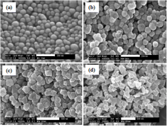 | ||
| Fig. 9 Impact of crystallization time on the morphology of MIL-101 prepared with microwave irradiation at 210 °C for (a) 1, (b) 2, (c) 10, and (d) 40 min. Reproduced from Jhung et al.80 with permission from John Wiley and Sons, copyright 2006. | ||
The impact of the synthesizing circumstances, specifically the temperature and heating technique, on the structure of MOFs was investigated by Seo et al.82 The synthesis of MOF at 120 °C and 170 °C generated Cu3(BTC)2(H2O)3 and [Cu2(BTC)(OH)(H2O)]·2H2O phases respectively. Different MOFs can be constructed effectively, rapidly, and with high yield by using the MC method. Vital properties that affect the scalability of MW assisted technique include, heating parameters, dielectric properties, power efficiency, and power density.83 The major setback in the upscaling of this technology is the lack of data on the properties.
5.3 Mechanochemical synthesis
Mechanochemical technology is one of the techniques used to construct MOFs. The concept of this method is to promote chemical reactions by milling or grinding solid precursors (breaking of intramolecular bonds by mechanical force) without the presence of the solvent or with a minimum amount of the solvent. According to Baig and Varma,78 there's an evolution occurring during the mechanical grinding of solids, which includes, size reduction to small particles, enhanced surfaces, defects and dislocations in the crystalline structure, phase transformation in polymorphic materials, and chemical reactions. The production of MOF particles can be obtained in a short duration normally in the range of 10–60 minutes. In terms of the choice of the precursors, Stock and Biswas71 stated that metal oxide was suitable to be used over metal salts, which results in water as the only by-product. The acceleration of mechanochemical reactions is attributed to the addition of a minimum number of solvents known as liquid-assisted grinding (LAG).Pichon et al.84 were the first to employ mechanochemical free solvent to construct MOF. The reaction was carried out in the steel reactor in which Cu(OAc)2·H2O and isonicotinic acid were ground for 10 minutes with the aid of a steel ball to produce strongly crystalline and one phase result of [Cu(INA)2] with water molecules and acetic acids in pores. The removal of guest molecules can be detached by thermal activation to give the porous compound. The same approach was utilized to synthesize HKUST-1.85 Copper acetate and H3BTC were used as precursors and ball milled for 25 minutes to acquire HKUST-1 with a crystal size of 50 nm in size and a specific surface area of 1713 m2 g−1. Tanaka et al.86 synthesized ZIF-8 by employing mechanosynthesis and conventional processes to assess which method is greatly versatile and effective to attain ZIF-8 with hierarchical superstructure. The use of nanosized ZnO power and zinc acetate made it possible to accelerate the reaction and obtain the best results.
Morphological analysis revealed that rhombic dodecahedral crystals are obtained in the conventional solution (Fig. 10a). The addition of zinc acetate dehydrates in the mechanochemical method affected on the morphology of ZIF-8. Amorphous-looking agglomerates with clearly defined faces and edges can be seen. Zinc acetate was also added, which changed the morphology of the agglomerates from an integrated structure made up of isolated particles to one with dendritic porosity architecture (Fig. 10c). To create nano-sized MOFs, mechanochemical technology provides a quick, easy, and efficient approach to mill a mixture of metal salts and organic ligands. This technology is quicker with high yielding of the product as compared to conventional method. Mechanochemical method does not require additional steps, which are often employed in the solvent method for the removal of entrapped guest molecules that may result in the frame collapsed.
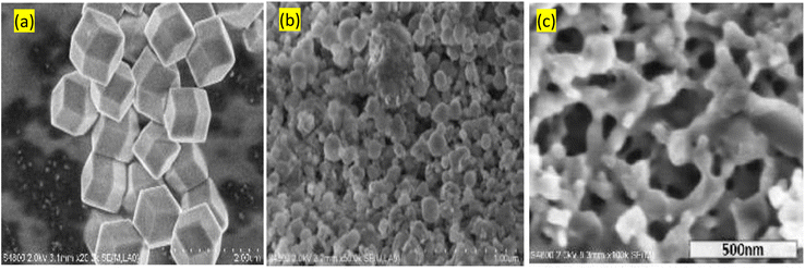 | ||
| Fig. 10 Morphological analysis of ZIF-8 obtained via different approaches (a) conventional monocrystalline (b) mechanochemical using nanosized ZnO without zinc acetate dehydrate (c) with zinc acetate dehydrate. Reproduced from Tanaka et al.86 with permission from American Chemical Society, copyright 2018. | ||
5.4 Sonochemical synthesis
Sonochemistry has become a well-defined method, in which the reaction mixture alters because of exposure to high-energy ultrasound irradiation from 20 kHz to 10 MHz.87 The effect of ultrasound is mainly driven by the acoustic cavitation. The ultrasound in the liquid medium results in pressure fluctuations leading to the formation of growth and implosive collapse of bubbles known as the cavitation process. With both heating and cooling rates of > 1010 K s−1, temperatures of 5000 K, and pressures of 1000 bar, this process increased the energy generated. Suslick,88 indicated that apart from the increased temperature and pressure, the localized hot spots can lead to cavitation-generated shock waves and micro-jets which can cause an effective stirring of the adjusted layer of liquid.The attractiveness of using sonochemical lies in the ability to synthesize MOFs under mild conditions such as at ambient conditions and solvent-free. Qiu et al.90 construct MOF (Zn3(BTC)2) by employing the sonochemical method. As precursors, 20% ethanol was combined with zinc acetate and H3BTC, which were then sonicated for up to 90 minutes. The product had a high yield of 75.3% after only 5 minutes of sonication. In Son et al.91 sonochemical's method was used to create MOF-5. In an inert environment, a solution of zinc nitrate and terephthalic acid in 1-methyl-2-pyrrolidone was combined and sonicated for 10 to 75 minutes. By using this method, the synthesis time was cut from 24 hours (using traditional heating) to 75 minutes. Characteristics of the structure of MOFs (namely the quality of the crystals, particle size, surface area, and pore size) synthesized by sonochemical technique are affected by process parameters such as temperature, solvent type and ratio, reagent concentration, and modulators. Israr et al.89 synthesized Cu-BTC (BTC = 1,3,5-benzene tricarboxylate) using sonochemical technology. They studied the effect of solvent mixtures of water–N,N-dimethylformamide (DMF), and water–ethanol with or without various bases under 20 kHz ultrasonically treated conditions on the morphology of the products (Fig. 11). The deprotonation that leads to crystal formation was promoted by the addition of base in the presence of H2O and ethanol (Fig. 11). Li et al.92 synthesized HKUST-1 by reacting cupric acetate and H3BTC in a mixed solution of DMF/EtOH/H2O under ultrasonic irradiation at ambient conditions for the reaction duration of 5–60 minutes which produced HKUST-1 with a yield of 62.6–85.1%. Among other benefit of using this technique compared to conventional solvothermal is that the obtained nano-crystals have a lower dimensional size in the range of 10–200 nm. Moreover, the sonochemical method for the synthesis of porous MOFs was found to be highly efficient and more environmentally friendly.
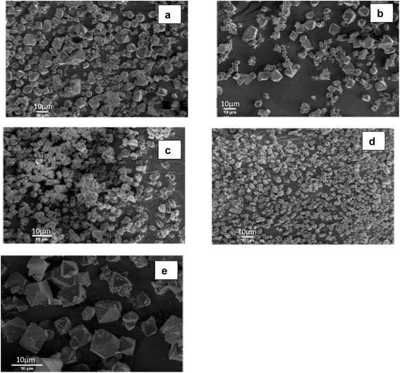 | ||
| Fig. 11 SEM analysis of produce Cu-BTCs under various solvent mixture (a) H2O–DMF, (b) H2O–ethanol–DMF, (c) H2O–ethanol–NaOH, (d) H2O–ethanol–NH4OH, and (e) H2O–ethanol–pridine. Reproduced from Israr et al.89 with permission from Elsevier, copyright 2016. | ||
6. Safety consideration for MOF synthesis
Ensuring that hydrogen is a viable energy carries some obstacles that need to be overcome to promote the hydrogen economy. Among these obstacles, safety is a key factor to be considered, as hydrogen usage and storage come with some risks hence the need for precaution. The construction of MOFs regardless of the method used, either on the laboratory scale or in production is subject to hazards. The synthesis of certain MOFs is carried out in pressure vessels such as autoclave reactors in which one of the hazards is explosion. The Society of Mechanical Engineers (ASME) has developed standards for high-pressure vessels.93 These standards address several pressure related expressions such as design or maximum operating pressure and maximum allowable working pressure. The standard that governs the safety around the usage or design of equipment alone is not sufficient to eliminate the occurrence of incidents. Recently, an incident occurred at the Institute of Chemistry in China where a student was operating a hydrothermal autoclave to construct MOF with dimethylformamide as a solvent. It is reported that human error and operational conditions led to the explosion of the metal vessel. Apart from the developed standards, it is essential during the synthesis of MOFs to conduct hazard identification and analysis, which can be of assistance to minimize or limiting exposure to risks. Lakhe et al.94 reported a safety analysis, which included hazard identification for the production of MXene-type compound. It is vital to identify and mitigate the hazards in all the steps during the synthesis of MOFs.In the mixing step, precursors such as organic linkers and metal salts are mixed. The main hazards associated with raw materials, include toxicity, corrosion, and flammability. It is known that metal ion provides the central node for MOFs. These salts (nitrates, sulfates, or chlorides) are carriers of corrosive hazards in the process. In the synthesis of MOFs solvents are utilized e.g., N-methyl-2-pyrrolidone, strong acids, and bases. The hazards associated with the usage of such solvents include toxicity and explosion. Hazards of the synthesis step are related to the flammability and reactivity of the raw materials, being aggravated by process conditions such as operating temperature and pressure. Lee et al.95 indicated that during the mechanochemical synthesis of MOF such as ZIF-8, the use of ammonium nitrate imposes the risk of explosion. The filtration process is common in the synthesis of various MOFs. This process consists of several stages, which use filters and solvent treatment. The major identified hazard associated with this process and washing is the generation of chemical waste from the solvent used.
7. Effect of selected characteristics of MOFs on hydrogen capacity
7.1 Effect of surface area of MOFs on hydrogen capacity
The surface area of MOFs is affected by many factors, which include the synthesis route (solvothermal, direct mixing, sonochemical, and microwave assisted), precursor concentration, polarity of the solvent, and process parameters (temperature and time). Among other factors, it is expected that the high surface area of MOFs would maximize hydrogen storage capacity. The surface area of MOFs is calculated by either utilizing the Langmuir or Brunauer–Emmett–Teller (BET) equation. The application of Langmuir equation is on materials with uniform surfaces forming a monolayer with the adsorbates whereas BET takes into account multilayer adsorption. Eqn (2) offers the Langmuir adsorption model, which depicts a persistent monolayer of adsorbate molecules interacting with a homogenous sorbent surface.
 | (2) |
The constant equilibrium of the chemical interaction between the adsorbate molecule and the empty side is KeqA, where ΘA is the fractional occupancy of the adsorption sites, pA is the partial pressure of the adsorbate. The Langmuir adsorption model has some restrictions when applied to MOFs, such as localized adsorption in ultra-micro-pores and multilayer adsorption in supermicropores. Thus, the BET adsorbed model is applicable in these situations. The BET adsorption model is represented by eqn (3).
 | (3) |
 In case of MOFs materials, chemical interaction between the uniform sorbent surface and the sorbent surface depends on the organic ligands and metal atoms during the synthesis process of MOFs.
To date, some of the produced MOFs have incredibly high surface area. Chae et al.50 synthesized crystalline Zn4O(1,3,5-benzenetribenzoate)2 known as MOF-177 which is considered as one of the MOFs with a high specific surface area of 4500 m2 g−1 when evaluated at 77 K by nitrogen. This is significantly higher than that of activated carbon (2000 m2 g−1) and zeolite namely zeolite Y (904 m2 g−1). It is known through experimental and calculation results that a linear relationship occurs between the surface area and hydrogen storage capacity measured at 77 K. Preparation of MOF-5 samples, in which the products with different structures were obtained by exploiting the solvent method and drying using three different procedures. The dying conditions were as follows: sample M1 was dried at room temperature for 2 days, sample M2 was dried in the oven at 373 K for 5 h and sample M3 was dried in the vacuum for 2 h at 373 K. The obtained BET surface area of M1, M2 and M3 samples were measured to be 15.8, 143.2 and 516.9 m2 g−1 respectively. The hydrogen capacity of three types of MOFs was measured to be 0.84, 1.17 and 1.57 mmol g−1. The results indicated that different solvent methods have an effect on the structure of MOF-5 and its characteristics namely surface area and porosity. For meso and macro pores, sample M3's heat of adsorption was computed to be 3.68 and 12.45 kJ mol−1, appropriately. These suggest that the interaction between hydrogen molecules and MOF-5 surface is stronger in the macroporous region. Frost et al.22 used simulation on a set of IRMOFs with the same framework topology and surface chemistry to examine the impact of surface area, heat of adsorption, and free volume on hydrogen adsorption capacity. Fig. 11a shows the geometric structure of the assessed IRMOFs.
Fig. 12b presents the effect of surface area on hydrogen adsorption capacity evaluated at intermediate pressure (30 bar). It is evidence that an excellent correlation between surface area and hydrogen uptake is obtainable at the assessed condition. This means IRMOF with higher surface area will have high hydrogen storage capacity. According to Suh et al.21 at high pressure (10–90 bar) at 77 K, there is a favourable link between surface area and hydrogen capacity. At low pressure (1 atm), the hydrogen uptake is correlated with a surface area between 100 and 2000 m2 g−1, though. The interaction between the adsorbent and hydrogen molecules is said to be negatively impacted by a surface area of more than 2000 m2 g−1 at low pressure and 77 K due to the inability to occupy the free space.
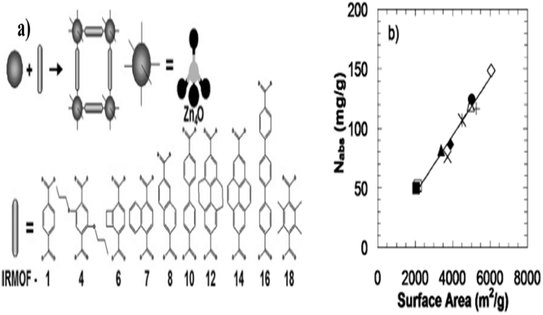 | ||
| Fig. 12 (a) IRMOF chemical structure, building block and geometry and (b) hydrogen adsorption capacity as a function of surface area at 30 bar. Reproduced from Frost et al.22 with permission from American Chemical Society, copyright 2006. | ||
7.2 Effect of crystal shape, size and pore volume of MOFs on hydrogen capacity
The structures of MOFs are classified as either 2 or 3D porous crystalline materials with infinite lattice. According to the IUPAC, porous materials are classified per pore size as microporous (>500 Å), mesoporous (20–500 Å), microporous (<20 Å), super microporous (7–20 Å), and ultra microporous (<7 Å). The adsorption of gases on these materials has different behaviour on the adsorption capacity. For instance, in micropore materials, filling and gas–solid interactions occur at very low pressure. Hence, the rate of adsorption highly depends on temperature. Suresh et al.52 assessed the effect of crystal size distribution and morphologies of MOF-5 on packing efficiency and volumetric hydrogen. In their work, the crystal size distribution was controlled during production. On crystal size and size distribution, the effects of synthesis process variables such temperatures, reagent concentration, and time were assessed. The optimum conditions for the synthesis process obtained were metal![[thin space (1/6-em)]](https://www.rsc.org/images/entities/char_2009.gif) :
:![[thin space (1/6-em)]](https://www.rsc.org/images/entities/char_2009.gif) ligand (3.8
ligand (3.8![[thin space (1/6-em)]](https://www.rsc.org/images/entities/char_2009.gif) :
:![[thin space (1/6-em)]](https://www.rsc.org/images/entities/char_2009.gif) 1, 2.3
1, 2.3![[thin space (1/6-em)]](https://www.rsc.org/images/entities/char_2009.gif) :
:![[thin space (1/6-em)]](https://www.rsc.org/images/entities/char_2009.gif) 1, 1.7
1, 1.7![[thin space (1/6-em)]](https://www.rsc.org/images/entities/char_2009.gif) :
:![[thin space (1/6-em)]](https://www.rsc.org/images/entities/char_2009.gif) 1 and 1.7
1 and 1.7![[thin space (1/6-em)]](https://www.rsc.org/images/entities/char_2009.gif) :
:![[thin space (1/6-em)]](https://www.rsc.org/images/entities/char_2009.gif) 1), 2-fold dilution, temperature (100 °C) and time (24 h).
1), 2-fold dilution, temperature (100 °C) and time (24 h).
The optimized synthesis process conditions resulted in obtaining a submicron average crystal size (Fig. 13a). Fig. 13b shows the synthesized samples exhibit a good correlation between nitrogen uptake and surface area. The usage of crystals with a bimodal size distribution or octahedral morphology, which may condense with few structural flaws and efficiently fill space, is a key to success, according to the authors. Saha et al.5 investigate the effects of various synthesis conditions on the performance of hydrogen adsorption, pore textural characteristics, and crystal structure. They demonstrate that MOF-5 materials with higher order crystallinity produce adsorbents with larger crystal sizes, homogeneous pore size distribution, higher specific surface area, greater hydrogen adsorption capacity, and faster hydrogen diffusion rate. The attractiveness of utilizing MOFs in hydrogen storage is due to the modifiable pore size, pore volume, and geometry. Zhang et al.44 examined several MOFs (NU-125, HKUST-1, UiO-68-Ant, NU-1000, Cu-MOF-74 and Zn2(bdc)2(dabco)2) with channel and cage structures to correlate the pore geometry with hydrogen total adsorption.
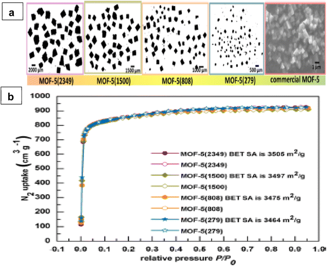 | ||
| Fig. 13 (a) Optical micrographs of four different crystal sizes and SEM image for commercial MOF-5 and (b) Nitrogen sorption isotherms (adsorption data are shown with filled symbols while desorption data are shown with empty symbols). Reproduced from Suresh et al.52 with permission from American Chemical Society, copyright 2021. | ||
The results showed that cage-type MOFs have a higher pore occupancy than channel-type MOFs for the same pore volume (shown in Fig. 14). Yet, as the pore volume grows, the pore occupancy decreases as a result of the reduced interaction potential of adsorption at large pore centers in both scenarios. The total adsorption and pore volume are positively associated up to a pore volume of around 3.3 cm3 g−1. Hydrogen adsorption starts to decrease at pore volumes greater than 3.3 cm3 g−1 as a result of the decreasing pore occupancy at increasing pore volume regions. The authors generated empirical equations to predict total hydrogen adsorption under 100 bar and 77 k for cage-type MOFs as ntot = 0.085 × VP − 0.013 × VP2 and channel-type MOFs as ntot = 0.076 × VP − 0.011 × VP2, where VP denotes the pore volume of the corresponding MOFs. To examine their effects on pore features and hydrogen adsorption, Yang et al.96 produced materials of various qualities (less crystalline, strong crystalline, interwoven, and interwoven with included MWCNTs). The combination of modification and MWCNT insertion in MOF-5 resulted in increased hydrogen adsorption capacity at −196 °C and 1 bar (capacity increased from 1.2 to 2 wt%) and improved thermal stability (decomposition temperature raised from 438 to 510 °C).
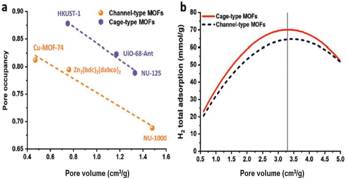 | ||
| Fig. 14 (a) Pore occupancy (100 bar and 77 K) versus pore volume and (b) predicted hydrogen adsorption versus pore volume (100 bar and 77 K) using empirical equations. Reproduced from Zhang et al.97 with permission from John Wiley and Sons, copyright 2020. | ||
Basically, because spherical pores have more exposed surface atoms and are in closer touch with the sorbate molecule than cylindrical pores,97 the sorbate–sorbent interaction potential in spherical pores is larger. According to Lin et al.30 as pressure rises, pore volume becomes more important and pore size has an impact on hydrogen adsorption.
7.3 Effect of exposed metal sides on hydrogen adsorption enthalpy
The generation of unsaturated metal centers during the synthesis of MOFs is essential for hydrogen storage. Liu et al.98 defined the creation of these sites in MOFs crystals are due to previously occupied solvent molecules. The removal of the occupied solvent molecules from the framework is achieved by solvent removal at higher temperatures in which the MOFs can retain its structural integrity and the ability to increase hydrogen capacity.99 An increase in the heat of adsorption of hydrogen in MOF is attributed to better interaction between hydrogen molecules and open metal sites. The influence of the metal nodes as an adsorption site was evaluated by Garcia-Holley and colleagues,100 and the isosteric temperatures of adsorption were computed. Several MOFs with different structures were tested, and the obtained isosteric heat of adsorption varied from 4.5 to 6.6 kJ mol−1. The outcomes showed that the volume density of metal centers does not affect the values for the copper paddlewheel MOFs Cu-MOF-74, NOTT-112, HKUST-1, and NU-125. The isosteric heat of adsorption further demonstrates that neither the interactions nor the hydrogen deliverable capacity is affected by the existence of accessible open metal sides. Vitillo et al.101 examined the contribution of metal sites on hydrogen storage capacity of various MOFs, vis: MOF-5, with unexposed metal sites, HKUST-1 and CPO-27-Ni, with exposed Cu2+ and Ni2+, respectively. Fig. 15 shows a pictorial representative of a hydrogen molecule interacting with the nickel cation and with Ocu or OOH on the exposed metal side. Based on the pure energetic evaluation, the high adsorption enthalpy of −13.5 kJ mol−1 was found for CPO-27-Ni, which suggests that this material is best performing compared to the other two materials. However, the amount of hydrogen stored in these adsorbents measured at 45 bar and 77 K are 1.8% for CPO-27-Ni, 2.7% for HKUST-1 and 3.1% for MOF-5. At this condition, hydrogen storage is dependent mostly on surface area and total pores of the absorbent.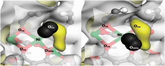 | ||
| Fig. 15 H2 adsorption on the Ni site: pictorial representation of two likely Ni2+ ****H2 adducts. The H atoms of the H2 molecule are represented as black sphere. Yellow areas correspond to a −0.015 au value of the electrostatic potential. Reproduced from Vitillo et al.101 with permission from American Chemical Society, copyright 2008. | ||
By removing the terminal water ligands from the MOF SNU-15 at 220 °C under vacuum, Chae et al.50 produced Co2+ ions containing an open site. It was observed that each Co2+ had an open metal site, which produced a significant isosteric heat of hydrogen adsorption at 0% coverage (15.1 kJ mol−1). According to Gedrich et al.102 positioning of the exposed sites with respect to the hydrogen could maximize hydrogen adsorption. Zeleňák and Saldan103 stated that a method of creating an open metal site by binding substrate without the removal of the ligand should be considered, which involves the alignment of the solvent molecules by the metal aggregates. Kapelewski et al.104 studied the volumetric hydrogen storage capacities of high-performing MOFs: M2 (m-dobdc) (M = Co, Ni; m-dobdc = 4,6-dioxido-1,3-benzenedicarboxylate) and the isomeric frameworks M2 (dobdc) (M = Co, Ni; dobdc = 1,4-dioxido-1,3-benzenedicarboxylate), consisting of an open metal cation site that strongly interacts with hydrogen molecules. The results show that Ni2 (m-dobdc) performs better than other materials with a volumetric capacity of 11 g L−1 and 23 g L−1 measured at the temperature range of −75 and 25 °C and pressure of 100 and 5 bar respectively. Exposed metal cation locations (polarizing Ni2+), which have a significant interaction with hydrogen molecules, were found to be responsible for these outcomes.
8. Conclusion and outlook
Several techniques are used to store hydrogen. High-pressure tanks are the most widely used method of storing hydrogen, although this method has serious protection and energy effectiveness concerns. Besides compressed and liquefied hydrogen storage, material-based technology proven to achieve efficient energy storage and it is reliable and safe. Metal organic structures are a type of crystalline porous material that has seen considerable interest in applications for hydrogen absorption. This is mostly due to their distinctive qualities, which include their large surface area, large pore volume, and modifiable structure. The most common technology employed in the construction of MOFs is solvochemical. However, this method requires a longer reaction duration, which leads to obtaining larger crystals. In contrast, microwave and sonochemical methods, have shorter reaction duration mainly because of the concentrated and localized energy of the reactive mixture. Besides the short reaction duration in the microwave assist method, MOFs properties such as morphology, particle size, and phase are controlled by the optimization of parameters such as the applied power and treatment time. In sonochemical method, the synthesis parameters have a direct impact on the properties of the final product. The attraction of this method is mainly due to the promoted nucleation and crystallization time. Using MOFs for hydrogen energy storage possesses potential significance compared to other techniques including hydrogen storage in metal hydrides. The significant potentials of the MOFs are due to their reversibility, high rate of hydrogen adsorption, ability to detect contaminants, high micropores connectivity, high specific surface area, modifiable pores size, multifunctional properties, etc. However, there are still some limitations facing MOFs, which limit some of their applications. These limitations are related to very low-temperature operation, poor stability, selectivity and electrical conductivity, cost ineffective, low storage or capturing capacity, poor recyclability, poor reactivation by heat treatment, leaching off metal ions by solvents, toxicity, scalability, functionalization challenge, etc. Poor thermal, mechanical, chemical, or structural stability of MOFs are issues of concern as they become unstable in the presence of humidity and some chemicals or even collapse under certain conductions. The scalability challenge of the MOFs and the cost ineffectiveness of MOFs due to the use of certain chemicals and synthesizing methods have hindered their wide engineering applications. In addition, MOFs also have challenges of selectivity for certain gases and may contain toxic elements or components as bye products or during synthesis. Therefore, there is a need for further research and development of advanced MOFs that address these challenges for advanced engineering applications. The research perspective and directions towards achieving advanced MOFs could be on the synthesis approaches as they have a significant influence on the final properties of the MOFs such as electrical and catalytic properties. For instance, the fabrication of MOFs should focus on obtaining suitable density, large surface area, pore volume, and stability of the frameworks simultaneously. Development of advanced MOFs nanocomposites by incorporating carbon-based and metal hybrids nanomaterials could also address the faced challenges of the MOFs. The incorporation of nanomaterials could be highly functionalized to promote relationship and synergy between them and MOFs, provide large active sites, improve catalytic performance, large electrical conductivity output and enhance stability. Various advanced materials treatments such as carbonization, heat and acid treatments could be added approaches towards MOFs with desired properties for various applications. Finally, there is a high need in the investigation for scalability, reproducibility, and cost-reduction approaches for the fabrication of MOFs, which will involve scientists from different disciplines and fields.Data availability
There is no generated data associated with this study.Author contributions
John Letwaba: conceptualization and writing – original draft. Uwa Orji Uyor: validation, review, and final editing/proof reading. Mapula Lucey Mavhungu: supervision, and funding acquisition. Oji Nwoke Achuka: data curation, review and editing. Patricia Abimbola Popoola: supervision, and funding acquisition.Conflicts of interest
The authors have no competing interests to declare that are relevant to the content of this article.Acknowledgements
No funding was received to assist with the preparation of this manuscript. The authors would love to appreciate Tshwane University of Technology for their support towards this study.References
- O. J. Oladunni, K. Mpofu and O. A. Olanrewaju, Greenhouse gas emissions and its driving forces in the transport sector of South Africa, Energy Rep., 2022, 8, 2052–2061 CrossRef.
- S.-Y. Lee, J.-H. Lee, Y.-H. Kim, J.-W. Kim, K.-J. Lee and S.-J. Park, Recent progress using solid-state materials for hydrogen storage: a short review, Processes, 2022, 10(2), 304 CrossRef CAS.
- A. Noguera-Díaz, N. Bimbo, L. T. Holyfield, I. Y. Ahmet, V. P. Ting and T. J. Mays, Structure–property relationships in metal-organic frameworks for hydrogen storage, Colloids Surf., A, 2016, 496, 77–85 CrossRef.
- E. Rivard, M. Trudeau and K. Zaghib, Hydrogen storage for mobility: a review, Materials, 2019, 12(12), 1973 CrossRef CAS PubMed.
- D. Saha, S. Deng and Z. Yang, Hydrogen adsorption on metal-organic framework (MOF-5) synthesized by DMF approach, J. Porous Mater., 2009, 16, 141–149 CrossRef CAS.
- H. Daglar, et al., Effect of metal–organic framework (MOF) database selection on the assessment of gas storage and separation potentials of MOFs, Angew. Chem., Int. Ed., 2021, 60(14), 7828–7837 CrossRef CAS PubMed.
- J. Camp, V. Stavila, M. D. Allendorf, D. Prendergast and M. Haranczyk, Critical factors in computational characterization of hydrogen storage in metal–organic frameworks, J. Phys. Chem. C, 2018, 122(33), 18957–18967 CrossRef CAS.
- D. E. Jaramillo, et al., Ambient-temperature hydrogen storage via vanadium(II)-dihydrogen complexation in a metal–organic framework, J. Am. Chem. Soc., 2021, 143(16), 6248–6256 CrossRef CAS PubMed.
- M. Liu, Y. Liu, X. Liu, C. Chu, D. Yao and S. Mao, Modification strategies on 2D Ni-Fe MOF-based catalysts in peroxydisulfate activation for efficient organic pollutant removal, Chin. Chem. Lett., 2023, 34(4), 107708 CrossRef CAS.
- T. Zhao, et al., MOF-derived nitrogen-doped iron–nickel oxide carbon nanotubes as efficient oxygen electrocatalyst for long-life rechargeable zinc–air batteries, Rare Metals, 2023, 42(10), 3326–3336 CrossRef CAS.
- P. Feng, W. Hou, Z. Bai, Y. Bai, K. Sun and Z. Wang, Ultrathin two-dimensional bimetal NiCo-based MOF nanosheets as ultralight interlayer in lithium-sulfur batteries, Chin. Chem. Lett., 2023, 34(4), 107427 CrossRef CAS.
- X.-L. Liu, J.-W. Guo, Y.-W. Wang, A.-Z. Wang, X. Yu and L.-H. Ding, A flexible electrochemical sensor for paracetamol based on porous honeycomb-like NiCo-MOF nanosheets, Rare Metals, 2023, 42(10), 3311–3317 CrossRef CAS.
- S.-K. Le, et al., Rare earth element-modified MOF materials: synthesis and photocatalytic applications in environmental remediation, Rare Metals, 2024, 1–17 CAS.
- R. Bhattacharyya and S. Mohan, Solid state storage of hydrogen and its isotopes: an engineering overview, Renew. Sustainable Energy Rev., 2015, 41, 872–883 CrossRef CAS.
- J. Goldsmith, A. G. Wong-Foy, M. J. Cafarella and D. J. Siegel, Theoretical limits of hydrogen storage in metal–organic frameworks: opportunities and trade-offs, Chem. Mater., 2013, 25(16), 3373–3382 CrossRef CAS.
- H. Furukawa, et al., Ultrahigh porosity in metal–organic frameworks, Science, 2010, 329(5990), 424–428 CrossRef CAS PubMed.
- S. S.-Y. Chui, S. M.-F. Lo, J. P. Charmant, A. G. Orpen and I. D. Williams, A chemically functionalizable nanoporous material [Cu3(TMA)2(H2O)3]n, Science, 1999, 283(5405), 1148–1150 CrossRef CAS PubMed.
- Y. Tian, C. Cai, Y. Ji, X. You, S. Peng and G. Lee, ZUSCHRIFTEN-(Co5 (im) 10. 2MB)(infinity): a metal–organic open-framework with zeolite-like topology, Angew. Chem., Int. Ed. Engl., 2002, 114(8), 1442–1443 CrossRef.
- Y. Q. Tian, et al., The silica-like extended polymorphism of cobalt(II) imidazolate three-dimensional frameworks: X-ray single-crystal structures and magnetic properties, Chem.–Eur. J., 2003, 9(22), 5673–5685 CrossRef CAS PubMed.
- Y. Q. Tian, Y. M. Zhao, Z. X. Chen, G. N. Zhang, L. H. Weng and D. Y. Zhao, Design and generation of extended zeolitic metal–organic frameworks (ZMOFs): synthesis and crystal structures of zinc(II) imidazolate polymers with zeolitic topologies, Chem.–Eur. J., 2007, 13(15), 4146–4154 CrossRef CAS PubMed.
- M. P. Suh, H. J. Park, T. K. Prasad and D.-W. Lim, Hydrogen storage in metal–organic frameworks, Chem. Rev., 2012, 112(2), 782–835 CrossRef CAS PubMed.
- H. Frost, T. Düren and R. Q. Snurr, Effects of surface area, free volume, and heat of adsorption on hydrogen uptake in metal–organic frameworks, J. Phys. Chem. B, 2006, 110(19), 9565–9570 CrossRef CAS PubMed.
- J. Kim, S. Yeo, J.-D. Jeon and S.-Y. Kwak, Enhancement of hydrogen storage capacity and hydrostability of metal–organic frameworks (MOFs) with surface-loaded platinum nanoparticles and carbon black, Microporous Mesoporous Mater., 2015, 202, 8–15 CrossRef CAS.
- US Department of Energy, Target Explanation Document: Onboard Hydrogen Storage for Light-Duty Fuel Cell Vehicles, the US DRIVE Partnership, 2017 Search PubMed.
- I. Hassan, H. S. Ramadan, M. A. Saleh and D. Hissel, Hydrogen storage technologies for stationary and mobile applications: review, analysis and perspectives, Renew. Sustainable Energy Rev., 2021, 149, 111311 CrossRef CAS.
- K. K. Gangu, S. Maddila, S. B. Mukkamala and S. B. Jonnalagadda, Characteristics of MOF, MWCNT and graphene containing materials for hydrogen storage: a review, J. Energy Chem., 2019, 30, 132–144 CrossRef.
- S. Verhelst, Recent progress in the use of hydrogen as a fuel for internal combustion engines, Int. J. Hydrogen Energy, 2014, 39(2), 1071–1085 CrossRef CAS.
- K. P. Brooks, T. A. Semelsberger, K. L. Simmons and B. van Hassel, Slurry-based chemical hydrogen storage systems for automotive fuel cell applications, J. Power Sources, 2014, 268, 950–959 CrossRef CAS.
- D. Silambarasan, V. Surya, V. Vasu and K. Iyakutti, Single walled carbon nanotube–metal oxide nanocomposites for reversible and reproducible storage of hydrogen, ACS Appl. Mater. Interfaces, 2013, 5(21), 11419–11426 CrossRef CAS.
- X. Lin, W. Xie, Q. Zhu, H. Yang and Q. Li, Rational optimization of metal hydride tank with LaNi4.25Al0.75 as hydrogen storage medium, Chem. Eng. J., 2021, 421, 127844 CrossRef CAS.
- I. Ghosh, S. Naskar and S. S. Bandyopadhyay, Cryosorption storage of gaseous hydrogen for vehicular application–a conceptual design, Int. J. Hydrogen Energy, 2010, 35(1), 161–168 CrossRef CAS.
- G. Hermosilla-Lara, G. Momen, P. Marty, B. Le Neindre and K. Hassouni, Hydrogen storage by adsorption on activated carbon: investigation of the thermal effects during the charging process, Int. J. Hydrogen Energy, 2007, 32(10–11), 1542–1553 CrossRef CAS.
- B. Sakintuna, F. Lamari-Darkrim and M. Hirscher, Metal hydride materials for solid hydrogen storage: a review, Int. J. Hydrogen Energy, 2007, 32(9), 1121–1140 CrossRef CAS.
- R. Moradi and K. M. Groth, Hydrogen storage and delivery: review of the state of the art technologies and risk and reliability analysis, Int. J. Hydrogen Energy, 2019, 44(23), 12254–12269 CrossRef CAS.
- H. Barthélémy, M. Weber and F. Barbier, Hydrogen storage: recent improvements and industrial perspectives, Int. J. Hydrogen Energy, 2017, 42(11), 7254–7262 CrossRef.
- F. Zhang, P. Zhao, M. Niu and J. Maddy, The survey of key technologies in hydrogen energy storage, Int. J. Hydrogen Energy, 2016, 41(33), 14535–14552 CrossRef CAS.
- H. Q. Nguyen and B. Shabani, Review of metal hydride hydrogen storage thermal management for use in the fuel cell systems, Int. J. Hydrogen Energy, 2021, 46(62), 31699–31726 CrossRef CAS.
- Z. Hang, Z. Hu, X. Xiao, R. Jiang and M. Zhang, Enhancing hydrogen storage kinetics and cycling properties of namgh3 by 2d transition metal carbide mxene ti3c2, Processes, 2021, 9(10), 1690 CrossRef CAS.
- J.-H. Park and S.-J. Park, Expansion of effective pore size on hydrogen physisorption of porous carbons at low temperatures with high pressures, Carbon, 2020, 158, 364–371 CrossRef CAS.
- S. Ubaid, R. Zacharia, J. Xiao, R. Chahine, P. Bénard and P. Tessier, Effect of flowthrough cooling heat removal on the performances of MOF-5 cryo-adsorptive hydrogen reservoir for bulk storage applications, Int. J. Hydrogen Energy, 2015, 40(30), 9314–9325 CrossRef CAS.
- D. Zhao, D. Yuan and H.-C. Zhou, The current status of hydrogen storage in metal–organic frameworks, Energy Environ. Sci., 2008, 1(2), 222–235 RSC.
- K. Sillar, A. Hofmann and J. Sauer, Ab initio study of hydrogen adsorption in MOF-5, J. Am. Chem. Soc., 2009, 131(11), 4143–4150 CrossRef CAS PubMed.
- P. Ramirez-Vidal, et al., A step forward in understanding the hydrogen adsorption and compression on activated carbons, ACS Appl. Mater. Interfaces, 2021, 13(10), 12562–12574 CrossRef CAS PubMed.
- H. Zhang, Y. Zhu, Q. Liu and X. Li, Preparation of porous carbon materials from biomass pyrolysis vapors for hydrogen storage, Appl. Energy, 2022, 306, 118131 CrossRef CAS.
- L. Naheed, et al., Hydrogen adsorption properties of carbide-derived carbons at ambient temperature and high pressure, Int. J. Hydrogen Energy, 2021, 46(29), 15761–15772 CrossRef CAS.
- J.-H. Lee and S.-J. Park, Recent advances in preparations and applications of carbon aerogels: a review, Carbon, 2020, 163, 1–18 CrossRef CAS.
- Y.-K. Choi and S.-J. Park, Hydrogen storage capacity of highly porous carbons synthesized from biomass-derived aerogels, Carbon Lett., 2015, 16(2), 127–131 CrossRef.
- Y.-K. Choi and S.-J. Park, Preparation and characterization of sucrose-based microporous carbons for increasing hydrogen storage, J. Ind. Eng. Chem., 2015, 28, 32–36 CrossRef CAS.
- S. B. Singh and M. De, Effects of gaseous environments on physicochemical properties of thermally exfoliated graphene oxides for hydrogen storage: a comparative study, J. Porous Mater., 2021, 28, 875–888 CrossRef CAS.
- H. K. Chae, et al., A route to high surface area, porosity and inclusion of large molecules in crystals, Nature, 2004, 427(6974), 523–527 CrossRef CAS PubMed.
- S. Kitagawa, R. Kitaura and S. i. Noro, Functional porous coordination polymers, Angew. Chem., Int. Ed., 2004, 43(18), 2334–2375 CrossRef CAS PubMed.
- K. Suresh, D. Aulakh, J. Purewal, D. J. Siegel, M. Veenstra and A. J. Matzger, Optimizing hydrogen storage in MOFs through engineering of crystal morphology and control of crystal size, J. Am. Chem. Soc., 2021, 143(28), 10727–10734 CrossRef CAS PubMed.
- X.-J. Li, et al., Construction of two microporous metal–organic frameworks with flu and pyr topologies based on Zn4(μ3-OH)2(CO2)6 and Zn6(μ6-O)(CO2)6 secondary building units, Inorg. Chem., 2014, 53(2), 1032–1038 CrossRef CAS PubMed.
- V. V. e. Butova, M. A. Soldatov, A. A. Guda, K. A. Lomachenko and C. Lamberti, Metal–organic frameworks: structure, properties, methods of synthesis and characterization, Russ. Chem. Rev., 2016, 85(3), 280 CrossRef CAS.
- M. Almasi, et al., Microporous lead–organic framework for selective CO2 adsorption and heterogeneous catalysis, Inorg. Chem., 2018, 57(4), 1774–1786 CrossRef CAS PubMed.
- M. Almáši, V. Zeleňák, P. Palotai, E. Beňová and A. Zeleňáková, Metal–organic framework MIL-101 (Fe)-NH2 functionalized with different long-chain polyamines as drug delivery system, Inorg. Chem. Commun., 2018, 93, 115–120 CrossRef.
- T. Tian, et al., A sol–gel monolithic metal–organic framework with enhanced methane uptake, Nat. Mater., 2018, 17(2), 174–179 CrossRef CAS PubMed.
- S. Henke, W. Li and A. K. Cheetham, Guest-dependent mechanical anisotropy in pillared-layered soft porous crystals–a nanoindentation study, Chem. Sci., 2014, 5(6), 2392–2397 RSC.
- L. R. Redfern and O. K. Farha, Mechanical properties of metal–organic frameworks, Chem. Sci., 2019, 10(46), 10666–10679 RSC.
- N. C. Burtch, J. Heinen, T. D. Bennett, D. Dubbeldam and M. D. Allendorf, Mechanical properties in metal–organic frameworks: emerging opportunities and challenges for device functionality and technological applications, Adv. Mater., 2018, 30(37), 1704124 CrossRef PubMed.
- R. Sule, A. K. Mishra and T. T. Nkambule, Recent advancement in consolidation of MOFs as absorbents for hydrogen storage, Int. J. Energy Res., 2021, 45(9), 12481–12499 CrossRef CAS.
- G. E. Decker and E. D. Bloch, Using helium pycnometry to study the apparent densities of metal–organic frameworks, ACS Appl. Mater. Interfaces, 2021, 13(44), 51925–51932 CrossRef CAS PubMed.
- V. V. Zeleňák and I. Saldan, Factors affecting hydrogen adsorption in metal–organic frameworks: a short review, Nanomaterials, 2021, 11(7), 1638 CrossRef PubMed.
- S. Dengrong, S. Fangxiang, D. Xiaoyu and Z. Li, Mixed-metal strategy on metal–organic frameworks (MOFs) for functionalities expansion: co substitution induces aerobic oxidation of cyclohexene over inactive Ni-MOF-74, J. Inorg. Chem., 2015, 54(17), 8639–8643 CrossRef PubMed.
- C. Angewandte, T. Daqiang, S. Danfeng and H.-C. Zhou, An isoreticular series of metal–organic frameworks with dendritic hexacarboxylate ligands and exceptionally high gas-uptake capacity, Angew. Chem., Int. Ed. Engl., 2010, 5357–5361 Search PubMed.
- B. A. Halford, Lowest density MOF to date, Chem. Eng. News, 2017, 6 Search PubMed.
- J. Purewal, D. Liu and J. Yang, Increased volumetric hydrogen uptake of MOF-5 by powder densification, Int. J. Hydrogen Energy, 2012, 37(3), 2723–2727 CrossRef CAS.
- O. Ardelean, G. Blanita and G. Borodi, Volumetric hydrogen adsorption capacity of densified MIL-101 monoliths, Int J. Hydrogen Energy, 2013, 38(17), 7046–7055 CrossRef CAS.
- J. Dhainaut, C. Avci-Camur and J. Troyano, Systematic study of the impact of MOF densification into tablets on textural and mechanical properties, Cryst. Eng. Comm., 2017, 19(29), 4211–4218 RSC.
- The Chemistry of Metal–Organic Frameworks: Synthesis, Characterization, and Applications, ed. S. Kaskel, John Wiley & Sons, 2016, vol. 2 Search PubMed.
- N. Stock and S. Biswas, Synthesis of metal–organic frameworks (MOFs): routes to various MOF topologies, morphologies, and composites, Chem. Rev., 2012, 112(2), 933–969 CrossRef CAS PubMed.
- D. Banerjee and J. B. Parise, Recent advances in s-block metal carboxylate networks, Cryst. Growth Design, 2011, 11(10), 4704–4720 CrossRef CAS.
- T. A. Mulyati, R. Ediati and A. Rosyidah, Influence of solvothermal temperatures and times on crystallinity and morphology of MOF-5, Indones. J. Chem., 2015, 15(2), 101–107 CrossRef CAS.
- D. Banerjee, et al., Synthesis and structural characterization of magnesium based coordination networks in different solvents, Cryst. Growth Design, 2011, 11(6), 2572–2579 CrossRef CAS.
- P. D. Dietzel, R. Blom and H. Fjellvåg, Base-induced formation of two magnesium metal-organic framework compounds with a bifunctional tetratopic ligand, Eur. J. Inorg. Chem., 2008, 3624–3632 CrossRef CAS.
- G. Férey, Hybrid porous solids: past, present, future, Chem. Soc. Rev., 2008, 37(1), 191–214 RSC.
- A. K. Cheetham, C. Rao and R. K. Feller, Structural diversity and chemical trends in hybrid inorganic–organic framework materials, Chem. Commun., 2006,(46), 4780–4795 RSC.
- R. N. Baig and R. S. Varma, Alternative energy input: mechanochemical, microwave and ultrasound-assisted organic synthesis, Chem. Soc. Rev., 2012, 41(4), 1559–1584 RSC.
- I. Thomas-Hillman, A. Laybourn, C. Dodds and S. W. Kingman, Realising the environmental benefits of metal–organic frameworks: recent advances in microwave synthesis, J. Mater. Chem. A, 2018, 6(25), 11564–11581 RSC.
- S. H. Jhung, J. H. Lee, J. W. Yoon, C. Serre, G. Férey and J. S. Chang, Microwave synthesis of chromium terephthalate MIL-101 and its benzene sorption ability, Adv. Mater., 2007, 19(1), 121–124 CrossRef CAS.
- J. Klinowski, F. A. A. Paz, P. Silva and J. Rocha, Microwave-assisted synthesis of metal–organic frameworks, Dalton Trans., 2011, 40(2), 321–330 RSC.
- Y.-K. Seo, G. Hundal, I. T. Jang, Y. K. Hwang, C.-H. Jun and J.-S. Chang, Microwave synthesis of hybrid inorganic–organic materials including porous Cu3(BTC)2 from Cu(II)-trimesate mixture, Microporous Mesoporous Mater., 2009, 119(1–3), 331–337 CrossRef CAS.
- A. Laybourn, et al., Metal–organic frameworks in seconds via selective microwave heating, J. Mater. Chem. A, 2017, 5(16), 7333–7338 RSC.
- A. Pichon, A. Lazuen-Garay and S. L. James, Solvent-free synthesis of a microporous metal–organic framework, CrystEngComm, 2006, 8(3), 211–214 RSC.
- M. Klimakow, P. Klobes, A. F. Thünemann, K. Rademann and F. Emmerling, Mechanochemical synthesis of metal–organic frameworks: a fast and facile approach toward quantitative yields and high specific surface areas, Chem. Mater., 2010, 22(18), 5216–5221 CrossRef CAS.
- S. Tanaka, T. Nagaoka, A. Yasuyoshi, Y. Hasegawa and J. F. Denayer, Hierarchical pore development of ZIF-8 MOF by simple salt-assisted mechanosynthesis, Cryst. Growth Des., 2018, 18(1), 274–279 CrossRef CAS.
- A. Schoedel, C. Scherb and T. Bein, Oriented nanoscale films of metal–organic frameworks by room-temperature gel-layer synthesis, Angew. Chem., Int. Ed. Engl., 2010, 122(40), 7383–7386 CrossRef.
- K. S. Suslick, Sonochemistry, Science, 1990, 247(4949), 1439–1445 CrossRef CAS PubMed.
- F. Israr, D. K. Kim, Y. Kim, S. J. Oh, K. C. Ng and W. Chun, Synthesis of porous Cu-BTC with ultrasonic treatment: effects of ultrasonic power and solvent condition, Ultrason. Sonochem., 2016, 29, 186–193 CrossRef CAS.
- L.-G. Qiu, Z.-Q. Li, Y. Wu, W. Wang, T. Xu and X. Jiang, Facile synthesis of nanocrystals of a microporous metal–organic framework by an ultrasonic method and selective sensing of organoamines, Chem. Commun., 2008, 31, 3642–3644 RSC.
- W.-J. Son, J. Kim, J. Kim and W.-S. Ahn, Sonochemical synthesis of MOF-5, Chem. Commun., 2008,(47), 6336–6338 RSC.
- Z.-Q. Li, et al., Ultrasonic synthesis of the microporous metal–organic framework Cu3(BTC)2 at ambient temperature and pressure: an efficient and environmentally friendly method, Mater. Lett., 2009, 63(1), 78–80 CrossRef CAS.
- API, API 510: Pressure Vessel Inspection Code: In-Service Inspection, Rating, Repair, and Alteration, American Petroleum Institute, 2006 Search PubMed.
- P. Lakhe, et al., Process safety analysis for Ti3C2Tx MXene synthesis and processing, Ind. Eng. Chem. Res., 2019, 58(4), 1570–1579 CrossRef CAS.
- Y.-R. Lee, M.-S. Jang, H.-Y. Cho, H.-J. Kwon, S. Kim and W.-S. Ahn, ZIF-8: a comparison of synthesis methods, Chem. Eng. J., 2015, 271, 276–280 CrossRef CAS.
- S. J. Yang, H. Jung, T. Kim, J. H. Im and C. R. Park, Effects of structural modifications on the hydrogen storage capacity of MOF-5, Int. J. Hydrogen Energy, 2012, 37(7), 5777–5783 CrossRef CAS.
- X. Zhang, et al., Optimization of the pore structures of MOFs for record high hydrogen volumetric working capacity, Adv. Mater., 2020, 32(17), 1907995 CrossRef CAS PubMed.
- Y. Liu, et al., Assembly of metal–organic frameworks (MOFs) based on indium-trimer building blocks: a porous MOF with soc topology and high hydrogen storage, Angew. Chem., Int. Ed. Engl., 2007, 119(18), 3342–3347 CrossRef.
- M. Ahmadi, et al., An investigation of affecting factors on MOF characteristics for biomedical applications: a systematic review, Heliyon, 2021, 7(4), e06914 CrossRef CAS PubMed.
- P. García-Holley, et al., Benchmark study of hydrogen storage in metal–organic frameworks under temperature and pressure swing conditions, ACS Energy Lett., 2018, 3(3), 748–754 CrossRef.
- J. G. Vitillo, et al., Role of exposed metal sites in hydrogen storage in MOFs, J. Am. Chem. Soc., 2008, 130(26), 8386–8396 CrossRef CAS PubMed.
- K. Gedrich, et al., A highly porous metal–organic framework with open nickel sites, Angew. Chem., Int. Ed., 2010, 49(45), 8489–8492 CrossRef CAS PubMed.
- V. Zeleňák and I. Saldan, Factors affecting hydrogen adsorption in metal–organic frameworks: a short review, Nanomaterials, 2021, 11(7), 1638 CrossRef PubMed.
- M. T. Kapelewski, et al., Record high hydrogen storage capacity in the metal–organic framework Ni2(m-dobdc) at near-ambient temperatures, Chem. Mater., 2018, 30(22), 8179–8189 CrossRef CAS PubMed.
| This journal is © The Royal Society of Chemistry 2024 |
