 Open Access Article
A surface-modified Na3V2(PO4)2F3 cathode with high rate capability and cycling stability for sodium ion batteries
Jiexin Zhang ,
Congrui Zhang,
Yu Han,
Xingyu Zhao,
Wenjie Liu and
Yi Ding*
State Key Laboratory of Advanced Power Transmission Technology (State Grid Smart Grid Research Institute Co. Ltd), Beijing 102209, China. E-mail: dyadin@sina.com
First published on 25th April 2024
Abstract
High voltage, high rate, and cycling-stable cathodes are urgently needed for development of commercially viable sodium ion batteries (SIBs). Herein, we report a facial ball-milling to synthesize a carbon-coated Na3V2(PO4)2F3 composite (C-NVPF). Benefiting from the highly conductive carbon layer, the C-NVPF material exhibits a high reversible capacity (110.6 mA h g−1 at 0.1C), long-term cycle life (54% of capacity retention up to 2000 cycles at 5C), and excellent rate performance (35.1 mA h g−1 at 30C). The present results suggest promising applications of the C-NVPF material as a high-performance cathode for sodium ion batteries.
1. Introduction
Sodium ion batteries have been considered as a promising alternative to Li-ion batteries for energy storage applications because of the low cost and abundant resources of sodium.1–3 However, it is hard to find suitable host materials for reversible Na ion insertion/removal due to the larger size and sluggish diffusion kinetics of Na ions as compared to Li ions. In the past few years, many studies have focused on a variety of cathode host materials such as transition-metal oxides,4–9 phosphates,10–15 and ferrocyanides16,17 that have been explored as potential cathodes for sodium ion batteries (SIBs), which show a relatively high operating voltage (∼3.0 V). However, most of the reported cathode materials displayed either multiple charge–discharge steps or poor cycling stability, hindering battery applications. In contrast, Na3V2(PO4)2F3 appears to be an appealing candidate for Na-ion battery cathodes due to its high working voltage plateau, excellent rate capability, and cycling stability.18–20Na3V2(PO4)2F3 was first studied as a cathode material for lithium-ion batteries and reported by Barker's group in 2006,21,22 and Na3V2(PO4)2F3 as a cathode material for sodium-ion batteries was first reported by Shakoor.23 Since then, many efforts have been devoted to improving the electrochemical performance of Na3V2(PO4)2F3 by doping, carbon coating and nanoarchitecturing.24–30 Recently, Liu et al.25 synthesized a carbon-coated Na3V2(PO4)2F3 composite with a specific capacity of 130 mA h g−1 that can be stably cycled for 3000 cycles. Shen et al.26 prepared the NVPF@C/CNT complex by spray drying with a capacity of 85 mA h g−1 at 30C. Li et al.27 widened the ion diffusion channel by doping potassium at the vanadium position, and the material had a capacity of 120 mA h g−1 at 1C, a capacity of 90 mA h g−1 after 1600 cycles at 10C, and a capacity retention rate of 90% after 6000 cycles at 50C. Broux29 assembled the 18![[thin space (1/6-em)]](https://www.rsc.org/images/entities/char_2009.gif) 650 battery by using Na3V2(PO4)2F3 as the positive electrode and hard carbon as the negative electrode, which had an energy density of 75 W h kg−1, and exhibited good electrochemical performance even at 0 °C. For the question of whether the third sodium ion in Na3V2(PO4)2F3 can be shed, Tarascon's research group has carried out some research in this field. They demonstrated through solid-state NMR and other characterization techniques and the experimental result shows that Na3V2(PO4)2F3 can achieve reversible intercalation of the third sodium ion when the cut-off voltage is reduced to 1.0 V, which broaden the scope of its use.
650 battery by using Na3V2(PO4)2F3 as the positive electrode and hard carbon as the negative electrode, which had an energy density of 75 W h kg−1, and exhibited good electrochemical performance even at 0 °C. For the question of whether the third sodium ion in Na3V2(PO4)2F3 can be shed, Tarascon's research group has carried out some research in this field. They demonstrated through solid-state NMR and other characterization techniques and the experimental result shows that Na3V2(PO4)2F3 can achieve reversible intercalation of the third sodium ion when the cut-off voltage is reduced to 1.0 V, which broaden the scope of its use.
However, building a better conductive layer by more facile synthesis still remains a challenge for development of commercially viable Na3V2(PO4)2F3/C material. Carbon appears to be an ideal coating material for building a conductive framework for high performance electrodes because of its superior electronic conductivity and structural flexibility. As a result, the as prepared C-NVPF electrode demonstrated a high Na storage capacity (110.6 mA h g−1 at 0.1C) with superior cycling stability (54% of capacity retention over 2000 cycles at 5C) and high rate capability (35.1 mA h g−1 at 30C), showing a promising application for sodium ion batteries.
2. Materials and methods
2.1 Materials synthesis
![[thin space (1/6-em)]](https://www.rsc.org/images/entities/char_2009.gif) : citric acid = 5
: citric acid = 5![[thin space (1/6-em)]](https://www.rsc.org/images/entities/char_2009.gif) :
:![[thin space (1/6-em)]](https://www.rsc.org/images/entities/char_2009.gif) 1) was added during the ball milling process. Then, an appropriate amount of ethanol was added to the mixture for 6 h ball milling and dried the mixture in an oven at 80 °C to obtain the precursor. Finally, the precursor was calcined at 600 °C for 6 h in an atmosphere of Ar to obtain the final product Na3V2(PO4)2F3, marked as bare-NVPF.
1) was added during the ball milling process. Then, an appropriate amount of ethanol was added to the mixture for 6 h ball milling and dried the mixture in an oven at 80 °C to obtain the precursor. Finally, the precursor was calcined at 600 °C for 6 h in an atmosphere of Ar to obtain the final product Na3V2(PO4)2F3, marked as bare-NVPF.![[thin space (1/6-em)]](https://www.rsc.org/images/entities/char_2009.gif) :
:![[thin space (1/6-em)]](https://www.rsc.org/images/entities/char_2009.gif) 1, and the resulting material is marked as C-NVPF.
1, and the resulting material is marked as C-NVPF.2.2 Materials characterization
Transmission electron microscope (TEM) and scanning electron microscope (SEM) images were conducted on a transmission electron microscope (JEM-2100FEF) and a scanning electron microscope (SEM, ZEISS Merlin Compact), respectively. The element dispersive spectroscopy (EDS) mapping analysis of the composites was determined by an energy dispersive spectrum (EDS) oxford detector (INCAPentalFETx3, Oxford Instruments). X-ray powder diffraction (XRD) patterns were carried out on a Shimadzu XRD-6000 diffractometer with Cu Kα. The diffraction data were recorded with a scan rate of 2° min−1 in the 2θ range of 10–80°. The BET surface area was obtained by using a surface area and porosity analyzer (ASAP-2020 HD88). Raman spectroscopy was carried out by using a laser micro-Raman spectrometer (Renishaw inVia, Renishaw, 532 nm excitation wavelength). The carbon content was tested on CHNSO Vario EL cube (Elementar Analysen systeme GmbH, Germany). The elemental content and valence state were obtained by inductively coupled plasma emission spectroscopy (ICP-AES) and X-ray photoelectron spectroscopy (XPS), respectively.2.3 Electrochemical investigation
Electrochemical measurements were carried out using CR2016 coin cells. The working electrodes were made by blending 80 wt% of the active material, 10 wt% of the acetylene black and 10 wt% of the polyvinylidene difluoride (PVDF) binder in N-methyl-2-pyrrolidone, and the active mass loading of the electrodes is about 1–1.2 mg cm−2. The obtained slurry was pasted onto aluminum foil and dried at 100 °C for 10 h in vacuum to evaporate N-methyl-2-pyrrolidone. Sodium metal was used as the anode for half cells. The electrolyte was 1.0 mol L−1 NaClO4 dissolved in ethylene carbonate/diethyl carbonate (EC/DEC, 1![[thin space (1/6-em)]](https://www.rsc.org/images/entities/char_2009.gif) :
:![[thin space (1/6-em)]](https://www.rsc.org/images/entities/char_2009.gif) 1 by vol). All the cells were assembled in a glovebox (water/oxygen content <0.5 ppm) and tested at room temperature. The galvanostatic discharging-charging experiments were tested in the voltage range of 2.0–4.3 V by using a land battery analyzer (Wuhan Kingnuo Electronic Co., China). Cyclic voltammetric measurements were carried out on a CHI 600a electrochemical workstation (ChenHua Instruments Co., China) at a scan rate of 0.1 mV s−1. Electrochemical impedance spectra (EIS) measurements with frequency ranging from 10 mHz to 100 kHz are conducted on both bare-NVPF and C-NVPF electrodes using the AutoLab PGSTAT 128N (Eco Chemie, Netherlands). Before the EIS test, the electrodes were cycled for 1 cycle and then followed by a 4 h relaxation.
1 by vol). All the cells were assembled in a glovebox (water/oxygen content <0.5 ppm) and tested at room temperature. The galvanostatic discharging-charging experiments were tested in the voltage range of 2.0–4.3 V by using a land battery analyzer (Wuhan Kingnuo Electronic Co., China). Cyclic voltammetric measurements were carried out on a CHI 600a electrochemical workstation (ChenHua Instruments Co., China) at a scan rate of 0.1 mV s−1. Electrochemical impedance spectra (EIS) measurements with frequency ranging from 10 mHz to 100 kHz are conducted on both bare-NVPF and C-NVPF electrodes using the AutoLab PGSTAT 128N (Eco Chemie, Netherlands). Before the EIS test, the electrodes were cycled for 1 cycle and then followed by a 4 h relaxation.
3. Results
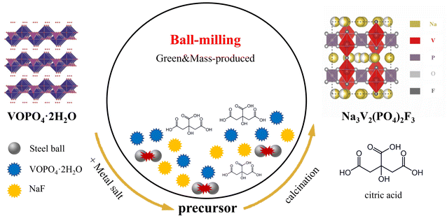
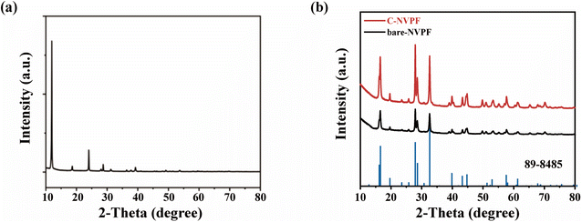
Fig. 1 vividly shows the schematic diagram of the carbon coating NVPF composition by a ball-milling method. For comparison, the carbon-free Na3V2(PO4)2F3 particles (denoted as bare-NVPF) were synthesized via a similar method without the introduction of carbon. Detailed synthetic procedures are described in Experimental section.VOPO4·2H2O was used as a reaction raw material, and we first characterized its structure by XRD. According to the XRD pattern in Fig. 2(a), it can be seen that the material corresponds exactly to the peaks of VOPO4·2H2O, belonging to the tetragonal crystal system, the space group is P4/n,31 and the specific crystal structure is shown in left image in Fig. 1, which has a layered structure.
Fig. 2(b) shows the XRD patterns of the bare-NVPF and C-NVPF. As can be seen from Fig. 2(b), all diffraction peaks of the two materials correspond to the P42/mnm space group, which are belonged to the tetragonal crystal system, and both the position and the strength of the peaks are very consistent with the results simulated according to the Na3V2(PO4)2F3 framework structure.32 In addition, the peaks are sharp, indicating that both of the materials have good crystallinity and no other obvious impurity phases. To further illustrate the specific structure of NVPF, left image in Fig. 1 shows a schematic diagram of the crystal structure of NVPF. As shown in this figure, NVPF has a three-dimensional framework consisting of PO4 tetrahedron and V2O8F3 bioctahedron, all oxygen atoms in V2O8F3 bioctahedral are connected to each other by PO4, and the two VO4F2 octahedra are connected by fluorine atoms to make the V2O8F3 bioctahedron. Sodium ions exist at two different storage sites (Na1 and Na2) and can transport along the a and b plane.33
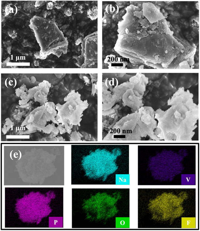
Fig. 3(a–d) presents the morphology of the as-synthesized bare-NVPF and C-NVPF powders by SEM images. Both bare-NVPF and C-NVPF exhibit similar morphology, corresponding to particles with a diameter of about 100 nm, indicating that this simple high-energy ball milling method can effectively reduce the particle size of the material. The EDX mapping distribution of various elements is shown in Fig. 3(e), which shows that the various elements (Na, V, P, O, F) present in NVPF are very evenly distributed.
Then, the composition of materials is further explored through XPS. The structural characteristics of the coated carbon can be analyzed by C (1s) photoelectron spectroscopy experiments, which are shown in Fig. 4(a). Peaks with binding energies of 284.8 eV, 285.7 eV, 287.1 eV and 289.2 eV are corresponding to C–C, C–O, C![[double bond, length as m-dash]](https://www.rsc.org/images/entities/char_e001.gif) O and O–C
O and O–C![[double bond, length as m-dash]](https://www.rsc.org/images/entities/char_e001.gif) O functional groups, respectively, and the presence of these functional groups indicates the successful carbon coating on the surface.34 Fig. 4(b) shows the electron spectrum of V 2p for two different materials, in which the peaks with combined energies of 516.9 eV and 524.1 eV corresponding to the spin photoelectron energy of V 2p3/2 and V 2p1/2, respectively, and it can be confirmed that the valence state of V is +3,35 indicating that the structure of the two materials is consistent except for the carbon coating.
O functional groups, respectively, and the presence of these functional groups indicates the successful carbon coating on the surface.34 Fig. 4(b) shows the electron spectrum of V 2p for two different materials, in which the peaks with combined energies of 516.9 eV and 524.1 eV corresponding to the spin photoelectron energy of V 2p3/2 and V 2p1/2, respectively, and it can be confirmed that the valence state of V is +3,35 indicating that the structure of the two materials is consistent except for the carbon coating.
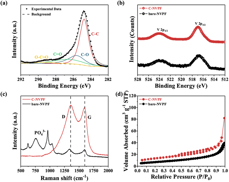 | ||
| Fig. 4 (a) Electron energy spectrum of C (1s) for C-NVPF; (b) electron energy spectrum of V (2p); (c) Raman spectra; (d) N2 adsorption and desorption curves for bare-NVPF and C-NVPF. | ||
Raman spectroscopy is also used to characterize the surface properties of the materials. As shown in Fig. 4(c), for C-NVPF, two typical peaks appear in the Raman spectra at 1350 cm−1 and 1595 cm−1, corresponding to D peaks (disordered carbon, sp3 coordination) and G peaks (graphitized carbon, sp2 coordination), respectively,36 and the ratio (ID/IG) of these two peak intensities is commonly used to assess the disorder degree of the carbon structure. However, for bare-NVPF, the intensity of D and G peaks are noticeably weaker in intensity, but more characteristic peaks of PO43− appeared at a displacement of about 700 cm−1, indicating that the carbon content in this material is less. On the contrary, there are no obvious characteristic peaks of PO43− in the C-NVPF, indicating that the carbon-coating layer is relatively dense. In addition to, the carbon content of bare-NVPF and C-NVPF tested by elemental analysis is 0.21% and 5.53% respectively, which are consistent with the Raman spectroscopy results described above.
The specific surface area of both materials is tested by the Brunauer–Emmett–Teller (BET) method and the results are shown in Fig. 4(d). It can be seen that the C-NVPF material has a small hysteresis ring in the range of 0.5–1.0, but the bare-NVPF material does not have this, which indicates that the C-NVPF material has a small amount of mesoporous structure.10 Moreover, both materials exhibit similar adsorption and desorption curves, but the specific surface area values differ greatly. Specifically, the specific surface areas of bare-NVPF and C-NVPF are 25.0 m2 g−1 and 45.4 m2 g−1, respectively. It should be noted that the larger specific surface area is conducive to the penetration of the electrolyte into the material and increases the contact area between the material and the electrolyte, thereby shortening the diffusion path of sodium ions and improving the electrochemical performance.
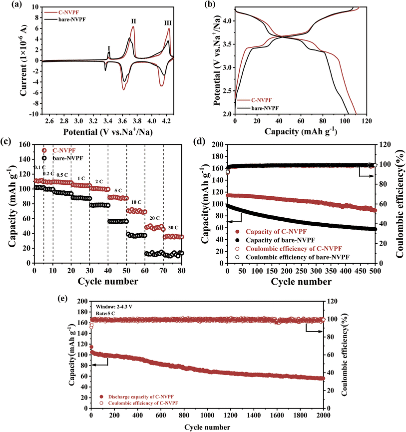
Fig. 5(a) displays the typical cyclic voltammograms (CV) of the bare-NVPF and C-NVPF electrodes at a scanning rate of 0.1 mV s−1 in the potential region of 2.5–4.3 V (vs. Na/Na+). Three pairs of symmetrical redox peaks were exhibited in the CV curves of both materials, located at 3.43/3.33 V, 3.76/3.60 V and 4.23/4.14 V, where the first two pairs of peaks correspond to a two-step intercalating/deintercalating reaction of Na+ at the Na (2) position, while the latter pair is attributed to the intercalating/deintercalating reaction of Na+ from the Na (1) position, and the result is consistent with the previous reports. In summary, the electrochemical reaction of NVPF during charging and discharging can be expressed by the following equation:26,37
| Na3V2(PO4)2F3 ⇔ Na3−xV2(PO4)2F3 + xNa+ + xe− | (1) |
| Na3−xV2(PO4)2F3 ⇔ Na2V2(PO4)2F3 + (1−x)Na+ + (1−x)e− | (2) |
| Na2V2(PO4)2F3 ⇔ NaV2(PO4)2F3 + Na+ + e− | (3) |
The Na+ storage performance of both materials is tested by constant current charge/discharge curve at a current density of 0.1C, and all experimental data were calculated based on the overall mass of the materials. As shown in Fig. 5(b), the charge–discharge curves of both materials exhibit three voltage plates that closely match to the peak positions in the CV curve. The reversible discharge capacity of the carbon-coated NVPF electrode is about 110.6 mA h g−1, which is very close to the theoretical capacity (128 mA h g−1) corresponding to the NVPF when two Na+ decoupling embeddings occur, indicating that the material makes full use of Na+ during the charging and discharging process. In sharp contrast to the C-NVPF material, the reversible discharge capacity of the bare-NVPF is only 103.59 mA h g−1, which is due to the construction of the carbon-coated layer on the surface improved the electrochemical reversibility of the material and the utilization rate of the material.
Fig. 5(c) compares the rate property of the bare-NVPF and C-NVPF electrodes at various charge–discharge current densities. As shown in this figure, for bare-NVPF, the discharge capacity decreases rapidly as the current density increases, and when the current density increases to 20C, the capacity decays to almost zero. The C-NVPF has a discharge capacity of 110.5, 109.6, 108.5, 104.6, 100.8, 87.7, 69.5 and 48.2 mA h g−1 at current densities of 0.1C, 0.2C, 0.5C, 1C, 2C, 5C, 10C and 20C (1C corresponds to the current density of 128 mA h g−1), respectively. Moreover, the electrode can still exhibit a discharge capacity of 35.1 mA h g−1 at current density up to 30 C, exhibiting a better magnification performance. Fig. 5(d) shows the cycling performance of the bare-NVPF and C-NVPF electrodes at 1C. It can be seen that the C-NVPF has a higher reversible capacity and better cycling stability, and the capacity retention is 78% after 500 cycles, while the capacity retention of the bare-NVPF electrode is only 59%. Fig. 5(e) shows the cycling performance of the C-NVPF electrode at 5C, and the capacity retention rate of the electrode is 54% after 2000 cycles. The C-NVPF electrode shows better electrochemical performance because the C-NVPF electrode can not only improve the electronic conductivity of the material, but also possible to suppress the surface reactions between the cathode material and the electrolyte to some extent.
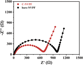
To better analyze the effect of the carbon coating on the electrochemical properties of the materials, the electrochemical impedance of the two materials in the first week of discharge are tested, as shown in Fig. 6. The semicircle in the high- to medium-frequency region of the EIS spectrum for both materials refers to the charge transfer resistance at the interface between the electrolyte and electrode, corresponding to the diffusion of sodium ions. The data after fitting according to the equivalent circuit is shown in Table 1, and the C-NVPF has a smaller charge transfer resistance, indicating that the carbon coating can not only improve the conductivity but also the charge transfer reaction of the composite electrode.
| Electrodes | Rct (Ω) |
|---|---|
| Bare-NVPF | 979.5 |
| C-NVPF | 588.9 |
4. Discussion
In summary, we have reported a facile ball-milling method to synthesize carbon coated Na3V2(PO4)2F3 with greatly improved electrochemical performances. Due to the role of the carbon-coating layer, the electronic conductivity of the material is improved, thereby improving the electrochemical properties of the material to a certain extent. It has a reversible capacity of 110.6 mA h g−1 at 0.1C, and still has a reversible capacity of 35.1 mA h g−1 at a rate of 30C. Besides, the capacity retention after 500 cycles at 1C is 78%, and the capacity retention after 2000 cycles at 5C is 54%. The improved electrochemical properties of the C-NVPF originate from its highly conductive and carbon layer, which not only suppress the aggregation of NVPF nanoparticles but also accommodate the structural stress of the material during charging and discharging. Therefore, the ball-milling method combined with the carbon reported in this work may provide a facile and effective approach to enhance the applicability and the electrochemical performance of Na-storable materials for large-scale Na-ion batteries.Author contributions
Conducted all experiments, Jiexin Zhang; designed the experiments and wrote the manuscript, Jiexin Zhang and Congrui Zhang. All authors discussed continuously and contributed to the writing of the manuscript. All authors have read and agreed to the published version of the manuscript.Conflicts of interest
There are no conflicts to declare.Acknowledgements
This research was funded by the Beijing Nova Program, grant number Z211100002121086.References
- N. Yabuuchi and K. Kubota, Research Development on Sodium-Ion Batteries, Chem. Rev., 2014, 114(23), 11636–11682 CrossRef CAS PubMed.
- M. D. Slater and D. Kim, Sodium-ion batteries, Adv. Funct. Mater., 2013, 23(8), 947–958 CrossRef CAS.
- H. Pan and Y.-S. Hu, Room-temperature stationary sodium-ion batteries for large-scale electric energy storage, Energy Environ. Sci., 2013, 6(8), 2338–2360 RSC.
- D. Yuan and X. Liang, A honeycomb-layered Na3Ni2SbO6: a high-rate and cycle-stable cathode for sodium-ion batteries, Adv. Mater., 2014, 26(36), 6301–6306 CrossRef CAS PubMed.
- Y. Cao and L. Xiao, Reversible Sodium Ion Insertion in Single Crystalline Manganese Oxide Nanowires with Long Cycle Life, Adv. Mater., 2011, 23(28), 3155–3160 CrossRef CAS PubMed.
- Y. Wang and X. Yu, A zero-strain layered metal oxide as the negative electrode for long-life sodium-ion batteries, Nat. Commun., 2013, 4, 2365 CrossRef PubMed.
- N. Yabuuchi and M. Kajiyama, P2-type Nax[Fe1/2Mn1/2]O2 made from earth-abundant elements for rechargeable Na batteries, Nat. Mater., 2012, 11(6), 512–517 CrossRef CAS PubMed.
- D. Kim and S.-H. Kang, Enabling Sodium Batteries Using Lithium-Substituted Sodium Layered Transition Metal Oxide Cathodes, Adv. Energy Mater., 2011, 1(3), 333–336 CrossRef CAS.
- J. Billaud and R. J. Clément, β-NaMnO2: A High-Performance Cathode for Sodium-Ion Batteries, J. Am. Chem. Soc., 2014, 136(49), 17243–17248 CrossRef CAS PubMed.
- Y. Fang and L. Xiao, Mesoporous Amorphous FePO4 Nanospheres as High-Performance Cathode Material for Sodium-Ion Batteries, Nano Lett., 2014, 14(6), 3539–3543 CrossRef CAS PubMed.
- Z. Jian and C. Yuan, Atomic Structure and Kinetics of NASICON NaxV2(PO4)3 Cathode for Sodium-Ion Batteries, Adv. Funct. Mater., 2014, 24(27), 4265–4272 CrossRef CAS.
- Y. Fang and L. Xiao, Hierarchical Carbon Framework Wrapped Na3V2(PO4)3 as a Superior High-Rate and Extended Lifespan Cathode for Sodium-Ion Batteries, Adv. Mater., 2015, 27(39), 5895–5900 CrossRef CAS PubMed.
- C. Zhu and K. Song, Carbon-Coated Na3V2(PO4)3 Embedded in Porous Carbon Matrix: An Ultrafast Na-Storage Cathode with the Potential of Outperforming Li Cathodes, Nano Lett., 2014, 14(4), 2175–2180 CrossRef CAS PubMed.
- S.-M. Oh and S.-T. Myung, Reversible NaFePO4 electrode for sodium secondary batteries, Electrochem. Commun., 2012, 22, 149–152 CrossRef CAS.
- Y. Fang and J. Zhang, Phosphate Framework Electrode Materials for Sodium Ion Batteries, Adv. Sci., 2017, 4, 1600392 CrossRef PubMed.
- J. F. Qian and M. Zhou, Nanosized Na4Fe(CN)6/C Composite as a Low-Cost and High-Rate Cathode Material for Sodium-Ion Batteries, Adv. Energy Mater., 2012, 2(4), 410–414 CrossRef CAS.
- L. Wang and Y. Lu, A superior low-cost cathode for a Na-ion battery, Angew. Chem., Int. Ed., 2013, 52(7), 1964–1967 CrossRef CAS PubMed.
- W. Song and X. Cao, Investigation of the sodium ion pathway and cathode behavior in Na3V2(PO4)2F3 combined via a first principles calculation, Langmuir, 2014, 30(41), 12438–12446 CrossRef CAS PubMed.
- C. Zhu and C. Wu, A high power-high energy Na3V2(PO4)2F3 sodium cathode: Investigation of transport parameters, rational design and realization, Chem. Mater., 2017, 29(12), 5207–5215 CrossRef CAS.
- T. Jiang and Y. J. Wei, Preparation and electrochemical studies of Li3V2(PO4)3/Cu composite cathode material for lithium ion batteries, J. Alloys Compd., 2009, 488(1), L26–L29 CrossRef CAS.
- R. Gover, A. Bryan and P. Burns, The electrochemical insertion properties of sodium vanadium fluorophosphate, Na3V2(PO4)2F3, Solid State Ionics, 2006, 177(17–18), 1495–1500 CrossRef CAS.
- J. Barker and R. K. B. Gover, Hybrid-Ion A lithium-ion cell based on a sodium insertion material, Electrochem. Solid-State Lett., 2006, 9(4), A190–A192 CrossRef CAS.
- R. A. Shakoor and D.-H. Seo, A combined first principles and experimental study on Na3V2(PO4)2F3 for rechargeable Na batteries, J. Mater. Chem., 2012, 22(38), 20535–20541 RSC.
- D. D. Yuan and Y. X. Wang, Improved electrochemical performance of Fe-substituted NaNi0.5Mn0.5O2 cathode materials for sodium-ion batteries, ACS Appl. Mater. Interfaces, 2015, 7(16), 8585–8591 CrossRef CAS PubMed.
- Q. Liu and D. Wang, Carbon-coated Na3V2(PO4)2F3 nanoparticles embedded in a mesoporous carbon matrix as a potential cathode material for sodium-ion batteries with superior rate capability and long-term cycle life, J. Mater. Chem. A, 2015, 3(43), 21478–21485 RSC.
- C. Shen and H. Long, Na3V2(PO4)2F3@C dispersed within carbon nanotube frameworks as a high tap density cathode for high-performance sodium-ion batteries, J. Mater. Chem. A, 2018, 6(14), 6007–6014 RSC.
- L. Li and Y. Xu, High capacity-favorable tap density cathode material based on three- dimensional carbonous framework supported Na3V2(PO4)2F3 nanoparticles, Chem. Eng. J., 2018, 331, 712–719 CrossRef CAS.
- Q. Liu and X. Meng, Core/double-shell structured Na3V2(PO4)2F3@C nanocomposite as the high power and long lifespan cathode for sodium-ion batteries, ACS Appl. Mater. Interfaces, 2016, 8(46), 31709–31715 CrossRef CAS PubMed.
- T. Broux and F. Fauth, High rate performance for carbon-coated Na3V2(PO4)2F3 in Na-ion batteries, Small Methods, 2018, 3(4), 1800215 CrossRef.
- L. H. B. Nguyen and T. Broux, Stability in water and electrochemical properties of the Na3V2(PO4)2F3-Na3(VO)2(PO4)2F solid solution, Energy Storage Mater., 2019, 20, 324–334 CrossRef.
- Y. Fang and Q. Liu, A fully sodiated NaVOPO4 with layered structure for high-voltage and long-lifespan sodium-ion batteries, Chem, 2018, 4(5), 1167–1180 CAS.
- W. Song and X. Ji, Mechanistic investigation of ion migration in Na3V2(PO4)2F3 hybrid- ion batteries, Phys. Chem. Chem. Phys., 2015, 17(1), 159–165 RSC.
- Z. Liu and Y.-Y. Hu, Local structure and dynamics in the Na ion battery positive electrode material Na3V2(PO4)2F3, Chem. Mater., 2014, 26(8), 2513–2521 CrossRef CAS.
- R. Berthelot and D. Carlier, Electrochemical investigation of the P2-NaxCoO2 phase diagram, Nat. Mater., 2011, 10(1), 74–80 CrossRef CAS PubMed.
- G. Hu and P. Chen, Synthesis and electrochemical properties of xLiFePO4·(1−x)Na3V2(PO4)2F3/C composite for lithium-ion batteries, J. Alloys Compd., 2017, 696, 177–184 CrossRef CAS.
- Y. Cai and X. Cao, Caging Na3V2(PO4)2F3 microcubes in cross-linked graphene enabling ultrafast sodium storage and long-term cycling, Adv. Sci., 2018, 5(9), 1800680 CrossRef PubMed.
- J. Zhao and Y. Gao, High rate capability and enhanced cyclability of Na3V2(PO4)2F3 cathode by in situ coating of carbon nanofibers for sodium-ion battery applications, Chemistry, 2018, 24(12), 2913–2919 CrossRef CAS PubMed.
| This journal is © The Royal Society of Chemistry 2024 |

