 Open Access Article
In situ fluoro-oxygen codoped graphene layer for high-performance lithium metal anode†
Yue Lia,
Jia Xiang*b,
Yahao Li *a,
Lulu Zhanga,
Huachao Taoc and
Xuelin Yang*abc
aHubei Provincial Collaborative Innovation Center for New Energy Microgrid, College of Electrical Engineering & New Energy, China Three Gorges University, Yichang, 443002, Hubei, China. E-mail: 408768011@qq.com; liyahao66@126.com; xlyang@ctgu.edu.cn
bAnalysis and Testing Center, China Three Gorges University, Yichang, 443002, China
cCollege of Materials and Chemical Engineering, China Three Gorges University, Yichang, 443002, Hubei, China
First published on 5th April 2024
Abstract
Because traditional lithium-ion batteries have been unable to meet the energy density requirements of various emerging fields, lithium–metal batteries (LMBs), known for their high energy density, are considered promising next-generation energy storage batteries. However, a series of problems, including low coulombic efficiency and low safety caused by dendrites, limit the application of lithium metal batteries. Herein, fluoro-oxygen codoped graphene (FGO) was used to modify the copper current collector (FGO@Cu). FGO-coated current collector provides more even nucleation sites to reduce the local effective current density. FGO is partly reduced during cycling and helps form stable LiF-rich SEI. Moreover, graphene's oxygen and fluorine functional groups reconstruct the current density distribution, promoting uniform lithium plating. The FGO@Cu current collector demonstrates superior properties than commercial Cu foil. The FGO@Cu delivers a 97% high CE for over 250 cycles at 1 mA cm−2. The FGO@Cu symmetrical battery cycled at 1 mA cm−2 for over 650 h. LiFePO4 fuel cell with a lithium-plated FGO@Cu collector as an anode exhibits superior cycling stability.
1. Introduction
As the usage of electronic devices and electric vehicles has exponentially increased in modern life, the safety and energy density requirement for secondary batteries keeps increasing. Lithium metal battery (LMB) is promising as a power supplier for these electrical appliances thanks to lithium metal anode's unmatched theoretical capacity and redox potential.1,2 However, unwanted Li dendrite growth ascribed to a high diffusion barrier of Li, inhomogeneous electrical field, and uneven Li-ion flux would break SEI and pierce the membrane, causing cell failure and even thermal runaway, leading to serious safety hazards.3,4Various strategies, such as building artificial SEI layers with high mechanical modulus, good electrical insulation, and rapid Li-ion diffusion rate;5,6 optimizing electrolytes, including introducing electrolyte additives and using high-concentration lithium salt electrolytes;7,8 constructing 3D hosts with unique surface chemistry and interconnecting structures;9,10 regulating surface lithiophilicity by introducing lithiophilic nucleation sites, have been employed to alleviate the growth of lithium dendrites.11,12 Among these, regulating surface lithiophilicity can control Li+ flux during plating, triggering uniform Li deposition and thus alleviating lithium dendrite growth.13 Moreover, regulating surface lithiophilicity can be carried out with other modification strategies,14 synergistically solving the problem of Li anodes. Recently, the ‘anode-free’ anode for LMB attracted much attention as it used only Cu current collector as the ‘anode’ to assemble an LMB, and the real Li anode will form during cycling.15,16 With this structure, the volume of the battery can be largely reduced. However, the Li nucleation barrier on the Cu surface is relatively high, hindering the uniform Li deposition.17,18 Thus, the surface lithiophilicity of the Cu current collector for the anode-free LMB also needs to be regulated.
A commonly used method to regulate surface lithiophilicity is introducing evenly distributed lithiophilic sites.19 Lithiophilic materials such as alloys, ion-conducting frameworks, polymers, and carbon materials have been employed.20,21 Graphene-based materials are commonly utilized carbon materials for lithiophilicity optimization. Previous investigations showed that graphene oxide (GO) is lithiophilic, which can guide the uniform deposition of Li during cycling.22,23 GO can be easily anchored on the Cu current collector surface by a redox reaction between GO and Cu, simplifying the fabrication process.24 Moreover, studies show that fluorinated graphene can also improve the electrochemical performance of the anode.25,26 On the one hand, the fluorine-doped graphene provided high lithiophilicity, which regulated the Li flux and averaged the local current density. On the other hand, the reaction between the fluorine functional group and the electrolyte in situ generated a stable LiF-rich SEI, which has an excellent Li-ion diffusion rate and can suppress lithium dendrite. However, graphene-based materials are mostly fabricated via the modified Hummers' method or CVD, which uses high-risk procedures or has a high demand for the instrument, thus hindering the large-scale application of graphene-based materials.27,28
Here, we propose a straightforward and eco-friendly process for producing fluorine-doped graphene oxide (FGO) and utilize the redox reaction between FGO and Cu to fabricate a lithiophilic layer on the current collector for Li metal battery. The resulting FGO@Cu anode exhibited excellent cycle performance and coulombic efficiency. The optimized electrode can operate for over 250 cycles at 1 mA cm−2 and 1 mA h cm−2. The full cells with commercial LiFePO4 (LFP) electrodes further show significantly enhanced cycling stability. The mechanism for performance enhancement is also investigated. Our work provides a simple and environmentally benign way for surface lithiophilicity regulation.
2. Experimental section
2.1 Synthesis of fluorinated graphene
The synthesis of fluorinated graphene was carried out in a homemade two-electrode electrolyzer with a DC power supply. Graphite sheets (4 × 8 cm JingLong TeTan Beijing) were used as the cathode and anode. NaF (0.2 M) and H2SO4 (0.1 M) were used as the electrochemical exfoliation electrolytes. A 7 V potential bias was added for 10 h to conduct the exfoliation. After the exfoliation, the expended graphite was washed with 2 L deionized water (DI water), re-dispersed in 600 mL DI water, and ultrasonicated for 2 h. Then, the sample was centrifuged at 3000 rpm to separate fluorinated graphene and graphite particles. The upper solution was extracted and centrifuged at 9000 rpm to collect fluorinated graphene.2.2 Current collector modification
The Cu foil was cut into small discs (1.539 cm2) and then washed with DI water, 0.5 M NaOH solution, DI water, 0.5 M HCl solution, and DI water in a sequence. After cleaning, the copper discs were sliced and soaked in the graphene dispersion (for 1, 3, 6, and 12 h), rinsed, and dried at 50 °C. The FGO@Cu current collector was then obtained.2.3 Material characterizations
Scanning electron microscopy (SEM, JEOL-7500) and high-resolution transmission electron microscopy (HRTEM, JEM-F200, JEOL) were used to reveal the morphology of the samples. The characteristic functional groups were analyzed using Fourier transform infrared spectroscopy (FT-IR, Frontier NIR, and PE). The elemental compositions were analyzed by X-ray photoelectron spectroscopy (XPS, Escalab 250Xi, Thermo Scientific). The chemical structures of GO and FGO were revealed by Raman spectroscopy (DXR2, Thermo Scientific).2.4 Electrochemical measurements
All electrochemical tests used coin-type cells (CR2025) with Celgard 2400 as the separator. Note that 1.0 M LiTFSI-DOL/DME with 2 wt% LiNO3 was used as the electrolyte. The CE of the half cell was tested using Cu as the cathode and Li as the anode. For symmetric cells, 3 mA h cm−2 Li was deposited at 0.5 mA cm−2 on all testing samples in advance. For LFP full cells, the commercial LFP powder, acetylene black, and PVDF were mixed with a mass ratio of 8![[thin space (1/6-em)]](https://www.rsc.org/images/entities/char_2009.gif) :
:![[thin space (1/6-em)]](https://www.rsc.org/images/entities/char_2009.gif) 1
1![[thin space (1/6-em)]](https://www.rsc.org/images/entities/char_2009.gif) :
:![[thin space (1/6-em)]](https://www.rsc.org/images/entities/char_2009.gif) 1, then cast on an Al foil and dried overnight at 110 °C to obtain the LFP cathode. The mass loading of LFP was 1.2 mg cm−2. Li-plated current collectors were used as the anode, and 1.0 M LiPF6 in 1
1, then cast on an Al foil and dried overnight at 110 °C to obtain the LFP cathode. The mass loading of LFP was 1.2 mg cm−2. Li-plated current collectors were used as the anode, and 1.0 M LiPF6 in 1![[thin space (1/6-em)]](https://www.rsc.org/images/entities/char_2009.gif) :
:![[thin space (1/6-em)]](https://www.rsc.org/images/entities/char_2009.gif) 1 EC
1 EC![[thin space (1/6-em)]](https://www.rsc.org/images/entities/char_2009.gif) :
:![[thin space (1/6-em)]](https://www.rsc.org/images/entities/char_2009.gif) DMC was used as the electrolyte. The cycle tests of the full cells were carried out at 0.5C (1C = 180 mA g−1) at 2.0–4.2 V.
DMC was used as the electrolyte. The cycle tests of the full cells were carried out at 0.5C (1C = 180 mA g−1) at 2.0–4.2 V.
2.5 Theoretical simulations
All calculations were based on DFT as implemented in the VASP with the exchange–correlation function of GGA of the PBE method. A grid of 2 × 3 × 1 Monkhorst–Pack k-points was used. A vacuum layer of 15 Å was adopted to avoid interactions between the periodic slabs. The energy cutoff was set to be 520 eV. The convergence criterion for the energy and maximum force for the optimization were set to 10−5 eV and 0.05 eV Å−1, respectively. The adsorption ability and stability of the molecules on the surface were evaluated by comparing the adsorption energy, and the adsorption energy, defined as:| Eads = Eadsorb/surf − Esurf – Eadsorb |
3. Results and discussion
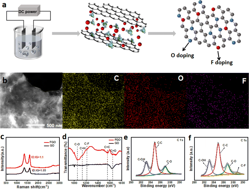
We used the simple graphite electrochemical exfoliation in NaF and H2SO4 mixture electrolytes to realize the one-step fabrication of fluorine-doped graphene oxide (Fig. 1a). NaF was used as the fluorine source, and SO42− is a typical exfoliating agent for graphene preparation. The typical SEM images of FGO nanosheets are shown in Fig. S1;† the wrinkled sheet structure of graphene can be observed. Moreover, most of the FGO obtained have few layers. HAADF-STEM results and corresponding elemental mappings of the FGO nanosheet are shown in Fig. 1b. C, O, and F are uniformly distributed in the sample, suggesting the homogeneous distribution of the introduced fluorine (Fig. 1b). For comparison, a GO sample was also produced via electrochemical exfoliation using only H2SO4 as the electrolyte. The typical SEM images of GO are shown in Fig. S2.† A structure similar to FGO can be observed for the GO sample, suggesting that F-doping has little effect on the structure of GO. In the Raman spectra (Fig. 1c), D, G, and 2D bands at about 1328, 1583, and 2640 cm−1 can be observed for both samples, respectively. The few-layer structure of GO can thus be confirmed.29 The ID/IG ratio of FGO is higher than that of GO, as the F-doping increased the disorder of GO.30 Fig. 1d shows the FTIR spectra of FGO and GO. The synthesized FGO film comprises various oxygen functional groups attributed to the C–H stretching vibrations at 1160 cm−1, C![[double bond, length as m-dash]](https://www.rsc.org/images/entities/char_e001.gif) C at 1573 cm−1, C
C at 1573 cm−1, C![[double bond, length as m-dash]](https://www.rsc.org/images/entities/char_e001.gif) O at 1705 cm−1, and C–O at 1052 cm−1. The 1210 cm−1 peak ascribed to the vibration of the C–F bond was observed only in the spectrum of FGO.30–32 Fig. 1e shows the characteristic deconvoluted C1s spectra of GO, in that the peaks for the C–C bond, C–O bond, and C–OH bond can be observed.30,33 For F–GO (Fig. 1f), in addition to the peaks observed in GO, a new peak at 288.8 eV corresponding to the C–F bond can be observed. These results mutually prove the successful doping of F into GO via the simple one-step electrochemical exfoliation method.
O at 1705 cm−1, and C–O at 1052 cm−1. The 1210 cm−1 peak ascribed to the vibration of the C–F bond was observed only in the spectrum of FGO.30–32 Fig. 1e shows the characteristic deconvoluted C1s spectra of GO, in that the peaks for the C–C bond, C–O bond, and C–OH bond can be observed.30,33 For F–GO (Fig. 1f), in addition to the peaks observed in GO, a new peak at 288.8 eV corresponding to the C–F bond can be observed. These results mutually prove the successful doping of F into GO via the simple one-step electrochemical exfoliation method.
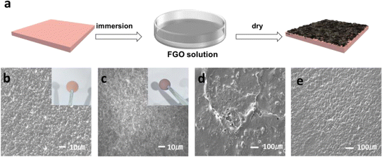
The preparation procedure of the FGO@Cu electrode is shown in Fig. 2a. FGO is anchored on the Cu surface via the room-temperature redox reaction between FGO and Cu. The digital photos of FGO/Cu and Cu are shown in the inset figures of Fig. 2b and c, where the color of FGO@Cu is darker than that of Cu. The SEM image of Cu (Fig. 2b) displays a rough surface with many protrusions. In contrast, the FGO/Cu (Fig. 2c) exhibits a smooth and flat surface, suggesting that FGO coverage can smoothen the Cu surface concavity. The SEM of FGO@Cu and pure Cu after Li plating (1 mA h cm−2) are shown in Fig. 2d and e. Li–Cu exhibits an uneven surface with randomly distributed pores and protrusions, leading to the formation of Li dendrites after cycling. However, Li-FGO@Cu demonstrated an even and flat surface morphology, facilitating dendrite-free electrode cycling. High magnification details are shown in Fig. S3.†
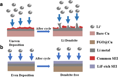
A schematic of the Li plating behavior on Cu foil and FGO@Cu is provided in Fig. 3. Due to the uneven surface of Cu foil, Li metal will preferentially deposit on the protrusion, leading to dendrite growth (Fig. 3a). Sharp dendrites will pierce the membrane and cause short-circuit and thermal runaway. Moreover, the dendrite is preferentially dissolved at the root and forms “dead Li”, which greatly reduces the coulombic efficiency of the battery.34–37 However, with the help of uniformly distributed lithiophilic FGO, the local current density can be even, and the Li nucleation barrier will be reduced, leading to even Li deposition (Fig. 3b). Moreover, the partially reduced graphene oxide can increase the conductivity of the collector. These results suggest FGO@Cu's potential for practical applications.15,26,38
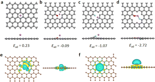
The corresponding DFT calculations are conducted to reveal the influence of fluoro-oxygen codoping on the lithiophilicity of graphene. Here, we calculated the Li binding energies of four types of graphenes: pure graphene, oxygen-doped graphene, fluorine-doped graphene, and fluoro-oxygen codoped graphene, and the corresponding binding energies are 0.23, −0.09, −1.07, and −2.72 eV, respectively (Fig. 4a–d). Among them, fluoro-oxygen codoped graphene demonstrated the highest adsorption energy, which indicates that the codoping of fluorine and oxygen has a synergistic effect on the adsorption of lithium ions. We also calculated another configuration of fluoro-oxygen codoping graphene, and the results show that the adsorption energy is still greater than that of graphenes with only oxygen or fluorine dopings (Fig. S4†). To understand the role of the fluoro-oxygen codoping in the lithium plating/stripping process, we calculated the charge distribution of fluoro-oxygen codoped graphene. The obtained differential charge density diagrams are shown in Fig. 4e and f, where the yellow region is the charge gain region, and the blue region is the charge lost region. Compared with pure graphene, the charge gain region on the surface of the doped graphene is conducive to the adsorption of lithium ions, and the dynamic diffusion of the charge gain region after adsorption can guide lithium ions to uniform deposits in the direction horizontal to the electrode surface, and ease the growth of dendrites.39–41
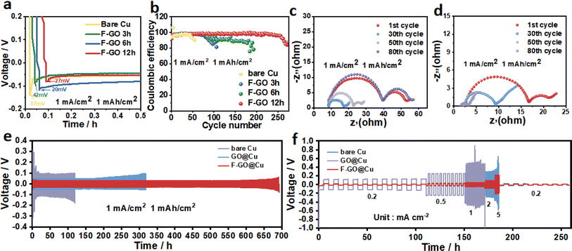
The electrochemical performances of half cells with Cu foil, GO@Cu, and FGO@Cu are displayed in Fig. 5. Compared to the bare Cu current collector (with a nucleation overpotential of 87 mV), the FGO-coated Cu electrodes exhibited lower nucleation overpotential (Fig. 5a), demonstrating that the FGO layer can effectively reduce the energy barrier of Li nucleation. Moreover, as the immersion duration increased from 3 to 12 h, the nucleation overpotential further decreased to 20 mV from 42 mV. However, extending the immersion duration to 16 h increases the nucleation overpotential to 58 mV (Fig. S5a†), ascribed to the overoxidation of Cu. The overpotential of GO@Cu and FGO@Cu half batteries with an immersion duration of 12 h are then compared. Evidently, FGO with stronger lipophilicity has a more significant effect on reducing the nucleation overpotential of lithium (Fig. S5b†).
Moreover, the CE of the modified electrodes increases with the extension of immersion duration. Bare Cu exhibited a CE of 95% for the initial 45 cycles and then fluctuated (Fig. 4b). GO@Cu maintained a CE of 98% for 90 cycles, which is more stable than that of bare Cu (Fig. S6†). The FGO@Cu shows the best performance for maintaining a CE of 98% for over 250 cycles. Moreover, EIS tests were performed to investigate the electrochemical reaction kinetics. FGO@Cu cell's interface resistance (Rf) is smaller than that of bare Cu at the initial cycle and stable after the 30th cycle. The Rf for bare Cu significantly increased after 30 cycles (Fig. 5c and d). The results suggest that the lithiophilic FGO coating can reduce the Li nucleation barrier and facilitate electron transport on the current collector.
The cycle stability of FGO@Cu, GO@Cu, and bare Cu were investigated by the galvanostatic test. All symmetrical cells comprised two identical electrodes, on which 2 mA h cm−2 Li was deposited at 0.5 mA cm−2. Fig. 4e shows the curves obtained at 1 mA cm−2 and 1 mA h cm−2. FGO@Cu symmetrical cell exhibited a lower voltage hysteresis than GO@Cu and bare Cu. The operation duration of the FGO@Cu symmetrical cell was considerably longer, reaching 690 h, proving the superior cycle stability of the FGO@Cu electrode. Results of the symmetrical cells tested at higher current densities are shown in Fig. S7,† demonstrating that the FGO@Cu symmetrical cell still offers better cyclic stability at 2 mA cm−2 and 1 mA h cm−2. The symmetrical cells were tested at 0.2 mA cm−2 from 1 to 10 cycles, 0.5 mA cm−2 from 10 to 20 cycles, 1 mA cm−2 from 21 to 30 cycles, 2 mA cm−2 from 31 to 40 cycles, and 0.2 mA cm−2 from 41 to 50 cycles to reveal their rate performances. The voltage hysteresis of F-GO@Cu then increases from 11 to 25 mV as the current density increases from 0.2 to 5 mA cm−2, and then reduces to 12 mV and remains stable when the current density returns to 0.2 mA cm−2. The GO@Cu symmetric cell shows a prominent disorder when the current density increases from 0.2 to 0.5 mA cm−2. However, the bare Cu succumbed to severe voltage fluctuation as the current density increased to 1 mA cm−2. We compared different Cu modification methods made for lithium metal batteries. As shown in Fig. S8,† this strategy is quite effective in improving the stability of the battery cycle.42–46
The morphology evolution of the deposited Li after further cycling illustrates the effect of FGO coating on Li plating/stripping behavior. After cycling at 1 mA cm−2 and 1 mA h cm−2 for 50 cycles, lithium whiskers and dendrites can be observed on the electrode surface of the Cu symmetrical cell (Fig. 6a). However, after 100 cycles at 1 mA cm−2 and 1 mA h cm−2, the Li deposited on the surface of the F-GO@Cu electrode is still compact and uniform without obvious Li dendrites (Fig. 6b). This distinction can be attributed to the abundant lithiophilic sites on the fluorine-rich FGO current collector that can guide the uniform deposition of Li. Moreover, the fluorine-rich electrode facilitated the formation of LiF-rich SEI with higher mechanical strength that can suppress the Li dendrite growth.
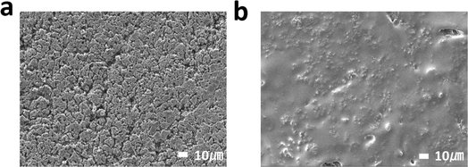 | ||
| Fig. 6 (a) SEM image of bare Cu symmetrical cell plating after 50 cycles. (b) FGO symmetrical cell plating after 100 cycles. | ||
XPS tests were performed to investigate the SEI compositions. The obtained C 1s and F 1s spectra for FGO@Cu and GO@Cu electrodes after 50 and 100 cycles in half cells are shown in Fig. 7a–d. In C 1s spectra, fitting results show that peaks for C–C bond, C–O bond, C![[double bond, length as m-dash]](https://www.rsc.org/images/entities/char_e001.gif) O bond, and C–F bond can all be observed.47,48 For FGO@Cu, the proportions of each bond remain constant. In contrast, the component proportions of the SEI of GO@Cu change after cycling, suggesting the poor stability of SEI. The poor SEI stability is responsible for the poor cycle stability of GO@Cu and the CE of GO@Cu half cell was sharply decent at about the 90th cycle (Fig. S6†). Fig. 7c and d show the F 1s spectra of FGO@Cu and GO@Cu. Peaks for LiF were constantly observed. Moreover, the proportion increased from 5.3% to 12.22% during cycling, suggesting that FGO@Cu can continuously supply F for LiF formation, reinforcing the SEI as the operation proceeded and benefiting the long-term cyclic stability of the cell. As for GO@Cu, the LiF signal vanished and the signal for SF6 appeared after cycling, suggesting the SEI's poor stability.49,50
O bond, and C–F bond can all be observed.47,48 For FGO@Cu, the proportions of each bond remain constant. In contrast, the component proportions of the SEI of GO@Cu change after cycling, suggesting the poor stability of SEI. The poor SEI stability is responsible for the poor cycle stability of GO@Cu and the CE of GO@Cu half cell was sharply decent at about the 90th cycle (Fig. S6†). Fig. 7c and d show the F 1s spectra of FGO@Cu and GO@Cu. Peaks for LiF were constantly observed. Moreover, the proportion increased from 5.3% to 12.22% during cycling, suggesting that FGO@Cu can continuously supply F for LiF formation, reinforcing the SEI as the operation proceeded and benefiting the long-term cyclic stability of the cell. As for GO@Cu, the LiF signal vanished and the signal for SF6 appeared after cycling, suggesting the SEI's poor stability.49,50
 | ||
| Fig. 7 C 1s and F 1s high-resolution spectra after 50 and 100 cycles of (a) (c) FGO@Cu and (b) (d) GO@Cu. | ||
To further explore the practical application of the FGO@Cu current collector, the FGO@Cu and bare Cu were plated with 3 mA h cm−2 of Li and used as anodes to assemble Li-LFP full cells. The fabricated full cells were denoted as Li-FGO@Cu‖LFP and Li-bare Cu‖LFP, respectively. The results (Fig. 8a and b) show that the bare Li-bare Cu‖LFP showed capacity decay after the 5th cycle. While for Li-FGO@Cu‖LFP, its capacity remained stable during the test. In addition, the Li-FGO@Cu‖LFP full cell exhibits a superior rate performance and delivers a reversible capacity of 172.3, 158.5, 140.7, and 120.3 mA h g−1 at 0.2, 0.5, 1, and 2C, respectively (Fig. 8c). Fig. 8d shows the long-term stability of Li-FGO@Cu‖LFP and Li-bare Cu‖LFP full cells. At the rate of 0.5C, the batteries with unmodified Cu collectors delivered an initial capacity of 150.9 mA h g−1 and were degraded to 21.8 mA h g−1 after 100 cycles. On the contrary, the FGO-modified full cell shows a much better capacity retention of 88.4%.
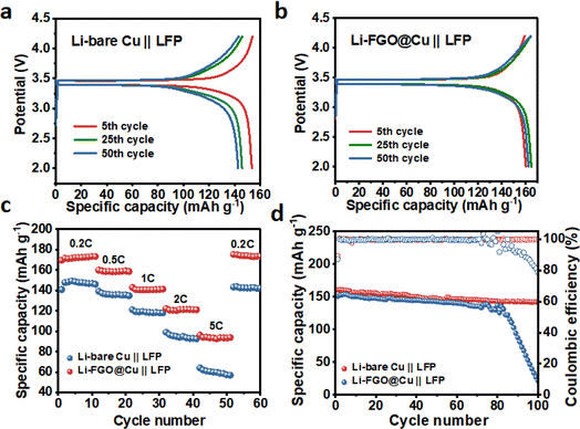 | ||
| Fig. 8 The discharge/charge voltage profiles at different cycle numbers of (a) FGO@Cu (b) bare Cu rate performance, and (c) long-term cycling (d) at 0.5C of FGO@Cu and bare Cu. | ||
4. Conclusions
We fabricated FGO@Cu anodes via a simple in situ redox reaction for LMB. Ascribing to the synergistic effect of the high lithiophilicity provided by F–O-codoping sites and the high electron conductivity offered by graphene, the FGO@Cu expressed an improved CE of 98% after 250 cycles and stable cycling for 680 h at 1 mA cm−2 in the half cell with a low-voltage hysteresis of 20 mV. DFT simulation revealed that the synergistic effect of F and O codoping can facilitate Li-ion adsorption and guide even Li deposition. This study demonstrates a feasible approach to modify the Cu foil with FGO, which is conducive to developing lithium metal batteries with high commercial potential.Conflicts of interest
There are no conflicts to declare.Acknowledgements
This work was financially supported by the National Key R&D Program of China (2022YFB3807700), the National Natural Science Foundation of China (52072217 and 22179071), the Hubei Natural Science Foundation Innovation Group Project (2022CFA020), the Major Technological Innovation Project of Hubei Science and Technology Department (2019AAA164), Joint Funds of the Hubei Natural Science Foundation Innovation and Development (2022CFD034), and Guangxi Key Laboratory of Low Carbon Energy Material (2023GXKLLCEM0101).References
- Q. Wang, B. Liu, Y. Shen, J. Wu, Z. Zhao, C. Zhong and W. Hu, Confronting the Challenges in Lithium Anodes for Lithium Metal Batteries, Adv. Sci., 2021, 8, 2101111 CrossRef CAS PubMed.
- J. Wang, B. Ge, H. Li, M. Yang, J. Wang, D. Liu, C. Fernandez, X. Chen and Q. Peng, Challenges and progresses of lithium-metal batteries, Chem. Eng. J., 2021, 420, 129739 CrossRef CAS.
- B. Wu, C. Chen, L. H. J. Raijmakers, J. Liu, D. L. Danilov, R.-A. Eichel and P. H. L. Notten, Li-growth and SEI engineering for anode-free Li-metal rechargeable batteries: A review of current advances, Energy Storage Mater., 2023, 57, 508–539 CrossRef.
- R. Zhang, X. Shen, Y.-T. Zhang, X.-L. Zhong, H.-T. Ju, T.-X. Huang, X. Chen, J.-D. Zhang and J.-Q. Huang, Dead lithium formation in lithium metal batteries: A phase field model, J. Energy Chem., 2022, 71, 29–35 CrossRef CAS.
- L. Gan, K. Wang, Y. Liu, W. Ahmad, X. Wang, J. Chen, M. Ling, M. Sun and C. Liang, Dendrite-free Li-metal anode via a dual-function protective interphase layer for stable Li-metal pouch cell, Sustain. Mater. Technol., 2023, 36, e00585 CAS.
- X.-Q. Xu, F.-N. Jiang, S.-J. Yang, Y. Xiao, H. Liu, F. Liu, L. Liu and X.-B. Cheng, Dual-layer vermiculite nanosheet based hybrid film to suppress dendrite growth in lithium metal batteries, J. Energy Chem., 2022, 69, 205–210 CrossRef CAS.
- S. Wang, Z. Xue, F. Chu, Z. Guan and J. Lei, Moderately concentrated electrolyte enabling high-performance lithium metal batteries with a wide working temperature range, J. Energy Chem., 2023, 79, 201–210 CrossRef CAS.
- P. Wen, Y. Liu, J. Mao, X. Liu, W. Li, Y. Ren, Y. Zhou, F. Shao, M. Chen, J. Lin and X. Lin, Tuning desolvation kinetics of in-situ weakly solvating polyacetal electrolytes for dendrite-free lithium metal batteries, J. Energy Chem., 2023, 79, 340–347 CrossRef CAS.
- X. Yan, F. Ye, Y. Zhang, L. Lin, B. Sa, F. Liu, J. Li, L. Wang, J. Lin, Q. Xie and D.-L. Peng, Understanding the anchoring effect on Li plating with Indium Tin oxide layer functionalized hosts for Li metal anodes, Chem. Eng. J., 2022, 440, 135827 CrossRef CAS.
- T. Jiang, L. Sun, Y. Zhang, X. Zhang, H. Lin, K. Rui and J. Zhu, Lithiophilic interface dynamic engineering to inhibit Li dendrite growth for intrinsically safe Li-metal batteries, Chem. Eng. J., 2023, 464, 142555 CrossRef CAS.
- Y. Li, Y. Li, L. Zhang, H. Tao, Q. Li, J. Zhang and X. Y. Lithiophilicity, The key to efficient lithium metal anodes for lithium batteries, J. Energy Chem., 2023, 77, 123–136 CrossRef CAS.
- P. Shi, T. Li, R. Zhang, X. Shen, X. B. Cheng, R. Xu, J. Q. Huang, X. R. Chen, H. Liu and Q. Zhang, Lithiophilic LiC(6) Layers on Carbon Hosts Enabling Stable Li Metal Anode in Working Batteries, Adv. Mater., 2019, 31(8), e1807131 CrossRef PubMed.
- Y. Liu, J. Sun, X. Hu, Y. Li, H. Du, K. Wang, Z. Du, X. Gong, W. Ai and W. Huang, Lithiophilic sites dependency of lithium deposition in Li metal host anodes, Nano Energy, 2022, 94, 106883 CrossRef CAS.
- Z. Yang, Y. Dang, P. Zhai, Y. Wei, Q. Chen, J. Zuo, X. Gu, Y. Yao, X. Wang, F. Zhao, J. Wang, S. Yang, P. Tang and Y. Gong, Single-Atom Reversible Lithiophilic Sites toward Stable Lithium Anodes, Adv. Energy Mater., 2022, 2103368 CrossRef CAS.
- M. Chen, L. Cheng, J. Chen, Y. Zhou, J. Liang, S. Dong, M. Chen, X. Wang and H. Wang, Facile and Scalable Modification of a Cu Current Collector toward Uniform Li Deposition of the Li Metal Anode, ACS Appl. Mater. Interfaces, 2020, 12(3), 3681–3687 CrossRef CAS PubMed.
- G. Lai, J. Jiao, C. Fang, Y. Jiang, L. Sheng, B. Xu, C. Ouyang and J. Zheng, The Mechanism of Li Deposition on the Cu Substrates in the Anode-Free Li Metal Batteries, Small, 2023, 19(3), e2205416 CrossRef PubMed.
- H. Shen, P. Tang, Q. Wei, Y. Zhang, T. Yu, H. Yang, R. Zhang, K. Tai, J. Tan, S. Bai and F. Li, Directing Highly Ordered and Dense Li Deposition to Achieve Stable Li Metal Batteries, Small, 2023, 19(24), e2206000 CrossRef PubMed.
- Y. Wang, Z. Zhao, W. Zeng, X. Liu, L. Wang, J. Zhu and B. Lu, Hierarchically porous Cu current collector with lithiophilic Cu O interphase towards high-performance lithium metal batteries, J. Energy Chem., 2021, 58, 292–299 CrossRef CAS.
- Y. Wang, Z. Zhao, W. Zeng, X. Liu, L. Wang, J. Zhu and B. Lu, Unveiling the role of lithiophilic sites denseness in regulating lithium ion deposition, J. Energy Chem., 2022, 71, 324–332 CrossRef.
- Y.-W. Song, P. Shi, B.-Q. Li, X. Chen, C.-X. Zhao, W.-J. Chen, X.-Q. Zhang, X. Chen and Q. Zhang, Covalent Organic Frameworks Construct Precise Lithiophilic Sites for Uniform Lithium Deposition, Matter, 2021, 4(1), 253–264 CrossRef CAS.
- J. Yang, C. Chen, K. Kashif, Q. Zhao, C. Xu, T. Li, Z. Fang and M. Wu, Melting lithium alloying to improve the affinity of Cu foil for ultra-thin lithium metal anode, J. Colloid Interface Sci., 2023, 630(Pt A), 901–908 CrossRef CAS PubMed.
- R. Zhang, X. R. Chen, X. Chen, X. B. Cheng, X. Q. Zhang, C. Yan and Q. Zhang, Lithiophilic Sites in Doped Graphene Guide Uniform Lithium Nucleation for Dendrite-Free Lithium Metal Anodes, Angew Chem. Int. Ed. Engl., 2017, 56(27), 7764–7768 CrossRef CAS PubMed.
- T. Ma, T. Y. Su, L. Zhang, J. W. Yang, H. B. Yao, L. L. Lu, Y. F. Liu, C. He and S. H. Yu, Scallion-Inspired Graphene Scaffold Enabled High Rate Lithium Metal Battery, Nano Lett., 2021, 21(6), 2347–2355 CrossRef CAS PubMed.
- P. Liu, Y. Wang, Q. Gu, J. Nanda, J. Watt and D. Mitlin, Dendrite-Free Potassium Metal Anodes in a Carbonate Electrolyte, Adv. Mater., 2020, 32(7), e1906735 CrossRef PubMed.
- Z. Li, X. Li, L. Zhou, Z. Xiao, S. Zhou, X. Zhang, L. Li and L. Zhi, A synergistic strategy for stable lithium metal anodes using 3D fluorine-doped graphene shuttle-implanted porous carbon networks, Nano Energy, 2018, 49, 179–185 CrossRef CAS.
- A. Jamaluddin, Y.-Y. Sin, E. Adhitama, A. Prayogi, Y.-T. Wu, J.-K. Chang and C.-Y. Su, Fluorinated graphene as a dual-functional anode to achieve dendrite-free and high-performance lithium metal batteries, Carbon, 2022, 197, 141–151 CrossRef CAS.
- A. V. Talyzin, G. Mercier, A. Klechikov, M. Hedenström, D. Johnels, D. Wei, D. Cotton, A. Opitz and E. Moons, Brodie vs Hummers graphite oxides for preparation of multi-layered materials, Carbon, 2017, 115, 430–440 CrossRef CAS.
- Y. Chi, J. Y. Chong, B. Wang, K. Li and J. Pristine, graphene membranes supported on ceramic hollow fibre prepared via a sacrificial layer assisted CVD approach, J. Membr. Sci., 2020, 595, 117479 CrossRef.
- F. Shahzad, S. A. Zaidi and C. M. Koo, Synthesis of Multifunctional Electrically Tunable Fluorine-Doped Reduced Graphene Oxide at Low Temperatures, ACS Appl. Mater. Interfaces, 2017, 9(28), 24179–24189 CrossRef CAS PubMed.
- K. Kakaei and A. Balavandi, Hierarchically porous fluorine-doped graphene nanosheets as efficient metal-free electrocatalyst for oxygen reduction in gas diffusion electrode, J. Colloid Interface Sci., 2017, 490, 819–824 CrossRef CAS PubMed.
- S. Ni, M. Zhang, C. Li, R. Gao, J. Sheng, X. Wu and G. Zhou, A 3D Framework with Li3N–Li2S Solid Electrolyte Interphase and Fast Ion Transfer Channels for a Stabilized Lithium-Metal Anode, Adv. Mater., 2022, 35, 2209028 CrossRef PubMed.
- D. Suhag, A. Kumar Sharma, S. K. Rajput, G. Saini, S. Chakrabarti and M. Mukherjee, Electrochemically synthesized highly crystalline nitrogen doped graphene nanosheets with exceptional biocompatibility, Sci. Rep., 2017, 7(1), 537 CrossRef PubMed.
- Q. Wei, S. Pei, G. Wen, K. Huang, Z. Wu, Z. Liu, W. Ma, H. M. Cheng and W. Ren, High Yield Controlled Synthesis of Nano-Graphene Oxide by Water Electrolytic Oxidation of Glassy Carbon for Metal-Free Catalysis, ACS Nano, 2019, 13(8), 9482–9490 CrossRef CAS PubMed.
- Z. Hu, Z. Li, Z. Xia, T. Jiang, G. Wang, J. Sun, P. Sun, C. Yan and L. Zhang, PECVD-derived graphene nanowall/lithium composite anodes towards highly stable lithium metal batteries, Energy Storage Mater., 2019, 22, 29–39 CrossRef.
- X. Wang, R.-q. Huang, S.-z. Niu, L. Xu, Q.-c. Zhang, A. Amini and C. Cheng, Research progress on graphene-based materials for high-performance lithium-metal batteries, Carbon, 2021, 183, 1012–1013 Search PubMed.
- Y. T. Chen, S. A. Abbas, N. Kaisar, S. H. Wu, H. A. Chen, K. M. Boopathi, M. Singh, J. Fang, C. W. Pao and C. W. Chu, Mitigating Metal Dendrite Formation in Lithium-Sulfur Batteries via Morphology-Tunable Graphene Oxide Interfaces, ACS Appl. Mater. Interfaces, 2019, 11(2), 2060–2070 CrossRef CAS PubMed.
- Z. Hou, X. Wang, N. Zhan, Z. Guo, Q. Chen, J. Zhang, T. Bian, B. Hu and Y. Zhao, Preparation of ultrathin graphene film via capillary liquid bridge for uniform lithium nucleation in anode free lithium metal battery, Energy Storage Mater., 2022, 53, 254–263 CrossRef.
- J. Yu, Y. Dang, M. Bai, J. Peng, D. Zheng, J. Zhao, L. Li and Z. Fang, Graphene-Modified 3D Copper Foam Current Collector for Dendrite-Free Lithium Deposition, Front. Chem., 2019, 7, 748 CrossRef CAS PubMed.
- W. Zhang, Q. Fan, D. Zhang, L. Liu, S. Liu, Z. Fang, W. Li, X. Li and M. Li, Dynamic charge modulate lithium uniform plating functional composite anode for dendrite-free lithium metal batteries, Nano Energy, 2022, 102, 107677 CrossRef CAS.
- H. Wang, Y. Chen, H. Yu, W. Liu, G. Kuang, L. Mei, Z. Wu, W. Wei, X. Ji, B. Qu and L. Chen, A Multifunctional Artificial Interphase with Fluorine-Doped Amorphous Carbon layer for Ultra-Stable Zn Anode, Adv. Funct. Mater., 2022, 2205600 CrossRef CAS.
- S. Xia, X. Zhang, L. Luo, Y. Pang, J. Yang, Y. Huang and S. Zheng, Highly Stable and Ultrahigh-Rate Li Metal Anode Enabled by Fluorinated Carbon Fibers, Small, 2021, 17(4), e2006002 CrossRef PubMed.
- A. A. Assegie, C.-C. Chung, M.-C. Tsai, W.-N. Su, C.-W. Chen and B.-J. Hwang, Multilayer-graphene-stabilized lithium deposition for anode-free lithium-metal batteries, Nanoscale, 2019, 11, 2710–2720 RSC.
- S. Cui, P. Zhai, W. Yang, Y. Wei, J. Xiao, L. Deng and Y. Gong, Large-Scale Modification of Commercial Copper Foil with Lithiophilic Metal Layer for Li Metal Battery, Small, 2020, 16, 1905620 CrossRef CAS PubMed.
- Z. Liang, G. Zheng, C. Liu, N. Liu, W. Li, K. Yan, H. Yao, P.-C. Hsu, S. Chu and Y. Cui, Polymer Nanofiber-Guided Uniform Lithium Deposition for Battery Electrodes, Nano Lett., 2015, 15, 2910–2916 CrossRef CAS PubMed.
- G. Zheng, S. W. Lee, Z. Liang, H.-W. Lee, K. Yan, H. Yao, H. Wang, W. Li, S. Chu and Y. Cui, Interconnected hollow carbon nanospheres for stable lithium metal anodes, Nat. Nanotechnol., 2014, 9, 618–623 CrossRef CAS PubMed.
- M. Zhu, K. Xu, D. Li, T. Xu, W. Sun, Y. Zhu and Y. Qian, Guiding Smooth Li Plating and Stripping by a Spherical Island Model for Lithium Metal Anodes, ACS Appl. Mater. Interfaces, 2020, 12, 38098–38105 CrossRef CAS PubMed.
- Y. Zhao, B. Chen, S. Xia, J. Yu, J. Yan and B. Ding, Selective nucleation and targeted deposition effect of lithium in a lithium-metal host anode, J. Mater. Chem. A, 2021, 9(9), 5381–5389 RSC.
- H. Gan, R. Wang, J. Wu, H. Chen, R. Li and H. Liu, Coupling a 3D Lithophilic Skeleton with a Fluorine-Enriched Interface to Enable Stable Lithium Metal Anode, ACS Appl. Mater. Interfaces, 2021, 13(31), 37162–37171 CrossRef CAS PubMed.
- H. P. Zhou, H. Zhang, H. M. Wang, S. Zhang, T. T. Feng, Z. Q. Xu, Z. X. Fang and M. Q. Wu, Plasma grown fluoride-rich artificial SEI for stabilizing Li metal anodes, J. Alloys Compd., 2023, 935, 168081 CrossRef CAS.
- J. Xiao, N. Xiao, K. Li, L. Zhang, J. Chang, X. Ma, H. Li, J. Bai, Q. Jiang and J. Qiu, Ultra-High Fluorine Enhanced Homogeneous Nucleation of Lithium Metal on Stepped Carbon Nanosheets with Abundant Edge Sites, Adv. Energy Mater., 2022, 2103123 CrossRef CAS.
Footnote |
| † Electronic supplementary information (ESI) available. See DOI: https://doi.org/10.1039/d4ra00333k |
| This journal is © The Royal Society of Chemistry 2024 |

