 Open Access Article
Superhydrophilic–superhydrophobic integrated system based on copper mesh for continuous and efficient oil–water separation†
Zhaohe
Huang
 *,
Zhenzhong
Wang
,
Shiqiang
Wang
,
Xiaowen
Shan
,
Shumeng
Yin
and
Bin
Tao
State Key Laboratory of Chemical Safety, SINOPEC Research Institute of Safety Engineering Co., Ltd, Qingdao, Shandong 266000, PR China. E-mail: huangzh.qday@sinopec.com
First published on 16th February 2024
Abstract
In petroleum, petrochemicals, metallurgy, and chemical industries, a significant volume of oily wastewater is unavoidably generated throughout the production processes. This not only harms the environment but also brings about diverse adverse effects on social and economic progress. In this study, copper mesh separation membranes exhibiting superhydrophobicity and superhydrophilicity/underwater superoleophobicity were fabricated through in situ oxidation, chemical vapor deposition, and other physical and chemical modification techniques. Moreover, copper meshes possessing contrasting wetting properties were incorporated into a system combining superhydrophilicity and superhydrophobicity enabling the continuous and efficient separation of mixed oil–water liquids. The separation efficiency of both the superhydrophobic and superhydrophilic membranes surpassed 99.0% and remained above 97.0% after 15 days of continuous use, showcasing the remarkable effectiveness and durability of the integrated system design. This research presents a straightforward and cost-effective design approach for the large-scale treatment of oily wastewater in industrial settings, which is expected to have extensive applications in practical production.
1 Introduction
Treatment of oily wastewater is urgently needed in various industrial sectors including petroleum refining, metallurgy, and chemical industries.1–4 In recent years, the uncontrolled release of substantial volumes of oily wastewater and frequent offshore oil spills have caused considerable economic losses and posed a severe risk to aquatic environments and human health.5–7 Among various oil–water separation techniques, membrane-based separation technology is generally regarded as one of the most promising methods, which has gained significant attention in recent years due to its affordability, small space requirement, and scalability.8–13The self-cleaning property of lotus leaves, as described by the ancient Chinese phrase “Out of the mud but not stained”, is a common feature found in superhydrophobic surfaces. The superhydrophobic property of lotus leaves arises from the synergistic effects of low surface energy wax and micro/nano hierarchical structures present on the leaf surface.14–16 Consequently, modifying porous substrates with low surface energy materials and designing rough structures have emerged as commonly employed techniques in membrane-based oil–water separation. The achieved superhydrophobic/superoleophilic surfaces could enable efficient separation of oil–water mixtures.17–21 In 2004, Jiang et al.22 first reported the use of superhydrophobic/superoleophilic porous stainless steel mesh membranes for oil–water separation. Moreover, separation membrane materials exhibiting superhydrophilic/underwater superoleophobic properties have been widely investigated for the treatment of oily wastewater.23 Feng et al.24 prepared a superhydrophilic/underwater superoleophobic separation membrane material based on photopolymerization. The separation membrane material consisting of micrometer-sized porous metal substrate and nanoscale hydrogel coating was capable of selective water–oil separation. Jin et al.25 prepared a poly(acrylic acid)-grafted poly(vinylidene fluoride) separation membrane material, which demonstrated extremely low adhesion to oil in water, making it suitable for separating crude oil and water mixtures. Additionally, the membrane exhibited excellent resistance to crude oil fouling, ensuring stable separation performance with a separation efficiency of 97.1% during long-term operation. Although many reports have focused on using porous separation membranes with special wetting properties for oil–water separation, they mainly centered on single membrane separation system.
In single separation systems, the separated liquid accumulates over time and causes a significant decline in separation efficiency when the liquid volume exceeds a certain threshold. In addition, utilizing a single separation system for continuous oil–water separation necessitates constant discharge of the separated liquid, ultimately leading to a considerable rise in energy consumption. This drawback makes it unsuitable for industrial applications. Hence, the single membrane separation systems previously reported are unsuitable for treating real oily wastewater.
Low-cost, widely available, mechanically robust, and corrosion-resistant commercial copper mesh was chose as base separation medium in this work. In order to tackle the aforementioned challenges, the copper mesh was modified via facile in situ oxidation and chemical vapor deposition techniques, exhibiting superhydrophobic/superoleophilic and superhydrophilic/underwater superoleophobic properties, respectively. Subsequently, these two membranes were integrated and assembled into a reverse T-shaped device to achieve continuous and efficient oil–water separation. In comparison to conventional single separation membrane systems, the dual-membrane integrated system developed in this study not only ensures high separation efficiency but also enables continuous and sustainable oil–water separation, providing a new approach for cost-effective and large-scale treatment of oily wastewater.
2 Experimental
2.1 Materials
Copper mesh (CM, 400 mesh) and trimethoxy(1H,1H,2H,2H-heptadecafluorodecyl)silane (>98.0%) (HF-TMS) were supplied by Shanghai Yier Metal Mesh Products Co., Ltd and TCI (Shanghai) Development Co., Ltd, respectively. Vegetable oil was obtained from local supermarket. HCl (36–38%, AR), NaOH (≥96%, AR), K2S2O8 (≥99.7%, AR), acetone (≥99.5%, AR), n-hexane (≥97%, AR) and ethanol (≥99.7%, AR) were purchased from Xilong Scientific Co., Ltd.2.2 Experimental method
![[thin space (1/6-em)]](https://www.rsc.org/images/entities/char_2009.gif) :
:![[thin space (1/6-em)]](https://www.rsc.org/images/entities/char_2009.gif) 1 to prepare the oxidizing solution. The cleaned copper mesh was immersed in 0.1 mol L−1 HCl 100 mL solution for 30 minutes to eliminate surface oxides. Subsequently, the copper mesh was immersed in the aforementioned oxidizing solution (200 mL) for 2 h at 40 °C. The reaction equation is shown below.
1 to prepare the oxidizing solution. The cleaned copper mesh was immersed in 0.1 mol L−1 HCl 100 mL solution for 30 minutes to eliminate surface oxides. Subsequently, the copper mesh was immersed in the aforementioned oxidizing solution (200 mL) for 2 h at 40 °C. The reaction equation is shown below.| Cu + 2NaOH + K2S2O8 → Cu(OH)2 + K2SO4 + Na2SO4 | (1) |
Afterwards, the copper mesh underwent alternating rinsing with 200 mL deionized water and 200 mL ethanol, followed by drying at 80 °C vacuum oven for subsequent utilization. The mass of the oxidized copper mesh was 0.95 g.
![[thin space (1/6-em)]](https://www.rsc.org/images/entities/char_2009.gif) :
:![[thin space (1/6-em)]](https://www.rsc.org/images/entities/char_2009.gif) 1. The oil–water mixture was continuously injected into the inlet of the device using a peristaltic pump at a 0.5 L min−1 flow rate. The liquids passing through the membranes on the oxidized copper mesh side and fluorinated copper mesh side were collected separately. To investigate the stability of the prepared materials, the separation experiments were conducted for 30 minutes and repeated for three times every day. The water content in the filtrate from the water-permeable membrane was determined using a Karl Fischer coulometer, while the oil content in the filtrate from the oil-permeable membrane was quantified using an infrared oil meter. Each measurement was repeated at least three times.
1. The oil–water mixture was continuously injected into the inlet of the device using a peristaltic pump at a 0.5 L min−1 flow rate. The liquids passing through the membranes on the oxidized copper mesh side and fluorinated copper mesh side were collected separately. To investigate the stability of the prepared materials, the separation experiments were conducted for 30 minutes and repeated for three times every day. The water content in the filtrate from the water-permeable membrane was determined using a Karl Fischer coulometer, while the oil content in the filtrate from the oil-permeable membrane was quantified using an infrared oil meter. Each measurement was repeated at least three times.
The separation efficiency of the oil/water mixture was calculated by equation as follows:
where ηH2O are the separation efficiency of fluorinated copper mesh, cH2O and c2 are the mass of water before and after separation.
2.3 Characterization
The surface morphology of copper mesh was captured using field emission scanning electron microscopy (FESEM, Hitachi, S-4800, Japan). Fourier transform infrared spectroscopy (FT-IR, Nicolet, Nicolet 4700, USA) was used to analyze the functional groups of membrane surfaces, while X-ray photoelectron spectroscopy (XPS, Thermo-VG Scientific, Escalab 250, USA) and X-ray diffraction (XRD, PANalytical, Netherland) were employed to characterize the chemical compositions of meshes surfaces. The water contact angles of the prepared mesh samples were measured by a goniometer (Dataphysics, Germany), and the oil contents of the studied systems was recorded using an IR petroleum determination instrument (OIL-9, Jingcheng Yiqi, China). The water contents of the studied systems were determined with a Karl Fischer coulometer (WKT-A8, Viscometer, China).3 Results and discussion
3.1 The overall research strategy in this work
The research strategy employed in this work is depicted in Fig. 1. The surface of original copper mesh is both hydrophilic (153° ± 3°) and oleophilic (0°), thus the porous copper mesh allowed the passage of both oil and water without selectivity. After oxidized by NaOH and K2S2O8, the copper mesh demonstrated in-air superhydrophilicity and underwater superoleophobicity. Pre-wetting the surface of the oxidized copper mesh with water enabled the rapid filtration of water while prevented the passage of oil. On the contrary, the fluorinated copper mesh, achieved by modifying the oxidized copper mesh with the low surface energy material HF-TMS, exhibited superhydrophobicity and superoleophilicity. As a result, oil could permeate through the mesh freely, meanwhile the passage of water was prohibited. Although a single oxidized copper mesh or fluorinated copper mesh could efficiently remove oil or water from oil–water mixtures, practical usage implied that the accumulated intercepted liquid over time and the tendency of rejection decline with the increased liquid volume would significantly compromised separation efficiency.26,27 In this context, this work proposed the assemble of an inverted T-shaped integrated system that combined a superhydrophilic oxidized copper mesh with a superhydrophobic fluorinated copper mesh. Consequently, efficient, scalable, and sustainable separation of oil–water mixtures could be achieved, surpassing the limitations of conventional single membrane separation system. In comparison to traditional single membrane separation systems, the inverted T-shaped integrated device overcomes the challenges posed by intercepted liquid hindrance and excessive liquid pressure during separation. Furthermore, this device exhibits high feasibility for large-scale applications.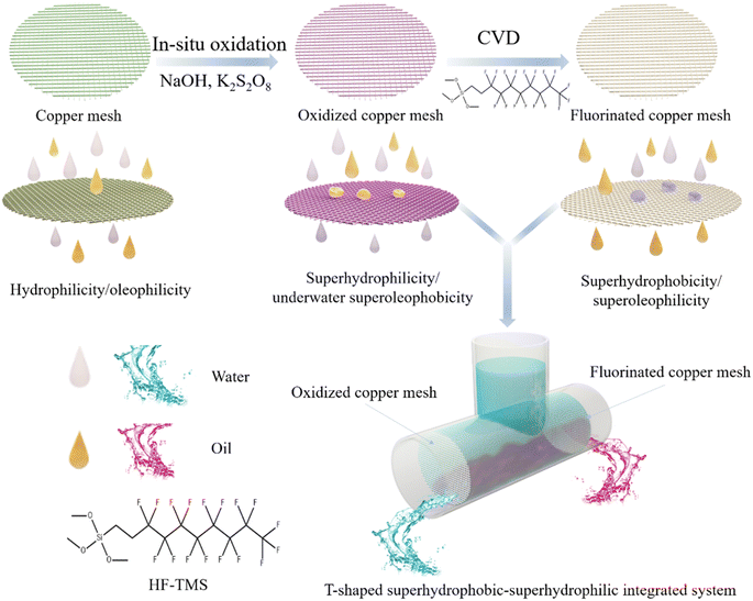 | ||
| Fig. 1 Schematic illustration for the fabrication of meshes with opposite wettability and oil–water separation via an integrated T-shaped system. | ||
3.2 Characterization of the prepared meshes
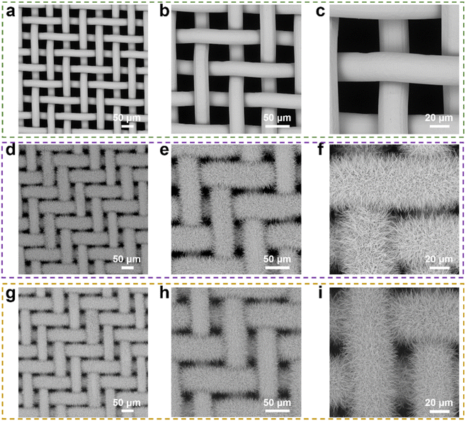
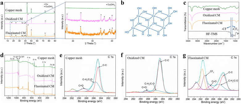
The morphologies of the untreated copper mesh, oxidized copper mesh and fluorinated copper mesh were characterized by SEM as shown in Fig. 2. Clearly, the untreated copper mesh featured a relatively flat surface without complex microstructures and had a pore diameter of approximately 38 μm. In contrast, oxidized copper mesh exhibited a rough surface covered with evenly distributed nanoneedles with a smaller pore diameter of about 10 μm. The fluorinated copper mesh exhibited a surface microstructure similar to that of the oxidized copper mesh, with uniformly distributed nanoneedles covering the surface. This observation indicated that the further modification using the low surface energy molecules (HF-TMS) did not obviously affect the microstructure of the oxidized copper mesh. In addition to the oxidation temperature of 40 °C, oxidation temperatures set at 20 °C and 60 °C were also investigated, with an oxidation duration of 2 hours for each condition. SEM images of the oxidized copper mesh revealed that at 20 °C, the nanoneedles formed on the copper mesh were sparse, failing to cover most of the original mesh pores (Fig. S1a†). However, at 60 °C, the nanoneedles evolved into nanoflower-like microstructures, which also failed to cover the original mesh pores (Fig. S1b†).XRD analysis shown in Fig. 3a indicated that the untreated copper mesh primarily consisted of Cu, whereas the oxidized copper mesh displayed diffraction peaks of Cu(OH)2 (JCPDS 03-0315).28 In the oxidation process of copper mesh, Cu initially underwent a reaction with the oxidizing solution, resulting in the formation of Cu2+ ions. Subsequently, these ions formed σ bonds with OH− to generate extended chain structures. The adjacent chains further aggregated via OH− and Cu2+ interactions, leading to the formation of a three-dimensional nanoneedle-shaped Cu(OH)2 crystal in a two-dimensional arrangement (Fig. 3b).29 The XRD pattern of the fluorinated copper mesh resembled that of the oxidized copper mesh, suggesting that the phase composition remained unchanged after modification with HF-TMS. This observation aligned well with the SEM results.
FTIR and XPS characterizations were employed to analyze the chemical compositions of the copper mesh samples. As shown in Fig. 3c, two characteristic peaks were observed on the spectra of fluorinated copper mesh and HF-TMS. The characteristic peak at 1216 cm−1 was attributed to the vibration of –CF bonds, while the peak at 1154 cm−1 was ascribed to the vibration of –CF2 bonds,30 demonstrating the successful surface modification of the fluorinated copper mesh with HF-TMS.
Furthermore, XPS spectra shown in Fig. 3d provided additional evidence regarding the surface chemical compositions of the untreated copper mesh, the oxidized copper mesh and the fluorinated copper mesh. Only the XPS spectrum of the fluorinated copper mesh exhibited a characteristic peak of F 1s at a binding energy of 688.1 eV,31 confirming the successful modification with HF-TMS. The C 1s peak observed at binding energies of 284.8 eV, 286.3 eV, and 288.9 eV corresponded to the characteristic peaks of C–C, C–Hx/C–O, and C![[double bond, length as m-dash]](https://www.rsc.org/images/entities/char_e001.gif) O, respectively.32 Although these characteristic peaks were found in all spectra (Fig. 3e–g), notable distinctions were observed between the spectrum of the fluorinated copper mesh and those of the untreated copper mesh and the oxidized copper mesh. The characteristic peak at binding energy of 290.7 eV was attributed to –CF2,33,34 which further confirmed successful modification of the copper mesh surface with HF-TMS.
O, respectively.32 Although these characteristic peaks were found in all spectra (Fig. 3e–g), notable distinctions were observed between the spectrum of the fluorinated copper mesh and those of the untreated copper mesh and the oxidized copper mesh. The characteristic peak at binding energy of 290.7 eV was attributed to –CF2,33,34 which further confirmed successful modification of the copper mesh surface with HF-TMS.
3.3 Oil–water mixtures separation experiment
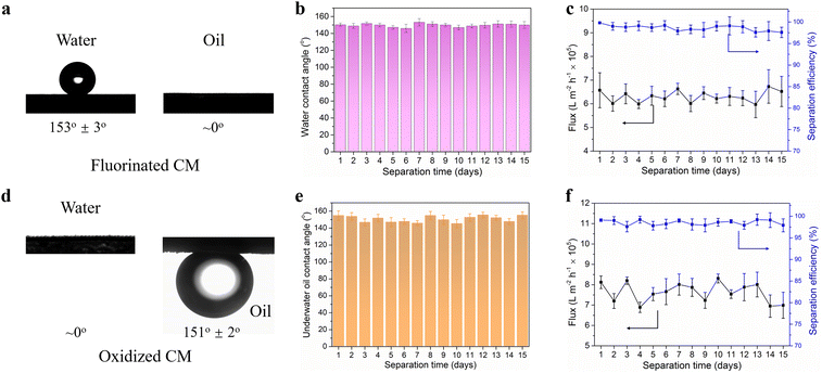
The wettability of the modified meshes and the separation performance of the T-shaped integrated oil–water separation system were investigated. Fig. 4a depicted the contact angles of water droplets and gasoline droplets on the fluorinated copper mesh. The fluorinated copper mesh demonstrated superhydrophobic/superoleophilic characteristics, displaying a contact angle of 153° ± 3° for water and approximately 0° for gasoline. The contact angles changes of the studied materials over time were investigated shown in Fig. S2.† The contact angle data reveal that the fluorinated copper mesh exhibits superhydrophobic and superoleophilic wettability characteristics, which remain essentially unchanged over time. These properties were attributed to the low surface energy coupled with the multilevel rough surface structure of the fluorinated copper mesh. Owing to the synergistic effect of these two factors, the fluorinated copper mesh exhibited superhydrophobic properties towards water with high surface tension and superoleophilic properties towards gasoline with low surface tension. The superhydrophobic durability of the fluorinated copper mesh was investigated by measuring the contact angle of water droplets on its surface at various separation times ranging from 0 to 15 days. Fig. 4b shows that the water contact angle on the fluorinated copper mesh remained above 145°, confirming its desired superhydrophobicity even after prolonged usage, which demonstrated the excellent reusability and stability of the surface structure and chemical composition of the fluorinated copper mesh.The inverted T-device was used to continuously separate the oil–water mixture and the filtrate was collected on the side of the fluorinated copper mesh. The flux and separation efficiency were evaluated. As shown in Fig. 4c, the flux on the side of the fluorinated copper mesh remained at about 6–7 × 10⁵ L m−2 h−1 throughout the 15 days operating period. Additionally, the separation efficiency consistently exceeded 97.5%, highlighting the outstanding oil–water separation performance of the fluorinated copper mesh. Similarly, the wettability and separation performance of the oxidized copper mesh were measured. As depicted in Fig. 4d, the water contact angle on the surface of oxidized copper mesh surface was ∼0°, indicating its excellent superhydrophilicity after Cu(OH)2 nanowires modification. Meanwhile, the underwater contact angle of gasoline on the oxidized copper mesh surface was 151° ± 2°, demonstrating the underwater superoleophobic property of the copper mesh. In addition, the contact angle of the oxidized copper mesh also stable with time shown in Fig. S2.† The excellent underwater superoleophobicity was contributed to the hydrophilic surface originated from Cu(OH)2 nanowires as well as the hierarchical micro/nano rough structure, which further improved its oleophobicity.35 As the oxidized copper mesh exhibited superhydrophilicity, it formed a hydration layer on its surface underwater to repel oil attachment and adhesion. Moreover, the underwater oil contact angles of the oxidized copper mesh remained approximately 150° regardless the prolonged separation time (Fig. 4e), indicating that the nanoneedle structure on the surface of the oxidized copper mesh maintained high integrity during repeated separation processes, thereby ensuring high underwater superoleophobicity. From Fig. 4f, the flux on the side of the oxidized copper mesh remained at a high level throughout the 15 days operation period, ranging from 7× 10⁵ L m−2 h−1 to 8 × 10⁵ L m−2 h−1. In addition, the separation efficiency of the oxidized copper mesh for oil–water mixtures was above 97.0%. The SEM and XRD analyses on the oxidized and fluorinated copper meshes after application were performed shown in the Fig. S3 and S4† respectively. The results confirmed that the structures remained unchanged. This demonstrated the stability of the membranes prepared in our study, indicating their robustness and durability under operational conditions. Such findings underscored the practical applicability of our developed membranes for long-term oil–water separation tasks, providing a strong foundation for their use in environmental management and industrial processes.
The separation performance of copper meshes oxidized at 20 °C and 60 °C were also assessed, along with their corresponding fluorinated meshes, to understand the impact of oxidation temperature on their efficiency (Fig. S5†). At 20 °C, the formation of sparse nanoneedles on the copper mesh leaded to a reduced coverage of the original mesh pores, diminishing separation efficiency due to the incomplete contact between the nanoneedles and the oil or water. Conversely, at 60 °C, the nanoneedles transformed into nanoflower-like microstructures that similarly failed to fully cover the original mesh pores, resulting in inadequate interaction with the oil or water during the separation process. The experimental outcomes showed that for both oil-removing and water-removing membranes, flux initially decreased and then increased as the oxidation temperature rises, whereas separation selectivity demonstrated a pattern of initial increase followed by a decrease. These findings were in line with SEM analyses indicating that the pore size first reduced and then enlarged with an increase in oxidation temperature, and the coverage area of micro/nano-structures initially expanded before contracting as the oxidation temperature increases. This suggested that the optimization of oxidation temperature was crucial for maximizing the efficacy of the separation membranes, with the observed trends offering insights into the complex interplay between surface structure and separation performance.
In addition, the inverted T-device was also used to continuously separate the vegetable oil and water mixtures (the volumes of vegetable oil and water was 1![[thin space (1/6-em)]](https://www.rsc.org/images/entities/char_2009.gif) :
:![[thin space (1/6-em)]](https://www.rsc.org/images/entities/char_2009.gif) 1). As shown in Fig. 5, the oil-removing membrane, namely the oxidized copper mesh, achieved an average flux of 4.3 × 10⁵ L m−2 h−1, while the water-removing membrane, the fluorinated copper mesh, exhibited an average flux of 3.8 × 10⁵ L m−2 h−1. These values are slightly lower than the separation flux for a hexane/water mixture, primarily due to the higher viscosity of vegetable oil compared to hexane. Regardless of whether it was the oxidized or fluorinated copper mesh, the separation selectivity was above 98%, demonstrating the system's effectiveness in separating vegetable oil/water mixture, thus maintaining high performance in oil–water separation.
1). As shown in Fig. 5, the oil-removing membrane, namely the oxidized copper mesh, achieved an average flux of 4.3 × 10⁵ L m−2 h−1, while the water-removing membrane, the fluorinated copper mesh, exhibited an average flux of 3.8 × 10⁵ L m−2 h−1. These values are slightly lower than the separation flux for a hexane/water mixture, primarily due to the higher viscosity of vegetable oil compared to hexane. Regardless of whether it was the oxidized or fluorinated copper mesh, the separation selectivity was above 98%, demonstrating the system's effectiveness in separating vegetable oil/water mixture, thus maintaining high performance in oil–water separation.
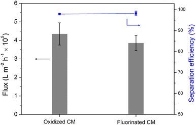 | ||
| Fig. 5 The separation performances of the dual-membrane integrated system towards vegetable oil/water mixture. | ||
3.4 Separation mechanism of the modified meshes
The underlying mechanism behind the separation of oil–water mixtures using both the fluorinated copper mesh and oxidized copper mesh was investigated. The wetting behavior of a droplet on a solid surface depends on the surface tension of the liquid and the surface energy of the solid. In Fig. S6,† a simplified schematic illustrating droplet transport through an individual pore on the copper mesh was presented. By utilizing the Laplace equation, the motion of the droplet within the pore was analyzed. The parameter R represents the radius of a single copper wire, r represents the curvature radius of the liquid–gas interface, O1O2 denotes the distance between the centers of two adjacent copper wires, and 2D represents the shortest distance between the surfaces of two adjacent copper wires. The additional pressure exerted on the liquid–gas interface is directed towards the center of the arc-shaped circle and can be mathematically expressed as:The superhydrophobic/superoleophilic mesh exhibits different behavior towards oil and water droplets due to variations in their surface tensions. Oil droplets, having lower surface tension, create a contact angle θ < 90° on the copper mesh surface, resulting in a downward Laplace pressure that enables spontaneous passage through the mesh. Conversely, water droplets, with higher surface tension, form a contact angle θ > 90° on the copper mesh surface, leading to an upward Laplace pressure that prevents them from passing through the mesh. The opposite Laplace pressures acting on these droplets serve as the primary mechanism for achieving efficient oil–water separation.
4 Conclusions
In this study, superhydrophilic/underwater superoleophobic and superoleophilic/superhydrophobic porous separation membranes based on metal copper meshes were prepared by in situ solution oxidation and gas-phase deposition methods, respectively. Continuous and efficient oil–water separation can be achieved by integrating two meshes with reverse wettability into a T-shaped device. Both the oil and water removal meshes exhibited high flux. The oxidized copper mesh achieved a flux of 7–8 × 10⁵ L m−2 h−1, while the fluorinated copper mesh achieved a flux of 6–7 × 10⁵ L m−2 h−1. The efficiency of both oil and water removal remained above 97.0% after 15 days of continuous separation, demonstrating the excellent oil–water separation performance of the integrated T-shaped device. The opposite Laplace pressures acting on oil and water droplets on the copper mesh surface are the fundamental reasons for oil–water separation. The designed dual-membrane integrated system achieves continuous and sustainable separation while maintaining high separation efficiency, offering a new low-cost and scalable approach for treating oily wastewater compared to traditional single-membrane systems.In real-world applications like industrial effluent treatments from the textile and metal refining industries, achieving efficient oil–water separation is significantly challenging due to the presence of heavy metal contaminants. These contaminants can adversely react with copper mesh, forming toxic compounds because of redox potential differences, which compromises separation efficiency. To address this, our future focus will be on developing and optimizing pre-treatment processes that can effectively remove or neutralize these contaminants before separation, ensuring the robustness and efficacy of the copper-based separation technology in various industrial scenarios.
Author contributions
Zhaohe Huang performed the experiments, analyzed the data, wrote the original manuscript and revised manuscript. Zhenzhong Wang and Shiqiang Wang helped in manuscript writing and revising. XiaoWen Shan and Shumeng Yin helped in analyzing the experimental data. Bin Tao was the supervisor for this research project.Conflicts of interest
The authors declare no conflict of interest.Acknowledgements
We are grateful for the financial support from the Ministry of Science and Technology of China Petroleum and Chemical Corporation (319006-5).Notes and references
- X. Yue, Z. Li, T. Zhang, D. Yang and F. Qiu, Chem. Eng. J., 2019, 364, 292–309 CrossRef CAS.
- B. Li, B. Qi, Z. Guo, D. Wang and T. Jiao, Chemosphere, 2023, 138528 CrossRef CAS.
- Y. Zhang, X. Wang, C. Wang, J. Liu, H. Zhai, B. Liu, X. Zhao and D. Fang, RSC Adv., 2018, 8, 35150–35156 RSC.
- J. Li, L. Yan, H. Li, J. Li, F. Zha and Z. Lei, RSC Adv., 2015, 5, 53802–53808 RSC.
- Z. Chu, Y. Feng and S. Seeger, Angew. Chem., Int. Ed., 2015, 54, 2328–2338 CrossRef CAS.
- J. Yong, F. Chen, Q. Yang, J. Huo and X. Hou, Chem. Soc. Rev., 2017, 46, 4168–4217 RSC.
- P. Calcagnile, D. Fragouli, I. S. Bayer, G. C. Anyfantis, L. Martiradonna, P. D. Cozzoli, R. Cingolani and A. Athanassiou, ACS Nano, 2012, 6, 5413–5419 CrossRef CAS.
- L. Zhang, Y. Zhong, D. Cha and P. Wang, Sci. Rep., 2013, 3, 2326 CrossRef PubMed.
- J. Abraham, K. S. Vasu, C. D. Williams, K. Gopinadhan, Y. Su, C. T. Cherian, J. Dix, E. Prestat, S. J. Haigh and I. V. Grigorieva, Nat. Nanotechnol., 2017, 12, 546–550 CrossRef CAS.
- M. M. Pendergast and E. M. Hoek, Energy Environ. Sci., 2011, 4, 1946–1971 RSC.
- Y. Liu, P. Xu, W. Ge, C. Lu, Y. Li, S. Niu, J. Zhang and S. Feng, RSC Adv., 2021, 11, 17740–17745 RSC.
- C. Yang, F. Topuz, S.-H. Park and G. Szekely, Green Chem., 2022, 24, 5291–5303 RSC.
- A. Alammar, R. Hardian and G. Szekely, Green Chem., 2022, 24, 365–374 RSC.
- K. Liu and L. Jiang, Nano Today, 2011, 6, 155–175 CrossRef CAS.
- F. Xia and L. Jiang, Adv. Mater., 2008, 20, 2842–2858 CrossRef CAS.
- Z. Liu, J. Yang, J. Jing, X. Zhang, Y. Fu, M. Li, R. Yuan and H. Wang, J. Mater. Chem. A, 2023, 11, 18081–18088 RSC.
- B. Xiang, Q. Liu, Q. Sun, J. Gong, P. Mu and J. Li, Chem. Commun., 2022, 58, 13413–13438 RSC.
- J. Li, R. Kang, Y. Zhang, M. Li, H. She, F. Zha and Z. Lei, RSC Adv., 2016, 6, 90824–90830 RSC.
- C. Hou and C. Cao, RSC Adv., 2021, 11, 31675–31687 RSC.
- J. Cavalcante and G. Szekely, J. Mater. Chem. A, 2023, 11, 24598–24607 RSC.
- B. Li, C. Qu, S. Wang, J. C. C. Yeo, N. E. B. Surat’man, X. J. Loh, Z. Li and T.-S. Chung, J. Membr. Sci., 2024, 693, 122378 CrossRef CAS.
- L. Feng, Z. Zhang, Z. Mai, Y. Ma, B. Liu, L. Jiang and D. Zhu, Angew. Chem., 2004, 116, 2046–2048 CrossRef.
- Z. Huang, S. Yin, J. Zhang and N. Zhang, J. Appl. Polym. Sci., 2021, 138, 50587 CrossRef CAS.
- Z. Xue, S. Wang, L. Lin, L. Chen, M. Liu, L. Feng and L. Jiang, Adv. Mater., 2011, 23, 4270–4273 CrossRef CAS.
- S. Gao, J. Sun, P. Liu, F. Zhang, W. Zhang, S. Yuan, J. Li and J. Jin, Adv. Mater., 2016, 28, 5307–5314 CrossRef CAS PubMed.
- G. J. Dunderdale, C. Urata, T. Sato, M. W. England and A. Hozumi, ACS Appl. Mater. Interfaces, 2015, 7, 18915–18919 CrossRef CAS.
- W. Wu, H. Zhang, Z. Qiao, X. Cai, G. Liao and T. Lei, Water Sci. Technol., 2023, 88, 2264–2270 CrossRef CAS.
- H. Hou, Y. Xie and Q. Li, Cryst. Growth Des., 2005, 5, 201–205 CrossRef CAS.
- X. Wen, W. Zhang, S. Yang, Z. R. Dai and Z. L. Wang, Nano Lett., 2002, 2, 1397–1401 CrossRef CAS.
- E. Said-Galiev, L. Nikitin, A. Y. Nikolaev, Y. E. Vopilov, I. Garbuzova, A. Khokhlov and V. Buznik, Polym. Sci., Ser. A, 2015, 57, 271–278 CrossRef CAS.
- G. Nansé, E. Papirer, P. Fioux, F. Moguet and A. Tressaud, Carbon, 1997, 35, 175–194 CrossRef.
- T. Okpalugo, P. Papakonstantinou, H. Murphy, J. McLaughlin and N. Brown, Carbon, 2005, 43, 153–161 CrossRef CAS.
- J. Liu, W. Li, L. Duan, X. Li, L. Ji, Z. Geng, K. Huang, L. Lu, L. Zhou and Z. Liu, Nano Lett., 2015, 15, 5137–5142 CrossRef CAS PubMed.
- N. Gauthier, C. Courrèges, J. Demeaux, C. Tessier and H. Martinez, Appl. Surf. Sci., 2020, 501, 144266 CrossRef CAS.
- N. Zhang, N. Yang, L. Zhang, B. Jiang, Y. Sun, J. Ma, K. Cheng and F. Peng, Chem. Eng. J., 2020, 402, 126200 CrossRef CAS.
Footnote |
| † Electronic supplementary information (ESI) available. See DOI: https://doi.org/10.1039/d3ra08909f |
| This journal is © The Royal Society of Chemistry 2024 |


