 Open Access Article
Radiation polymerization for the preparation of universal coatings: remarkable anti-fogging and frost-resisting performance†
Wenrui Wangab,
Qi Liuab,
Ying Sunab,
Danyi Liab,
Siyi Xuab,
Lin Linab,
Fangzheng Wangab,
Linfan Li *abc and
Jihao Li
 *abc
*abc
aShanghai Institute of Applied Physics, Chinese Academy of Sciences, Shanghai 201800, China. E-mail: lilinfan@sinap.ac.cn; lijihao@sinap.ac.cn
bUniversity of Chinese Academy of Sciences, Beijing 100049, China
cWuwei Institute of New Energy, Gansu 733000, China
First published on 26th March 2024
Abstract
Hydrophilic anti-fogging coatings have attracted considerable attention due to their ease of preparation and excellent fog resistance. In this study, a hydrophilic anti-fogging coating based on the random copolymer p(AA-co-SAS) was prepared using acrylic acid (AA) and sodium allylsulfonate (SAS) as monomers through radiation polymerization. The introduction of SAS successfully transformed the random copolymer from a gel state into a film-forming polymer solution. The presence of AA structural units in p(AA-co-SAS) improved the film-forming properties of the polymer solution. Additionally, there was a positive correlation between the proportion of SAS structural units in the random copolymer and the scratch hardness and wetting properties of the coating. After coating polycarbonate (PC) sheets, the surface hydrophilicity was significantly enhanced, with the contact angle of PC-AA10/SAS5 decreasing from 100.1° to 18.8° within 50 seconds. The outstanding wetting properties endowed the coating with exceptional anti-fogging and frost-resisting performance. It exhibited optimal transparency under both testing conditions and demonstrated good stability during cyclic testing. Tape adhesion tests indicated that the adhesion between the coating and PC reached a 5B level. When AA10/SAS5 was applied to PET film, glass, and PMMA goggles, all samples showed excellent anti-fog performance. Even after being naturally placed for one year under ambient conditions, the PMMA goggles still maintained good performance in the anti-fog and frost resistance tests. The remarkable comprehensive properties of the polymer coating based on p(AA-co-SAS) suggest enormous potential applications in industries such as packaging, healthcare, and optical equipment.
1 Introduction
Fogging is a common phenomenon in daily life. Water vapor condenses on surfaces to form droplets when the temperature (T) of the solid surface is lower than the dew point (Td) of the surrounding air steam mixture.1,2 Due to the small radius of curvature of the interface between the droplet and the air, the scattering effect on the incident light is strong, which leads to a reduction in the transmittance.3 Fogging is universally known to have a negative impact on the efficiency and clarity of many devices, such as lenses, goggles, greenhouse films and windshields.4–12The current anti-fogging strategies are mainly divided into physical and chemical methods: (1) by adjusting temperature, humidity, and increasing air flow at the interface, thus preventing water vapor from condensing on the surface; (2) superhydrophobic surfaces that repel droplets from the surface;13,14 (3) superhydrophilic surfaces that spread droplets into a water film.15,16 The formation of superhydrophobic surfaces requires specially hierarchical surface topography; these designs usually need a complex operation process limiting their practical application.17 The superhydrophilic surfaces can be made of either polymers and inorganic materials or a mixture of the two (composite materials). Inorganic materials are mainly deposited on the surface of the substrate, such as La(OH)3, SiO2, TiO2 (ref. 18–20) etc. Although the superhydrophilicity endowed by inorganic materials makes them have good antifogging performance under high temperature and high humidity conditions, when it comes to low temperature, the surface is still prone to fogging or even frosting.
Given the disadvantages of inorganic materials for use in a low-temperature environment, polymer coatings have gained increasing attention in recent years due to the distinctive properties they offer, including the ability to coat thermally sensitive materials, as well as being non-toxic and environmentally friendly. These polymer coatings contain hydrophilic functional groups such as hydroxyl(OH), carboxyl(COOH), amide(NHCOR), amine(NH2) and sulhonic(SO3H). Lee prepared coatings with anti-fogging and anti-frosting properties by introducing oligoethylene glycol (OEG) groups. They used a polysaccharide-based film composed of chitosan (CHI) and carboxymethyl cellulose (CMC) as the model system.21 Cai reported on the use of (Methacryloyloxy)ethyldimethyl-(3-sulfopropyl) (SBMA) and Itaconic acid (IA) as functional ingredients in amphoteric coatings with anti-fouling and self-healing properties.22
The study of traditional free radical polymerization has a long and well-established history, with extensive research and understanding of its reaction mechanism.23–26 Currently, this method is primarily used for synthesizing anti-fog polymer coatings.22,27–32 Radiation polymerization is a novel technique rooted in the theory of free radical polymerization. It employs radiation sources such as electron beams, gamma rays, and ultraviolet light to break carbon–carbon double bonds in monomer molecules, resulting in free radicals that trigger chain reactions, leading to the formation of large polymer molecules.33–35 Compared to traditional free radical polymerization, radiation polymerization offers several advantages: (1) it is a straightforward process involving the preparation of a reaction solution and exposure to high-energy radiation under a nitrogen atmosphere.36 (2) Unlike chemical initiators, radiation polymerization does not require additional initiators, ensuring pure polymer products. (3) Radiation polymerization provides a consistent source of free radicals unaffected by temperature and time, facilitating the production of high molecular weight products and achieving high conversion rates. (4) The reaction rate constant (Rp) in radiation polymerization is minimally influenced by temperature, allowing it to be carried out at low or room temperature.37 This reduces the occurrence of side reactions common in traditional free radical polymerization under high temperatures and improves the regularity of polymer structure.
Considering the significant potential of polymer coatings in anti-fogging applications and the benefits of radiation polymerization, this research work combines the two innovatively. Co60 is utilized as the radiation source, while AA and SAS are employed as functional components. Gamma rays are used to create anti-fogging and frost-resisting coatings based on the random copolymer p(AA-co-SAS) under room temperature conditions. The absence of initiators ensures high product purity during the reaction process. By introducing SAS, the random copolymer transitions from a gel to a film-forming polymer solution. The presence of AA structural units enhances the coating's film-forming performance. The study's findings demonstrate that higher proportions of SAS structural units in p(AA-co-SAS) result in better scratch hardness and wetting properties of the coatings. Among the tested compositions, AA10/SAS5 exhibits superior light transmittance after anti-fogging and frost-resisting tests. It also demonstrates good stability during cyclic testing and achieves a 5B tape adhesion level, indicating excellent adherence to PC substrates. Additionally, the coatings show some degree of abrasion resistance. When applied to PET films, PMMA goggles, and glass surfaces, the coated samples display outstanding anti-fogging and frost-resisting performance. Even after one year indoors, the PMMA goggles maintain their excellent performance, highlighting the coatings' long-term durability and environmental stability. In conclusion, coatings based on the random copolymer p(AA-co-SAS), prepared through radiation polymerization, exhibit exceptional comprehensive properties.
2. Experimental sections
2.1 Materials
Acrylic acid (AA, AR) and sodium allylsulfonate (SAS, 94%) were purchased from Sinopharm Chemical Reagent Co., Ltd. Deionized water is home-made in the lab. PC, PET, glass slides and goggles are commercially available. Gamma ray sources (Co60, 1.5 × 10⁵Ci) is attributed to the Shanghai Shilong Technology Co. All reagents were not further purified before use.2.2 Synthesis of hydrophilic coating solution
A schematic diagram illustrating the synthesis of the hydrophilic coating is presented in Fig. 1(a). AA and SAS were accurately weighed and added to glass reagent bottles containing deionized water. The mixture was then sonicated for 10 minutes to ensure proper dispersion. The total mass of the solution was 100 g, with AA having a mass fraction of 10% and SAS having mass fractions of 0%, 1%, 3%, 5%, 7%, and 10% in solutions numbered 1, 2, 3, 4, 5, and 6 respectively. The solutions were labeled in descending order based on the mass fraction of SAS.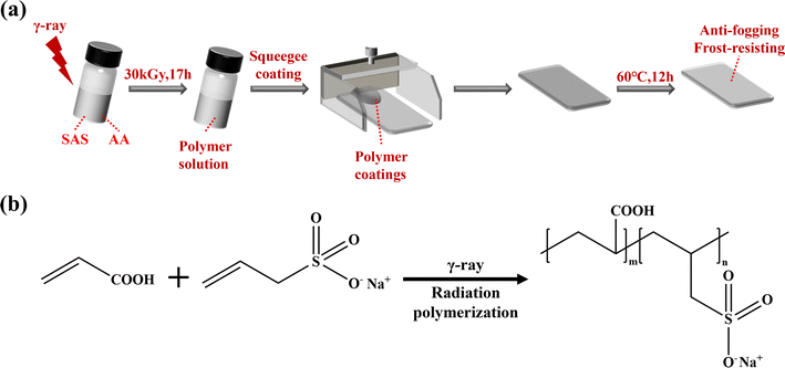 | ||
| Fig. 1 (a) Flow chart for the preparation of anti-fogging coatings; (b) schematic illustration of the synthesis of p(AA-co-SAS). | ||
The sample vials containing the aforementioned solution were purged with nitrogen for 10 minutes and sealed. They were then placed in the gamma ray source and subjected to irradiation with gamma rays for a radiation polymerization reaction at an absorbed dose of 30 kGy for 17 hours. The hydrophilic coating solution was obtained after irradiation.
2.3 Preparation of anti-fogging coatings
The PC, PET, glass slides and goggles were ultrasonic cleaned with deionized water, ethanol, and deionized water, respectively. They were then dried in a blast oven at 60 °C for 12 h and kept as a reserve.The PC surface was coated using the scraping method, whereby the squeegee was adjusted to be 2 mm away from the lower substrate. The coating was applied to the front of the squeegee and pulled at a constant speed of 1 cm s−1 to ensure an even distribution across the substrate's surface. The coated substrate was subsequently dried in a blast oven at 60 °C for 12 hours. the other side of the substrate was treated in the same way. The coatings were designated as AAm/SASn, where m and n denote the mass fraction of AA and SAS in the unirradiated solution respectively.
2.4 Characterization
Final characterization of functional groups related to the random copolymer was determined using a Fourier-transform infrared spectrometer (Bruker VERTEX 70 V). The attenuated total reflection mode (ATR) was employed for the measurements with a range of 4000 to 600 cm−1, resolution of 4 cm−1, and 32 scans.
The surface morphology of the coatings was examined with a scanning electron microscope (JSM-6700F JEOL). Before testing, the samples underwent a gold sputter coating for 120 seconds. The observations were conducted using an acceleration voltage of 5 kV, while the energy-dispersive spectroscopy (EDS) analysis was carried out at a voltage of 15 kV.
3 Results and discussion
Table 1 reflects the composition, reaction conditions, and post-reaction state of the precursor solution. Acrylic acid (AA), as a monomer, is commonly used as a functional component in radiation chemistry due to its high free radical yield and reactivity. In this experiment, the AA mass fraction was 10% for all groups. As shown in Fig. 2, when the current carrier solution contained only AA, it directly formed a hydrogel upon irradiation at the current absorbed dose. When the mass fraction of SAS was 1%, the precursor solution maintained its gel state after irradiation. Increasing the SAS mass fraction to 3% resulted in the precursor solution no longer forming a hydrogel, but instead forming a polymer solution after irradiation. Further increasing the SAS mass fraction to 10% resulted in the formation of a polymer solution in the precursor solution after irradiation for all groups. Video 1 in the ESI† provides a visual representation of this transformation process. Therefore, the addition of SAS can be observed to decrease the degree of gelation of AA during irradiation, transforming the precursor solution from a hydrogel into a viscous fluid suitable for squeegee coating.| Solution | AA/g | SAS/g | H2O/g | Absorbed dose/kGy | Radiation time/h | Post-radiation state |
|---|---|---|---|---|---|---|
| 1 | 10 | 0 | 90 | 30 | 17 | Gel |
| 2 | 10 | 1 | 89 | 30 | 17 | Gel |
| 3 | 10 | 3 | 87 | 30 | 17 | Viscous fluid |
| 4 | 10 | 5 | 85 | 30 | 17 | Viscous fluid |
| 5 | 10 | 7 | 83 | 30 | 17 | Viscous fluid |
| 6 | 10 | 10 | 80 | 30 | 17 | Viscous fluid |
GPC analysis using H2O as the solvent characterized the molecular weight and polydispersity of the coatings, results are presented in Table 2. The relative molecular weights for AA10/SAS0 and AA10/SAS1 unable to be determined due to their hydrogel nature. All coatings consisted of four components as shown by GPC curves in Fig. S4.† The first component was a high molecular weight polymer. With increasing SAS content, its number average molecular weight decreased gradually, while the weight average initially increased and then decreased. The molecular weight distribution (PDI) displayed an increasing–decreasing trend, indicating narrow distributions and contributing to excellent performance. The remaining three components were low molecular weight oligomers with no significant changes in Mn, Mw, and PDI even with varying SAS content. In comparison to conventional free radical polymerization methods, γ-rays offer excellent penetration capability and uniformly irradiate each monomer molecule, efficiently initiating free radical polymerization by breaking the carbon–carbon double bonds within the monomer molecules. This process results in the production of higher molecular weight polymer products. In this experiment, water was employed as the solvent, serving as an effective solvent for the polymerization products. It effectively delayed the gelation effect while promoting a higher molecular weight of the polymer.
| Coatinga | Mnb | Mwb | Mzb | Mvb | PDIc |
|---|---|---|---|---|---|
| a Coating were prepared at room temperature, see Experimental sections.b Molecular weights were measured by GPC.c PDI, Mw/Mn. | |||||
| AA10/SAS3 | 221![[thin space (1/6-em)]](https://www.rsc.org/images/entities/char_2009.gif) 182 182 |
457![[thin space (1/6-em)]](https://www.rsc.org/images/entities/char_2009.gif) 674 674 |
782![[thin space (1/6-em)]](https://www.rsc.org/images/entities/char_2009.gif) 545 545 |
415![[thin space (1/6-em)]](https://www.rsc.org/images/entities/char_2009.gif) 074 074 |
2.07 |
| 2494 | 2505 | 2516 | 2504 | 1.00 | |
| 1404 | 1430 | 1457 | 1426 | 1.02 | |
| 658 | 662 | 665 | 661 | 1.01 | |
| AA10/SAS5 | 219![[thin space (1/6-em)]](https://www.rsc.org/images/entities/char_2009.gif) 228 228 |
538![[thin space (1/6-em)]](https://www.rsc.org/images/entities/char_2009.gif) 770 770 |
903![[thin space (1/6-em)]](https://www.rsc.org/images/entities/char_2009.gif) 772 772 |
487![[thin space (1/6-em)]](https://www.rsc.org/images/entities/char_2009.gif) 338 338 |
2.46 |
| 2494 | 2547 | 2604 | 2539 | 1.02 | |
| 1466 | 1493 | 1519 | 1489 | 1.02 | |
| 670 | 675 | 680 | 675 | 1.01 | |
| AA10/SAS7 | 129![[thin space (1/6-em)]](https://www.rsc.org/images/entities/char_2009.gif) 622 622 |
371![[thin space (1/6-em)]](https://www.rsc.org/images/entities/char_2009.gif) 085 085 |
685![[thin space (1/6-em)]](https://www.rsc.org/images/entities/char_2009.gif) 779 779 |
328![[thin space (1/6-em)]](https://www.rsc.org/images/entities/char_2009.gif) 671 671 |
2.86 |
| 2580 | 2641 | 2707 | 2631 | 1.02 | |
| 1475 | 1500 | 1524 | 1496 | 1.02 | |
| 675 | 682 | 690 | 681 | 1.01 | |
| AA10/SAS10 | 131![[thin space (1/6-em)]](https://www.rsc.org/images/entities/char_2009.gif) 128 128 |
329![[thin space (1/6-em)]](https://www.rsc.org/images/entities/char_2009.gif) 223 223 |
595![[thin space (1/6-em)]](https://www.rsc.org/images/entities/char_2009.gif) 609 609 |
294![[thin space (1/6-em)]](https://www.rsc.org/images/entities/char_2009.gif) 012 012 |
2.51 |
| 2552 | 2634 | 2727 | 2621 | 1.03 | |
| 1486 | 1505 | 1524 | 1502 | 1.01 | |
| 645 | 651 | 656 | 650 | 1.01 | |
The NMR hydrogen spectra of all coatings were tested using D2O as a solvent, and the results are presented in Fig. 3. In Fig. 3(a), the 1H NMR spectrum of PAA displayed absorption peaks at δ = 1.63, 1.77, and 1.94 ppm from the –CH2 group, δ = 2.41 ppm from the –CH group, and possibly an impurity peak at δ = 2.75 ppm. The synthesized random copolymer was named n-p(AA-co-SAS), where “n” represents the corresponding reaction solution number from Table 1. The longitudinal comparison between the spectra of PAA and n-p(AA-co-SAS) is shown in Fig. 3(b). n-p(AA-co-SAS) exhibited proton absorption peaks from both –CH2–(a) and –CH–(b) groups, which had similar chemical shifts to those observed in PAA. The impurity peak at 2.75 ppm was still present. Additionally, the characteristic proton absorption peaks within the range of δ = 2.89–3.15 ppm, attributed to the –CH2SO3− group of SAS, were observed in the H1NMR spectra (Fig. 3(c) and (d)) of n-p(AA-co-SAS).38–40 These observations indicated the successful copolymerization of AA with SAS. Proton absorption peaks on the carbon–carbon double bonds were detected between 4.5 and 6.5 ppm, indicating the presence of unreacted AA and SAS in the polymer solution. Furthermore, the absorption peak at δ = 3.63 ppm corresponded to –CH2SO3− in unreacted SAS. Assuming the integral areas in the ranges of 4.5–6.5 ppm, 3.63 ppm, c, and b are represented by A, B, C, and D respectively, the composition ratio of AA structural units to SAS structural units, the conversion ratio of the two monomers in the radiation polymerization of poly(AA-co-SAS) can be calculated using the provided formula:
 | (1) |
 | (2) |
 | (3) |
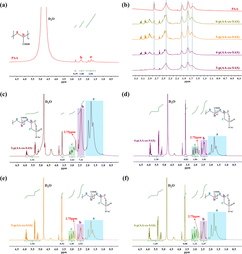 | ||
| Fig. 3 1H NMR spectrum of samples: (a) PAA; (b) PAA and n-p(AA-co-SAS); (c) 3- p(AA-co-SAS); (d) 4-p(AA-co-SAS); (e) 5-p(AA-co-SAS); (f) 6-p(AA-co-SAS). | ||
Table 3 showcases the calculations for X(SAS)/X(AA), representing the molar ratio of SAS to AA structural units in p(AA-co-SAS), as well as θ(SAS) and θ(AA), indicating the conversion rates of the monomers.
M(SAS)![[thin space (1/6-em)]](https://www.rsc.org/images/entities/char_2009.gif) : :![[thin space (1/6-em)]](https://www.rsc.org/images/entities/char_2009.gif) N(AA) N(AA) |
m(SAS)![[thin space (1/6-em)]](https://www.rsc.org/images/entities/char_2009.gif) : :![[thin space (1/6-em)]](https://www.rsc.org/images/entities/char_2009.gif) n(AA) n(AA) |
X(SAS)![[thin space (1/6-em)]](https://www.rsc.org/images/entities/char_2009.gif) : :![[thin space (1/6-em)]](https://www.rsc.org/images/entities/char_2009.gif) X(AA) X(AA) |
θ(SAS) | θ(AA) |
|---|---|---|---|---|
a M![[thin space (1/6-em)]](https://www.rsc.org/images/entities/char_2009.gif) : :![[thin space (1/6-em)]](https://www.rsc.org/images/entities/char_2009.gif) N represents the mass ratio of monomers before reaction (SAS N represents the mass ratio of monomers before reaction (SAS![[thin space (1/6-em)]](https://www.rsc.org/images/entities/char_2009.gif) : :![[thin space (1/6-em)]](https://www.rsc.org/images/entities/char_2009.gif) AA). m AA). m![[thin space (1/6-em)]](https://www.rsc.org/images/entities/char_2009.gif) : :![[thin space (1/6-em)]](https://www.rsc.org/images/entities/char_2009.gif) n represents the molar ratio of monomers before reaction (SAS n represents the molar ratio of monomers before reaction (SAS![[thin space (1/6-em)]](https://www.rsc.org/images/entities/char_2009.gif) : :![[thin space (1/6-em)]](https://www.rsc.org/images/entities/char_2009.gif) AA). AA). |
||||
3![[thin space (1/6-em)]](https://www.rsc.org/images/entities/char_2009.gif) : :![[thin space (1/6-em)]](https://www.rsc.org/images/entities/char_2009.gif) 10 10 |
1![[thin space (1/6-em)]](https://www.rsc.org/images/entities/char_2009.gif) : :![[thin space (1/6-em)]](https://www.rsc.org/images/entities/char_2009.gif) 6.67 6.67 |
1![[thin space (1/6-em)]](https://www.rsc.org/images/entities/char_2009.gif) : :![[thin space (1/6-em)]](https://www.rsc.org/images/entities/char_2009.gif) 8.06 8.06 |
88.33% | 98.19% |
5![[thin space (1/6-em)]](https://www.rsc.org/images/entities/char_2009.gif) : :![[thin space (1/6-em)]](https://www.rsc.org/images/entities/char_2009.gif) 10 10 |
1![[thin space (1/6-em)]](https://www.rsc.org/images/entities/char_2009.gif) : :![[thin space (1/6-em)]](https://www.rsc.org/images/entities/char_2009.gif) 4.00 4.00 |
1![[thin space (1/6-em)]](https://www.rsc.org/images/entities/char_2009.gif) : :![[thin space (1/6-em)]](https://www.rsc.org/images/entities/char_2009.gif) 2.46 2.46 |
78.99% | 98.59% |
7![[thin space (1/6-em)]](https://www.rsc.org/images/entities/char_2009.gif) : :![[thin space (1/6-em)]](https://www.rsc.org/images/entities/char_2009.gif) 10 10 |
1![[thin space (1/6-em)]](https://www.rsc.org/images/entities/char_2009.gif) : :![[thin space (1/6-em)]](https://www.rsc.org/images/entities/char_2009.gif) 2.86 2.86 |
1![[thin space (1/6-em)]](https://www.rsc.org/images/entities/char_2009.gif) : :![[thin space (1/6-em)]](https://www.rsc.org/images/entities/char_2009.gif) 2.40 2.40 |
82.93% | 97.10% |
10![[thin space (1/6-em)]](https://www.rsc.org/images/entities/char_2009.gif) : :![[thin space (1/6-em)]](https://www.rsc.org/images/entities/char_2009.gif) 10 10 |
1![[thin space (1/6-em)]](https://www.rsc.org/images/entities/char_2009.gif) : :![[thin space (1/6-em)]](https://www.rsc.org/images/entities/char_2009.gif) 2.00 2.00 |
1![[thin space (1/6-em)]](https://www.rsc.org/images/entities/char_2009.gif) : :![[thin space (1/6-em)]](https://www.rsc.org/images/entities/char_2009.gif) 2.77 2.77 |
81.70% | 96.97% |
Based on the findings in Fig. 4, it is evident that the proportion of SAS structural units in p(AA-co-SAS) initially increases and then decreases as the SAS content increases. Similarly, the conversion rate of SAS exhibits a decrease followed by an increase, while the conversion rate of AA shows a slight decrease.
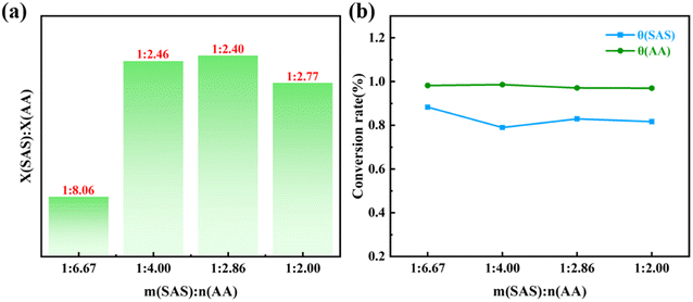 | ||
| Fig. 4 (a) Histogram of feeding ratio versus structural unit composition ratio in p(AA-co-SAS); (b) relationship between feed ratio and monomer conversion. | ||
The formation of hydrogel under the action of γ-ray generally undergoes the following process: (1) the carbon–carbon double bond in the monomer breaks under the action of radiation, generating reactive free radicals that trigger the polymerization reaction to form polymers. (2) As the polymer chains grow, the molecular weight of the polymer gradually increases, and its solubility in solvents decreases, resulting in stronger entanglement between the chains. (3) When these molecular chains are irradiated with γ-rays, free radicals are generated on the chains. In cases where the degree of entanglement is too high, the free radicals between the chains combine with each other to form chemical bonds. When a sufficient number of bonds are formed, the polymer forms a three-dimensional network structure called a hydrogel.
Based on the results of GPC and 1H NMR analysis, it is suggested that SAS plays the following two roles in the polymerization process, leading to the gradual conversion of the AA and SAS copolymer from a hydrogel into a viscous polymer solution: (a) the introduction of SAS reduces the number-average molecular weight of ploy(AA-co-SAS), improving the polymer's solubility in water and weakening the intertwining effect between the molecular chains. (b) The presence of SAS structural units in poly(AA-co-SAS) imparts amphoteric polymer properties to the polymer, giving it excellent hydration ability and significantly enhancing its solubility in water.
In order to assess the film-forming properties of the coatings, various coating systems were applied to glass surfaces using a scraping technique. After drying, the coated samples were visually examined to evaluate their initial film-forming performance, as depicted in Fig. 5. When the coating consisted solely of PSAS, its film-forming performance was inadequate. The surface of the coating exhibited irregularities along with numerous cracks and wrinkles. Moreover, the transparency of the coated glass was substantially reduced, resulting in a blurred logo visibility. However, with the introduction of AA and subsequent synthesis of p(AA-co-SAS) through radiation polymerization, the film-forming properties of the coating improved significantly.41,42 The polymer coating displayed a smooth and uniform surface while maintaining satisfactory light transmission after application to the substrate.
To summarize, under the given absorbed dose, the incorporation of SAS effectively transformed the precursor solution from a hydrogel into a viscous fluid capable of forming films. The addition of AA had a notable impact on enhancing the film-forming behavior of the polymer solution. The synergy between AA and SAS was vital for achieving optimal results.
In the ATR spectra (Fig. 6(a)), the coated PC exhibited a broad absorption peak around 3400 cm−1, which was attributed to the vibrational absorption of –COOH in comparison to the bare PC. The peak at 1715 cm−1 was identified as the stretching vibration of C![[double bond, length as m-dash]](https://www.rsc.org/images/entities/char_e001.gif) O in –COOH. Furthermore, the peaks at 1040 cm−1 and 660 cm−1 corresponded to the stretching vibration of S
O in –COOH. Furthermore, the peaks at 1040 cm−1 and 660 cm−1 corresponded to the stretching vibration of S![[double bond, length as m-dash]](https://www.rsc.org/images/entities/char_e001.gif) O in –SO3−.22,40 Additionally, the peak at 1650 cm−1 indicated the bending vibration of C
O in –SO3−.22,40 Additionally, the peak at 1650 cm−1 indicated the bending vibration of C![[double bond, length as m-dash]](https://www.rsc.org/images/entities/char_e001.gif) C, suggesting the presence of unreacted monomers in the coating. These observations align with the findings from the H1NMR studies, where non-polymerized AA and SAS were detected as peaks between 6.5 and 4.5 ppm in the 1H NMR spectrum (Fig. 3(e) and (f)).
C, suggesting the presence of unreacted monomers in the coating. These observations align with the findings from the H1NMR studies, where non-polymerized AA and SAS were detected as peaks between 6.5 and 4.5 ppm in the 1H NMR spectrum (Fig. 3(e) and (f)).
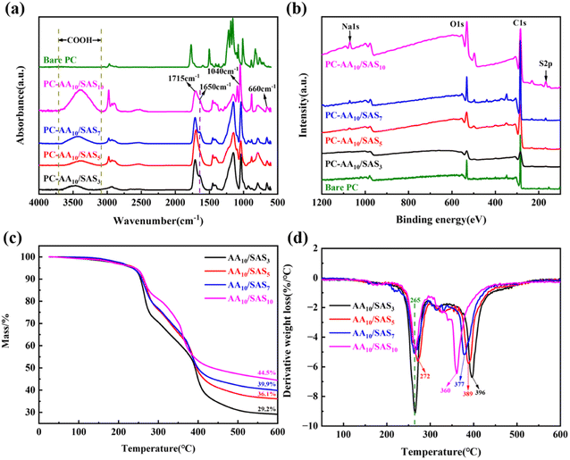 | ||
| Fig. 6 (a) ATR spectra of bare and coated PC; (b) XPS survey spectra; (b) TG curve for coatings; (d) DTG curve for coatings. | ||
XPS analysis was performed to analyze the elements on the surface of the coated PC, as shown in Fig. 6(b). For the bare PC, distinct peaks were observed at 285 eV for C 1s and 532 eV for O 1s. After coating the PC surface with the material, peaks at 168 eV for S 2p and 1072 eV for Na 1s were observed, with the intensities increasing as the SAS content in the coating system increased. The high-resolution XPS spectrum of PC-AAm/SASn is shown in Fig. S5,† revealing the presence of three types of sulfur bonding in this coating: S![[double bond, length as m-dash]](https://www.rsc.org/images/entities/char_e001.gif) O near 169.5 eV, S–O near 168 eV, and C–S near 164 eV.43 Combining the XPS and ATR analyses, it can be concluded that the irradiation-induced coating was successfully deposited on the PC surface. The surface coatings contain both –COOH and –SO3− functional groups, which are expected to enhance the surface wettability.
O near 169.5 eV, S–O near 168 eV, and C–S near 164 eV.43 Combining the XPS and ATR analyses, it can be concluded that the irradiation-induced coating was successfully deposited on the PC surface. The surface coatings contain both –COOH and –SO3− functional groups, which are expected to enhance the surface wettability.
The investigation into the weight loss rate of AAm/SASn coatings at different decomposition temperatures was conducted using TG to compare the thermal stability of the coatings. As depicted in Fig. 6(c), the weight loss of the polymer can be categorized into 4 stages. In the first stage, 30 °C to 100 °C, the primary loss is the free water absorbed by the polymer coating. The second stage, 100–300 °C, is characterized by the loss of bound water in the coating and the decomposition of the –COO− groups.44 At 300 °C, the residual mass of the coating is 71% with a SAS mass fraction of 3%, and as the SAS content increases, the residual mass at 300 °C progressively rises, reaching 81% at a SAS mass fraction of 10%. The DTG curve in Fig. 6(d) illustrates that the addition of SAS can decrease the maximum thermal decomposition rate of the –COO− groups. The maximum thermal decomposition rate of AA10/SAS10 is approximately half that of AA10/SAS3, demonstrating that the inclusion of SAS diminishes the thermal decomposition of the –COO− groups in the second stage and enhances the thermal stability of the coating at 300 °C. It is noteworthy that the temperature corresponding to the maximum thermal decomposition rate of AA10/SAS5 is slightly increased to 272 °C, in contrast to the 265 °C observed for the remaining coatings. The third stage, 300 °C to 400 °C, mainly involves the decomposition of SO3− in the polymer structure.45 While the fourth stage, 400 °C to 600 °C, primarily entails the thermal decomposition of the polymer chain.22 From 400 °C to 600 °C, the TG curves of the coatings with high SAS content consistently exceed those of the coatings with low SAS content, indicating that the addition of SAS moderately enhances the thermal stability of the polymer backbone.
The surface morphology of the coatings was observed directly through SEM photographs. The SEM images in Fig. 7(a)–(d) demonstrate that all the current coatings exhibit smooth, flat, and dense surfaces without any holes or cracks. This indicates the excellent performance of the polymer coatings prepared using the irradiation method. EDS images of PC-AA10/SAS5 in Fig. 7(e) and (f) reveal the uniform distribution of S and Na elements on the surface. The relative elemental content after EDS scanning is presented in Table S1,† with a detailed analysis procedure described in the Table S1† section. The molar ratio of S to Na elements in the scanned area was calculated to be 1![[thin space (1/6-em)]](https://www.rsc.org/images/entities/char_2009.gif) :
:![[thin space (1/6-em)]](https://www.rsc.org/images/entities/char_2009.gif) 1, and the molar ratio of –COOH group to –SO3− group was calculated to be 1
1, and the molar ratio of –COOH group to –SO3− group was calculated to be 1![[thin space (1/6-em)]](https://www.rsc.org/images/entities/char_2009.gif) :
:![[thin space (1/6-em)]](https://www.rsc.org/images/entities/char_2009.gif) 1 based on the EDS scan results. These findings are consistent with the composition of the coatings, indicating good homogeneity of the polymer coatings obtained through the irradiation method. Furthermore, the coatings can be polymerized to achieve the desired molar ratio product based on the feed ratio, demonstrating controllability in the process.
1 based on the EDS scan results. These findings are consistent with the composition of the coatings, indicating good homogeneity of the polymer coatings obtained through the irradiation method. Furthermore, the coatings can be polymerized to achieve the desired molar ratio product based on the feed ratio, demonstrating controllability in the process.
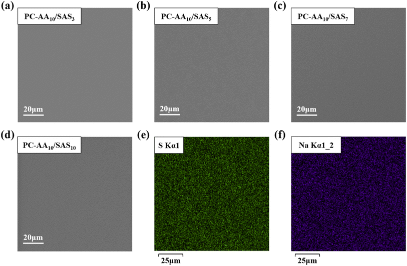 | ||
| Fig. 7 SEM images of PC surface coatings (a) PC-AA10/SAS3; (b) PC-AA10/SAS5; (c) PC-AA10/SAS7; (d) PC-AA10/SAS10; EDS images of PC-AA10/SAS5 (e) S; (f) Na. | ||
Table 4 summarizes the coating hardness obtained through pencil testing, and Fig. S6† shows optical photographs of the coated surfaces after testing. The results indicate that the scratch hardness of the coatings follows a consistent trend with the composition of p(AA-co-SAS) structural units. Specifically, as the proportion of SAS structural units increases, the scratch hardness of the coatings also increases. Xu et al. also discovered that SAS as a surfactant has the effect of improving the hardness of composite coatings.46
| Sample name | X(SAS)![[thin space (1/6-em)]](https://www.rsc.org/images/entities/char_2009.gif) : :![[thin space (1/6-em)]](https://www.rsc.org/images/entities/char_2009.gif) X(AA) X(AA) |
Scratch hardness |
|---|---|---|
| PC-AA10/SAS3 | 1![[thin space (1/6-em)]](https://www.rsc.org/images/entities/char_2009.gif) : :![[thin space (1/6-em)]](https://www.rsc.org/images/entities/char_2009.gif) 8.06 8.06 |
2B |
| PC-AA10/SAS5 | 1![[thin space (1/6-em)]](https://www.rsc.org/images/entities/char_2009.gif) : :![[thin space (1/6-em)]](https://www.rsc.org/images/entities/char_2009.gif) 2.46 2.46 |
HB |
| PC-AA10/SAS7 | 1![[thin space (1/6-em)]](https://www.rsc.org/images/entities/char_2009.gif) : :![[thin space (1/6-em)]](https://www.rsc.org/images/entities/char_2009.gif) 2.40 2.40 |
H |
| PC-AA10/SAS10 | 1![[thin space (1/6-em)]](https://www.rsc.org/images/entities/char_2009.gif) : :![[thin space (1/6-em)]](https://www.rsc.org/images/entities/char_2009.gif) 2.77 2.77 |
B |
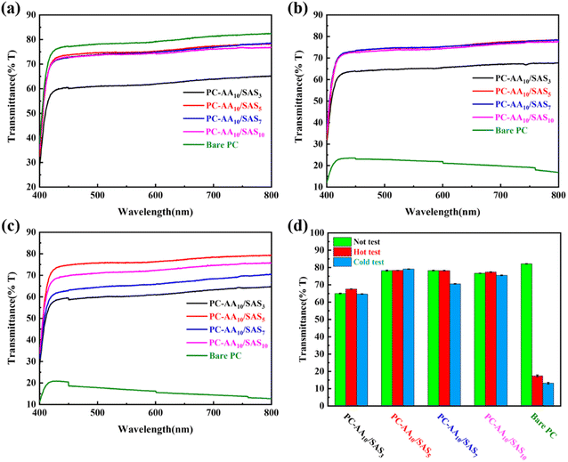
Fig. 8(a) illustrates the total transmittance of all samples under ambient conditions (25 °C, 50% RH). The results are summarized in Fig. 8(d), where bare PC exhibited a transmittance of 82%, while PC-AA10/SAS3 demonstrated the lowest transmittance value of only 65%. Increasing the SAS mass fraction initially leads to an increase followed by a decrease in sample transmittance. The transmittance of PC-AA10/SAS5, PC-AA10/SAS7, and PC-AA10/SAS10 were 78%, 78.5% and 76.5%, respectively.
To evaluate the effectiveness of anti-fogging and frost-resisting abilities, bare PC and PC-AAm/SASn were placed 10 cm above an 80 °C water bath for 15 seconds or exposed to a −25 °C refrigerator for 30 minutes before being tested under ambient conditions (25 °C, 50% RH). Fig. 8(b) shows the transmittance results of anti-fogging tests. The transmittance of bare PC decreased drastically from 82% to 17%. However, PC-AA10/SAS5, PC-AA10/SAS7, and PC-AA10/SAS10 maintained a transmittance of 79%. This indicates that higher SAS content improved the anti-fogging ability of the coating. The optimal SAS content for anti-fogging was determined to be 5%.
Fig. 8(c) shows the transmittance results of frost-resisting tests. The transmittance of bare PC decreased to 13% after testing. On the other hand, PC-AA10/SAS3, PC-AA10/SAS5, PC-AA10/SAS7, and PC-AA10/SAS10 displayed transmittance levels of 65%, 79%, 70%, and 76%, respectively. Thus, an increased SAS content improved the coating's frost-resisting ability, with the optimal SAS content being 5%. Considering the transmittance under different conditions, including ambient, high-temperature and high-humidity, as well as low-temperature and freezing environments, PC-AA10/SAS5 was identified as the optimal sample. Therefore, for subsequent universal and cycle testing, AA10/SAS5 was applied to the surfaces of various substrates.
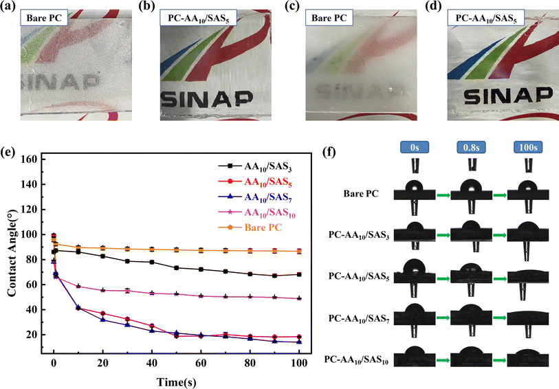
Fig. 9(a)–(d) depicts a comparison between the bare PC and the PC-AA10/SAS5 after conducting anti-fogging and frost-resisting tests. This comparison effectively showcases the outstanding anti-fogging and frost-resisting performance of the AA10/SAS5. Under both test conditions, it is evident that the bare PC rapidly fogs up, whereas the PC-AA10/SAS5 maintains clarity throughout the tests.
The anti-fogging mechanism of hydrophilic coating is to spread water droplets into a water film.12,47 Therefore, the contact angle of the coating was analyzed using a contact angle tester, and Fig. 9(e) shows the relationship between the contact angle of the coating and time. Fig. S7† represents the surface area of a liquid droplet calculated by the test software Avantage, with a volume of 5 μL. The contact angle of Bare PC at 0 s is 97.5°, which decreased to 88.7° after 100 s. From the trend of the graph, it can be observed that the diffusion rate of the coated PC has significant differences. PC-AA10/SAS5 and PC-AA10/SAS7 have the fastest diffusion rate, followed by PC-AA10/SAS10 and PC-AA10/SAS3, which have the slowest diffusion rate. Through analysis and comparison, it was found that the diffusion speed of water droplets on the coating is positively correlated with the proportion of SAS structural units in p(AA-co-SAS). A higher proportion indicates better spreading performance of water droplets. The contact angle of PC-AA10/SAS3 decreased from 86.6° at 0 s to 68.3° after 100 s. The contact angle of PC-AA10/SAS10 decreased from 79.1° at 0 s to 48.7° after 100 s. The overall best-performing PC-AA10/SAS5 had a contact angle of 100.1° at 0 s, which rapidly decreased to 40.1° after 10 s and further decreased to 18.8° after 50 s. Therefore, its outstanding anti-fogging and frost-resisting properties are mainly due to its supreme wetting ability, which can quickly disperse water droplets into a water film within a short time, reducing the refraction and scattering of light, thus achieving high light transmittance of the transparent optical materials. At the same time, the moisture absorption capacity of the coating also contributes to its anti-fogging and frost-resisting properties. The diffusion trend of PC-AA10/SAS7 generally reflects that of PC-AA10/SAS5. Within the same period of time, a faster droplet diffusion rate means a larger droplet spreading area in the same time. Fig. S7† reflects this pattern of variation.
The above results indicate that the content of SAS determines the wetting performance of the coating. Both excessively high and low content can lead to a decrease in water droplet spreading speed. Fig. 9(f) shows the contact angle test images of bare PC and PC-AAm/SASn. The time points of the images are 0, 0.8, and 100 seconds, reflecting the wetting process of all samples intuitively.
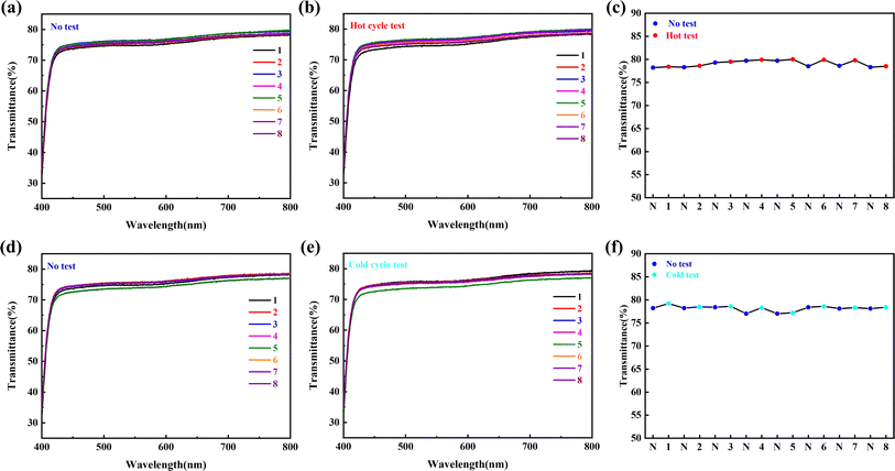
To test the long-term and repeated stability of the coating's performance in high humidity and freezing environments, anti-fogging and frost-resisting cyclic tests were conducted. The results are presented in Fig. 10. Both the anti-fogging (Fig. 10(a)) and frost-resisting (Fig. 10(b)) cyclic tests showed that the PC-AA10/SAS5 exhibited excellent optical performance, with the logo clearly visible behind the coating. Fig. 11 illustrates the changes in transmittance of the coating during the cyclic tests. The coordinates on the axis represent the number of tests, with “N” indicating untested. In the anti-fogging cyclic test, the transmittance of the coating remained between 78.4% and 79.9%, with a maximum deviation of only 1.5%. In the frost-resisting cyclic test, the transmittance of the coating remained between 77.2% and 79.2%, with a maximum deviation of only 2.0%. The test results demonstrate that PC-AA10/SAS5 exhibits excellent cyclic stability and can withstand the challenges of high humidity and freezing environments for an extended period of time.
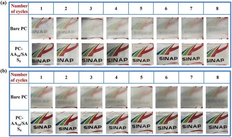 | ||
| Fig. 10 Images of anti-fogging and frost-resisting cycle tests: (a) anti-fogging cycle tests; (b) frost-resisting cycle tests. | ||
The interfacial adhesion of the polymer coating was tested using a tape peel experiment, which is widely applied to study coating adhesion. Adhesion is a critical indicator of coating durability, and ASTM D3359 provides grades ranging from 5B down to 0B, with 5B being the highest level of tape peel test. AA10/SAS5 exhibited a 5B level of adhesion on the PC surface, as observed in the optical microscope images taken before and after the tape peel test (Fig. 12). The polymer coating remained intact after the test, indicating proper adhesion between the coating and the PC substrate.
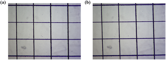 | ||
| Fig. 12 Optical microscope photographs before and after tape peeling test: (a) before test; (b) after test. | ||
The PC-AA10/SAS5 sample was subjected to a friction resistance test by placing it between a 100 g weight and a 1000-grit sandpaper. The sample was pulled with a distance of 20 cm at a speed of 2 cm s−1. After conducting 10 tests, only a few scratches were detected on the surface of the coating. However, after 15 tests, a substantial number of scratches became visible. This indicates that the polymer coating possesses a degree of scratch resistance. The optical microscope images illustrating the results of the scratch test can be found in Fig. S8.†
With a view to investigating the versatility of the AA10/SAS5 coatings, which exhibit the best overall performance, they were applied onto PET film and glass surfaces to test their anti-fogging and frost-resisting properties. As illustrated in Fig. S9(a)–(c),† the transmittance of uncoated PET and coated PET under ambient conditions was determined to be 75.1% and 75.8%, respectively. Subsequent to the anti-fogging test, the transmittance of uncoated PET decreased significantly to 37.1%, while that of coated PET remained relatively stable at 76.5%. Following the frost-resisting test, the transmittance of uncoated PET experienced a slight reduction, whereas coated PET sustained its clarity with a transmittance of 78.1%. In both scenarios, the presence of the logo on the back of the coated PET was clearly discernible (Fig. 13(a) and (b)). Similarly, for glass samples (Fig. S10(a)–(c)†), the transmittance under ambient conditions was determined to be 85.3% for both uncoated and coated glass. Post anti-fogging test, the transmittance of uncoated glass dropped to 39.9%, whereas the coated glass still retained 85.7% transmittance. Subsequent frost-resisting test resulted in a transmittance decline of uncoated glass to 63.5%, while the coated glass maintained a transmittance of 85.2%. Clear visibility was maintained by the coated glass throughout the testing conditions (Fig. 13(c) and (d)). These experimental outcomes confirm that the coating does not impact the transmittance characteristics of the substrate under ambient conditions, as the transmittance of the coated samples remained similar to that of the substrate. Moreover, the coated samples exhibited good transmittance even after undergoing the tests, thereby establishing their exceptional anti-fogging and frost-resisting properties. Furthermore, the coating was successfully applied to a pair of PMMA goggles, resulting in a clear coated section and a heavily fogged uncoated section (Fig. 13(e) and (f)). Even after a year in an indoor environment, the goggles still show good performance, proving that the coating has good long-term resistance and environmental stability (Fig. S11†). These findings emphasize the exceptional versatility of the AA10/SAS5 coating, thereby enabling its application on a wide range of polar surfaces for effective anti-fogging and frost-resisting purposes.
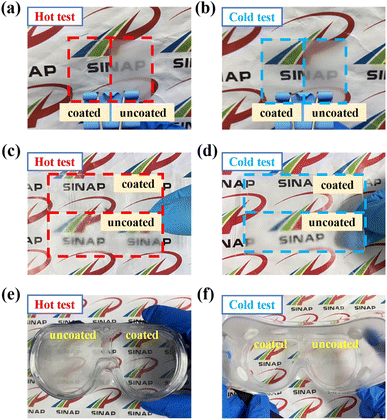 | ||
| Fig. 13 Anti-fogging and frost-resisting test images: (a and b) PET; (c and d) glass; (e and f) PMMA goggles. | ||
4 Conclusion
We have successfully developed an anti-fogging coating using radiation polymerization based on the random copolymer p(AA-co-SAS). In this random copolymer, SAS serves two essential functions. Firstly, it reduces the polymer's number-average molecular weight, thereby weakening intermolecular entanglement. Secondly, it enhances the hydration capability of the random copolymer due to its structural units. As a result, the solubility of the random copolymer in water significantly increases, transforming it from a gel state into a polymer solution suitable for coating applications after radiation polymerization. Additionally, the AA structural units contribute to improved film-forming performance of the coating. Our research findings show that the scratch hardness and wettability of the coating are directly proportional to the content of SAS structural units in p(AA-co-SAS). Among the anti-fogging and frost-resisting tests, AA10/SAS5 exhibits outstanding optical performance. It also demonstrates good cycling stability during repeated testing. Tape adhesion tests reveal that the coating strongly adheres to PC with a 5B level. Moreover, the coating exhibits a certain degree of scratch resistance. Upon applying AA10/SAS5 to surfaces such as PET film, glass, and PMMA goggles, the coated samples exhibit excellent fogging and frost resistance properties. Remarkably, the PMMA goggles maintain stable performance even after one year of indoor exposure. These results confirm the coating's versatility and long-term environmental stability. In conclusion, the developed coating has significant potential application value in industries such as packaging, medical equipment, and transportation that require fog resistance and frost protection.Conflicts of interest
There are no conflicts of interest to declare.Acknowledgements
This work was supported financially by the Gansu Natural Science Foundation (project no. 20JR10RA777).References
- D. Beysens, The formation of dew, Atmos. Res., 1995, 39(1–3), 215–237 CrossRef CAS.
- N. Agam and P. R. Berliner, Dew formation and water vapor adsorption in semi-arid environments - A review, J. Arid Environ., 2006, 65(4), 572–590 CrossRef.
- B. J. Briscof and K. P. Galvin, The effect of surface fog on the transmittance of light, Sol. Energy, 1991, 46(4), 191–197 CrossRef.
- K. Oguri, et al., Misting-free diamond surface created by sheet electron beam irradiation, J. Mater. Res., 2001, 16(2), 553–557 CrossRef CAS.
- I. R. Duran and G. Laroche, Current trends, challenges, and perspectives of anti-fogging technology: surface and material design, fabrication strategies, and beyond, Prog. Mater. Sci., 2019, 99, 106–186 CrossRef.
- X. Xu, et al., A robust and transparent hydrogel coating for sustainable antifogging with excellent self-cleaning and self-healing ability, Chem. Eng. J., 2023, 451, 137879 CrossRef CAS.
- G. Zhou, J. He and L. Xu, Antifogging antireflective coatings on Fresnel lenses by integrating solid and mesoporous silica nanoparticles, Microporous Mesoporous Mater., 2013, 176, 41–47 CrossRef CAS.
- L. Zhang, et al., Mechanically stable antireflection and antifogging coatings fabricated by the layer-by-layer deposition process and postcalcination, Langmuir, 2008, 24(19), 10851–10857 CrossRef CAS PubMed.
- L. Introzzi, et al., "Wetting Enhancer" Pullulan Coating for Antifog Packaging Applications, ACS Appl. Mater. Interfaces, 2012, 4(7), 3692–3700 CrossRef CAS PubMed.
- L. J. Wei, et al., Fabrication and Characterization of Polyglycerol Fatty Acid Esters/Polyethylene Antifogging Film, J. Food Process Eng., 2017, 40(2), e12420 CrossRef.
- S. Ren, et al., Recent progress in synthesis of antifogging agents and their application to agricultural films: a review, J. Coat. Technol. Res., 2018, 15(3), 445–455 CrossRef CAS.
- B. Mansoor, et al., Polyvinyl alcohol (PVA) based super-hydrophilic anti-fogging layer assisted by plasma spraying for low density polyethylene (LDPE) greenhouse films, Prog. Org. Coat., 2021, 159, 106412 CrossRef CAS.
- J. Yoon, et al., Wet-Style Superhydrophobic Antifogging Coatings for Optical Sensors, Adv. Mater., 2020, 32(34), 2002710 CrossRef CAS PubMed.
- Z. Sun, et al., Fly-Eye Inspired Superhydrophobic Anti-Fogging Inorganic Nanostructures, Small, 2014, 10(15), 3001–3006 CrossRef CAS PubMed.
- M. Choi, et al., Superhydrophilic coatings with intricate nanostructure based on biotic materials for antifogging and antibiofouling applications, Chem. Eng. J., 2017, 309, 463–470 CrossRef CAS.
- F. C. Cebeci, et al., Nanoporosity-driven superhydrophilicity: a means to create multifunctional antifogging coatings, Langmuir, 2006, 22(6), 2856–2862 CrossRef CAS PubMed.
- J. Zhi and L.-Z. Zhang, Durable superhydrophobic surfaces made by intensely connecting a bipolar top layer to the substrate with a middle connecting layer, Sci. Rep., 2017, 7, 9946 CrossRef PubMed.
- J.-H. You, et al., Superhydrophilic and antireflective La(OH)(3)/SiO2-nanorod/nanosphere films, J. Colloid Interface Sci., 2011, 354(1), 373–379 CrossRef CAS PubMed.
- F. Liu, et al., In situ growth of TiO2/SiO2 nanospheres on glass substrates via solution impregnation for antifogging, RSC Adv., 2017, 7(26), 15992–15996 RSC.
- Q. Q. Shang and Y. H. Zhou, Fabrication of transparent superhydrophobic porous silica coating for self-cleaning and anti-fogging, Ceram. Int., 2016, 42(7), 8706–8712 CrossRef CAS.
- J. Yoon, et al., Tailoring the Hydrophilicity for Delayed Condensation Frosting in Antifogging Coatings, ACS Appl. Mater. Interfaces, 2022, 14(30), 35064–35073 CrossRef CAS PubMed.
- H. Yang, et al., Facile preparation of a high-transparency zwitterionic anti-fogging poly (SBMA-co-IA) coating with self-healing property, Prog. Org. Coat., 2022, 165, 106764 CrossRef CAS.
- W. A. Braunecker and K. Matyjaszewski, Controlled/living radical polymerization: features, developments, and perspectives, Prog. Polym. Sci., 2007, 32(1), 93–146 CrossRef CAS.
- J. Chiefari, et al., Living free-radical polymerization by reversible addition-fragmentation chain transfer: the RAFT process, Macromolecules, 1998, 31(16), 5559–5562 CrossRef CAS.
- M. K. Georges, et al., Narrow molecular-weight resins by a free-radical polymerization process, Macromolecules, 1993, 26(11), 2987–2988 CrossRef CAS.
- K. E. Heim, A. R. Tagliaferro and D. J. Bobilya, Flavonoid antioxidants: chemistry, metabolism and structure-activity relationships, J. Nutr. Biochem., 2002, 13(10), 572–584 CrossRef CAS PubMed.
- J. Xu, et al., UV curable stimuli-responsive coatings with antifogging and oil-repellent performances, J. Mater. Chem. A, 2021, 9(46), 26028–26035 RSC.
- J. Zhao, et al., Dual-Functional Antifogging/Antimicrobial Polymer Coating, ACS Appl. Mater. Interfaces, 2016, 8(13), 8737–8742 CrossRef CAS PubMed.
- S. Bai, et al., Antifogging/Antibacterial Coatings Constructed by N-Hydroxyethylacrylamide and Quaternary Ammonium-Containing Copolymers, ACS Appl. Mater. Interfaces, 2020, 12(10), 12305–12316 CrossRef CAS PubMed.
- C. Li, et al., Amphiphilic Antifogging/Anti-Icing Coatings Containing POSS-PDMAEMA-b-PSBMA, ACS Appl. Mater. Interfaces, 2017, 9(27), 22959–22969 CrossRef CAS PubMed.
- B. Liang, et al., Transparent and Scratch-Resistant Antifogging Coatings with Rapid Self-Healing Capability, ACS Appl. Mater. Interfaces, 2019, 11(33), 30300–30307 CrossRef CAS PubMed.
- Y. Kim, et al., Coordination-Driven Surface Zwitteration for Antibacterial and Antifog Applications, Langmuir, 2022, 38(4), 1550–1559 CrossRef CAS PubMed.
- S. M. Badawy and A. M. Dessouki, Cross-linked polyacrylonitrile prepared by radiation-induced polymerization technique, J. Phys. Chem. B, 2003, 107(41), 11273–11279 CrossRef CAS.
- H. Huang and H. Liu, Synthesis of the Raspberry-Like PS/PAN Particles with Anisotropic Properties via Seeded Emulsion Polymerization Initiated by γ-Ray Radiation, J. Polym. Sci., Part A: Polym. Chem., 2010, 48(22), 5198–5205 CrossRef CAS.
- H. Mitomo, et al., Radiation-induced graft-polymerization of poly(3-hydroxybutyrate) and its copolymer, J. Macromol. Sci., Pure Appl. Chem., 1995, 32(3), 429–442 CrossRef.
- Y. Chen, et al., Preparation of polymeric nanocapsules by radiation induced miniemulsion polymerization, Eur. Polym. J., 2007, 43(7), 2848–2855 CrossRef CAS.
- M. Barsbay, et al., RAFT-mediated polymerization and grafting of sodium 4-styrenesulfonate from cellulose initiated via γ-radiation, Polymer, 2009, 50(4), 973–982 CrossRef CAS.
- K. J. Yao and G. W. Zhuo, Synthesis and rheological properties in aqueous-solution of poly(acrylamide-co-sodium allylsulfonate), J. Appl. Polym. Sci., 1992, 44(1), 1–7 CrossRef CAS.
- B. Lyu, et al., Preparation and properties of polymeric surfactants: a potential corrosion inhibitor of carbon steel in acidic medium, J. Ind. Eng. Chem., 2019, 80, 411–424 CrossRef.
- L. Feng, et al., Fabricating an anionic polyacrylamide (APAM) with an anionic block structure for high turbidity water separation and purification, RSC Adv., 2017, 7(46), 28918–28930 RSC.
- A. V. Deshpande and E. B. Namdas, Spectroscopic properties of Na-fluorescein in polyacrylic acid films, J. Photochem. Photobiol., A, 1997, 110(2), 177–182 CrossRef CAS.
- K. Saint-Aubin, et al., Dispersion and Film-Forming Properties of Poly(acrylic acid)-Stabilized Carbon Nanotubes, Langmuir, 2009, 25(22), 13206–13211 CrossRef CAS PubMed.
- Q. Sun, et al., Effective adsorption of ammonium nitrogen by sulfonic-humic acid char and assessment of its recovery for application as nitrogen fertilizer, Sci. Total Environ., 2023, 867, 161591 CrossRef CAS PubMed.
- F. Han, et al., Green preparation of silver nanocluster composite AgNCs@CF-g-PAA and its application: 4-NP catalytic reduction and hydrogen production, RSC Adv., 2023, 13(17), 11807–11816 RSC.
- H. Zheng, et al., Synthesis of anion polyacrylamide under UV initiation and its application in removing dioctyl phthalate from water through flocculation process, Sep. Purif. Technol., 2014, 123, 35–44 CrossRef CAS.
- C. Xu, et al., Mechanical Characteristic Study of High Frequency Pulse Electrodeposited Nanocrystalline Ni-Co Alloy, J. Comput. Theor. Nanosci., 2012, 9(9), 1391–1394 CrossRef CAS.
- W. Zheng, et al., Rational construction of multifunctional hydrophilic coatings with sustainable anti-fogging, UV-shielding and anti-freezing abilities, Chem. Eng. J., 2023, 459, 141605 CrossRef CAS.
Footnote |
| † Electronic supplementary information (ESI) available. See DOI: https://doi.org/10.1039/d3ra08542b |
| This journal is © The Royal Society of Chemistry 2024 |


