DOI:
10.1039/D3RA08256C
(Paper)
RSC Adv., 2024,
14, 8769-8778
Tailoring graphene-oxide and reduced-graphene-oxide with NaNO3 and CaCl2 catalysts with enhanced photo-catalytic degradation of methylene blue dye
Received
3rd December 2023
, Accepted 22nd February 2024
First published on 14th March 2024
Abstract
This study employed various experimental techniques to produce graphene oxide (GO) under different conditions, such as the inclusion or exclusion of NaNO3, and reduced graphene oxide (RGO) with or without the catalyst CaCl2. The procedure of decreasing RGO was carried out using the reducing agent NaBH4. Moreover, the prepared mixtures were utilized in the degradation process of methylene blue (MB) dye using photo-catalysis, with exposure to both ultraviolet (UV) light and sunlight. When exposed to UV and sunlight irradiation, WN-GO showed rapid and ecologically friendly breakdown of MB dye in comparison to N-GO. WN-GO exhibited exceptional adsorption capabilities, surpassing other tested materials like N-GO, WN-C-RGO and C-RGO. Although WN-C-RGO has demonstrated satisfactory performance in terms of photo-catalytic degradation, as the concentration–time graph of the MB dye revealed significant degradation, with a reduction of up to 90% and 62.5% under UV light and sunlight exposure, respectively. These results offer insightful information on the potential of graphene-based materials to address other environmental issues, particularly in the areas of water treatment.
1 Introduction
Photochemical processes possess significant potential for addressing energy and environmental challenges, and likely contribute to the development of a sustainable civilization. Although there have been some recent advancements, the fundamental ability of traditional photocatalysts to catalyze reactions has been greatly limited by various complications, including (i) poor absorption of visible light, (ii) ineffective recombination of electron–hole pairs in the excited state, and (iii) low chemical stability. Researchers are currently engaged in the ongoing development of photocatalysts that has practical applications in the industrial sector. Graphene has attracted considerable scientific attention for enhancing the efficiency of photocatalysts due to its unique optical and electrical properties, as well as its notable surface area, mechanical strength, and photochemical stability.1
The term “graphene” refers to a combination of graphite, which is a crystalline form of carbon, with the suffix “-ene” indicating a two-dimensional structure. Graphite and diamond are both naturally occurring allotropes of carbon, consisting of three-dimensional structures made up of carbon atoms.2 Graphene, in contrast, is a two-dimensional lattice structure that resembles a honeycomb. It is composed of closely packed carbon atoms that create a flat layer with a thickness of only one atom. Graphene's carbon atoms link through sp2 hybridization.2 In order to create a graphite structure that is 1 mm thick, it requires an impressive amount of three million layers of graphene. It is true that a single square meter of graphene weighs only 0.77 milligrams.3,4 (GO) has a structurally stable structure and demonstrates remarkable thermal, electrical, optical, and mechanical conductive qualities.5 Research has demonstrated that GO has a remarkable capacity to sustain a high level of dispersion stability at pH levels over 7. This attribute enables the creation of films with large surface areas.6
Graphene, when arranged into a single layer, has unique electrical properties that result in a surprisingly high level of opacity. It only absorbs 2.3% of white light.7 Graphene exhibits an extremely high tensile strength, exceeding that of steel by a factor of one hundred.8 Graphene's exceptional characteristics make it a highly promising material with significant potential in various applications. These encompass several applications such as sensor technology,9 transparent touch displays, light-emitting panels,10,11 lithium-ion battery technology,12,13 and superhydrophobic coatings.14,15 In 2004, Andre Geim and Konstantin Novoselov successfully isolated graphene layers from graphite using a technique called the scotch tape method or micromechanical cleavage.16 Several methods have been extensively studied for the production of graphene, including as micromechanical exfoliation, epitaxial growth, chemical vapor deposition (CVD), and modified Hummer's technique. Furthermore, there is a need for the advancement of more effective chemical reduction methods in order to facilitate the mass manufacture of graphene with superior conductivity. Out of these methods, the modified Hummer's method has proven to be the most suitable for this purpose. It has advantages such as being cost-effective, producing dependable results, increasing yield, and promoting environmental sustainability.17,18 In addition, the advantages of cost-effectiveness and feasibility in extensive manufacturing further augment the attractiveness of this method. Moreover, the significant results of this study have the capacity to improve the overall excellence of graphene manufacturing, thereby impacting its many uses. Crucially, it has been noted that excluding NaNO3 during the synthesis of GO does not adversely impact the final product's yield. Nevertheless, GO has the benefit of producing eco-friendly graphene oxide, which successfully prevents the emission of hazardous gases (NO2/N2O4) into the atmosphere.19 The excellent water dispersibility, adjustable bandgap, and compatibility at the molecular level of graphene make it a promising candidate for studying its potential as a photocatalytic material.20 Apart from GO, lot of researchers have explored some other photocatalytic material21 such as Mg and chitosan doped SnO2 Quantum dots,22 cellulose nanocrystal grafted poly acrylic acid doped MnO2 nanorods,23 and annealed nickel sulfide quantum dots.24
In this study, we expand upon our previous research, which was published and recognized as a crucial reference in the field.25,26 The current study expands upon the earlier discoveries, diving further into the topic and providing fresh insights into its complexities. The objective of this study is to enhance our comprehension of graphene-based materials and their practical uses by investigating the impact of CaCl2 and NaNO3 on the synthesis of GO and RGO. This work aims to give informative data that can aid in optimizing material synthesis processes, resulting in enhanced performance and customized properties in graphene-based materials for various application domains. We showcase the photocatalytic capabilities of GO nanostructures when exposed to methylene blue (MB), by examining the effectiveness of MB reduction under ultraviolet (UV) light and sunshine. Our main goal is to improve and optimize the treatment of wastewater by using photocatalytic degradation of MB.
2 Materials and methods
The synthesis of GO was carried out using a modified version of the Hummer process.17–19 The mechanism employed in this approach involves a two-step oxidation and exfoliation process, which is subsequently followed by a reduction process to generate RGO. The addition of oxygen-containing functional groups to the carbon atoms in GO during the oxidation stage leads to a reduction in conductivity.7,27–31 The groups encompassed are carboxyl, hydroxyl, epoxy, and carbonyl. A subsequent reduction process is performed to enhance conductivity by decreasing the interlayer distance of the reduced graphene oxide (RGO) through the reduction of oxygen-containing groups. In this research, various experimental procedures were employed to prepare GO, both with and without the presence of NaNO3, as well as RGO, with and without the catalyst CaCl2. The reducing agent NaBH4 was used in the reduction process. Additionally, the concentrations of the constituent chemicals were varied to investigate their influence on the preparation of GO and RGO.
2.1 Methodology to prepare GO with NaNO3·(N-GO) and RGO with CaCl2·(C-RGO)
To synthesize GO, a mixture was prepared by combining 4 g of graphite flakes with 2 g of NaNO3. This mixture was then subjected to the addition of 100 ml of concentrated H2SO4, initiating the oxidation process. To ensure controlled conditions, the mixture was placed in an ice bath and vigorously stirred for a duration of 4–5 hours. The presence of NaNO3 in the mixture facilitated an exothermic reaction that promoted the oxidation of graphite. Following the initial oxidation step, 12 g of KMnO4 was gradually introduced to the mixture while maintaining a temperature range of 20–25 °C, with continuous stirring. Throughout this process, the mixture was kept in the ice bath, and the addition of deionized (DI) water was performed to form a paste-like consistency. Subsequently, the suspension was heated to 98 °C, and a dropwise addition of H2O2 took place to eliminate impurities and bring the reaction to a conclusion. To achieve a neutral pH and obtain NaNO3-assisted graphene oxide (N-GO), subsequent washing with filtration steps were carried out utilizing DI water.31 To synthesize RGO, NaBH4 was utilized as the reducing agent. NaBH4 is particularly effective in reducing C![[double bond, length as m-dash]](https://www.rsc.org/images/entities/char_e001.gif) O species, but less efficient in reducing epoxy groups. Carboxyl and alcohol groups may still be present even after reduction. The resistance of the oxide layer in RGO reduced using NaBH4 is lower compared to RGO reduced using hydrazine (N2H2). NaBH4 serves as a superior reducing agent by donating electrons to other molecules, acting as a source of hydride ions (H−). By reacting with carbonyl and other functional groups containing oxygen, the hydride ions cause the carbon–oxygen bonds to break and subsequently replace them with carbon-hydrogen bonds. As a result, graphene oxide proceeds to reduction and becomes graphene. In graphene, this reduction process results in improved electrical conductivity and other beneficial features.32,33A suspension was created by combining 150 mg of GO with 300 ml of DI water in order to reduce GO, resulting in a concentration of mg ml−1. Subsequently, 3.42 g of NaBH4 was gradually introduced to the suspension at room temperature, allowing the reaction to progress. Any potentially toxic gases produced during the reaction were allowed to evaporate. The solution's colour changed to a steel grey shade after 2.67 g of CaCl2 were added. For 12 hours, the mixture underwent stirring at room temperature to produce reduced graphene oxide (C-RGO). After the reaction was finished, the mixture was filtered and rinsed with DI water until the filtrates' pH reached a neutral level.
O species, but less efficient in reducing epoxy groups. Carboxyl and alcohol groups may still be present even after reduction. The resistance of the oxide layer in RGO reduced using NaBH4 is lower compared to RGO reduced using hydrazine (N2H2). NaBH4 serves as a superior reducing agent by donating electrons to other molecules, acting as a source of hydride ions (H−). By reacting with carbonyl and other functional groups containing oxygen, the hydride ions cause the carbon–oxygen bonds to break and subsequently replace them with carbon-hydrogen bonds. As a result, graphene oxide proceeds to reduction and becomes graphene. In graphene, this reduction process results in improved electrical conductivity and other beneficial features.32,33A suspension was created by combining 150 mg of GO with 300 ml of DI water in order to reduce GO, resulting in a concentration of mg ml−1. Subsequently, 3.42 g of NaBH4 was gradually introduced to the suspension at room temperature, allowing the reaction to progress. Any potentially toxic gases produced during the reaction were allowed to evaporate. The solution's colour changed to a steel grey shade after 2.67 g of CaCl2 were added. For 12 hours, the mixture underwent stirring at room temperature to produce reduced graphene oxide (C-RGO). After the reaction was finished, the mixture was filtered and rinsed with DI water until the filtrates' pH reached a neutral level.
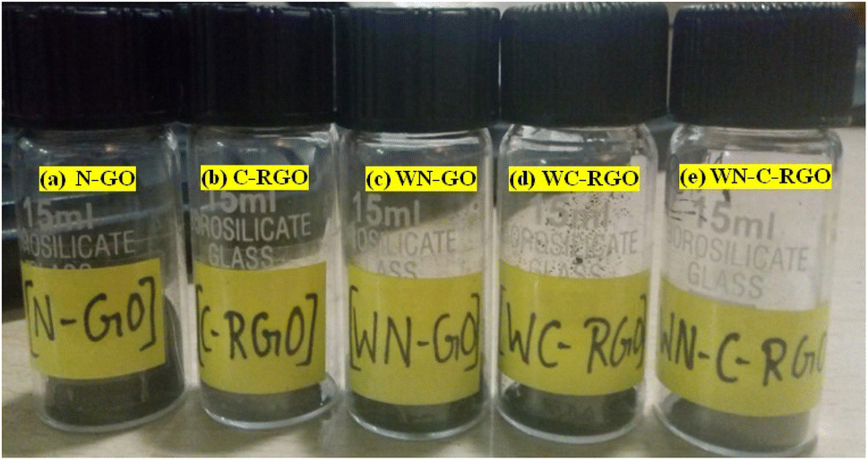
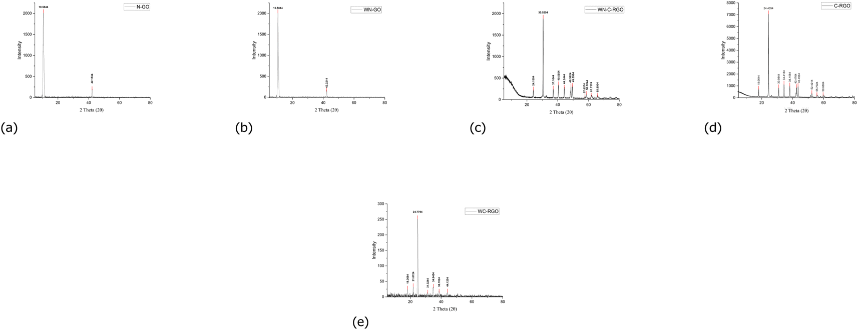
2.2 Methodology to prepare GO without NaNO3 (WN-GO), RGO without CaCl2 (WC-RGO) and with CaCl2 (WN-C-RGO)
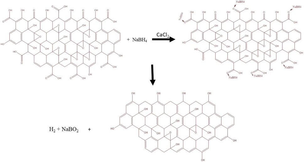
WN-GO is prepared as described in Section 2.2 except using NaNO3. Additionally, in the synthesis process, the concentration of KMnO4 was increased by 1.5 times.19 With the exception of CaCl2, which was not employed in the WC-RGO synthesization process, the reduction process for WC-RGO and WN-C-RGO adhered to the identical methodology as detailed in Section 2.2.34 There are different aspects regarding the synthesis approach that depend on the quality of the obtained GO and RGO, with the best combination of GO and RGO being selected based on the results obtained. As a result, the roles of the oxidizing agent (NaNO3) and catalyst (CaCl2) are currently being investigated. All the synthesized nanoparticles i.e., N-GO, C-RGO, WN-GO, WC-RGO, WN-C-RGO are shown in Fig. 1.CaCl2 was used as a catalyst in the presence of NaBH4 enhances the reducing action of NaBH4 on functional groups containing oxygen in organic synthesis. CaCl2 acts as a catalyst by simplifying the reaction between NaBH4 and the oxygenated functional groups, increasing their reduction. This methodology offers various notable benefits, such as operating under mild reaction temperatures, achieving high reduction yields, and exhibiting environmental sustainability. The pronounced activation effect of this approach is evident through the enhanced production yield and extended reducible species range.35,36 The NaBH4 reagent is postulated to function through a catalytic hydrogenation mechanism. Fig. 2 illustrates a possible reduction mechanism, although it is an oversimplification of the actual reaction. In reality, NaBH4 reacts with de-ionized water to generate hydrogen bubbles.
 |
| | Fig. 1 Synthesized samples of (a) N-GO, (b) C-RGO, (c) WN-GO, (d) WC-RGO, and (e) WN-C-RGO. | |
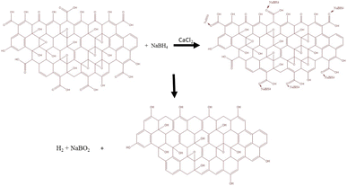 |
| | Fig. 2 Reduction mechanism as per the reaction.34 | |
2.3 Characterization of the samples
Scanning Electron Microscopy (SEM) was conducted using the “SupraTM 55, Sigma” instrument. This SEM instrument allows for the analysis of selected locations on a sample, providing detailed information about surface morphology and topology. To enhance the imaging capabilities and conductivity of the sample, a gold (Au) coating was applied using the “Quorum” of ISORES apparatus. The gold coating helps to improve the resolution and quality of the SEM images, allowing for better visualization and analysis of the sample's surface features. X-Ray diffraction (XRD) [CuKα radiation (λ = 1.5406° A)] was used for structural characterization under operating conditions of 40 Ma and 45 kV. The temperature was maintained at 25 °C, and the measurement range covered 5° to 99° degrees with a step size of 0.0170° (2θ). The functional groups contained in both GO and RGO samples were identified using Fourier Transform Infrared Spectroscopy (FTIR). With regard to both fluid and opaque solid samples, UV-vis spectroscopy was used to examine the transmission or absorption characteristics in the wavelength range of 200–800 nm.
2.4 Analysis of photo-catalytic activity
Under exposure to UV light and sunlight, the photo-catalytic effectiveness of the synthesized graphene samples (N-GO, WN-GO, CRGO, and WN-CRGO) for the degradation of MB dye was examined. To create dye-contaminated aqueous media, 2 mg of the graphene samples were added to a suspension containing 0.015 mg ml−1 of MB in deionized (DI) water. Two separate experiments were simultaneously conducted using graphene oxide samples (N-GO and WN-GO) by dispersing the nano-photo catalysts into the dye-contaminated aqueous media. The GO (N-GO and WN-GO) nanoparticle adsorption equilibrium in the organic solvent was established after these suspensions were magnetically stirred in the dark. The (GO) nanoparticles were evenly distributed throughout the dye media for 20 minutes in order to maximize the interactions between graphene particles and dye molecules.
After 20 minutes of stirring, equilibrated and stable aqueous suspensions were exposed to UV light with a wavelength range of 200–400 nm and sunlight at a temperature of 35 degrees celsius. This exposure took place for a total duration of 160 minutes within a custom-made laboratory photo reactor. Under the same experimental circumstances, both reactions were carried out concurrently. The reaction mixtures were continuously stirred in glass beakers and exposed to UV and sunshine without the use of any additional external light sources. In order to track the deterioration of the MB solution in N-GO and WN-GO during the irradiation procedure, the spectra of the aqueous suspension were periodically recorded every 20 minutes using a UV-vis spectrometer.
3 Result and discussion
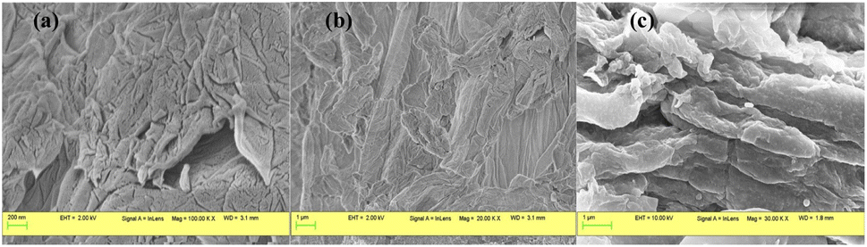
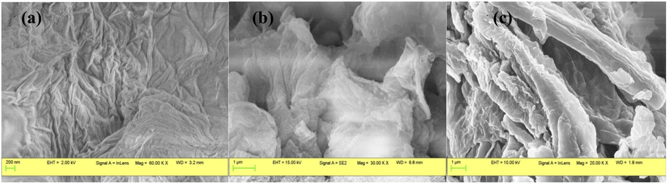
The surface morphology of graphene oxide (GO) and reduced graphene oxide (RGO) was analyzed using scanning electron microscopy (SEM), as depicted in Fig. 3 and 4 respectively. Fig. 3(a and b) exhibit SEM micrographs of N-GO, showcasing a relatively smooth and flat surface with larger lateral dimensions compared to C-RGO. On the other hand, Fig. 3(c) displays SEM images of C-RGO, revealing the presence of imperfections, crystal breakage, and non-uniform layers attributed to the greater reduction of oxygen-containing functional groups. Conversely, the appearance of fewer defects and increased brightness is observed in WN-GO due to the presence of oxygenated functional groups (refer to Fig. 4). The RGO has wrinkled and transparent sheets with folded edges, obtained through the exfoliation of bulk graphite layers (WN-GO) material into individual and separated (WC-RGO and WN-C-RGO) layers. The reduction process of WN-GO resulted in an increase in the surface roughness of graphene sheets due to substantial atomic rearrangement.15 Agglomeration of WN-C-RGO was observed due to its limited dispersibility after reduction. SEM images revealed bright edges in WN-GO, indicating partial amorphousness of WN-GO with residual graphitic crystalline structures.16,17 These formed layers exhibited non-uniformity, which could potentially impact the conductivity and transparency of the material. Overall, the SEM analysis confirmed that the obtained results possessed characteristic features of graphene and hold potential for further applications.
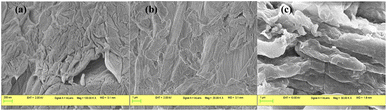 |
| | Fig. 3 SEM images of N- GO nanosheets, (a) magnification of 100.00 K.X at 200 nm (b) 20.00 KX at 1 μm and SEM images of C-RGO (c) 30.00 KX at 1 μm. | |
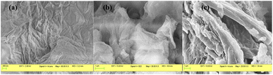 |
| | Fig. 4 SEM images of (a) WN-GO nanosheets with magnification 60.00 K.X at 200 nm (b) WC-RGO with magnification 30.00 K.X at 1 μm (c) WC-RGO with magnification 20.00 KX at 1 μm. | |
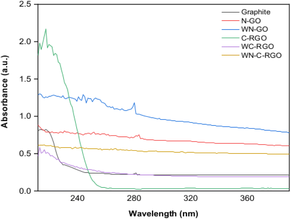
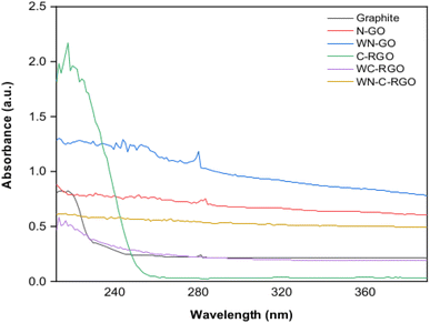
The UV-vis spectra (refer Fig. 5) showed that the absorption peak for graphite, N-GO, and WN-GO suspension appeared at wavelengths of 231.2 nm, 216.8 nm, and 212.0 nm, respectively. As the samples transitioned from graphite to N-GO and WN-GO, the λmax decreased by 6.23% and 8.3%, respectively, while absorbance increased by 33.88% and 37.14%, respectively.
 |
| | Fig. 5 UV-vis spectra of graphite, N-GO, C-RGO, WN-GO, WC-RGO and WN-C-RGO. | |
The inclusion of NaNO3 in N-GO led to an upward shift in the peak wavelength (λmax) and a decrease in absorption compared to WN-GO. The reduction process utilizing NaBH4 with a catalyst induced a red shift in the absorption peak and an increase in λmax for the RGO samples, indicating the restoration of electronic conjugation within the graphene sheets. The presence of weak peaks around 300 nm in the RGO spectra was attributed to the n to π* transition of the carbonyl group. The peak maxima for the π to π* transition and their corresponding absorbance values for both GO and RGO are summarized in Table 1.
Table 1 UV-vis results for GO and RGO samples
| Sample code |
Graphite (G) |
N-GO |
C-RGO |
WN-GO |
WC-RGO |
WN-C-RGO |
| Peak wavelength (nm) |
231.2 |
216.8 |
293.6 |
212.0 |
256.4 |
260.0 |
| Absorbance (a.u.) |
0.735 |
0.984 |
0.571 |
1.008 |
0.848 |
0.920 |
The weak peaks observed at 300 nm in the spectra of RGO can be attributed to the n to π* transition of the carbonyl group. This can be explained by considering the electronic transitions that occur in graphene-based materials. GO serves as a precursor to RGO by incorporating oxygen-containing functional groups onto the graphene lattice, including hydroxyl, epoxy, and carbonyl groups. These functional groups introduce additional electronic states onto the graphene structure, hence impacting its electronic band structure and optical characteristics. The n to π* transition involves the transfer of an electron from a non-bonding orbital (n) to an antibonding π* orbital. Regarding GO, the carbonyl group (CO) usually consists of an electron pair that is not involved in bonding. When this electron pair transitions to the antibonding π* orbital, it can lead to the absorption of light at approximately 300 nm.
The reason for the observed peak maxima and absorbance values in the π to π* transition for both Graphene Oxide (GO) and Reduced Graphene Oxide (RGO) can be traced to alterations in the electronic structure due to reduction.37
3.1 X-ray diffraction (XRD) of N-GO and C-RGO
The crystal phase and interlayer spacing of GO (N-GO and WN-GO), and RGO (C-RGO, WC-RGO, and WN-C-RGO) were examined by XRD analysis. Fig. 6 displays the XRD spectra of GO, and RGO. A single distinct peak is visible at an angle of 10.61445° and 10.61511°, denoted as 2θ, in the case of NGO and WN-GO respectively as shown in Fig. 6(a and b). The presence of a well-arranged layer structure with FWHM of 0.60905 and 0.63694 has been confirmed by these peaks of both. This increase was caused by the insertion of oxide functional groups, such as epoxy, hydroxyl, carbonyl, and carboxyl groups, into the carbon basal plane during a chemical oxidation reaction. Consequently, the distance between successive carbon layers has increased. Following the chemical reduction process, the presence of oxygen-containing functional groups was greatly reduced. During the reduction process, the oxygen functional groups are removed, resulting in the restoration of the sp2 carbon network characteristic of graphene. The removal of these functional groups facilitates increased stacking of graphene sheets, leading to the growth of larger graphene domains or crystals.29
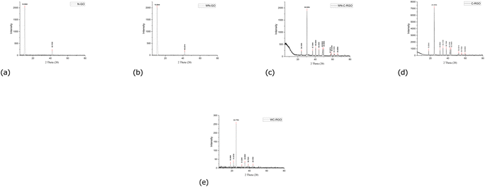 |
| | Fig. 6 XRD spectra of GO and RGO (a) N-GO (b) WN-GO (c) WN-C-RGO (d) C-RGO (e) WC-RGO. | |
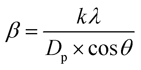
In this study, it has been critically revealed that, according to Scherrer's broadening formula, the broadening of powder diffraction is inversely proportional to the crystallite size (as per eqn (1)).
| |
 | (1) |
As a result, a wider peak is observed for C-RGO, WC-RGO, and WN-C-RGO at an angle of 2θ at 24.41852°, 24.78754° and 30.50462° respectively as shown in Fig. 6(c–e). This suggests that the π-conjugated structure of graphene has been significantly repaired in the resulting RGO. The inadequate organization may be attributed to the creation of a limited number of layers of RGO after the reduction of GO. Furthermore, it was discovered that the thin RGO nanosheets were arranged in a stacked configuration, forming a thick layered structure. This arrangement was attributed to the presence of robust van der Waals interactions between each layer. Table 2 displays the characteristic values obtained through the application of Scherrer's equation, along with the distinctive features, for the graphene samples.
Table 2 Average crystallite size and percentage crystallinity of GO (N-GO and WN-GO), and RGO (C-RGO, WC-RGO, and WN-C-RGO) examined by XRD analysis
| Material |
FWHM |
2θ |
Crystalite size |
Percentage crystallinity |
| N-GO |
0.60905 |
10.61445 |
13.0999 |
38.85 |
| WN-GO |
0.63694 |
10.61511 |
12.52629 |
43.28 |
| C-RGO |
0.16733 |
24.41852 |
48.57547 |
19.29 |
| WC-RGO |
0.40007 |
24.78754 |
20.33105 |
20.92 |
| WN-C-RGO |
0.24578 |
30.50462 |
33.50284 |
11.33 |
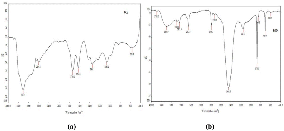
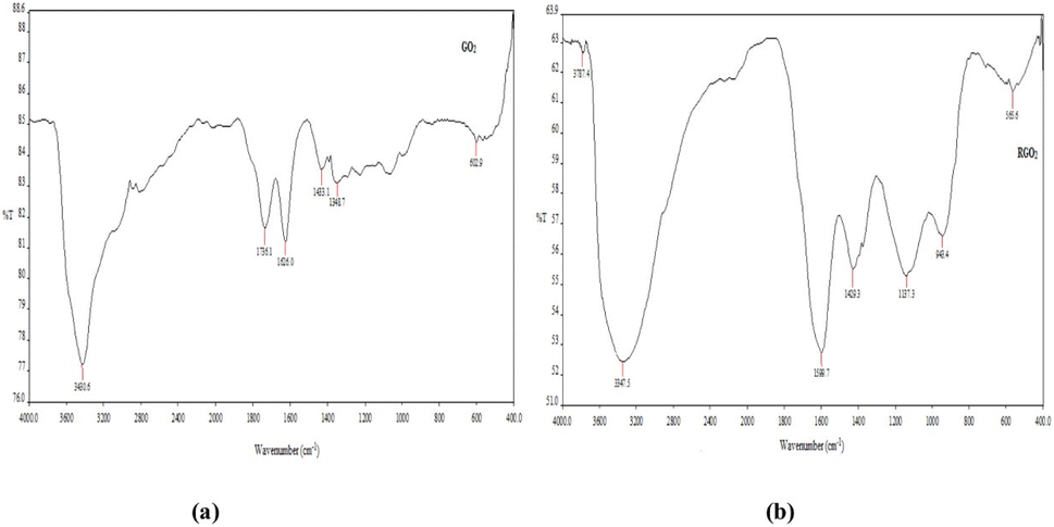
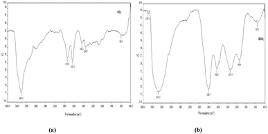
The Fourier Transform Infrared (FTIR) spectra of N-GO (see Fig. 7) exhibited characteristic peaks at 3417 cm−1, 1734 cm−1, 1624 cm−1, and 1349 cm−1, corresponding to OH stretching, CO stretching, CC stretching, and C–O–C bending, respectively. In the case of C-RGO, peaks were observed at 3399 cm−1, 1795 cm−1, and 1157 cm−1, confirming the presence of functional groups associated with OH stretching, CO stretching, and C–O – C bending, respectively. The positions of the peaks related to C–O–C, CC, and CO in C-RGO exhibited shifts, accompanied by relatively reduced intensities. An intense peak at 1448 cm−1 was evident in C-RGO, indicating C–H bending in methyl CH3 and CH2 groups. Notably, the intense peak at 1624 cm−1 observed in N-GO, which represented CC stretching, disappeared in C-RGO, providing strong evidence of reduction. These results unequivocally demonstrate the successful reduction of C-RGO in comparison to N-GO.
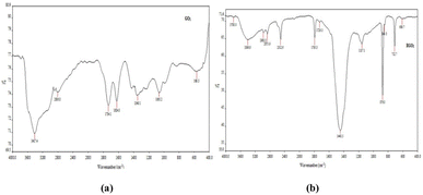 |
| | Fig. 7 FTIR spectra of (a) N-GO and (b) C-RGO. | |
The Fourier-transform infrared (FTIR) spectra of WN-GO (see Fig. 8) exhibited well-defined and prominent peaks at specific wavenumbers, indicating distinct molecular vibrations. The peaks observed at 3430 cm−1, 1736 cm−1, 1626 cm−1, 1433 cm−1, and 1348 cm−1 corresponded to various molecular functionalities. The peak at 3430 cm−1 represented the stretching of hydroxyl (OH) groups, while the peak at 1736 cm−1 indicated the stretching of carbonyl (CO) groups. The peak observed at 1626 cm−1 was attributed to the stretching of carbon–carbon (CC) bonds, whereas the peak at 1433 cm−1 suggested the bending of carbon-hydrogen (C–H) bonds. Finally, the peak at 1348 cm−1 corresponded to the stretching of carbon-oxygen-carbon (C–O–C) bonds. Similarly, in the case of WC-RGO, specific peaks were observed in the FTIR spectra. These peaks were observed at 3347 cm−1, 1599 cm−1, 1429 cm−1, and 1137 cm−1, confirming the presence of particular functional groups. The peak at 3347 cm−1 indicated the stretching of hydroxyl (OH) groups, while the peak at 1599 cm−1 represented the stretching of carbon–carbon (CC) bonds. The peak observed at 1429 cm−1 indicated the bending of carbon-hydrogen (C–H) bonds, and the peak at 1137 cm−1 corresponded to the stretching of carbon-oxygen-carbon (C–O–C) bonds.It is worth mentioning that in the reduced graphene oxide (RGO), the peak positions associated with carbon-oxygen-carbon (C–O–C), carbon–carbon (CC), hydroxyl (OH), and carbonyl (CO) groups exhibited shifts in comparison to the spectra of the original graphene oxide. Additionally, the intensities of these peaks were comparatively reduced in the RGO samples. Tables 3 and 4 displays the observed functional groups present in the graphene samples (Fig. 9).
 |
| | Fig. 8 FTIR spectra of (a) WN-GO and (b) WC-RGO. | |
Table 3 FTIR characteristics of N-GO and C-RGO represented by wavenumber (cm−1) versus transmittance (%)
| N-GO |
C-RGO |
| Wave number (cm−1) |
Assignment |
Transmittance (%) |
Wave number (cm−1) |
Assignment |
Transmittance (%) |
| 3417 |
OH stretching |
70.8 |
3399 |
OH stretching |
65.0 |
| 1734 |
CO stretching |
73.1 |
1795 |
CO stretching |
64.9 |
| 1624 |
CC stretching |
73.4 |
1448 |
CH bending |
38.2 |
| 1349 |
C–O–C stretching |
73.9 |
1157 |
C–O–C stretching |
63.9 |
Table 4 FTIR characteristics of WN-GO and WC-RGO represented by wavenumber (cm−1) versus transmittance (%)
| WN-GO |
WC-RGO |
| Wave number (cm−1) |
Assignment |
Transmittance (%) |
Wave number (cm−1) |
Assignment |
Transmittance (%) |
| 3430 |
OH stretching |
77.2 |
3347 |
OH stretching |
65.0 |
| 1736 |
CO stretching |
81.8 |
1599 |
CO stretching |
64.9 |
| 1626 |
CC stretching |
81.3 |
1429 |
C–H bending |
38.2 |
| 1433 |
C–H bending |
83.5 |
|
|
|
| 1349 |
C–O–C stretching |
83.0 |
1137 |
C–O–C stretching |
63.9 |
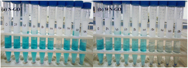 |
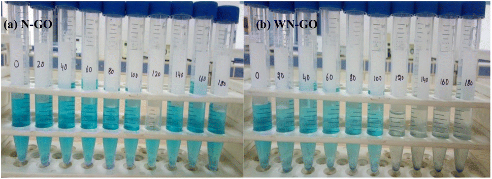
| | Fig. 9 Photographic representations of the aqueous suspension of methylene blue (MB) dye are depicted for (a) N-GO and (b) WN-GO samples (from 0 to 180 min). | |
4 Comparative analysis of photodegradation and decolorization of methylene blue dye using N-GO and WN-GO nanostructures
Methylene blue, a cationic and synthetic dye, possesses a cross-conjugated structure with the chemical formula C16H18CN3S. It comprises a carbon–carbon (C–C) double bond in conjunction with two carbon–oxygen (C–O) acceptor groups and two nitrogen–hydrogen (N–H) donor groups.17 The characteristic absorption peaks were observed at 667 nm and 703 nm for WN-GO and N-GO, respectively, indicating π to π* transitions, while the shoulder peaks represented n to π* transitions. Under UV light irradiation, the GO photocatalysts undergo excitation, causing electrons to move from the valence band to the conduction band and generating electron–hole pairs as shown in eqn (2). These carriers then migrate to the material's surface, forming photocatalytic active centers. The high oxidative potential of the holes leads to their reaction with H2O molecules in the nanomaterial suspension, resulting in the formation of hydroxyl radicals, as shown in eqn (3) and (4).| | |
GO + hν → GO + e− + h+
| (2) |
Furthermore, the electrons present in the conduction band on the surface of graphene oxide (GO) possess the capability to catalytically reduce molecular oxygen, resulting in the generation of superoxide anions. These superoxide anions then react with H2O, resulting in the formation of H2O2 as evident from eqn (5) and (6), which further generates OH radicals.
Hence, it is the electrons in the conduction band that play a crucial role in the generation of hydroxyl radicals, which serve as the primary agents for the mineralization of organic matter.
| | |
OH−/O2− + MBdye → CO2 + H2O + Degraded Product (DP)
| (7) |
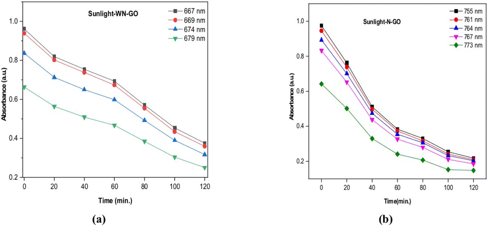
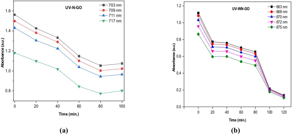
The time-dependent reduction of methylene blue (MB) dye by N-GO and WN-GO, along with their respective intensities, is depicted in Fig. 10 and 11, under sunlight and UV exposure, respectively. The absorption spectra at specific wavelengths (λ = 667 nm and 703 nm) were evaluated to determine the degradation, which increased with longer exposure times (from 0 to 30 minutes). The optimal absorption peak consistently decreased as exposure time increased (from 0 to 120 minutes), indicating successful photocatalytic degradation during sunlight and UV light exposure.Fig. 10(a and b) illustrates the reduction of the MB mixture by N-GO and WN-GO under sunlight exposure, accompanied by a concurrent decrease in intensity. The observed spectroscopic changes in MB intensity using WN-GO indicate faster degradation compared to N-GO, attributed to the presence of more active sites. The reduction in MB intensity by both N-GO and WN-GO during 0–120 minutes of exposure can be ascribed to the formation of photo-catalytic active centres and the generation of hydroxyl radicals, as mentioned earlier. Similarly, Fig. 11(a and b) shows a similar trend under UV exposure, emphasizing the reduction of the MB mixture by N-GO and WN-GO, accompanied by a significant decrease in MB intensity.The faster degradation of MB by WN-GO can be accredited to its smaller size and higher surface area, which facilitates better adsorption and greater availability of active sites. The results indicate that WN-GO have good photo-catalytic activity as compared to other samples that shows partial degradation. The conclusion can be drawn that WN-GO has the potential to be used for the degradation of organic pollutants in wastewater treatment.The decolorization rate of the target contaminant was determined by analyzing the optical absorption spectra. The degradation efficiency (η) was calculated using the following equation:34,35
| |
 | (8) |
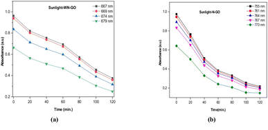 |
| | Fig. 10 Absorbance of methylene blue with respect to time via N-GO (a), WN-GO (b) under sunlight exposure. | |
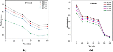 |
| | Fig. 11 Absorbance of methylene blue with respect to time via N-GO (a), WN-GO (b) under UV light. | |
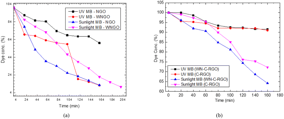
Further experimentation revealed that there is incredible potential to display the removal efficiency of other prepared graphene samples like CRGO and WN-C-RGO. Thus, a comprehensive comparison of all graphene samples, highlighting their performance under both sunlight and UV-light exposure condition as shown in Fig. 12(a and b). Through extended photocatalysis, an impressive removal efficiency of above 90% was achieved within a more prolonged period of 204 minutes by WN-GO (Fig. 12(a)). Additionally, the utilization of WN-C-RGO as an alternative photocatalyst also demonstrated notable efficacy in the degradation process, resulting in the removal of approximately 45% of the dye compound (Fig. 12(b)). Despite exhibiting a lower percentage of degradation compared to WN-GO, WN-C-RGO still exhibited commendable performance in terms of photocatalytic degradation.These results display the effectiveness of prolonged photocatalytic treatment in significantly augmenting the degradation performance, resulting in the remarkable removal of methylene blue from the system. The provided excerpt pertains to the outcomes of an experimental investigation conducted to assess the efficacy of photocatalysis for the removal of methylene blue, a dye compound, from a given system. Subsequent experimentation was undertaken to explore the potential for further optimizing the removal efficiency.38,39
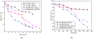 |
| | Fig. 12 Photocatalysis removal efficiency of NGO and WN-GO (a), C-RGO and WN-C-RGO (b). | |
4.1 Mechanism of methylene blue (MB) dye degradation by graphene samples
In previous studies, extensive research has been conducted to investigate the photocatalytic properties of graphene-based materials for the degradation of various aromatic compounds, including Methylene Blue (MB) dye. These investigations have provided both theoretical and experimental evidence supporting the favorable adsorption and degradation capabilities of graphene samples. The efficacy of this process can be attributed to several key factors, namely, π-conjugation, surface area, presence of functional groups, catalytic effects, and increased surface area.27,40 The adsorption of MB dye onto graphene samples, such as N-GO, WN-GO, WN-CRGO, and CRGO, is predominantly governed by electrostatic attraction and π–π interactions between the dye molecules and the graphene surface. The high surface area exhibited by the synthesized graphene systems in our study enhances their efficiency in adsorbing MB dye molecules. It is worth noting that the presence of oxygenated functional groups on the graphene surface plays a crucial role in the dynamics of electron transfer and surface reactions. These interactions facilitate the photocatalytic degradation of MB dye under both UV light and sunlight irradiation.28,41 The adsorption of dye molecules onto the graphene structures is facilitated by the increased surface area. Furthermore, the kinetics of electron transfer and surface reactions depend critically on the existence of oxygenated functional groups on the graphene surface. These interactions assist in the photocatalytic degradation of MB dye when exposed to UV and solar radiation. We can conclude that due to the presence of oxygenated functional groups and high surface area, the photocatalytic degradation of methylene has increased.Based on the results of our experiments, WN-GO and WN-CRGO demonstrate potential as cocatalysts or co-support materials in photocatalytic systems. Their high surface area, electrical conductivity, and unique electronic structure make them excellent platforms for supporting and enhancing catalytic activity against the targeted pollutant, MB dye. Consequently, the prepared graphene-based samples provide favorable sites for electron transfer processes, leading to the generation of hydroxyl ions and free radicals. This mechanism significantly improves the overall efficiency of the photocatalytic system employed for the degradation of MB dye under both sunlight and visible light irradiation. Fig. 10 and 11 illustrate the photocatalytic degradation process of MB dye using the graphene-based samples. Fig. 13 visually represent the above investigation i.e. efficient degradation of MB dye and highlight the role of graphene samples in enhancing the photocatalytic activity.
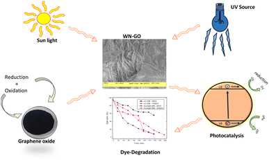 |
| | Fig. 13 Efficient degradation of MB dye and the role of graphene samples in enhancing the photocatalytic activity. | |
5 Conclusions
The objective of this study was to investigate the influence of NaNO3 and CaCl2 on the synthesis of graphene oxide (GO) and reduced graphene oxide (RGO) and their subsequent application in the photocatalytic degradation of methylene blue (MB) dye under both UV and sunlight exposure conditions. We aimed to assess the effectiveness of different synthesis processes and determine the most suitable approach for achieving efficient and environmentally friendly degradation of the dye. The experimental results demonstrated thatthe synthesis of GO without the addition of NaNO3, referred to as WN-GO, did not significantly affect the yield of the final product. Moreover, WN-GO exhibited the elimination of toxic gas evolution during the synthesis process, indicating its environmentally friendly nature. On the other hand, the inclusion of CaCl2 in the synthesis procedure served as a catalyst, effectively enhancing the reduction ability of NaBH4, specifically targeting the removal of oxygen-containing functional groups from the GO structure. Based on their comprehensive analysis, the study concluded that the synthesis methods involving WN-GO and WN-C-RGO yielded the most favourable results. Specifically, WN-GO exhibited efficient degradation of MB dye under both UV and sunlight irradiation as compare to WN-C-RGO. This suggests that WN-GO possessed superior photocatalytic properties, making it highly suitable for organic and eco-friendly degradation of dye contaminants in water. In light of these findings, we proposed that the synthesized WN-GO material holds potential for application in the bioremediation of wastewater treatment. By harnessing its enhanced photocatalytic degradation capabilities, WN-GO could serve as a valuable tool for the removal of dye pollutants from contaminated water sources, thereby contributing to the improvement of environmental sustainability and water quality.
Conflicts of interest
The authors hereby declare that we have no known competing financial interests or personal relationships that could have appeared to influence the work reported in this paper.
Acknowledgements
The authors are grateful to Chitkara University, Punjab for support and institutional facilities. The work was supported by Researchers Supporting Project number (RSPD2023R663), King Saud University, Riyadh, Saudi Arabia.
Notes and references
- S. Patil, N. L. Reddy, G. S. Kamble, D. E. Shinde and K.-Y. Lee, eBooks, IntechOpen, 2022 Search PubMed.
- O. Shenderova, V. Zhirnov and D. W. Brenner, Crit. Rev. Solid State Mater. Sci., 2002, 27, 227–356 CrossRef CAS.
- A. H. C. Neto, F. Guinea, N. M. R. Peres, K. S. Novoselov and A. K. Geim, Rev. Mod. Phys., 2009, 81, 109–162 CrossRef.
- D. Verma, P. C. Gope, A. Shandilya and A. Gupta, Trans. Indian Inst. Met., 2014, 67, 803–816 CrossRef CAS.
- W. Choi, I. Lahiri, R. Seelaboyina and Y. S. Kang, Crit. Rev. Solid State Mater. Sci., 2010, 35, 52–71 CrossRef CAS.
- S. Stankovich, D. A. Dikin, G. H. B. Dommett, K. M. Kohlhaas, E. J. Zimney, E. A. Stach, R. D. Piner, S. T. Nguyen and R. S. Ruoff, Nature, 2006, 442, 282–286 CrossRef CAS PubMed.
- A. B. Kuzmenko, E. van Heumen, F. Carbone and D. van der Marel, Phys. Rev. Lett., 2008, 100, 117401 CrossRef CAS PubMed.
- S. Sheshmani and M. A. Fashapoyeh, Acta Chim. Slov., 2013, 60, 813–825 CAS.
- P. T. Yin, S. Shah, M. Chhowalla and K.-B. Lee, Chem. Rev., 2015, 115, 2483–2531 CrossRef CAS PubMed.
- C. Miao, C. Zheng, O. Liang and Y.-H. Xie, Physics and applications of graphene-experiments, 2011 Search PubMed.
- J. Hass, W. A. de Heer and E. H. Conrad, J. Phys.: Condens.Matter, 2008, 20, 323202 CrossRef.
- N. Li, Z. Chen, W. Ren, F. Li and H.-M. Cheng, Proc. Natl. Acad. Sci. U. S. A., 2012, 109, 17360–17365 CrossRef CAS PubMed.
- N. Zaaba, K. Foo, U. Hashim, S. Tan, W.-W. Liu and C. Voon, Procedia Eng., 2017, 184, 469–477 CrossRef CAS.
- Z. Lin, Y. Liu, Z. Li and C.-P. Wong, Novel preparation of functionalized graphene oxide for large scale, low cost, and self-cleaning coatings of electronic devices, in 2011 IEEE 61st Electronic Components and Technology Conference (ECTC), IEEE, 2011, pp. 358–362 Search PubMed.
- J. Rafiee, M. A. Rafiee, Z.-Z. Yu and N. Koratkar, Adv. Mater., 2010, 22, 2151–2154 CrossRef CAS PubMed.
- K. S. Novoselov, A. Geim, S. Morozov, D. Jiang, Y. Zhang, S. Dubonos and A. Firsov, Science, 2004, 306, 666–669 CrossRef CAS PubMed.
- W. S. Hummers and R. E. Offeman, J. Am. Chem. Soc., 1958, 80, 1339 CrossRef CAS.
- D. C. Marcano, D. V. Kosynkin, J. M. Berlin, A. Sinitskii, Z. Sun, A. Slesarev, L. B. Alemany, W. Lu and J. M. Tour, ACS Nano, 2010, 4, 4806–4814 CrossRef CAS PubMed.
- J. Chen, B. Yao, C. Li and G. Shi, Carbon, 2013, 64, 225–229 CrossRef CAS.
- K. Krishnamoorthy, R. Mohan and S.-J. Kim, Appl. Phys. Lett., 2011, 98, 244101 CrossRef.
- F. Jamal, A. Rafique, S. Moeen, J. Haider, W. Nabgan, A. Haider, M. Imran, G. Nazir, M. Alhassan, M. Ikram and Q. Khan, ACS Appl. Nano Mater., 2023, 6, 7077–7106 CrossRef CAS.
- S. Moeen, M. Ikram, A. Haider, J. Haider, A. Ul-Hamid, W. Nabgan, T. Shujah, M. Naz and I. Shahzadi, ACS Omega, 2022, 7, 46428–46439 CrossRef CAS PubMed.
- M. Ikram, A. Haider, M. Imran, J. Haider, S. Naz, A. Ul-Hamid, A. Shahzadi, S. Moeen, G. Nazir, W. Nabgan and A. Bashir, Surf. Interfaces, 2023, 37, 102710 CrossRef CAS.
- M. Ikram, S. Moeen, A. Haider, A. Ul-Hamid, H. Alhummiany, H. H. Somaily, S. Goumri-Said and M. B. Kanoun, Nano Mater. Sci., 2023 DOI:10.1016/j.nanoms.2023.11.007.
- I. S. Sandhu, M. Chitkara, S. Rana, G. Dhillon, A. Taneja and S. Kumar, Opt. Quantum Electron., 2020, 52, 1–16 CrossRef.
- I. S. Sandhu, M. Chitkara, G. Dhillon, S. Rana and A. Kumar, Opt. Quantum Electron., 2021, 53, 1–14 CrossRef.
- B. Zhu, J. Zhou, L. Ni and G. Diao, Solid State Sci., 2023, 139, 107158 CrossRef CAS.
- S. K. Kuila, R. Sarkar, P. Kumbhakar, C. S. Tiwary and T. K. Kundu, J. Environ. Chem. Eng., 2020, 8, 103942 CrossRef CAS.
- C. A. Zito, T. M. Perfecto and D. P. Volanti, ACS Appl. Nano Mater., 2023, 6, 9041–9049 CrossRef CAS.
- N. Cao and Y. Zhang, J. Nanomater., 2015, 2015, 1–5 Search PubMed.
- H. Shin, K. K. Kim, A. Benayad, S. Yoon, H. K. Park, I. Jung, M. H. Jin, H. Jeong, J. M. Kim, J. Choi and Y. H. Lee, Adv. Funct. Mater., 2009, 19, 1987–1992 CrossRef CAS.
- C. K. Chua and M. Pumera, J. Mater. Chem. A, 2013, 1, 1892–1898 RSC.
- S. Pei and H.-M. Cheng, Carbon, 2012, 50, 3210–3228 CrossRef CAS.
- Z. z. Yang, Q. b. Zheng, H. x. Qiu, J. Li and J. h. Yang, Carbon Mater., 2015, 86, 372 CrossRef.
- M. Periasamy and M. Thirumalaikumar, J. Organomet. Chem., 2001, 609, 137–151 CrossRef.
- J. Li, H. Lin, Z. Yang and J. Li, Carbon, 2011, 49, 3024–3030 CrossRef CAS.
- C. H. Manoratne, S. R. D. Rosa and I. R. M. Kottegoda, Mater. Sci. Res. India, 2017, 14, 19–30 CAS.
- C. K. Chua and M. Pumera, Chem. Soc. Rev., 2014, 43, 291–312 RSC.
- D. R. Chowdhury, C. Singh and A. Paul, RSC Adv., 2014, 4, 15138 RSC.
- P. Khanra, P. Kumar and T. Kuila, Preparation of high performance LaMnO3/graphene composites for hybrid electrode material, in AIP Conference Proceedings, 2019, vol. 2142(1) Search PubMed.
- P. Khanra, M. Kapoor and P. Kumar, Facile synthesis of graphene/manganese carbonate as cathode materials for supercapacitor application, in AIP Conference Proceedings, 2022, vol. 2357(1) Search PubMed.
|
| This journal is © The Royal Society of Chemistry 2024 |
Click here to see how this site uses Cookies. View our privacy policy here. 
 Open Access Article
 This Open Access Article is licensed under a Creative Commons Attribution-Non Commercial 3.0 Unported Licence
 *ab,
Latha Marasamyd,
Sirajul Haq
*ab,
Latha Marasamyd,
Sirajul Haq