
 Open Access Article
 This Open Access Article is licensed under a Creative Commons Attribution-Non Commercial 3.0 Unported Licence
Cu and Zn promoted Al-fumarate metal organic frameworks for electrocatalytic CO2 reduction†
Ung Thi Dieu Thuy *a,
Tran Ngoc Huan*b,
Sandrine Zannac,
Karen Wilsond,
Adam F. Leed,
Ngoc-Diep Leb,
Jim Mensahe,
Venkata D. B. C. Dasireddyd and
Nguyen Quang Liem*a
*a,
Tran Ngoc Huan*b,
Sandrine Zannac,
Karen Wilsond,
Adam F. Leed,
Ngoc-Diep Leb,
Jim Mensahe,
Venkata D. B. C. Dasireddyd and
Nguyen Quang Liem*a
aInstitute of Materials Science, Vietnam Academy of Science and Technology, 18 Hoang Quoc Viet, Cau Giay, Hanoi, Vietnam. E-mail: dieuthuy@ims.vast.vn; liemnq@vast.vn
bLaboratoire de Chimie des Processus Biologiques, Collège de France, Sorbonne Université, 11 Place Marcelin Berthelot, 75231 Paris Cedex 05, France. E-mail: ngoc-huan.tran@college-de-france.fr
cChimie ParisTech, PSL Research University, CNRS, Institut de Recherche de Chimie Paris (IRCP), 11 rue Pierre et Marie Curie, 75005 Paris, France
dSchool of Environment & Science, Centre for Catalysis and Clean Energy, Griffith University, Gold Coast Campus, QLD 4222, Australia
eCentre for Applied Materials and Industrial Chemistry (CAMIC), RMIT University, Australia
First published on 22nd January 2024
Abstract
Metal organic frameworks (MOFs) are attractive materials to generate multifunctional catalysts for the electrocatalytic reduction of CO2 to hydrocarbons. Here we report the synthesis of Cu and Zn modified Al-fumarate (Al-fum) MOFs, in which Zn promotes the selective reduction of CO2 to CO and Cu promotes CO reduction to oxygenates and hydrocarbons in an electrocatalytic cascade. Cu and Zn nanoparticles (NPs) were introduced to the Al-fum MOF by a double solvent method to promote in-pore metal deposition, and the resulting reduced Cu–Zn@Al-fum drop-cast on a hydrophobic gas diffusion electrode for electrochemical study. Cu–Zn@Al-fum is active for CO2 electroreduction, with the Cu and Zn loading influencing the product yields. The highest faradaic efficiency (FE) of 62% is achieved at −1.0 V vs. RHE for the conversion of CO2 into CO, HCOOH, CH4, C2H4 and C2H5OH, with a FE of 28% to CH4, C2H4 and C2H5OH at pH 6.8. Al-fum MOF is a chemically robust matrix to disperse Cu and Zn NPs, improving electrocatalyst lifetime during CO2 reduction by minimizing transition metal aggregation during electrode operation.
1. Introduction
The electrochemical reduction of CO2 into hydrocarbon fuels is a promising strategy to reduce societal reliance on fossil fuels and anthropogenic CO2 emissions, while meeting global energy demands. To achieve this goal, the design and development of suitable functional materials which can effectively catalyse CO2 reduction into fuels using cheap and renewable energy is required.1–3 Homogeneous and heterogeneous catalysts, including transition metal complexes of Pd, Re, Ru, Mn, Fe, Co, Ni and Cu, heterogenized molecular catalysts, nanostructured metals, metal chalcogenides and heteroatom-doped carbons have been explored.4–6 Multi-carbon products can form efficiently over Cu catalysts, being the preferred metal to promote C–C coupling reactions during CO2 electroreduction.1,4 CO2 reduction to multi-carbon products proceeds via a CO intermediate, which undergoes additional multi-electron reduction, hence many studies target multifunctional catalysts in which a second active site selective for the reduction of CO2 to CO, is incorporated alongside Cu. This enables a tandem process in which CO2 reduction selectively produces CO for subsequent reduction and/or coupling over Cu sites to produce (oxygenated) hydrocarbons.5–7 Zn is selective for CO2 electroreduction to CO,8 and in combination with Cu facilitates deeper reduction or coupling products (CH3OH, CH4, C2H4 or C2H5OH).9–11Metal–organic frameworks (MOFs) are attractive scaffolds that are readily functionalised with metal- or metal oxide-based nanoparticles for diverse applications including adsorption, membrane separation and catalysts.12–16 The high porosity, large surface area and chemical flexibility of MOFS renders them well-suited for fabricating multifunctional materials,13,14 with properties are tailored by changing the metal nodes or organic linkers, or introducing metal precursors within the pore network to create highly dispersed metal or metal oxide nanoparticles (NPs) with enhanced catalysis. Stabilization of such dispersed metal and metal oxide NPs may prevent their agglomeration and deactivation. MOFs have found application in electrocatalytic CO2 reduction,13,17–20 with Jiang et al. reporting a Ag2O/layered ZIF-7 catalyst, comprising Ag2O NPs and a ZIF-7 MOF, that affords 81% faradaic efficiency (FE) for CO2 electroreduction to CO to at −1.2 V vs. RHE in 0.25 M K2SO4. This value was much greater than that achieved with either ZIF-7 (25%) or Ag/C (36%) components.21 Hupp et al. embedded Cu NPs within Zr-MOF (NU-1000), obtaining a FE of 28% for CO2 electroreduction reaction at −0.82 V vs. RHE, with formate (HCOO−) as the major product,22 while Beobide et al. reported a HKUST-1(Cu,Ru) heterometallic electrocatalyst formed by partially replacing Cu(II) nodes in the MOF with Ru(III) nodes, resulting in a combined FE of 47% for CO2 conversion to methanol and ethanol. However, the latter electrocatalyst deactivated after 60 min of operation to a stable FE of only ∼10%.23
Metal-doped MOFs are hence promising electrocatalysts for CO2 reduction, with multimetallic catalysts desirable to optimize product selectivity. Al-fumarate MOFs exhibit excellent thermal and chemical stability, alongside their high surface area and porosity,24 but to our knowledge have not been investigated for CO2 electroreduction. Here we explore the utility of Al-fumarate MOFs to: (i) synthesise Cu and Zn doped analogues for the cascade reduction of CO2 to CO and subsequent multicarbon products; and (ii) improve active site dispersion and catalyst lifetime. Multimetallic Al-fumarate MOFs (Cu–Zn@Al-fum MOFs) with different metal loadings and Cu![[thin space (1/6-em)]](https://www.rsc.org/images/entities/char_2009.gif) :Zn ratios were used to fabricate catalytic gas diffusion electrodes. Electroreduction of CO2 was effective at neutral pH, with a FE of 27% to CO, 28% to hydrocarbons (CH4, C2H4, C2H5OH) and 7% to HCOOH at −1.0 V vs. RHE.
:Zn ratios were used to fabricate catalytic gas diffusion electrodes. Electroreduction of CO2 was effective at neutral pH, with a FE of 27% to CO, 28% to hydrocarbons (CH4, C2H4, C2H5OH) and 7% to HCOOH at −1.0 V vs. RHE.
2. Experimental
2.1 Preparation of Al-fum MOF
Al-fum MOF were prepared as follows.24 In a 500 mL three-neck flask, 0.05 mol of Al2(SO4)3·18H2O was dissolved in 150 mL of DI water and heated to 65 °C. A 150 mL mixture containing an aqueous solution of 0.10 mol fumaric acid and 0.21 mol sodium hydroxide was injected into the reaction flask containing the aluminum precursor at 65 °C and stirred vigorously for 1 h. The obtained white suspension was filtered, then washed with DI water and warm ethanol. The washed Al-fum MOF product was dried overnight at 100 °C in air and subsequently at 130 °C in a vacuum oven.2.2 Fabrication of Cu@Al-fum MOF
1 g of Al-fum MOF was dispersed in 50 mL of n-hexane and sonicated for 20 min to obtain a white suspension. Next, a certain volume of aqueous 1.45 mM Cu(NO3)2·3H2O was added gradually under vigorous stirring. After stirring for 8 h, the blue solid was decanted and washed with n-hexane until the blue color of Cu2+ from the washing solution was clear. This precipitated solid was dried under vacuum at 80 °C overnight to obtain Cu2+@Al-fum MOF. Cu2+@Al-fum MOF which was then reduced by dispersing in 50 mL of CH2Cl2 and stirred vigorously for 30 min under N2, prior to dropwise addition of a 25 mL NaBH4 solution (prepared by dissolving 0.47 g of NaBH4 in 25 mL of ethanol). The solution changed from light blue to yellow brown and then black as reduction proceeded. The product was collected by centrifugation and purified by dispersing in ethanol five times. The Cu@Al-fum MOF solid precipitate was dried under vacuum for overnight, and hereafter is termed Cu@Al-fum.2.3 Fabrication of Cu–Zn@Al-fum MOF
A Cu–Zn@Al-fum MOF was prepared similarly to Cu@Al-fum, except that Cu and Zn precursors were simultaneously introduced into the Al-fum MOF suspension. Briefly, a certain volume of aqueous Cu(NO3)2 (1.45 mM) and Zn(NO3)2 (3.5 mM) was mixed and added dropwise to a suspension containing 1 g of Al-fum MOF in 50 mL of anhydrous n-hexane under vigorous stirring. The prepared with 0.6 mL Cu2+ and 1.0 mL Zn2+ sample is termed Cu–Zn@Al-fum. After stirring overnight, the solids were collected, washed by n-hexane and dried under vacuum at 80 °C overnight to obtain Cu2+–Zn2+@Al-fum. The Cu2+–Zn2+@Al-fum was then dispersed in 50 mL of CH2Cl2 and stirred vigorously for 30 min under N2 prior to reduction with fresh NaBH4 solution which was added gradually into the reaction flask. The resulting Cu–Zn@Al-fum was collected, purified and dried akin to Cu@Al-fum MOF.2.4 Fabrication of the electrode for CO2 electroreduction
The working electrode was prepared by drop-casting aqueous suspensions of Cu@Al-fum MOFs or Cu–Zn@Al-fum MOFs onto a hydrophobic gas diffusion electrode (GDE) (dioxide, AvCarb GDS5130), on a hot plate at 80 °C. The solution for deposition was prepared with 1 mg catalyst (metal-impregnated MOFs) in 150 μL ethanol with 5 μl Nafion 5% (Sigma-Aldrich). The final 1 cm2 electrode was dried in air before use.2.5 Characterization
Morphology, structure and chemical composition of Al-fum MOFs were characterized by a transmission electron microscope (TEM, Hitachi H-7100, Japan), field emission scanning electron microscope (SEM, JEOL JSM-7600F, Japan), and powder X-ray diffraction (XRD, Shimadzu XRD-6000, Japan). Thermal stability was determined by thermogravimetric analysis (TGA, Mettler Toledo TGA/SDTA 851, USA) under a dry nitrogen flow of 30 mL min−1, under heating at 5 °C min−1 from 32 to 700 °C. Brunauer–Emmett–Teller (BET) and Barrett–Joyner–Halenda (BJH) methods were applied to determine the specific surface area and pore size, respectively from N2 physisorption isotherms (Quantachrome Nova 4200e porosimeter at 77 K). X-ray photoelectron spectra were acquired (Thermo Scientific K-alpha instrument) using a monochromatic Al Kα (1486.7 eV) source and charge neutralizer to investigate surface properties. Bulk Cu and Zn loadings were determined by inductively coupled plasma-optical emission spectrometry (ICP-OES, PerkinElmer, USA). Electrochemical impedance spectroscopy (EIS, Biologic SP-300) were measured with frequencies ranging from 100 kHz to 0.1 Hz at a potential of −1.0 V vs. RHE in 0.1 M KHCO3, and the amplitude of the applied voltage was 10 mV. Gas chromatography (GC, SRI instruments, MG#5 GC) was used to analyze the gaseous products from CO2 electroreduction and 1H nuclear magnetic resonance (NMR, Bruker Avance III 300 MHz) was used to analyze liquid products; further details are provided in the ESI.†2.6 Evaluation of electrocatalytic CO2 reduction
CO2 electroreduction was performed by a chronopotentiostatic method at different potentials, using an H-type electrochemical cell, which consists of two compartments separated by an anion exchange membrane (Dioxide, X37-50 grade T) containing the working, counter and reference electrodes. In the anodic compartment, Pt wire was the anode for the water oxidation reaction. In the cathodic compartment, CO2 reduction was performed using catalysts deposited on the GDE in 0.1 M KHCO3 solution-saturated CO2 (pH 6.8) with a Ag/AgCl reference electrode. During electrolysis, CO2 was continuously bubbled at a flow rate of 7.5 mL min−1; the headspace was sampled by online GC for quantification of H2, CO, CH4, C2H4, with formate and ethanol quantified by ion chromatography and NMR respectively. Details of FE calculations are presented in the ESI.†3. Results and discussion
3.1 Morphological and structural characterization
Al-fum with a high specific surface area, porosity and excellent water stability was successfully synthesized by precipitating aluminum sulphate with fumaric acid at 65 °C.24 Cu and Cu–Zn NPs analogues were prepared by impregnation of metal salts into the Al-fum MOFs using the double solvent method (Fig. 1). | ||
| Fig. 1 Schematic of Cu@Al-fum and Cu–Zn@Al-fum MOF synthesis. | ||
The composition, texture and structure properties of Al-fum, Cu@Al-fum and Cu–Zn@Al-fum were first determined by ICP and N2 porosimetry and XRD; the Cu mass and molar loading in Cu@Al-fum was similar to the combined [Cu + Zn] loading in Cu–Zn@Al-fum of ∼3 wt% (Table 1). The BET surface area and average pore diameter of Al-fum were ∼1073 m2 g−1 and 1.7 nm respectively, in good agreement with the literature.24–26 Note the average pore diameter is larger than the 0.6 nm of the rhombohedral channels of the MOF framework due to mesoporous intercrystallite voids27 (with a mode pore diameter of ∼8 nm). The pore diameter increases after Cu and Cu/Zn doping, likely due to enlargement of intercrystallite voids. The decrease in surface areas of Cu@Al-fum and Cu–Zn@Al-fum compared to Al-fum is attributed to incorporation of dense Cu and Zn NPs within the low density MOF, and resultant partial micropore blockage. This observation concurs with a previous report of Al-fum and CuO/ZnO/AlFum MOFs wherein surface areas decreased from 910 to 416 m2 g−1.28
| Samples | Elemental loadinga (wt%) | SBETb (m2.g−1) | Pore volumeb (cm3 g−1) | Pore diameterc (nm) | |
|---|---|---|---|---|---|
| Cu | Zn | ||||
| a ICP analysis.b Error in SBET and pore volume ±10%.c Modal value of mesopore diameter in brackets. | |||||
| Al-fum | — | — | 1073 | 1.4 | 1.7 (8.3) |
| Cu@Al-fum | 2.92 | — | 335 | 0.8 | 1.9 (11) |
| Cu–Zn@Al-fum | 0.86 | 2.18 | 560 | 1.2 | 1.9 (19) |
The hydrophilicity of Al-fum MOF after Cu and Zn incorporation was evaluated from water adsorption isotherms (Fig. S1a†). Water adsorption decreased 3.5 times after introducing Cu and Zn into the Al-fum MOF, partly reflecting the lower surface area and pore volume, but also indicative of decreased hydrophilicity.
Fig. 2 shows the XRD patterns of Al-fum, Cu@Al-fum and Cu–Zn@Al-fum, with the former (Fig. 2a) exhibiting diffraction peaks at 2θ of ∼10.6, 15.2, 21.2, 31.8 and 42.8° corresponding to the (011), (020), (022), (033) and (044) planes of monoclinic Al-fum MOF crystals.
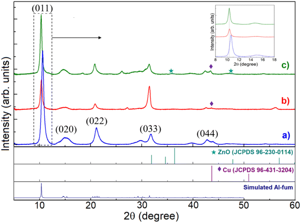 | ||
| Fig. 2 XRD patterns of (a) Al-fum, (b) Cu@Al-fum and (c) Cu–Zn@Al-fum. Inset shows the magnification of the (011) peak. | ||
Cu@Al-fum and Cu–Zn@Al-fum exhibit similar reflections to Al-fum, suggesting that the former retain the crystalline structure of the parent MOF. No reflections associated with copper oxides were observed (Fig. 2b), however a very weak peak at 42° in Cu@Al-fum is characteristic of copper metal. For Cu–Zn@Al-fum, small reflections at 36.4° and 43.7° are indicative of ZnO (Fig. 2c), although no reflections associated with Zn metal were observed (Zn being more easily oxidized than Cu). The low intensities of Cu and ZnO reflections is consistent with their low loading in the doped MOF.28 The (011) reflection of the parent Al-fum MOF slightly shifts to lower angle (by ∼0.3°) following Cu and Cu–Zn modification (Fig. 2 inset), indicating lattice expansion which we ascribe to lattice stress/strain or defects (dislocations or stacking faults) arising from the incorporation of Cu and Zn NPs into the MOF framework.29
SEM and TEM images of Cu–Zn@Al-fum (Fig. 3) and of Cu@Al-fum (Fig. S1b†) reveal aggregates of relatively uniform sheets (average width ∼50–100 nm), similar to the parent Al-fum MOF and consistent with previous reports.24,27 TEM images and EDX elemental maps (Fig. 3, S1b and S2†) evidence <6 nm Cu and Zn NPs uniformly distributed throughout the Al-fum MOF, akin to reports of Cu and Zn NPs dispersed in UiO-66 or Ni NPs in Zr MOFs.30–32
 | ||
Fig. 3 (Top) SEM and TEM images, and (middle, bottom) EDX elemental maps of Cu–Zn@Al-fum. Arrows in the TEM image indicate <6 nm Cu and/or Zn NPs. FTIR spectra of Al-fum, Cu@Al-fum and Cu–Zn@Al-fum (Fig. 4a) confirmed the molecular components of the MOF framework. Bands at ∼1610 cm−1, 1430 cm−1, 1158 cm−1 and 805 cm−1 are attributed to asymmetric and symmetric stretches of the carboxylate group in fumarate (which coordinates to Al3+ nodes).33,34 Bands spanning 720–650 cm−1 arise from C![[double bond, length as m-dash]](https://www.rsc.org/images/entities/char_e001.gif) C and C–H bending modes of the fumarate framework, while the broad band from 3400–3600 cm−1 is due to the O–H stretch of in-pore or intercrystallite water. New bands are visible <650 cm−1 following Cu and Zn doping, attributed to Cu–O stretches in Cu2O (expected ∼615–630 cm−1) and CuO (expected ∼609–590 cm−1 and ∼530–508 cm−1),35 and copper coordinated to carboxylate groups (<450 cm−1)36 in addition to Zn–O stretches (expected <555 cm−1).37 C and C–H bending modes of the fumarate framework, while the broad band from 3400–3600 cm−1 is due to the O–H stretch of in-pore or intercrystallite water. New bands are visible <650 cm−1 following Cu and Zn doping, attributed to Cu–O stretches in Cu2O (expected ∼615–630 cm−1) and CuO (expected ∼609–590 cm−1 and ∼530–508 cm−1),35 and copper coordinated to carboxylate groups (<450 cm−1)36 in addition to Zn–O stretches (expected <555 cm−1).37 | ||
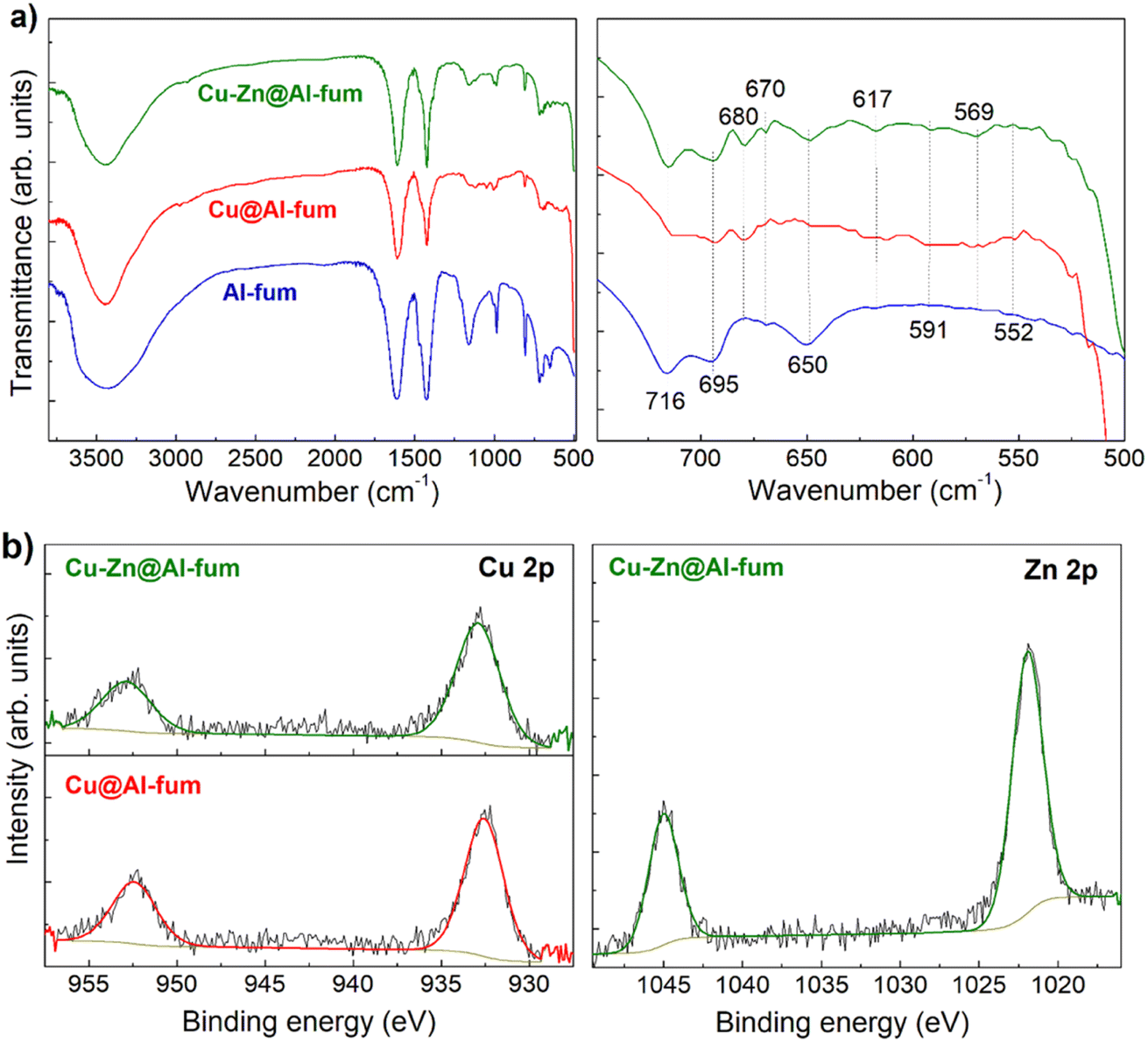 | ||
| Fig. 4 (a) FTIR spectra of Al-fum MOFs, and (b) Cu and Zn 2p XP spectra of Cu@Al-fum and Cu–Zn@Al-fum. | ||
A survey scan by XPS identified the presence of C, O, Al, Cu and Zn in Cu@Al-fum and Cu–Zn@Al-fum (Fig. S3a†). Corresponding high-resolution C 1s XPS spectra (not shown) reveal three peaks with binding energies of 284.6, 286.2 and 288.4–288.8 eV, attributed to C–C/C–H/CC, C–O and CO groups, respectively of the fumarate framework.38–40 The Al-fum exhibits Al 2p spin–orbit split peaks at ∼74.4 and 75.5 eV (Fig. S3b†), assigned to AlO(OH) species within the MOF framework,41 and two O 1s peaks at ∼531.9 eV and 533.2 eV (Fig. S3c†) characteristic of metal and H-bonded oxygen respectively.42 Small shifts in the principal Al 2p and O 1s peaks to lower binding energy following metal doping (Fig. S3b and c†) may reflect tensile or compressive strains in the Al-fum MOF framework and a concomitant change in the Al3+ charge density.
Unreduced Cu@Al-fum and CuZn@Al-fum samples exhibit Cu 2p3/2 and 2p1/2 spin–orbit split peaks at 933.2 and 953.0 eV respectively, which (in conjunction with the absence of a copper satellite) indicates the presence of Cu+ species (Fig. S4†). Following NaBH4 reduction, the Cu 2p binding energies decreased slightly to 932.6 and 952.4 eV for Cu@Al-fum and 932.8 and 952.7 eV for Cu–Zn@Al-fum (Fig. 4b and S4†) consistent with the formation of some metallic Cu.43 In both cases, the Auger parameter calculated using the Cu LMM peak ∼918.2 eV kinetic energy (Fig. S5†) was 1851.4 eV, consistent with Cu metal.44 A similar binding energy red-shift was observed for the Zn 2p spectra following NaBH4 reduction, from ∼1022.3 for Zn2+ species in Cu2+Zn2+@Al-fum to 1021.9 eV for Cu–Zn@Al-fum (Fig. 4b and S4†). This shift may reflect chemical reduction of Zn2+ to Zn or electronic perturbation due to alloying with copper.32 It is challenging to distinguish Zn and ZnO from XPS due to their similar binding energy values,45 however the formation of Zn NPs in MOF pore networks is known.46–48
The porosity of the Al-fum, Cu@Al-fum and Cu–Zn@Al-fum MOFs was analyzed using nitrogen porosimetry (Fig. S6a†), which reveals the parent and metal-impregnated MOF samples exhibit typical I isotherm behavior, indicating the existence of both microporous and mesoporous structures. The BJH pore size distribution (Fig. S6b†) reveals all samples show a broad range of mesopores with a mode of ∼8 nm for Al-fum, increasing to 11 and 19 nm for Cu@Al-fum MOF and Cu–Zn@Al-fum respectively, which are attributed to intercrystallite voids, and is in good agreement with observations from SEM in Fig. 3 and S1b.†
Thermal analysis of Al-fum reveals mass losses at ∼50 °C and 475 °C (Fig. S7†) corresponding to the removal of physisorbed water and adsorbed/coordinated solvent (∼30 wt%) and subsequent decomposition of the fumarate organic linker (∼35 wt%). The residual ∼35 wt% is associated with reactively-formed alumina. Al-fum is thus thermally stable to 475 °C, in good agreement with previous reports.24,26,28 Impregnation with Cu and Zn NPs lowers the thermal stability, with the frameworks of Cu@Al-fum and Cu–Zn@Al-fum decomposing at 435 °C and 447 °C respectively, and new lower temperature mass losses emerging at 320 °C and 340 °C, respectively. We speculate that the presence of metal NPs promotes defect formation (missing Al3+ nodes or fumarate linkers) and/or lattice strain, destabilizing the parent framework, consistent with literature reports.28 Nevertheless, Cu@Al-fum and Cu–Zn@Al-fum are stable to 320 °C, higher than many MOFs.49,50
3.2 Electrocatalytic reduction of CO2
The electrocatalytic reduction of CO2 over Al-fum derived catalysts was evaluated using a bespoke H-cell (Fig. S8a†), with two compartments separated by an anion exchange membrane (AEM). To maximize catalytic performance, CO2 was injected through a glass frit at the base of cathodic compartment to produce a stream of small bubbles transported to the catalyst deposited on the hydrophobic GDE. All electrocatalysts achieved steady-state operation after 30 min time-on-stream with an example shown for Cu–Zn@Al-fum under the operating potentials studied (Fig. S8b†).The catalytic performance of Cu–Zn@Al-fum was evaluated by linear sweep voltammetry (LSV) in the presence and absence of CO2 (Fig. 5). Under an Ar atmosphere, liquid and gas analysis confirmed that the faradaic current density (j) was entirely due to the hydrogen evolution reaction (HER), whereas in the presence of a CO2-saturated solution j reflects competition between proton and CO2 reduction. Hydrogen production was greatly suppressed under a CO2 atmosphere, with the chemical selectivity (on a molar basis) to reduced carbon products reaching 50% for Cu–Zn@Al-fum at −1.2 V vs. RHE (Table S1†). A similar switchover from proton reduction under Ar to CO2 reduction in a CO2 saturated aqueous solution is reported in the literature.51–53 Note that the molar selectivity to reduced carbon products is always lower than the FE, as the latter accounts for the greater number of electrons required to form e.g. C2H4 (12 e−) than H2 (2 e−). Although the electrolyte pH decreased from 8.3 under Ar to 6.8 for a CO2 saturated solution (which could result in a positive shift in potential for H2 generation),54 there was no evidence for a systematic increase in H2 production at more positive potentials (Fig. 5 and S9†). Literature reports suggest that CO2 reduction is more pronounced at lower pH,51 which could result in the higher current density of Cu–Zn@Al-fum/GDE under CO2 saturation (Fig. 5a). Considering that LSV curves are a convolution of catalyst activity and selectivity, differences between them can only be interpreted following analysis of evolved CO2 reduction products, with formation of CO, HCOOH, CH4, C2H4 and C2H5OH confirmed by GC and NMR (Table S1†). Analogous studies for Cu@Al-fum (Fig. 5c) confirmed the production of gaseous CO, CH4, C2H4 and H2 and liquid formate and ethanol (Table S1†). In contrast, Al-fum only produced H2, CO and formate (Fig. S9†).
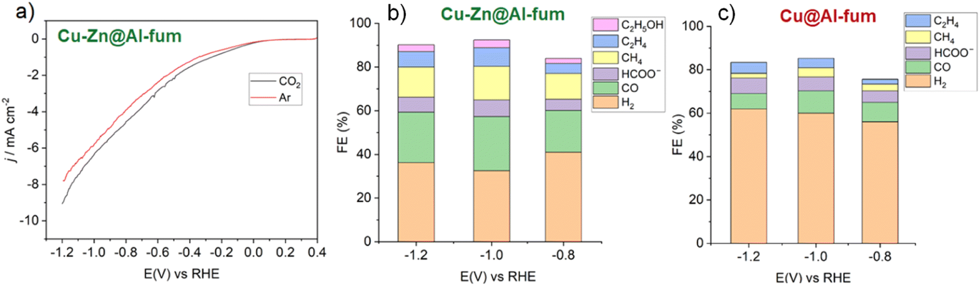 | ||
| Fig. 5 (a) LSV of Cu–Zn@Al-fum/GDE in 0.1 M KHCO3 aqueous solution saturated with CO2 or Ar, and FE for reduction products at different cathodic potentials for (b) Cu@Al-fum, and (c) Cu–Zn@Al-fum. CO2 was continuously bubbled at 7.5 mL min−1 during electrolysis. | ||
Cu–Zn@Al-fum achieved a higher yield of CO2 reduction products than Cu@Al-fum at all applied potentials, reaching an overall FE of 62% for CO2 reduction products (and 32% FE for H2) at −1.0 V vs. RHE. The total FE of Cu–Zn@Al-fum to CH4, C2H4 and C2H5OH (8, 12 and 12 electron reductions, respectively) products alone is ∼34% (Fig. 5b). These efficiencies (selectivities) for CO2 reduction over Cu–Zn@Al-fum at neutral pH compare favorably to literature MOF electrocatalysts (Table 2) prepared by more complex colloidal, atomic layer deposition (ALD) or solvothermal syntheses, which predominantly yield CO.55 Competition between CO2 reduction and H2 evolution will always be challenging, but tuning the solution pH could afford higher yields of multicarbon products. For Cu@Al-fum, H2 production dominated, with a FE >50% at cathodic potentials (Fig. 5c and Table S1†), indicating Cu was relatively poor at activating CO2 under neutral conditions, whereas Cu–Zn@Al-fum exhibited the highest CO yield (Table S1†) consistent with the reported selectivity to this product over Zn electrocatalysts.12 High rates of CO production over Zn are expected to promote deeper reduction and C–C coupling reactions over proximate Cu sites.11–13
| Type of MOF | j (mA cm−2) | Synthesis | Electrolyte | Maximum FE | Ref. |
|---|---|---|---|---|---|
| Ag@Al-PMOF | ∼6 | ALD, solvothermal | 0.1 M KHCO3 | CO 56% at −1.1 V vs. RHE | 55 |
| Cu NPs embedded NU-1000 (ZIF MOF) | 1.8 | Solvothermal | 0.1 M NaClO4 | Formate 30% and CO 5% at −0.82 V vs. RHE | 21 |
| HKUST-1 + Cu NPs | 20 | Solvothermal | 0.5 M NaHCO3 | C2H4 12% and CH4 19% at −2 V vs. SCE | 57 |
| HKUST-1 + CNT | 8 | Precipitation | 0.5 M KHCO3 | CH4 25%, CO 5% and C2H4 ∼ 1% at −1.06 V vs. RHE | 58 |
| HKUST-1(Cu,Ru) | 20 | Solvent-free synthesis | 0.5 M KHCO3 | CH3OH 1% and C2H5OH 10% at −1.84 V vs. Ag/Ag+ | 23 |
| Cu2O-QDs@CuHHTP MOF | 10.8 | Solvothermal | 0.1 M KCl/0.1 M KHCO3 | CH4 73% at −1.4 V vs. RHE | 19 |
| GO@Cu(BTC) | — | Hydrothermal | 0.1 M KHCO3 | HCOOH 21% at −0.1 V vs. SCE | 50 |
| MIL-53(Al) | 1.2 | Hydrothermal | 0.5 M K2CO3 | HCOOH 19%, CO 21% at −1.1 V vs. RHE | 59 |
| CuZnDTA MOA | 10 | Ultrasonic | 0.5 M KHCO3 | C2H5OH 7%, CH3OH 3% at −1.25 V vs. Ag/Ag+ | 60 |
| Cu@Al-fum MOF | ∼7 | Solvothermal, double solvent | 0.1 M KHCO3 | CO 11%, CH4 6%, C2H4 6% and formate 8% at −1.0 V vs. RHE | This work |
| Cu–Zn@Al-fum MOF | ∼5 | Solvothermal, double solvent | 0.1 M KHCO3 | CO 27%, CH4 16%, C2H4 9%, C2H5OH 3% and formate 7% at −1.0 V vs. RHE | This work |
Further insight into the conductivity of the Al-fum MOF derived catalysts was obtained from electrochemical impedance spectroscopy (EIS) over the frequency range 100 kHz to 0.1 Hz, at a potential of −1.0 V vs. RHE in 0.1 M KHCO3 with 10 mV amplitude for the applied voltage. Resulting Nyquist plots for Al-fum, Cu@Al-fum, and Cu–Zn@Al-fum (Fig. S10†) were fitted to a simplified Randles circuit to extract the charge transfer resistance (Rct, Table S2†).56 The first intercept on the x-axis relates to contact resistance (Rs), and includes the electrode, interfacial contact resistance between the current collector and the electroactive material, and the electrolytic solution resistance. Although Rs values were similar for all catalysts, Rct decreased significantly after Cu and Zn doping, indicating an increased electrical conductivity.
Durability of the Cu–Zn@Al-fum electrocatalyst was also assessed for CO2 electroreduction (Fig. 6): the time-dependent current density increased by ∼10–15% after 4 h time-on-stream, while FE for gaseous CO2 reduction products remained stable.
 | ||
| Fig. 6 Time-dependent CO2 electroreduction over Cu–Zn@Al-fum. | ||
4. Conclusions
Al-fum, Cu@Al-fum and Cu–Zn@Al-fum MOFs were synthesized and deposited on a hydrophobic gas diffusion electrode as electrocatalysts for CO2 reduction in neutral aqueous solutions. Cu and Zn were incorporated into the parent Al-fum MOF by facile co-impregnation of Cu2 and Zn2+ salts which were subsequently reduced to corresponding metal nanoparticles by NaBH4. Co-doping (Cu–Zn@Al-fum) significantly improved CO2 electroreduction compared to a singly doped Cu catalyst (Cu@Al-fum) and the Al-fum (which only catalysed proton reduction). Cu–Zn@Al-fum achieved a FE of 62% for CO2 reduction to CO (27%), and desirable CH4, C2H4 and C2H5OH (28%), and HCOO− (7%) products. This excellent selectivity under neutral pH is attributed to its lower hydrophilicity (suppressing proton reduction) and the proximity of Zn and Cu electrocatalyst sites which promote the cascade reduction of CO2 to CO and formic acid (over Zn) and subsequent reduction of CO to CH4 and multicarbon products (over Cu). The parent Al-fum MOF offers high thermal and chemical stability, and appears an excellent matrix to disperse and stabilize metal NPs during electrochemical operation. This approach should be amenable to diverse Earth abundant metal dopants for CO2 electroreduction to valuable fuels and chemicals.Author contributions
Ung Thi Dieu Thuy: conceptualization, synthesis, analysis, investigation, project administration, writing – review & editing; Tran Ngoc Huan: measure, analysis, writing – review & editing; Sandrine Zanna and Ngoc-Diep Le: measure, analysis; Jim Mensah: characterization and analysis; Venkata D. B. C. Dasireddy: characterization and analysis; Karen Wilson: writing – review & editing; Adam F. Lee: writing – review & editing; Nguyen Quang Liem: conceptualization, writing – review & editing.Conflicts of interest
There are no conflicts of interest to declare.Acknowledgements
This study was funded by the Vietnam Academy of Science and Technology (code NVCC04.09/22-23). We acknowledge Dr Jampaiah Deshetti for assistance with training on analytical equipment. KW and AFL acknowledge funding from the Australian Research Council Center of Excellence – green electrochemical transformation of CO2 (GETCO2) – (CE230100017).References
- S. Nitopi, E. Bertheussen, S. B. Scott, X. Liu, A. K. Engstfeld, S. Horch, B. Seger, I. E. L. Stephens, K. Chan, C. Hahn, J. K. Nørskov, T. F. Jaramillo and I. Chorkendorff, Chem. Rev., 2019, 119, 7610–7672 CrossRef CAS PubMed.
- P. De Luna, C. Hahn, D. Higgins, S. A. Jaffer, T. F. Jaramillo and E. H. Sargent, Science, 2019, 364, eaav3506 CrossRef CAS PubMed.
- M. Serafini, F. Mariani, A. Fasolini, E. T. Brandi, E. Scavetta, F. Basile and D. Tonelli, Adv. Funct. Mater., 2023, 33, 2300345 CrossRef CAS.
- H. P. Duong, N.-H. Tran, G. Rousse, S. Zanna, M. W. Schreiber and M. Fontecave, ACS Catal., 2022, 12, 10285–10293 CrossRef CAS.
- X. Lv, Z. Liu, C. Yang, Y. Ji and G. Zheng, Acc. Mater. Res., 2023, 4, 264–274 CrossRef CAS.
- H. Tang, Y. Liu, Y. Zhou, Y. Qian and B.-L. Lin, ACS Appl. Energy Mater., 2022, 5, 14045–14052 CrossRef CAS.
- C. Wang, C. Wang, Z. Xiong, J. Wang, W. Zhang, H. Shi, D. Wang, Y. Gu, Z. Bai, Y. Gao and X. Yan, Mater. Adv., 2022, 3, 4964–4972 RSC.
- H. S. Jeon, J. Timoshenko, F. Scholten, I. Sinev, A. Herzog, F. T. Haase and B. Roldan Cuenya, J. Am. Chem. Soc., 2019, 141, 19879–19887 CrossRef CAS PubMed.
- I. M. Badawy, A. M. Ismail, G. E. Khedr, M. M. Taha and N. K. Allam, Sci. Rep., 2022, 12, 13456 CrossRef CAS PubMed.
- L. Wan, X. Zhang, J. Cheng, R. Chen, L. Wu, J. Shi and J. Luo, ACS Catal., 2022, 12, 2741–2748 CrossRef CAS.
- Y. Baek, H. Song, D. Hong, S. Wang, S. Lee, Y.-C. Joo, G.-D. Lee and J. Oh, J. Mater. Chem. A, 2022, 10, 9393–9401 RSC.
- B. Rungtaweevoranit, J. Baek, J. R. Araujo, B. S. Archanjo, K. M. Choi, O. M. Yaghi and G. A. Somorjai, Nano Lett., 2016, 16, 7645–7649 CrossRef CAS PubMed.
- T. Stolar, A. Prašnikar, V. Martinez, B. Karadeniz, A. Bjelić, G. Mali, T. Friščić, B. Likozar and K. Užarević, ACS Appl. Mater. Interfaces, 2021, 13, 3070–3077 CrossRef CAS PubMed.
- N. Kornienko, Y. Zhao, C. S. Kley, C. Zhu, D. Kim, S. Lin, C. J. Chang, O. M. Yaghi and P. Yang, J. Am. Chem. Soc., 2015, 137, 14129–14135 CrossRef CAS PubMed.
- B. An, J. Zhang, K. Cheng, P. Ji, C. Wang and W. Lin, J. Am. Chem. Soc., 2017, 139, 3834–3840 CrossRef CAS PubMed.
- D. Yao, C. Tang, A. Vasileff, X. Zhi, Y. Jiao and S.-Z. Qiao, Angew. Chem., Int. Ed., 2021, 60, 18178–18184, DOI:10.1002/anie.202104747.
- Y. Song, Y. Wang, J. Shao, K. Ye, Q. Wang and G. Wang, ACS Appl. Mater. Interfaces, 2022, 14, 20368–20374 CrossRef CAS PubMed.
- G. Liu, Q. T. Trinh, H. Wang, S. Wu, J. M. Arce-Ramos, M. B. Sullivan, M. Kraft, J. W. Ager, J. Zhang and R. Xu, Small, 2023, 2301379 CrossRef CAS PubMed.
- J.-D. Yi, R. Xie, Z.-L. Xie, G.-L. Chai, T.-F. Liu, R.-P. Chen, Y.-B. Huang and R. Cao, Angew. Chem., Int. Ed., 2020, 59, 23641–23648 CrossRef CAS PubMed.
- T. Yan, P. Wang and W.-Y. Sun, Small, 2023, 19, 2206070 CrossRef CAS PubMed.
- X. Jiang, H. Wu, S. Chang, R. Si, S. Miao, W. Huang, Y. Li, G. Wang and X. Bao, J. Mater. Chem. A, 2017, 5, 19371–19377 RSC.
- C.-W. Kung, C. O. Audu, A. W. Peters, H. Noh, O. K. Farha and J. T. Hupp, ACS Energy Lett., 2017, 2, 2394–2401 CrossRef CAS.
- M. Perfecto-Irigaray, J. Albo, G. Beobide, O. Castillo, A. Irabien and S. Pérez-Yáñez, RSC Adv., 2018, 8, 21092–21099 RSC.
- N. T. Loan, N. Thi Hiep, T. Thi Thu Huong, U. Thi Dieu Thuy, T. Thi Thuong Huyen, D. Le Hoang Tan and N. Q. Liem, Adv. Nat. Sci.: Nanosci. Nanotechnol., 2022, 13, 045012 Search PubMed.
- S. karmakar, J. Dechnik, C. Janiak and S. De, J. Hazard. Mater., 2016, 303, 10–20 CrossRef CAS PubMed.
- X. Qian, B. Yadian, R. Wu, Y. Long, K. Zhou, B. Zhu and Y. Huang, Int. J. Hydrogen Energy, 2013, 38, 16710–16715 CrossRef CAS.
- N. Tannert, C. Jansen, S. Nießing and C. Janiak, Dalton Trans., 2019, 48, 2967–2976 RSC.
- Z. G. Duma, X. Dyosiba, J. Moma, H. W. Langmi, B. Louis, K. Parkhomenko and N. M. Musyoka, Catalysts, 2022, 12, 1104 CrossRef CAS.
- R. Su, D. Neffati, Y. Zhang, J. Cho, J. Li, H. Wang, Y. Kulkarni and X. Zhang, Mater. Sci. Eng., A, 2021, 803, 140696 CrossRef CAS.
- Y. Zhu, J. Zheng, J. Ye, Y. Cui, K. Koh, L. Kovarik, D. M. Camaioni, J. L. Fulton, D. G. Truhlar, M. Neurock, C. J. Cramer, O. Y. Gutiérrez and J. A. Lercher, Nat. Commun., 2020, 11, 5849 CrossRef CAS PubMed.
- Z.-W. Zhao, X. Zhou, Y.-N. Liu, C.-C. Shen, C.-Z. Yuan, Y.-F. Jiang, S.-J. Zhao, L.-B. Ma, T.-Y. Cheang and A.-W. Xu, Catal. Sci. Technol., 2018, 8, 3160–3165 RSC.
- Y. Yang, Y. Xu, H. Ding, D. Yang, E. Cheng, Y. Hao, H. Wang, Y. Hong, Y. Su, Y. Wang, L. Peng and J. Li, Catal. Sci. Technol., 2021, 11, 4367–4375 RSC.
- S. Mohamadian-Kalhor, L. Edjlali, H. Basharnavaz and M. Es'haghi, J. Mater. Eng. Perform., 2021, 30, 720–726 CrossRef CAS.
- D. Cheng, L. Zhao, N. Li, S. J. D. Smith, D. Wu, J. Zhang, D. Ng, C. Wu, M. R. Martinez, M. P. Batten and Z. Xie, J. Membr. Sci., 2019, 588, 117204 CrossRef CAS.
- L. Zheng and X. Liu, Mater. Lett., 2007, 61, 2222–2226 CrossRef CAS.
- R. Nivetha, A. Sajeev, A. Mary Paul, K. Gothandapani, S. Gnanasekar, P. Bhardwaj, G. Jacob, R. Sellappan, V. Raghavan, K. Chandar N, S. Pitchaimuthu, S. K. Jeong and A. Nirmala Grace, Mater. Res. Express, 2020, 7, 114001 CrossRef CAS.
- A. Ebrahiminezhad, F. Moeeni, S.-M. Taghizadeh, M. Seifan, C. Bautista, D. Novin, Y. Ghasemi and A. Berenjian, Foods, 2019, 8, 88, DOI:10.3390/foods8030088.
- S. Motozuka, M. Tagaya, K. Hayashi, T. Kameyama, H. Oguri and Z. Xu, J. Compos. Mater., 2017, 51, 3577–3584 CrossRef CAS.
- R. Maiti, A. Midya, C. Narayana and S. K. Ray, Nanotechnology, 2014, 25, 495704 CrossRef CAS PubMed.
- T. N. Huan, E. S. Andreiadis, J. Heidkamp, P. Simon, E. Derat, S. Cobo, G. Royal, A. Bergmann, P. Strasser, H. Dau, V. Artero and M. Fontecave, J. Mater. Chem. A, 2015, 3, 3901–3907 RSC.
- F. Zhang, X. Zou, F. Sun, H. Ren, Y. Jiang and G. Zhu, CrystEngComm, 2012, 14, 5487–5492 RSC.
- I. Platzman, R. Brener, H. Haick and R. Tannenbaum, J. Phys. Chem. C, 2008, 112, 1101–1108 CrossRef CAS.
- A. Radi, D. Pradhan, Y. Sohn and K. T. Leung, ACS Nano, 2010, 4, 1553–1560 CrossRef CAS PubMed.
- X. Wang, L. Qu, J. Zhang, X. Peng and M. Xiao, Nano Lett., 2003, 3, 1103–1106 CrossRef CAS.
- W. Luo, J. Zhang, M. Li and A. Züttel, ACS Catal., 2019, 9, 3783–3791 CrossRef CAS.
- Q. Huang, F. Kang, H. Liu, Q. Li and X. Xiao, J. Mater. Chem. A, 2013, 1, 2418–2425 RSC.
- S. Ho-Kimura, S. J. Moniz, J. Tang and I. P. Parkin, ACS Sustain. Chem. Eng., 2015, 3, 710–717 CrossRef CAS.
- Z. Zhang and P. Wang, J. Mater. Chem., 2012, 22, 2456–2464 RSC.
- C. Healy, K. M. Patil, B. H. Wilson, L. Hermanspahn, N. C. Harvey-Reid, B. I. Howard, C. Kleinjan, J. Kolien, F. Payet, S. G. Telfer, P. E. Kruger and T. D. Bennett, Coord. Chem. Rev., 2020, 419, 213388 CrossRef CAS.
- S. M. Hwang, S. Y. Choi, M. H. Youn, W. Lee, K. T. Park, K. Gothandapani, A. N. Grace and S. K. Jeong, ACS Omega, 2020, 5, 23919–23930 CrossRef CAS PubMed.
- A. R. Paris and A. B. Bocarsly, ACS Catal., 2017, 7, 6815–6820 CrossRef CAS.
- Z. Weng, J. Jiang, Y. Wu, Z. Wu, X. Guo, K. L. Materna, W. Liu, V. S. Batista, G. W. Brudvig and H. Wang, J. Am. Chem. Soc., 2016, 138, 8076–8079 CrossRef CAS PubMed.
- T. N. Huan, P. Prakash, P. Simon, G. Rousse, X. Xu, V. Artero, E. Gravel, E. Doris and M. Fontecave, ChemSusChem, 2016, 9, 2317–2320 CrossRef CAS PubMed.
- N. Sreekantha and K. L. Phani, Chem. Commun., 2014, 50, 11143–11146 RSC.
- Y. T. Guntern, J. R. Pankhurst, J. Vavra, M. Mensi, V. Mantella, P. Schouwink and R. Buonsanti, Angew. Chem., Int. Ed., 2019, 58, 12632–12639 CrossRef CAS PubMed.
- A. R. C. Bredar, A. L. Chown, A. R. Burton and B. H. Farnum, ACS Appl. Energy Mater., 2020, 3, 66–98 CrossRef CAS.
- Y.-L. Qiu, H.-X. Zhong, T.-T. Zhang, W.-B. Xu, P.-P. Su, X.-F. Li and H.-M. Zhang, ACS Appl. Mater. Interfaces, 2018, 10, 2480–2489 CrossRef CAS PubMed.
- Z. Weng, Y. Wu, M. Wang, J. Jiang, K. Yang, S. Huo, X.-F. Wang, Q. Ma, G. W. Brudvig, V. S. Batista, Y. Liang, Z. Feng and H. Wang, Nat. Commun., 2018, 9, 415 CrossRef PubMed.
- M. Lee, A. De Riccardis, R. V. Kazantsev, J. K. Cooper, A. K. Buckley, P. W. W. Burroughs, D. M. Larson, G. Mele and F. M. Toma, ACS Appl. Energy Mater., 2020, 3, 1286–1291 CrossRef CAS.
- J. Albo, D. Vallejo, G. Beobide, O. Castillo, P. Castaño and A. Irabien, ChemSusChem, 2016, 10, 1100–1109 CrossRef PubMed.
Footnote |
| † Electronic supplementary information (ESI) available. See DOI: https://doi.org/10.1039/d3ra07639c |
| This journal is © The Royal Society of Chemistry 2024 |