
 Open Access Article
 This Open Access Article is licensed under a Creative Commons Attribution-Non Commercial 3.0 Unported Licence
Electrical transport properties of [(1 − x)succinonitrile:xpoly(ethylene oxide)]–LiCF3SO3–Co[tris-(2,2′-bipyridine)]3(TFSI)2–Co[tris-(2,2′-bipyridine)]3(TFSI)3 solid redox mediators†
Ravindra Kumar Gupta *a,
Hamid Shaikhb,
Ahamad Imrana,
Idriss Bedjac,
Abrar Fahad Ajajd,
Abdullah Saleh Aldwayyande,
Aslam Khana and
Rashid Ayubf
*a,
Hamid Shaikhb,
Ahamad Imrana,
Idriss Bedjac,
Abrar Fahad Ajajd,
Abdullah Saleh Aldwayyande,
Aslam Khana and
Rashid Ayubf
aKing Abdullah Institute for Nanotechnology, King Saud University, Riyadh 11451, Saudi Arabia. E-mail: rgupta@ksu.edu.sa; aimran@ksu.edu.sa; aslamkhan@ksu.edu.sa
bSABIC Polymer Research Centre, College of Engineering, King Saud University, Riyadh 11421, Saudi Arabia. E-mail: ham-shaikh@ksu.edu.sa
cCornea Research Chair, Department of Optometry, College of Applied Medical Sciences, King Saud University, Riyadh 11433, Saudi Arabia. E-mail: bedja@ksu.edu.sa
dDepartment of Physics and Astronomy, College of Science, King Saud University, Riyadh 11451, Saudi Arabia. E-mail: dwayyan@ksu.edu.sa
eK.A. CARE Energy Research and Innovation Centre, King Saud University, Riyadh, Saudi Arabia
fDepartment of Science, Technology and Innovation Unit, King Saud University, Riyadh 11451, Saudi Arabia. E-mail: rayub@ksu.edu.sa
First published on 2nd January 2024
Abstract
A solid redox mediator (solid electrolyte) with an electrical conductivity (σ25°C) greater than 10−4 S cm−1 is an essential requirement for a dye-sensitized solar cell in the harsh weather of Gulf countries. This paper reports the electrical properties of solid redox mediators prepared using highly dissociable ionic salts: Co[tris-(2,2′-bipyridine)]3(TFSI)2, Co[tris-(2,2′-bipyridine)]3(TFSI)3, and LiCF3SO3 as a source of Co2+, Co3+, and Li+ ions, respectively, in a solid matrix: [(1 − x)succinonitrile:xpoly(ethylene oxide)], where x = 0, 0.5, and 1 in weight fraction. In the presence of large size of cations (Co2+ and Co3+) and large-sized and weakly-coordinated anions (TFSI− and CF3SO3−), only the succinonitrile–poly(ethylene oxide) blend (x = 0.5) resulted in highly conductive amorphous regions with σ25°C of 4.7 × 10⁻⁴ S cm−1 for EO/Li+ = 108.4 and 3.1 × 10⁻⁴ S cm−1 for EO/Li+ = 216.8. These values are slightly lower than 1.5 × 10⁻³ S cm−1 for x = 0 and higher than 6.3 × 10⁻⁷ S cm−1 for x = 1. Only blend-based electrolytes exhibited a downward curve in the log![[thin space (1/6-em)]](https://www.rsc.org/images/entities/char_2009.gif) σ–T−1 plot, a low value of pseudo-activation energy (0.06 eV), a high degree of transparency, and high thermal stability, making it useful for device applications.
σ–T−1 plot, a low value of pseudo-activation energy (0.06 eV), a high degree of transparency, and high thermal stability, making it useful for device applications.
Introduction
The dye-sensitized solar cell (DSSC) is a third-generation solar cell. The DSSC was presented by O'Regan and Gratzel in 1991 using components such as mesoporous and nanostructured n-type semiconducting transparent oxide, TiO2 layer on a fluorine-doped tin oxide (FTO) glass as a working electrode (WE), ruthenium-based dye for light absorption and electron injection into TiO2, I−/I3− redox couple-based liquid redox mediator, and platinized FTO glass as a counter electrode (CE).1 The liquid redox mediator consisted of tetrapropyl ammonium iodide, KI, and iodine in a mixture of ethylene carbonate and acetonitrile (ACN) to regenerate the dye at the dye–TiO2–electrolyte interface, inhibit unwanted back-electron transfer, and regenerate iodide at the CE–electrolyte interface. To date, the highest power conversion efficiency (η), ∼11.9% at 100 mW cm−2, has been achieved for a liquid electrolyte: dimethylpropylimidazolium iodide, I2, LiI, and 4-tert-butylpyridine in acetonitrile with a ruthenium-based dye, and it was commercialized by Sharp.2,3The I−/I3− redox mediator is unsuitable for long-term utility. The iodine shows sublimation, corrosiveness, dissolution of several interconnects and sealants, and visible light absorption, though, partially at ≈430 nm.4–20 To avoid these drawbacks, researchers are looking for fast ion-conducting electrolytes with alternative redox couples.4–20 The metal complex-based liquid/gel redox mediators offered promising cell efficiency at one sun with various dyes. For example, Cu+/Cu2+ redox mediators exhibited η as high as 12.5% for HY64 dye and 13.1% for Y123 + XY1 dyes.18,19 A Co2+/Co3+ redox mediator had η of 13.6% with ZL003 dye.21 The utilization of ionic liquids with ACN led to η of 14.3% with ADEKA-1 + LEG4 dyes.22 The jellification in an inorganic23,24 and organic25,26 frameworks led to promising efficiency at the partial sun value.
Unfortunately, these redox mediators are in either a liquid or a gel state. The liquid nature of the electrolyte in the DSSCs is known to create internal pressure at the high operational temperature (50–80 °C) of Gulf regions, thereby breaking up the device and causing solvent leakage. Though this problem is solvable by hermetic sealing, the DSSC fabrication becomes non-scale-up.6,8,12 This shows a requirement to replace a liquid or gel redox mediator with a solid one. The solid nature of the mediators makes the device compact, safe, and lightweight. Therefore, we started to develop solid redox mediators as a substitute for the commercially available silicon-based solar cells. Silicon-based solar cells are known to exhibit a lower η in high-temperature and desert regions.3
Recently, we reported the first solid Co2+/Co3+ redox mediators with [(1 − x)succinonitrile:xpoly(ethylene oxide)] as a solid matrix, LiTFSI as a source of Li+ ions, and Co[tris-(2,2′-bipyridine)]3(TFSI)2/Co[tris-(2,2′-bipyridine)]3(TFSI)3 as a source of Co2+/Co3+ ions.27 These were based on the optimized ACN-based liquid redox mediator.11 In these mediators, tris-(2,2′-bipyridine) abbreviated as bpy, is a ligand binding to the cobalt ion. The anion, TFSI− standing for bis(trifluoromethyl)sulfonylimide, or (CF3SO2)2N−, has lower values of lattice energy, donor number, and ionic mobility; higher values of molecular weight and dissociation constant; and large ionic size (0.79 nm).28,29 We replaced ACN with either succinonitrile (abbreviated as SN; x = 0 in weight fraction) or poly(ethylene oxide) (abbreviated as PEO; x = 1), or (SN–PEO) blend (x = 0.5). A plastic crystal succinonitrile is an excellent matrix/solid solvent because of its low molecular weight, low melting temperature (Tm), high dielectric constant (ε), ion transport through the nitrile group, and waxy nature.30–35 PEO is the best choice amongst solid polymer matrices because of its eco-friendliness, high thermal stability, the dissociation of ionic salt, solvation of the cations, the segmental chain movement, and the availability of ethereal oxygen for ion transport.36,37 The redox mediators exhibited electrical conductivity (σ25°C) of 2.1 × 10⁻³ S cm−1 for x = 0 and 9.7 × 10⁻⁷ S cm−1 for x = 1.27 The (SN–PEO) blend-based redox mediator (x = 0.5) achieved σ25°C of 7.2 × 10⁻⁴ S cm−1, close to that of the redox mediator with x = 0. This redox mediator only had a downward curve in the log–T−1 plot, a low pseudo-activation energy value, a high transparency level in a wide wavelength range, and high thermal stability. We observed that an SN–PEO-ions interaction, the large size of Co2+ (0.13 nm) and Co3+ (0.11 nm) ions, and the plasticizing properties of TFSI− ions and succinonitrile are responsible for a complete arrest of the highly conductive amorphous phase, thereby the higher σ25°C-value.
To establish the above findings, we selected another lithium salt, LiCF3SO3, in place of LiTFSI in series and prepared [(1 − x)SN:xPEO]–LiCF3SO3–Co[tris-(2,2′-bipyridine)]3(TFSI)2–Co[tris-(2,2′-bipyridine)]3(TFSI)3 redox mediators identically. The electrical transport properties are presented in the paper for the first time, and the results are noted as comparable. Trifluoromethane sulfonate, or CF3SO3− is generally shortened to Tf or triflate. As compared with TFSI− ion, CF3SO3− ion has slightly lower values of ionic size (0.44 nm), molecular weight, dissociation constant, and ionic conductivity. However, it has similar levels of dissociability, thermal stability, and electrochemical stability. Additionally, the CF3SO3− ion has higher values for ionic mobility and donor number.28,29 The solid redox mediators with x = 0, 0.5 (EO/Li+ = 108.4 and 216.8), and 1 (EO/Li+ = 216.8) are hereafter referred to as SNE, Blend 1E, Blend 2E, and PEOE, respectively, indicating the matrix (SN, Blend, or PEO) with an extension E for electrolyte. We also synthesized a liquid redox mediator (ACNE) using acetonitrile to compare the electrical transport properties.11 We used impedance spectroscopy with different temperatures to determine the electrical conductivity of solid and liquid redox mediators to know their nature and activation energy. Many common methods, including XRD, FT-IR spectroscopy, UV-visible spectroscopy (UV-vis), polarized optical microscopy (POM), SEM, and DSC, were used to find plausible explanations of electrical transport properties. Thermogravimetric analysis (TGA) assessed the thermal stability of the solid electrolytes.
Results and discussion
Table 1 shows an average value of σ25°C with standard deviation (SD) for SNE, Blends 1E & 2E, PEOE, and ACNE redox mediators. The ACNE possessed σ25°C of 1.6 × 10⁻² S cm−1. Many liquid electrolytes27–29 also have a similar σ25°C-value. It is a known fact that acetonitrile is a liquid at room temperature and acts as a polar aprotic organic solvent with ε ≈ 36.6, molar enthalpy (ΔH) ≈40.6 kJ mol−1, donor number (DN) ≈ 14.1 kcal mol−1, and acceptor number ≈ 18.9.38,39 The FT-IR spectroscopy as discussed later showed that the ACN assisted in breaking apart the ionic salts with a huge number of free ions. The free cations moved through nitrile groups of the ACN and resulted in σ25°C ≈ 10−2 S cm−1. The SNE exhibited σ25°C ≈ 1.5 × 10⁻³ S cm−1, which is akin to the previously reported SN-based solid electrolytes.27,30–35 Succinonitrile is a non-ionic organic solid solvent with ε ≈ 55, ΔH ≈ 139.7 kJ mol−1, and DN ≈ 14 kcal mol−1 at 25 °C. It melts at ∼58 °C with an ε value of 62.6.30,39 This means that, like acetonitrile, SN helped to dissociate ionic salts, leaving free ions for transport. The SNE has σ25°C-value an order of magnitude less than the ACNE. This decrease in σ25°C is because of the solid nature of the succinonitrile, as indicated by the logσ vs. T−1 study and discussed later.
| Electrolytes | σ25°C (S cm−1) [SD] | Ea (eV) |
|---|---|---|
| ACNE | 1.65 × 10⁻² [2.2 × 10⁻³] | 0.16 |
| SNE (x = 0) | 1.5 × 10⁻³ [7.8 × 10⁻⁵] | 0.77 (I), 0.13 (II) |
| Blend 1E (x = 0.5) | 4.7 × 10⁻⁴ [3.5 × 10⁻⁵] | 0.06 |
| Blend 2E (x = 0.5) | 3.1 × 10⁻⁴ [4.0 × 10⁻⁵] | 0.06 |
| PEOE (x = 1) | 6.3 × 10⁻⁷ [2.6 × 10⁻⁷] | 1.22 (I), 0.44 (II) |
The PEOE exhibited σ25°C value, 6.3 × 10⁻⁷ S cm−1, which is nearly four orders of magnitude higher than the highly crystalline PEO. This conductivity enhancement is because the PEO has many good qualities, including the ability to break apart ionic salt (ε ≈ 5−8 and DN ≈ 22 kcal mol−1), ethereal oxygen-based ion transport, and cation solvation through a proper spacing between successive ethereal oxygen.36 This is also helped by the large size of the ions serving as plasticizers.40,41 However, the low σ25°C value suggests the dominance of the crystalline phase of the PEO, as pointed out by the XRD, UV-vis, POM, SEM, and DSC studies.29,36,37
Blend 1E achieved σ25°C ≈ 4.7 × 10⁻⁴ S cm−1 and Blend 2E possessed σ25°C ≈ 3.1 × 10⁻⁴ S cm−1. Both had σ25°C-values closer to the SNE than the PEOE, indicating the plasticizing effect of the succinonitrile.42–45 Additionally, more free ions are available for migration as a result of the race between nitrile and ethereal oxygen to bind a cation.43–46 One can also note that the Blend 1E has a slightly higher σ25°C-value than the Blend 2E. The results of FT-IR spectroscopy, UV-vis, SEM, and DSC investigations, as elaborated later, suggest that more free ions and amorphous regions for the former may be the causes of the higher σ25°C-value.
Fig. 1 depicts logσ vs. T−1 plots of ACNE, SNE, Blends 1E & 2E, and PEOE redox mediators. This figure showed regions (I) and (II) for the solid-state and liquid/amorphous phases of SNE and PEOE, respectively. The ACNE, SNE, and PEOE demonstrated a consistent decline in the logσ as T−1 increased. The redox mediators produced analogously using LiTFSI had an identical linear trend.27 This trend indicates homogeneous electrolytes, where ion movement in a solid or liquid medium is thermally activated. This thermally activated behavior follows an Arrhenius equation, σ = σoexp[−Ea/kBT].34,36,37 This expression had notations σo, Ea, and kB with their usual meanings: pre-exponential factor, activation energy, and the Boltzmann constant, respectively. The activation energy obtained from the slope of the linear curve is displayed in Table 1 for comparison. ACNE had Ea ≈ 0.16 eV. In regions (I) and (II), SNE had Ea of 0.77 and 0.13 eV, respectively. PEOE displayed Ea ≈ 1.22 and 0.44 eV in regions (I) and (II), respectively. SNE and PEOE possessed Ea > 0.3 eV, making them inapplicable for a device application.47
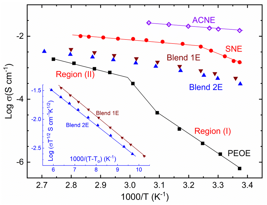 | ||
| Fig. 1 Logσ–T−1 plots of ACNE, SNE, Blends 1E & 2E, and PEOE. Inset showed logσT½–(T − To)−1 plots for Blends 1E & 2E. Please see the text for details of regions (I) and (II). | ||
Blends 1E & 2E illustrated the movement of segmental chains and the semi-random movement of small polymeric chains in amorphous domains through the downward logσ vs. T−1 curves.12,29,36,37 The amorphous domain has a characteristic temperature, To, the ideal vitreous transition temperature. Vogel–Tammann–Fulcher (VTF) used To in their empirical relation, σ = σoT−1/2exp[−B/kB(T − To)] to portray the downward curve. This relation had a notation B for the pseudo-activation energy. The inset of Fig. 1 shows the logσT½ vs. (T − To)−1 plot for Blends 1E & 2E. This plot demonstrated a linear trend for both mediators. Blends 1E & 2E had a similar slope value and, thereby, the B-value (≈0.06 eV). The B-value is comparable to those obtained for the PEO–SN blend-based I−/I3− and Co2+/Co3+ redox mediators.27,44,45 This indicates easy ion transport as in liquid electrolytes. Also, Blends 1E & 2E possessed a B-value < 0.3 eV, a requirement for DSSC application.
Fig. 2 exhibits XRD curves of SNE, Blends 1E & 2E, and PEOE. SNE and PEOE showed XRD patterns resembling those of the matrix, SN, and PEO, respectively, though the reflection peaks were relatively weak and broad.42,44 This indicates a disorder in molecules of succinonitrile and polymeric chains of poly(ethylene oxide) induced by the large size of ions.34,36,42,44,45 Furthermore, the lack of distinctive peaks of the ionic salts in the XRD profiles of SNE and PEOE suggested a complete dissociation of the salts. The XRD profiles of Blends 1E & 2E possessed none of the distinctive peaks of the constituents. The lack of peaks indicated the complete amorphous phase formation, as observed earlier for the (PEO–SN)–MI–I2 and (PEO–SN)–LiX solid electrolytes, where M = Li and K, and X = TFSI and ClO4.44,45,48–50 The absence of peaks is due to an interaction between succinonitrile molecules, poly(ethylene oxide) chains, and ions.49,50 One can also note a difference in hump position with a 2θ-value higher for the more conductive electrolyte (Blend 1E), as observed earlier for a similar system.27 This is probably due to a better solvation of the ions with the CH2–CH2–O chains of the PEO in the presence of succinonitrile molecules, resulting in more amorphicity for the Blend 1E. The findings were supported by FT-IR spectroscopy, UV-vis, POM, SEM, and DSC investigations.
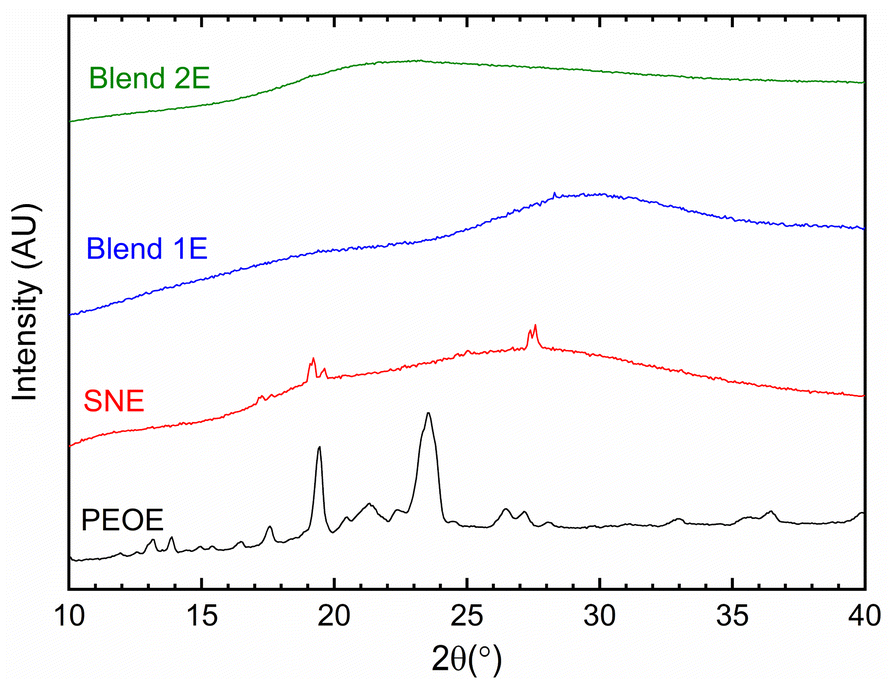 | ||
| Fig. 2 XRD curves of SNE, Blends 1E & 2E, and PEOE. | ||
Fig. 3 exhibits FT-IR spectra of SNE, Blends 1E & 2E, PEOE, and ACNE redox mediators, along with the cobalt and lithium salts in fingerprint, νC![[triple bond, length as m-dash]](https://www.rsc.org/images/entities/char_e002.gif) N, and νC–H regions for comparison. Table S1† presented the vibrational frequencies and their assignments for redox mediators, acetonitrile,51 succinonitrile,42,44,45,52 PEO,42,44,45,53 succinonitrile–PEO blend,42,44,45 LiCF3SO3,54–56 and Co(bpy)3(TFSI)2.48,57–59 Bernson and Lindgren54 observed the presence of CF3SO3− ions via νs,SO3 mode at 1032 cm−1 (free ions) and 1040 cm−1 (coordinated ions), νa,CF3 mode at 1156 cm−1 (free) and 1165 cm−1 (coordinated), νs,CF3 mode at 1226 cm−1 (free), νa,SO3 mode at 1258 cm−1 (coordinated), 1272 cm−1 (free), and 1300 cm−1 (coordinated) for the 0.05 M LiCF3SO3 solution in acetonitrile. Rhodes and Frech56 observed the δa,SO3 mode at 521 and 576 cm−1, δa,CF3 mode at 582 and 588 cm−1, δs,SO3 mode at 641 cm−1, δs,CF3 mode at 761 and 766 cm−1, and νs,SO3 mode at 1044 cm−1 in the infrared spectrum of the PEO3LiCF3SO3 polymer electrolyte through a symmetry-based analysis. The position and intensity of a mode were dependent on salt concentration because of the formation of free and coordinated ions. The same was observed for the poly(propylene oxide)–LiCF3SO3 polymer electrolyte.54,55 Though the formation of coordinated ions decreases the number of free ions, this results in increasing the mobility in the polar polymer, reducing the solvent–salt interaction, and, thereby increasing the amorphicity in the electrolyte.58 In the present case, the CF3SO3− modes have overlapped with those of the relatively stronger TFSI− modes because of the higher concentration of TFSI−, making extraction of any information regarding the matrix–CF3SO3− interaction difficult. The observed matrix–TFSI− interaction in the fingerprint, νCN, and νCH regions has been discussed below. It is noteworthy that the strongly solvated free and unpaired TFSI− ion results in peaks at 1057, 1133, 1196, and 1351 cm−1; whereas the coordinated TFSI− ion produces peaks at 1229 and 1331 cm−1.48,58,59
N, and νC–H regions for comparison. Table S1† presented the vibrational frequencies and their assignments for redox mediators, acetonitrile,51 succinonitrile,42,44,45,52 PEO,42,44,45,53 succinonitrile–PEO blend,42,44,45 LiCF3SO3,54–56 and Co(bpy)3(TFSI)2.48,57–59 Bernson and Lindgren54 observed the presence of CF3SO3− ions via νs,SO3 mode at 1032 cm−1 (free ions) and 1040 cm−1 (coordinated ions), νa,CF3 mode at 1156 cm−1 (free) and 1165 cm−1 (coordinated), νs,CF3 mode at 1226 cm−1 (free), νa,SO3 mode at 1258 cm−1 (coordinated), 1272 cm−1 (free), and 1300 cm−1 (coordinated) for the 0.05 M LiCF3SO3 solution in acetonitrile. Rhodes and Frech56 observed the δa,SO3 mode at 521 and 576 cm−1, δa,CF3 mode at 582 and 588 cm−1, δs,SO3 mode at 641 cm−1, δs,CF3 mode at 761 and 766 cm−1, and νs,SO3 mode at 1044 cm−1 in the infrared spectrum of the PEO3LiCF3SO3 polymer electrolyte through a symmetry-based analysis. The position and intensity of a mode were dependent on salt concentration because of the formation of free and coordinated ions. The same was observed for the poly(propylene oxide)–LiCF3SO3 polymer electrolyte.54,55 Though the formation of coordinated ions decreases the number of free ions, this results in increasing the mobility in the polar polymer, reducing the solvent–salt interaction, and, thereby increasing the amorphicity in the electrolyte.58 In the present case, the CF3SO3− modes have overlapped with those of the relatively stronger TFSI− modes because of the higher concentration of TFSI−, making extraction of any information regarding the matrix–CF3SO3− interaction difficult. The observed matrix–TFSI− interaction in the fingerprint, νCN, and νCH regions has been discussed below. It is noteworthy that the strongly solvated free and unpaired TFSI− ion results in peaks at 1057, 1133, 1196, and 1351 cm−1; whereas the coordinated TFSI− ion produces peaks at 1229 and 1331 cm−1.48,58,59
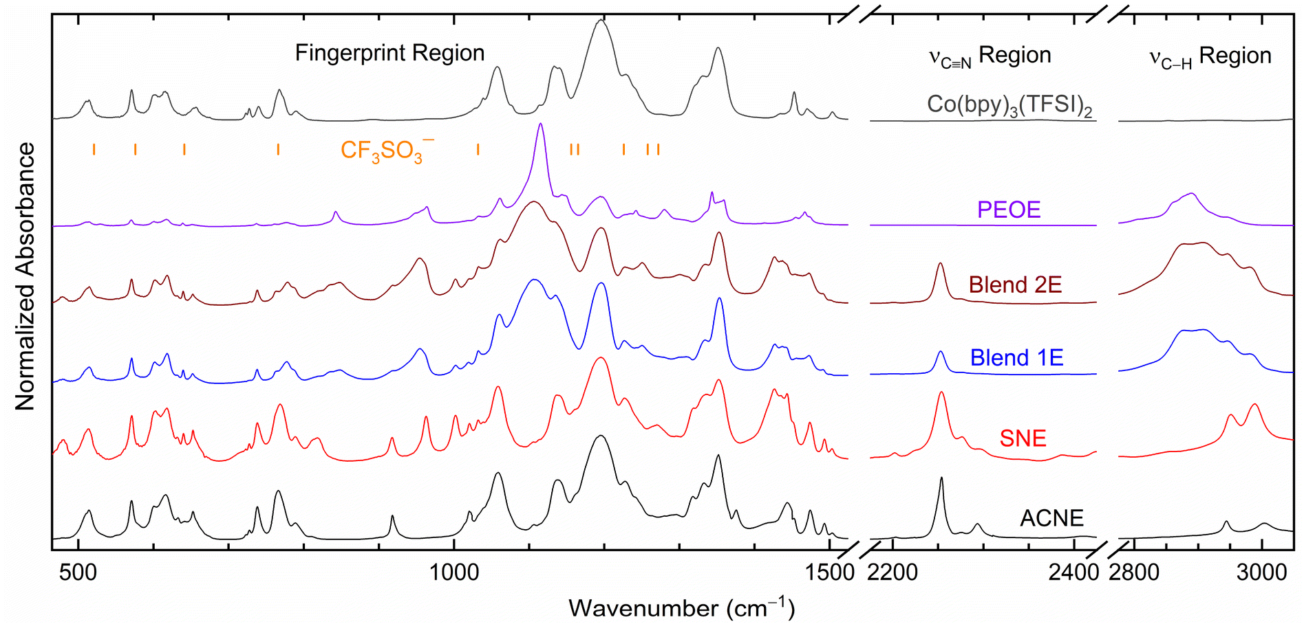 | ||
| Fig. 3 FT-IR spectra of ACNE, SNE, Blends 1E & 2E, and PEOE, including Co(bpy)3(TFSI)2 salt. Vertical lines, CF3SO3− ions. | ||
ACNE observed an insignificant change in the position of the modes of the TFSI− ion and bpy ligand, indicating a complete dissociation of ionic salts by the ACN, resulting in a vast number of free ions. The ACNE spectrum also showed weak coordinated peaks at 1229 and 1331 cm−1 as shoulders, indicating the presence of a few ion pairs. Thus, ACNE had many free ions for transport, resulting in σ25°C ≈ 10−2 S cm−1.
SNE showed the spectrum comprising modes of the constituents without a substantial alter in the position in all regions except for the bpy ring position at 1443 (1453 cm−1) and 1474 (1470 cm−1). Like the ACNE, the SNE showed weak coordinated TFSI− peaks as shoulders. These observations reveal a complete dissociation of ionic salts by the SN in SNE, thereby creating many free ions for transport along with a few ion pairs. However, the succinonitrile–bpy interaction hinders the ion transport, resulting in σ25°C ≈ 10−3 S cm−1.
PEOE demonstrated the PEO–salt interaction through a shift in the position of several modes in the fingerprint region only. The changes were at 651 (656 cm−1, δa,SO3), 737 (740 cm−1, νs,SNS), 777 (767 cm−1, bpy ring), 1115 (1109 cm−1, νs,COC), 1144 (1133 cm−1, νs,SO2; 1149 cm−1, νCC), and 1343 (1351 cm−1, νa,SO2). This interaction most probably hindered the transport of ions, resulting in poor σ25°C-value, 6.3 × 10⁻⁷ S cm−1. The spectrum of the PEOE also showed a very sharp νs,COC mode at 1115 cm−1 with two shoulder peaks, νa,COC mode at 1061 cm−1 and νCC mode at 1144 cm−1, revealing the crystalline nature of the PEOE.42,44,45,53
Blends 1E & 2E demonstrated their amorphous nature by displaying a broad νs,COC mode at 1106 cm−1 with a weak shoulder peak of the νa,COC mode at 1061 cm−1. Similar to SNE, the blend–bpy ring interaction can be visualized in the fingerprint region at 777 cm−1 (762 cm−1, δCH2; 767 cm−1, bpy-ring), 1437 (1453 cm−1, δCH2 and bpy ring), and 1473 (1469 cm−1, δCH2 and bpy ring), indicating the prominent role of succinonitrile in the interaction with the bpy ring. The blend–salt interaction also resulted in a blueshift in the νCH2 modes in the region, 2800–3100 cm−1, and ion paring peaks at ∼1227 and ∼1334 cm−1. As mentioned earlier, this shift is due to an increase in amorphicity.42,44,45,53 The Blend 1E observed marginally higher blueshift than the Blend 2E.
Fig. 4 demonstrates the solvent/matrix–salt interaction effect on intensity for the fingerprint region.27 This figure showed relative intensities ΔI1 = I919 cm−1/I1196 cm−1 and ΔI2 = I1105 cm−1/I1196 cm−1 for redox mediators, where I stands for intensity at 919 cm−1 for νs,C–CN mode of acetonitrile/succinonitrile; at 1105 cm−1 for νs,COC mode of PEO; and at ∼1196 cm−1 for the νa,CF3 mode of ionic salts. The I919 cm−1 had the trend of PEOE (=0) ≪ Blend 1E < Blend 2E < SNE ≈ ACNE. The I1196 cm−1 had the trend: PEOE ≪ Blend 2E < Blend 1E ≈ SNE ≈ ACNE. These resulted in ΔI1 with a trend: PEOE (=0) ≪ Blend 1E ≪ Blend 2E ≈ SNE ≈ ACNE. As observed earlier, the high value of ΔI1 indicates a low level of nitrile–salt interaction. Also, ΔI1(Blend 2E) ≈ 2 × ΔI1(Blend 1E), revealing a role of concentration of salt because EO/Li+(Blend 2E) = 2 × EO/Li+(Blend 1E). Thus, the higher salt concentration of Blend 1E led to more ion pairs, thereby higher polymeric flexibility and amorphicity. The ΔI2 provided a similar statement, too. The I1105 cm−1 had the following trend: PEOE (=1) = Blend 2E = Blend 1E ≫ SNE = ACNE (=0), which resulted in ΔI2 with a trend: PEOE ≫ Blend 2E > Blend 1E ≫ SNE = ACNE (=0). This trend revealed that the interaction between PEO and salt, thereby PEO crystallinity, is low for the Blends 1E & 2E, and high for the PEOE. The UV-vis, POM, and SEM studies, which have been covered below, corroborate these results.
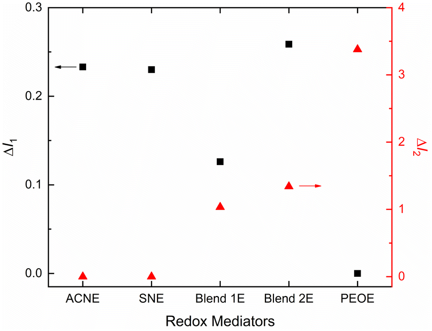 | ||
| Fig. 4 Relative intensities: ΔI1 and ΔI2 of ACNE, SNE, Blends 1E & 2E, and PEOE. | ||
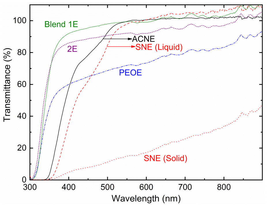
Fig. 5 shows the transmittance spectra of ACNE, SNE (liquid and solid), Blends 1E & 2E, and PEOE. The transmittance values at 350 nm (UV-A region) and 555 nm (visible region) are as follows. UV-A region: ∼3.3% (ACNE), 0.5% (SNE_liquid), 0% (SNE_solid), 66.6% (Blend 1E), 68.8% (Blend 2E), and 45.4% (PEOE). Visible region: ∼99.9% (ACNE), 99.5% (SNE_liquid), 15.1% (SNE_solid), 99% (Blend 1E), 91.8% (Blend 2E), and 71.9% (PEOE). The transparency of the PEO-based electrolytes demonstrated the order as Blend 1E > Blend 2E ≫ PEOE. As discussed later, this is due to the level of PEO crystallinity, which is the lowest for Blend 1E and the highest for PEOE.45 It is important to mention that only Blend 1E demonstrated a significant level of transparency across all wavelengths, suggesting its possible suitability for use in the device. These results corroborate the POM results discussed below.
 | ||
| Fig. 5 Transmittance spectra of ACNE, SNE (liquid and solid), Blends 1E & 2E, and PEOE. | ||
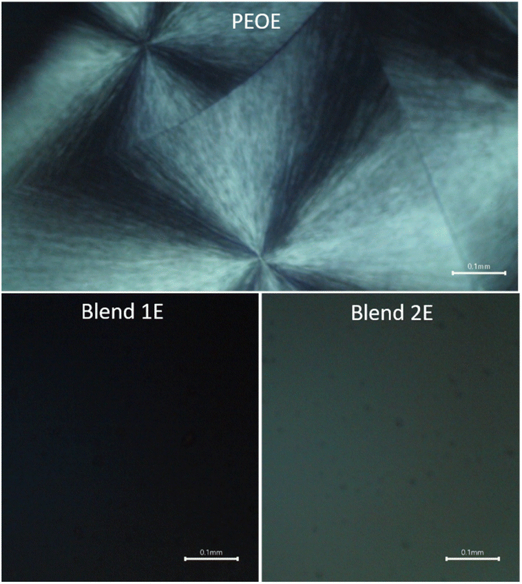
Fig. 6 portrays POM images of the PEO-based redox mediators: PEOE, Blend 1E, and Blend 2E. The image of the PEOE showed diamond-like spherulites as well as dark regions. Short, randomly oriented PEO chains result in the former, while the amorphous domain accounts for the latter.44,45 The abundance of spherulites in the amorphous regions indicates a high degree of crystallinity in PEO, which is the key factor contributing to the poor electrical conductivity of PEOE. The Blends 1E & 2E did not show any spherulite, indicating the arrest of the amorphous phase.
 | ||
| Fig. 6 POM images of PEO-based redox mediators: PEOE, Blend 1E, and Blend 2E. Scale bar: 0.1 mm. | ||
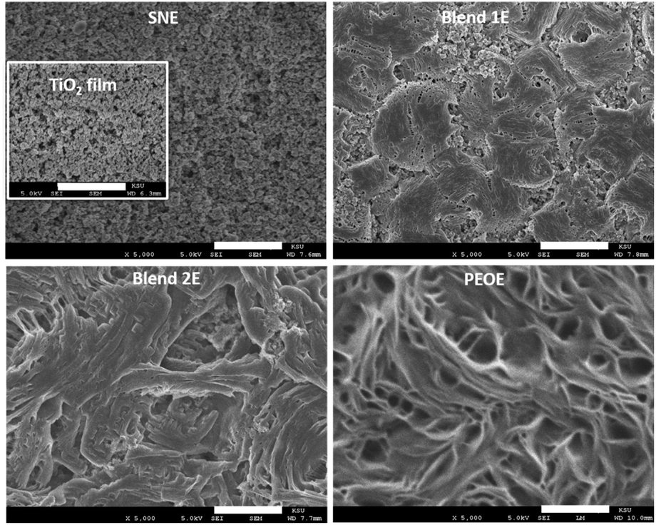
Fig. 7 shows SEM images of mesoporous TiO2 film filled with a solid redox mediator (SNE, Blends 1E & 2E, and PEOE) and an image of a bare mesoporous TiO2 film as an inset for direct comparison. Having a solid solvent (succinonitrile), SNE impregnated the nanopores of the TiO2 film well. The Blend 1E resulted in a smoother surface than the Blend 2E. According to the FT-IR spectroscopy analysis (Fig. 4), Blend 1E shows increased polymeric flexibility and amorphicity because of its elevated salt content, leading to a higher number of ion pairs. The PEOE exhibited a coarse surface characterized by many fibril-like features, suggesting a high concentration of PEO chains. The DSC study corroborates these findings and is addressed below.
 | ||
| Fig. 7 SEM images of SNE, Blends 1E & 2E, and PEOE on mesoporous TiO2 film (inset). Scale bar: 5 μm. | ||
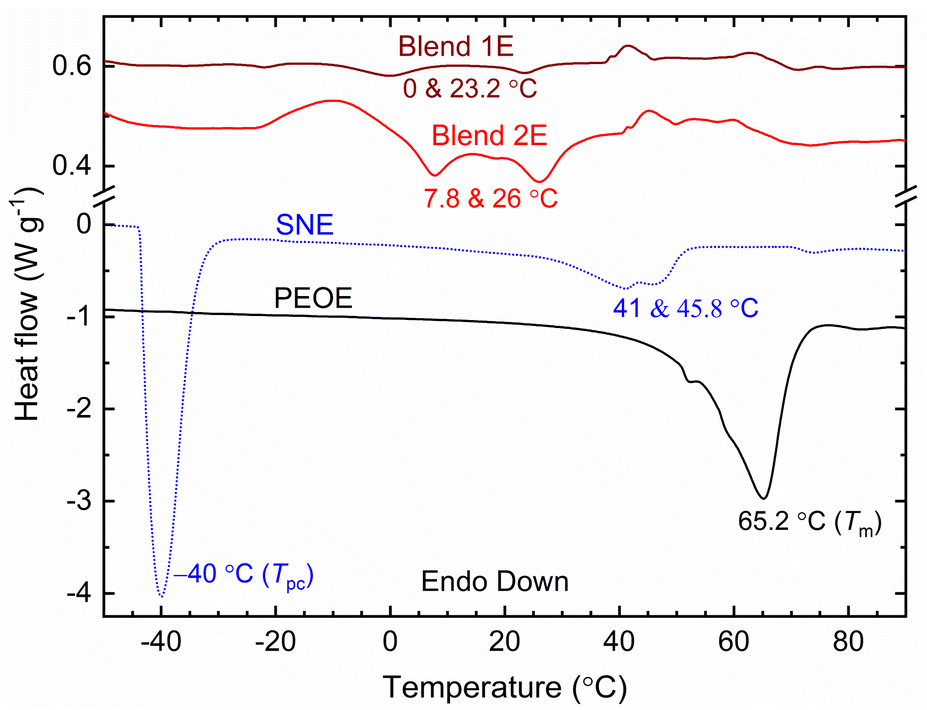
Fig. 8 displays DSC curves of SNE, Blends 1E & 2E, and PEOE solid redox mediators. The endothermic peak, corresponding to Tm of the redox mediator, emerged at 41 and 45.8 °C for SNE, 0 and 23.2 °C for Blend 1E, 7.8 and 26 °C for Blend 2E, and 65.2 °C for PEOE. The Tm-value was 58 °C for SN,34 30 °C for PEO–SN blend,42 and 66 °C for PEO,42 revealing that the redox mediator had a lower Tm-value than its matrix. The SN-based electrolytes also exhibited weak multiplets. The existence of the multiplet indicates the formation of a solid solution and/or a liquid eutectic phase by the SN–salt interaction.30 The multiplet increases the amorphicity. The solid solution and eutectic phase contain free ions, too. We calculated the crystallinity of the PEO-based redox mediators and noted 0.7% for Blend 1E, 2.3% for Blend 2E, and 72.1% for PEOE, controlling the conductivity value Blend 1E > Blend 2E ≫ PEOE.42–45 The SNE had an endothermic peak at −40 °C, too. This peak is the crystal-to-plastic crystal phase transition temperature (Tpc) of the matrix.34 The lack of the Tpc peak for the Blends 1E & 2E revealed the blend–salt interaction.42–45
 | ||
| Fig. 8 DSC curves of SNE, Blends 1E & 2E, and PEOE. | ||
An initial plateau region of the TGA curve corresponds to the thermal stability of a solid.42 Fig. 9 shows the TGA curves of the SNE, Blends 1E & 2E, and PEOE, depicting the plateau nearly up to 75, 125, and 200 °C, respectively, and thus their thermal stability. SNE and PEOE portrayed a single-stage decomposition with a massive drop in mass at nearly 125 °C and 300 °C because of the matrix, respectively. Blends 1E & 2E, however, portrayed two-stage degradations because of the SN–PEO blend matrix.27 Because Blend 1E had a higher salt concentration than Blend 2E, the first-stage degradation occurred more slowly for Blend 1E.
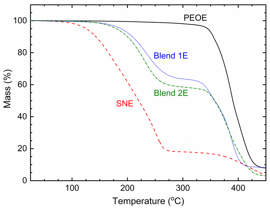 | ||
| Fig. 9 TGA curves of SNE, Blends 1E & 2E, and PEOE. | ||
Notably, the Co2+/Co3+ redox couple suffers from mass diffusion problems in DSSCs, resulting in poor η-value.60 The mass transport phenomenon in DSSC depends strongly on the porosity of mesoporous TiO2 film. Following the procedure of Yella et al.,60 we used 0.06 M TiCl4 aqueous solution for blocking layer of TiO2, screen printing of 18NRT paste (TiO2 particle size 18 nm), and screen printing of Ti-nanoxide R/SP paste (TiO2 particle size > 100 nm) on 15 Ω □−1 FTO glass for preparing nearly 6 μm mesoporous TiO2 film after sintering at 500 °C for 30 minutes. The TiO2 film was sensitized with a 0.2 mM solution of Y123 dye and chenodeoxycholic acid in a tetrahydrofuran–ethanol solvent mixture (1 to 4 volume ratio).60 This dye-sensitized TiO2 layer was infiltrated with a redox mediator and barricaded with a Meltonix (25 μm) film. This layer was covered with a platinum film on the FTO glass. The DSSC was subjected to a J–V study under simulated solar irradiation of 100 mW cm−2 using a PV measurement (USA) unit. Fig. 10 shows the J–V curves of ACNE, SNE, Blend 1E, and PEOE, which resulted in photovoltaic cell parameters, such as open-circuit voltage (VOC), short-circuit current density (JSC), fill factor (FF), and efficiency (η). Table 2 presented the photovoltaic cell parameters of ACNE, SNE, Blend 1E, and PEOE with η of 2.5, 1, 0.7, and 0.2%, respectively, adopting the σ25°C-value order: ACNE > SNE > Blend 1E > PEOE. Yella et al.60 achieved η ≈ 9.44% with 30 nm-sized TiO2 particles for a liquid redox mediator similar to ACNE. This shows a requirement of modification in the pore size of mesoporous TiO2 film by utilizing a larger size of anatase TiO2 particles.60–63
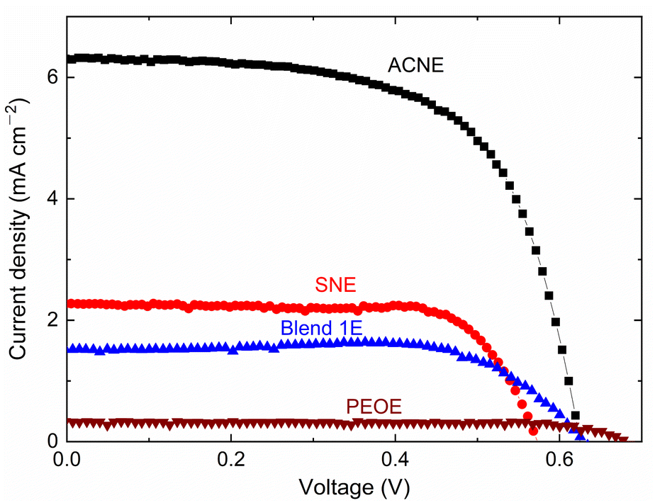 | ||
| Fig. 10 J–V curves of ACNE, SNE, Blend 1E, and PEOE at 25 °C and one sun. | ||
| Electrolyte | VOC (mV) | JSC (mA cm−2) | FF (%) | η (%) |
|---|---|---|---|---|
| ACNE | 624.8 | 6.3 | 64 | 2.52 |
| SNE | 572.9 | 2.3 | 74.2 | 0.97 |
| Blend 1E | 630.2 | 1.5 | 73.6 | 0.7 |
| PEOE | 680.3 | 0.3 | 79.5 | 0.18 |
Experimental
Synthesis
The chemicals, including the solvents used for the present study, are listed in Table S2.† The PEO had a molecular weight of 1 M g mol−1. Table S3† exhibits the composition of redox mediators. The ACNE and SNE solutions were prepared by dissolving 0.1 M LiCF3SO3, 0.25 M Co[tris-(2,2′-bipyridine)]3(TFSI)2, and 0.06 M Co[tris-(2,2′-bipyridine)]3(TFSI)3 in acetonitrile and succinonitrile, respectively.11 The mixture was stirred at 65 °C for 24 h. The solution cast method produced a self-standing film of the PEO-based redox mediators. A viscous and homogeneous polymeric solution was prepared via rigorous stirring followed by pouring on a Teflon-based Petri dish and drying at room temperature under nitrogen gas purging to produce a film. We used 20 ml of acetonitrile to dissolve the ingredients at 65 °C for 48 h. The film was further dried for 24 h in a vacuum desiccator.Characterizations
Conclusions
We produced solid redox mediators by combining [(1 − x)SN: xPEO], LiCF3SO3, and cobalt salts to study their electrical transport capabilities as potential substitutes for the liquid redox mediator (ACNE). The mediators SNE and PEOE, with x values of 0 and 1 respectively, showed electrical conductivity of 1.5 × 10⁻³ and 6.3 × 10⁻⁷ S cm−1 at 25 °C. These values are roughly one and four orders of magnitude lower than that of the ACNE (σ25°C ≈ 1.7 × 10⁻² S cm−1). Both mediators displayed Arrhenius-type characteristics akin to ACNE. The activation energy estimates for SNE and PEOE were 0.77 and 1.22 eV, respectively, which were greater than the 0.16 eV value for ACNE. PEOE showed a significant PEO crystallinity, 72.1%. Blends 1E & 2E exhibited electrical conductivity of 4.7 × 10⁻⁴ and 3.1 × 10⁻⁴ S cm−1, respectively, which are roughly two orders of magnitude lower than that of the ACNE. Blends 1E & 2E portrayed VTF-type behavior with a pseudo-activation energy of 0.06 V, which is lower than the 0.3 eV threshold needed for a device application. Blends 1E & 2E exhibited PEO crystallinity of 0.7% and 2.3%, respectively, and demonstrated thermal stability up to a temperature of 125 °C. Blend 1E exhibited elevated levels of electrical conductivity and UV-A-visible-near-infrared transmittance, while demonstrating reduced activation energy and PEO crystallinity. The results align with the discoveries made about the LiTFSI-based redox mediators.27 The results also demonstrated that incorporating ionic salts with large cations and anions into a succinonitrile–poly(ethylene oxide) blend is an effective approach for enhancing the electrical, optical, and thermal characteristics of a solid redox mediator for device applications.Author contributions
Conceptualization, R. K. G. and I. B.; methodology, R. K. G. and I. B.; formal analysis, R. K. G, H. S. and A. K.; investigation, R. K. G., H. S., A. I., A. K., R. A. and A. F. A.; writing—original draft preparation, R. K. G.; writing—review and editing, R. K. G., I. B. and A. S. A.; supervision, R. K. G.; project administration, R. K. G.; funding acquisition, R. K. G., I. B. and A. S. A.Conflicts of interest
There are no conflicts to declare.Acknowledgements
The Authors would like to extend their appreciation to the Deputyship for Research and Innovation “Ministry of Education” in Saudi Arabia for the financial support through the project (number IFKSUOR3-423-2).Notes and references
- B. O'Regan and M. Gratzel, Nature, 1991, 353, 737–740 CrossRef
.
- Y. Chiba, A. Islam, Y. Watanabe, R. Komiya, N. Koide and L. Y. Han, Jpn. J. Appl. Phys., Part 2, 2006, 45, L638–L640 CrossRef CAS
- M. A. Green, E. D. Dunlop, G. Siefer, M. Yoshita, N. Kopidakis, K. Bothe and X. Hao, Prog. Photovoltaics, 2023, 31, 3–16 Search PubMed
- A. Hagfeldt, G. Boschloo, L. C. Sun, L. Kloo and H. Pettersson, Chem. Rev., 2010, 110, 6595–6663 CrossRef CAS
- A. F. Nogueira, C. Longo and M. A. De Paoli, Coord. Chem. Rev., 2004, 248, 1455–1468 CrossRef CAS
- B. Li, L. D. Wang, B. N. Kang, P. Wang and Y. Qiu, Sol. Energy Mater. Sol. Cells, 2006, 90, 549–573 CrossRef CAS
- A. Yella, H. W. Lee, H. N. Tsao, C. Y. Yi, A. K. Chandiran, M. K. Nazeeruddin, E. W. G. Diau, C. Y. Yeh, S. M. Zakeeruddin and M. Gratzel, Science, 2011, 334, 629–634 CrossRef CAS PubMed
- P. K. Singh, R. K. Nagarale, S. P. Pandey, H. W. Rhee and B. Bhattacharya, Adv. Nat. Sci.: Nanosci. Nanotechnol., 2011, 2, 023002 Search PubMed
- M. K. Wang, C. Gratzel, S. M. Zakeeruddin and M. Gratzel, Energy Environ. Sci., 2012, 5, 9394–9405 RSC
- J. Y. Cong, X. C. Yang, L. Kloo and L. C. Sun, Energy Environ. Sci., 2012, 5, 9180–9194 RSC
- S. Mathew, A. Yella, P. Gao, R. Humphry-Baker, B. F. E. Curchod, N. Ashari-Astani, I. Tavernelli, U. Rothlisberger, M. K. Nazeeruddin and M. Gratzel, Nat. Chem., 2014, 6, 242–247 CrossRef CAS PubMed
- J. H. Wu, Z. Lan, J. M. Lin, M. L. Huang, Y. F. Huang, L. Q. Fan and G. G. Luo, Chem. Rev., 2015, 115, 2136–2173 CrossRef CAS PubMed
- L. Giribabu, R. Bolligarla and M. Panigrahi, Chem. Rec., 2015, 15, 760–788 CrossRef CAS PubMed
- F. Bella, S. Galliano, C. Gerbaldi and G. Viscardi, Energies, 2016, 9, 384 CrossRef
- M. Freitag, J. Teuscher, Y. Saygili, X. Zhang, F. Giordano, P. Liska, J. Hua, S. M. Zakeeruddin, J. E. Moser, M. Gratzel and A. Hagfeldt, Nat. Photonics, 2017, 11, 372–378 CrossRef CAS
- S. Venkatesan and Y. L. Lee, Coord. Chem. Rev., 2017, 353, 58–112 CrossRef CAS
- H. Iftikhar, G. G. Sonai, S. G. Hashmi, A. F. Nogueira and P. D. Lund, Materials, 2019, 12, 1998 CrossRef CAS PubMed
- N. Vlachopoulos, A. Hagfeldt, I. Benesperi, M. Freitag, G. Hashmi, G. B. Jia, R. A. Wahyuono, J. Plentz and B. Dietzek, Sustainable Energy Fuels, 2021, 5, 367–383 RSC
- K. S. Srivishnu, S. Prasanthkumar and L. Giribabu, Mater. Adv., 2021, 2, 1229–1247 RSC
- M. Kokkonen, P. Talebi, J. Zhou, S. Asgari, S. A. Soomro, F. Elsehrawy, J. Halme, S. Ahmad, A. Hagfeldt and S. G. Hashmi, J. Mater. Chem. A, 2021, 9, 10527–10545 RSC
- L. Zhang, X. C. Yang, W. H. Wang, G. G. Gurzadyan, J. J. Li, X. X. Li, J. C. An, Z. Yu, H. X. Wang, B. Cai, A. Hagfeldt and L. C. Sun, ACS Energy Lett., 2019, 4, 943–951 CrossRef CAS
- K. Kakiage, Y. Aoyama, T. Yano, K. Oya, J. Fujisawa and M. Hanaya, Chem. Commun., 2015, 51, 15894–15897 RSC
- T. Stergiopoulos, M. Bidikoudi, V. Likodimos and P. Falaras, J. Mater. Chem., 2012, 22, 24430–24438 RSC
- S. Venkatesan, I. P. Liu, L. T. Chen, Y. C. Hou, C. W. Li and Y. L. Lee, ACS Appl. Mater. Interfaces, 2016, 8, 24559–24566 CrossRef CAS PubMed
- S. Venkatesan, I. P. Liu, C. M. T. Shan, H. S. Teng and Y. L. Lee, Chem. Eng. J., 2020, 394, 124954 CrossRef CAS
- P. Karthika, S. Ganesan, A. Thomas, T. M. S. Rani and M. Prakash, Electrochim. Acta, 2019, 298, 237–247 CrossRef CAS
- R. K. Gupta, H. Shaikh, A. Imran, I. Bedja, A. F. Ajaj and A. S. Aldwayyan, Polymers, 2022, 14, 1870 CrossRef CAS PubMed
- R. Younesi, G. M. Veith, P. Johansson, K. Edström and T. Vegge, Energy Environ. Sci., 2015, 8, 1905–1922 RSC
- A. Arya and A. L. Sharma, J. Mater. Sci., 2020, 55, 6242–6304 CrossRef CAS
- P. J. Alarco, Y. Abu-Lebdeh, A. Abouimrane and M. Armand, Nat. Mater., 2004, 3, 476–481 CrossRef CAS PubMed
- P. Wang, Q. Dai, S. M. Zakeeruddin, M. Forsyth, D. R. MacFarlane and M. Gratzel, J. Am. Chem. Soc., 2004, 126, 13590–13591 CrossRef CAS PubMed
- Q. Dai, D. R. MacFarlane and M. Forsyth, Solid State Ionics, 2006, 177, 395–401 CrossRef CAS
- Z. G. Chen, H. Yang, X. H. Li, F. Y. Li, T. Yi and C. H. Huang, J. Mater. Chem., 2007, 17, 1602–1607 RSC
- R. K. Gupta, I. Bedja, A. Islam and H. Shaikh, Solid State Ionics, 2018, 326, 166–172 CrossRef CAS
- R. K. Gupta, H. Shaikh and I. Bedja, ACS Omega, 2020, 5, 12346–12354 CrossRef CAS PubMed
- P. G. Bruce and F. M. Gray, in Solid State Electrochemistry, ed. P. G. Bruce, Cambridge University Press Cambridge, United Kingdom, 1995, ch. 6, pp. 119–162 Search PubMed
- R. C. Agrawal and G. P. Pandey, J. Phys. D: Appl. Phys., 2008, 41, 223001 CrossRef
- C. Reichardt, Solvents and Solvent Effects in Organic Chemistry, WILEY-VCH Verlag GmbH & Co. KGaA, Weinheim, 3 edn, 2003, pp. 23–26 Search PubMed
- CRC Handbook of Chemistry and Physics, ed. D. R. Lide, CRC Press/Taylor and Francis, Boca Raton, FL, USA, 2009, pp. 3–6 Search PubMed
- B. Bhattacharya, J. Y. Lee, J. Geng, H. T. Jung and J. K. Park, Langmuir, 2009, 25, 3276–3281 CrossRef CAS PubMed
- R. K. Gupta and I. Bedja, J. Phys. D: Appl. Phys., 2017, 50, 245501 CrossRef
- R. K. Gupta, H. M. Kim and H. W. Rhee, J. Phys. D: Appl. Phys., 2011, 44, 205106 CrossRef
- R. K. Gupta and H. W. Rhee, Adv. OptoElectron., 2011, 2011, 102932 Search PubMed
- R. K. Gupta and H. W. Rhee, Electrochim. Acta, 2012, 76, 159–164 CrossRef CAS
- R. K. Gupta and H. W. Rhee, J. Phys. Chem. B, 2013, 117, 7465–7471 CrossRef CAS PubMed
- M. Patel and A. J. Bhattacharyya, Electrochem. Commun., 2008, 10, 1912–1915 CrossRef CAS
- R. C. Agrawal and R. K. Gupta, J. Mater. Sci., 1999, 34, 1131–1162 CrossRef CAS
- R. K. Gupta and H. W. Rhee, Bull. Korean Chem. Soc., 2017, 38, 356–363 CrossRef CAS
- L. Z. Fan, Y. S. Hu, A. J. Bhattacharyya and J. Maier, Adv. Funct. Mater., 2007, 17, 2800–2807 CrossRef CAS
- R. J. Yue, Y. H. Niu, Z. G. Wang, J. F. Douglas, X. Q. Zhu and E. Q. Chen, Polymer, 2009, 50, 1288–1296 CrossRef CAS
- E. L. Pace and L. J. Noe, J. Chem. Phys., 1968, 49, 5317–5325 CrossRef CAS
- O. I. Fengler and A. Ruoff, Spectrochim. Acta, Part A, 2001, 57, 105–117 CrossRef CAS PubMed
- T. Yoshihara, H. Tadokoro and S. Murahashi, J. Chem. Phys., 1964, 41, 2902–2911 CrossRef CAS
- A. Bernson and J. Lindgren, Solid State Ionics, 1993, 60, 37–41 CrossRef CAS
- W. Huang, R. Frech and R. A. Wheeler, J. Phys. Chem., 1994, 98, 100–110 CrossRef CAS
- C. P. Rhodes and R. Frech, Solid State Ionics, 2000, 136–137, 1131–1137 CrossRef CAS
- E. Castellucci, L. Angeloni, N. Neto and G. Sbrana, Chem. Phys., 1979, 43, 365–373 CrossRef CAS
- S. J. Wen, T. J. Richardson, D. I. Ghantous, K. A. Striebel, P. N. Ross and E. J. Cairns, J. Electroanal. Chem., 1996, 408, 113–118 CrossRef
- I. Rey, J. C. Lassègues, J. Grondin and L. Servant, Electrochim. Acta, 1998, 43, 1505–1510 CrossRef CAS
- A. Yella, S. Mathew, S. Aghazada, P. Comte, M. Gratzel and M. K. Nazeeruddin, J. Mater. Chem. C, 2017, 5, 2833–2843 RSC
- D. Hwang, H. Lee, S. Y. Jang, S. M. Jo, D. Kim, Y. Seo and D. Y. Kim, ACS Appl. Mater. Interfaces, 2011, 3, 2719–2725 CrossRef CAS PubMed
- D. Hwang, D. Y. Kim, S. Y. Jang and D. Kim, J. Mater. Chem. A, 2013, 1, 1228–1238 RSC
- M. Alduraibi, M. Hezam, B. Al-Ruhaimi, A. M. El-Toni, A. Algarni, M. Abdel-Rahman, W. Qing and A. Aldwayyan, Nanomaterials, 2020, 10, 413 CrossRef CAS PubMed
Footnote |
| † Electronic supplementary information (ESI) available. See DOI: https://doi.org/10.1039/d3ra07314a |
| This journal is © The Royal Society of Chemistry 2024 |