DOI:
10.1039/D3RA06803J
(Paper)
RSC Adv., 2024,
14, 353-363
Bacterial templated carbonate mineralization: insights from concave-type crystals induced by Curvibacter lanceolatus strain HJ-1
Received
6th October 2023
, Accepted 11th December 2023
First published on 2nd January 2024
Abstract
The elucidation of carbonate crystal growth mechanisms contributes to a deeper comprehension of microbial-induced carbonate precipitation processes. In this research, the Curvibacter lanceolatus HJ-1 strain, well-known for its proficiency in inducing carbonate mineralization, was employed to trigger the formation of concave-type carbonate minerals. The study meticulously tracked the temporal alterations in the culture solution and conducted comprehensive analyses of the precipitated minerals' mineralogy and morphology using advanced techniques such as X-ray diffraction, scanning electron microscopy, focused ion beam, and transmission electron microscopy. The findings unequivocally demonstrate that concave-type carbonate minerals are meticulously templated by bacterial biofilms and employ calcified bacteria as their fundamental structural components. The precise morphological evolution pathway can be delineated as follows: initiation with the formation of bacterial biofilms, followed by the aggregation of calcified bacterial clusters, ultimately leading to the emergence of concave-type minerals characterized by disc-shaped, sunflower-shaped, and spherical morphologies.
Introduction
Microbially Induced Carbonate Precipitation (MICP) is one of the important biogeochemical processes on the Earth surface.1 Microbially induced carbonate minerals play a common and important role in carbonate precipitation processes in both marine and freshwater environments.2 Studies have shown that MICP in nature can sequester atmospheric CO2 and contribute significantly to the global carbon cycle by mineral trapping.3–5 Moreover, MICP research has gained widespread attention in various fields due to its potential applications, including the restoration of damaged stone cultural heritage,6,7 enhancement of the resilience and durability of concrete structures,8,9 microbial remediation of heavy metal-contaminated soils and water,5,10,11 stabilization of soils and sandy substrates,12–14 and the exploration of extraterrestrial life based on the unique morphological characteristics of minerals.15,16
In order to investigate the mechanisms of bacteria-induced carbonate precipitation, scientists have conducted numerous biomineralization experiments using different microorganisms, including sulfate-reducing bacteria,17 anaerobic bacteria,18 urea hydrolyzing bacteria,19,20 thermophilic bacteria,21 and cyanobacteria.22,23 The aforementioned studies indicate that in bacteria-induced carbonate precipitation systems, bacteria influence/regulate the carbonate precipitation process through several aspects: bacterial activities can alter the physicochemical properties of the solution. Firstly, bacterial activities can increase the pH of the solution, providing a prerequisite for carbonate precipitation.24 Secondly, bacterial respiration can supply CO2 to the system, and the carbonic anhydrase (CA) secreted by bacteria can promote CO2 hydration and create locally supersaturated microenvironments favorable for crystal nucleation.4,25 Besides, bacterial cells and their secreted extracellular polymeric substances (EPS) can provide nucleation sites for CaCO3. As heterogeneities in the system, bacterial cells can effectively lower interfacial energy,23,26–28 and their negatively charged organic functional groups (phosphate, sulfate, carboxylate, etc.) on the surface can adsorb cations from the solution, facilitating mineral nucleation on their surfaces.29,30 The EPS secreted by bacteria can not only adsorb cations from the solution through its negatively charged functional groups but also promote non-classical crystallization pathways through multi-step precursor routes, thereby influencing the morphology of the mineral.31,32 Studies have shown that insoluble matrices in the solution are likely to serve as effective heterogeneous nucleation sites.17,33 These insoluble matrices can be composed of macromolecules, which provide frameworks and scaffolds for mineral deposition.31 Membrane proteins, acidic polysaccharides, and amino acids on the bacterial cell surface, which are negatively charged organic substances, can adsorb metal cations such as Ca2+ and Mg2+ from the solution, leading to their accumulation on the cell surface.34–37
Compared to carbonate minerals synthesized in chemical systems, microbial-induced carbonate minerals exhibit a greater diversity of morphologies.38 In studies on MICP process, rod-shaped minerals of varying sizes are frequently observed. Due to their similarity in size and shape to bacteria, these minerals are often presumed to be formed after bacterial calcification. However, conclusions based solely on morphological observations often lack supporting microscale evidence, especially when such morphologies are common in both biological and abiotic systems. Similarly, dumbbell-shaped carbonate minerals are one of the common distinctive morphologies associated with microbial precipitation, characterized by large ends (often resembling spheres) and a small middle portion. There are various explanations regarding the formation mechanism of dumbbell-shaped carbonate minerals, but it is difficult to draw convincing conclusions based solely on morphological observations. In addition, spherical, hemispherical, platy, columnar, conical, cross-shaped, cauliflower-shaped, and irregular mineral aggregates are also commonly observed in microbial mineralization systems, and there seems to be a growth relationship between these different morphologies.35,39,40
Until now, the evolution of mineral morphology has been overlooked in the realm of MICP mechanisms, with relatively scant studies devoted to comprehending this aspect. The morphology of bacterially induced carbonate minerals is influenced by diverse physicochemical and biological factors, encompassing temperature, pH value, bacterial species, and secretions. Consequently, even under identical conditions, distinct bacteria can yield carbonate minerals with a wide array of shapes. Among the myriad influencing factors, the disparities in culture mediums have been widely recognized for their impact on carbonate mineral morphology, often manifesting in the form of biofilms. To explore the impact of bacterial biofilms on carbonate mineral morphology, the Curvibacter lanceolatus HJ-1 strain was chosen to conduct a 30 day MICP experiment. The HJ-1 strain has been reported multiple times for its mineralization-inducing capabilities, consistently showcasing a concave-type morphology in carbonate minerals in these reports.41,42 Through the measurement and observation of solid–liquid indicators, this study unraveled the solution conditions, nucleation mechanism, and crystallization sequence inherent in the MICP process. Additionally, it delved into discussing the growth mechanism of concave-type carbonate minerals using bacterial biofilms as templates, thereby offering novel insights into the nucleation and growth mechanisms of biogenic carbonate minerals.
Materials and methods
Sample preparation
A non-pathogenic Curvibacter lanceolatus HJ-1 strain was isolated from a soil sample collected at the Pai Lou Experimental station of Nanjing Agricultural University. By utilizing 16S rRNA gene sequencing and constructing a phylogenetic tree based on the sequence, it was determined that the HJ-1 strain belongs to the Curvibacter lanceolatus. The basic characteristics of the colony of this strain are as follows: it is transparent and raised, with a smooth surface and neat edges. The basic features of the bacterial cells are as follows: they are rod-shaped, with a diameter of approximately 0.5 μm. The length of the bacterial cells in their juvenile stage is about 1.5 μm, while mature cells can reach a length of 2–3 μm. The cell morphology is slightly curved (refer to Fig. 1). Gram staining of the bacterial cells shows a negative reaction (G−), indicating that the strain is Gram-negative. Additionally, the strain possesses flagella.
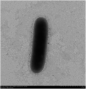 |
| | Fig. 1 Morphological investigation of Curvibacter lanceolatus HJ-1 strain.41 | |
The mineralization experiment was maintained for 30 days, with meticulous sampling at 12 different time points. We diligently collected samples every two days from day 0 to day 20, and then spaced them out to every five days until day 30. To kickstart the process, we first cultivated the strain on agar plates for a full 24 hours. With utmost care, we handpicked four vigorous colonies and transferred them into a mineralization medium enriched with a high concentration of calcium ions (0.05 mol L−1, a deliberate boost to accelerate the study). The concoction was then incubated in a reliable, temperature-controlled shaking incubator set at a steady 25 °C for another day, allowing the bacteria to multiply and prime themselves for action. Concurrently, we meticulously dispensed the sterilized medium into 36 trusty 150 mL erlenmeyer flasks, carefully pouring 90 mL into each flask. Three vials were carefully inoculated with 10 mL of the precious bacterial culture, hermetically sealed with parafilm, and placed in a precisely regulated 30 °C incubator, creating an ideal environment for the crucial MICP experiment. After each sampling session, we performed a meticulous separation process using centrifugation (at 5000 rpm for 5 minutes), separating the suspension into its distinct solid and liquid phases. The precious precipitate was then delicately spread onto glass microscope slides for thorough drying after an ethereal encounter with ethanol for dehydration.
Analytical methods
Measurement of pH value, Ca2+ concentration, bacterial density EPS content, CA activity and weight of precipitates. The pH value of every sample was measured with a pH meter (pHS-3C, Yoke Instrument, Shanghai, China) and the plate counting method was used to count bacterial density in each sample before centrifugation. After centrifugation, the supernatant of every sample was collected, a Thermo-6000 ICP-OES (inductively coupled plasma optical emission spectrometer) was used to measure Ca2+ concentration. The contents of extracellular polysaccharide and CA activity of every sample points were determined by phenol-sulfuric acid method and p-nitrophenol methods.42–44 The 30% H2O2 was applied to remove the organics from the precipitates, the weight of precipitates before and after H2O2 oxidation were recorded respectively.
Powder X-ray diffraction (XRD). The precipitates were deposited on a glass slide after dehydration with ethanol and air dried. Each sample was continuously scanned at 2° min−1 from 10° to 60° (2θ) at 35 kV and 20 mA in 0.01° (2θ) steps by an X-ray diffractometer (D/max-B III, Rigaku, Beijing, China) with Cu-Kα radiation (with an error of <5%). Identification of mineral phases was performed using Jade 6.5 software.
Fourier transform infrared spectroscopy (FTIR). The precipitates were analyzed using a Tensor 27 Fourier transform infrared spectrophotometer (FT-IR) (Bruker, Ettlingen, Germany). The spectrometer was set to scan at 1 cm−1 resolution with a scan range of 4000–400 cm−1.
Field emission scanning electron microscopy (FE-SEM). A FEI field-emission scanning electron microscope was used to observe the morphologies of the precipitated minerals. A small amount of particles was placed on the stub using a toothpick while rinsing with absolute ethanol to spread the particles on the substrate. After drying, the sample was plasma coated with platinum to a thickness of about 8 nm. The SEM observations were carried out at an accelerating voltage of 5 kV.
Focused ion beam (FIB/SEM). A Zeiss Auriga Compact SEM/FIB instrument at the Institute of Geology and Geophysics, Chinese Academy of Sciences was used. A Pt strip of ∼2 μm wide and ∼2 μm thick was deposited across the area of interest to protect the TEM foil from ion beam (gallium) damage during sample preparation processes. After cutting, the sample was extracted from the thin section by using an Omniprobe AutoProbe200 micromanipulator and attached to a copper TEM half grid. Ion milling was carried out at an accelerating voltage of 30 kV and various beam currents to create a TEM section approximately 60 nm in thickness.
Field emission transmission electron microscopy (FE-TEM). A FE Tecnai G2 F20 field emission transmission electron microscopy (FE-TEM) equipped with an Oxford energy dispersive X-ray (EDX) spectrometer was used. For isolation and EDX mapping analysis of calcified bacterial, samples of calcified bacterial particles were prepared by dispersing sample powders in ethanol using ultrasound for 10 minutes, then a Cu grid was used to dip part of the suspension which contained the tiny particles, and then air-dried before observation. A copper TEM half grid hold FIB sample was observed by TEM. TEM and HAADF images were collected before the EDX mapping and SAED operation was performed on samples we prepared. The TEM analytical work was carried out at 200 kV, and the diameter of selected area for SAED analysis was about 180 nm. The SAED data were analyzed by Gatan DigitalMicrograph 3.0.
Results
Temporal changes in chemical and biological indicators
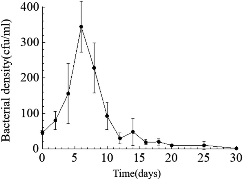
Temporal changes in bacterial density. Throughout the entire static cultivation process, the bacterial density exhibited an overall trend of initially increasing and then decreasing. The initial density of bacteria in the culture medium was 5.3 × 10⁸ cfu mL−1. The HJ-1 strain rapidly proliferated from day 0 to day 6, reaching its maximum bacterial density of 4.2 × 10⁹ cfu mL−1 on the 6th day. Subsequently, the bacterial density began to decline, with a rapid decrease from day 6 to day 14, followed by relatively stable levels from day 14 to day 30. On the 30th day, the bacterial density reached its lowest point at 1.5 × 10⁷ cfu mL−1 (Fig. 2). Throughout the entire experimental process, the bacterial density in the CK group remained at 0.
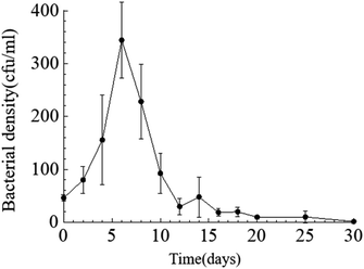 |
| | Fig. 2 Temporal change curve of bacterial density. | |
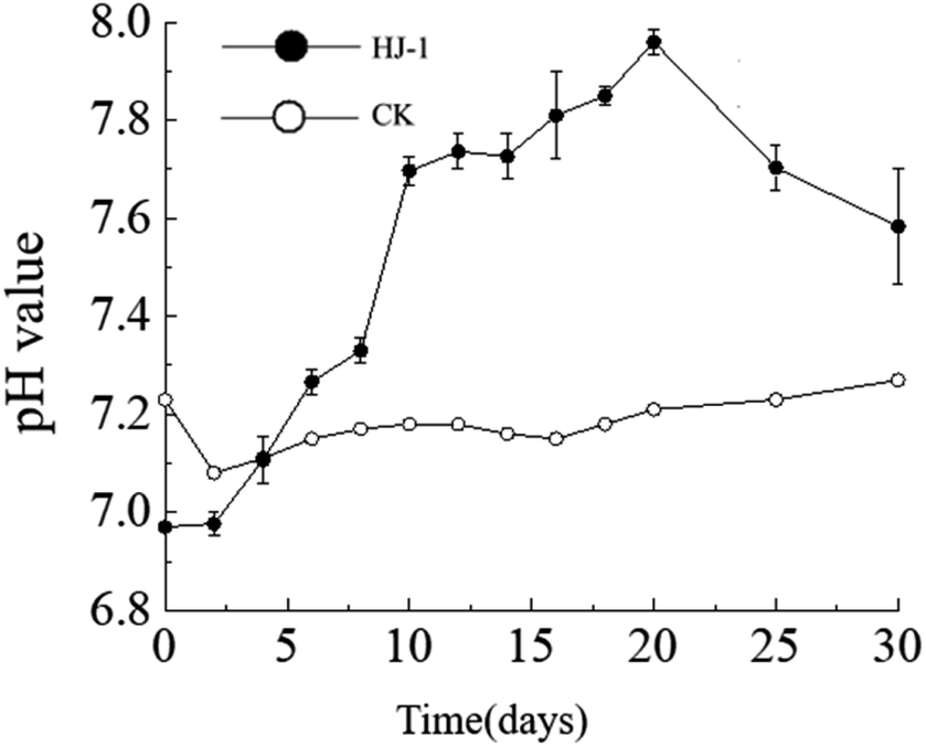
The dynamic changes in pH value. The pH of the culture medium exhibited an overall increasing trend. The pH increased significantly from day 0 to day 10, followed by a slow increase from day 10 to day 20, and a slow decrease from day 20 to day 30. The initial pH of the culture medium was 7.23 (decreasing to 6.97 after the addition of the seed solution), reaching its maximum value of 7.96 on the 20th day of the experiment. In the non-inoculated CK group, the pH of the culture medium remained relatively stable between 7.1 and 7.2 (Fig. 3).
 |
| | Fig. 3 Temporal change curves of pH value. | |
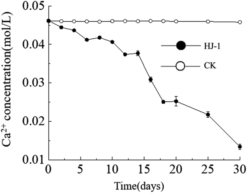
Temporal changes in Ca2+ concentration. Throughout the entire experimental process, the Ca2+ concentration in the culture medium exhibited a consistent decreasing trend, reaching its lowest value of approximately 0.013 mol L−1 on the 30th day. In contrast, the Ca2+ concentration in the CK group remained constant (Fig. 4). The decrease in Ca2+ concentration can be attributed to both the consumption of precipitation reactions and the adsorption of organic matter.
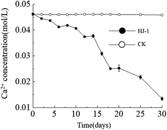 |
| | Fig. 4 Temporal change curves of Ca2+ concentration. | |
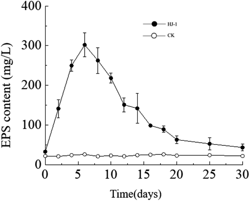
Temporal changes in extracellular polysaccharide content. The extracellular polysaccharide content in the culture medium exhibited a similar trend to the changes in bacterial cell density, with an initial increase followed by a decrease. Specifically, the extracellular polysaccharide content reached its maximum value on the 6th day, approximately 302 mg L−1, and then decreased to near its initial minimum value of approximately 33 mg L−1 on the 30th day (Fig. 5). In the CK group, the extracellular polysaccharide content remained constant at its initial level. In the early stages, bacteria proliferated vigorously and secreted a large amount of extracellular polysaccharides. As time progressed and nutrient resources in the culture medium decreased, the accumulated extracellular polysaccharides in the solution may have been consumed by bacteria as a reserve nutrient, leading to the decrease in extracellular polysaccharide content in the later stages.
 |
| | Fig. 5 Temporal change curves of exopolysaccharides content. | |
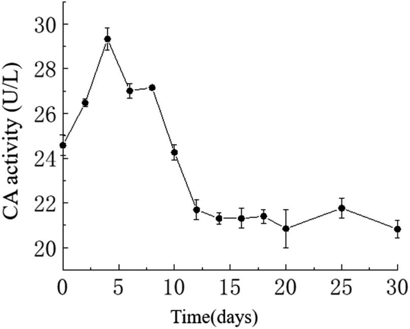
Temporal changes in carbonic anhydrase activity. The activity of carbonic anhydrase (CA) in the culture medium exhibited an overall trend of initially increasing and then decreasing, with a maximum value of approximately 29.33 U L−1 on the 4th day and a minimum value of approximately 20.82 U L−1 on the 30th day. As shown in the graph, in the HJ-1 experimental group, CA activity increased from day 0 to 4 and from day 6 to 8, then decreased from day 4 to 6 and from day 8 to 12, and remained relatively stable from day 12 to 30 (Fig. 6). Throughout the entire experimental process, CA activity in the CK group remained at 0.
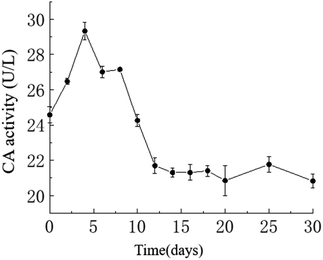 |
| | Fig. 6 Temporal change curve of CA activity. | |
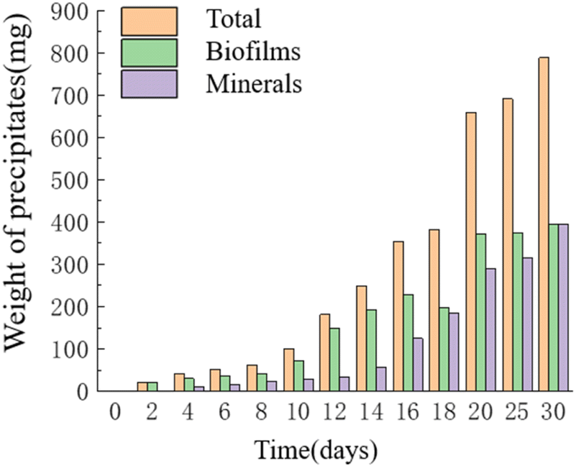
Temporal changes in the weight of precipitates. As time progressed, the mass of precipitates continued to increase, reaching its maximum value of 0.787 g on the 30th day. The HJ-1 strain formed a substantial bacterial biofilm throughout the entire experimental process, serving as a major component of organic constituents in the precipitates, which precipitated alongside minerals. Similarly, the overall mass of organic matter in the culture medium continued to increase, with a slight decrease in organic matter mass on the 16th–18th day and relatively little change in organic matter mass on the 20th–30th day. The mass of minerals in the precipitates continued to increase and reached its maximum value of 0.393 g on the 30th day (Fig. 7). Throughout the entire experimental process, no precipitates were collected from any of the sampling points in the CK group.
 |
| | Fig. 7 Temporal change bar chart of weight of precipitates. | |
Mineralogical and morphological investigation of the precipitated carbonate
Mineral phases of different experimental periods. The XRD spectra of samples in the early stages of the experiment (day 6 and day 10) showed a broad peak in the range of 15°–35°, which is suggestive of characteristic peaks of ACC (Amorphous Calcium Carbonate). Additionally, in the XRD spectrum of the sample on day 10, diffraction peaks corresponding to calcite were also observed, specifically around 29.41° (104) plane, 43.17° (202) plane, and 48.47° (018) plane. In the later stages of the experiment, the XRD spectra of the samples primarily indicated the presence of calcite as the dominant mineral phase. Starting from day 12, more diffraction peaks appeared in the XRD spectra. Comparatively, peaks around 23.11°, 29.53°, 35.79°, 39.64°, 43.13°, 48.35°, and 48.13° (2θ) were identified as corresponding to the (012), (104), (110), (11−3) (202), (018), and (11−6) planes of calcite (Fig. 8).
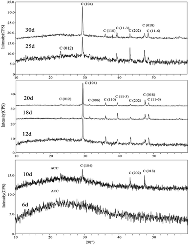 |
| | Fig. 8 XRD patterns of carbonate induced by HJ-1 strain. | |
The FT-IR spectra indicated that the mineral composition in the samples was primarily calcite from day 10 until the end of the experiment. In the spectra from day 10 and day 12, absorption peaks were observed around 870 cm−1, 1400 cm−1, and approximately 711 cm−1, corresponding to the υ2, υ3, and υ4 mode vibrations of calcite (CO32− bending vibration out of plane near 876 cm−1, antisymmetric stretching vibration near 1400 cm−1, and in-plane bending vibration of O–C–O at around 710 cm−1). The percentage of ACC in calcite can be determined by the ratio of the intensities of the υ2 absorption band to the υ4 absorption band (Imaxυ2/Imaxυ4), where the broadening of the υ4 peak sharpens and increases in intensity with increased crystallization.45 A value of Imaxυ2/Imaxυ4 ≤ 3.0 indicates pure calcite, but a value greater than 3.0 suggests an increased ACC content.46–48 Fig. 9 shows the Imaxυ2/Imaxυ4 ratios for four samples as 3.21, 2.62, 2.94, 2.86, and 2.7, respectively. This implies that only a small amount of ACC is present in the early-stage samples throughout the entire experimental process (see in Fig. 9).
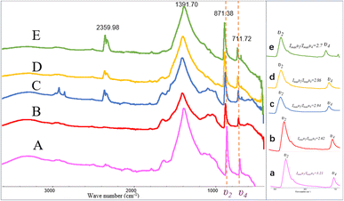 |
| | Fig. 9 FT-IR patterns of carbonate induced by HJ-1 strain. (A–E) FT-IR spectra of samples on days 10, 12, 18, 25, and 30, absorption peaks were observed around 870 cm−1, 1400 cm−1, and approximately 711 cm−1, corresponding to the υ2, υ3, and υ4 mode vibrations of calcite; (a–e) magnified views of the υ2 and υ4 regions in the (A–E) spectra, along with the analysis of Imaxυ2/Imaxυ4 ratios which implies that only a small amount of ACC is present in the early-stage samples throughout the entire experimental process. | |
In addition, in the spectrum of the sample on day 18, in addition to the characteristic peaks of calcite, absorption peaks at 2916 cm−1 and 2849 cm−1 were also observed, corresponding to the stretching vibrations of aliphatic methyl (–CH3) and methylene (–CH2–) groups. Furthermore, in the spectra of the samples on day 18, 25, and 30, an absorption peak around 2359 cm−1 was detected, corresponding to the antisymmetric stretching vibration of CO2 (Fig. 9).
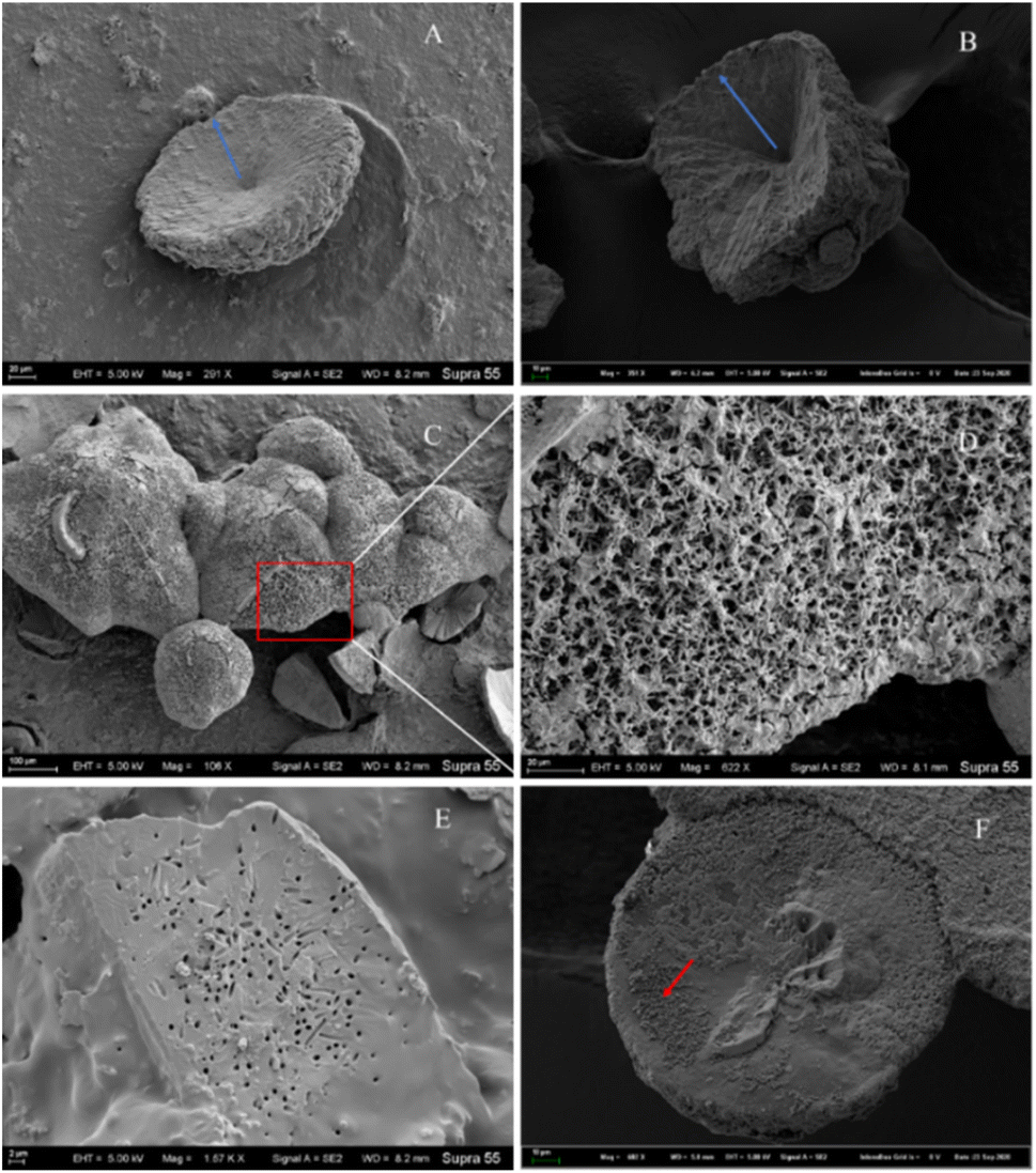
Morphological investigation of the precipitated minerals. During the process of carbonate mineral precipitation induced by the HJ-1 strain, a substantial amount of bacterial biofilm accompanied the precipitation of carbonate minerals (Fig. 7). Upon observation with scanning electron microscopy (SEM), we found that the collected carbonate minerals exhibited predominantly concave-type morphology (Fig. 10A–C). The so-called concave-type minerals refer to a group of carbonate minerals in which, in terms of morphology, the periphery protrudes more than the center, the central part is relatively flat, and there is an outward growth trend. On the backside of these concave carbonate minerals, numerous rod-shaped mineral forms were distributed (Fig. 10D and F). Furthermore, we also observed rod-shaped particles or small pores on some fracture surfaces and hemispheres (Fig. 10E).
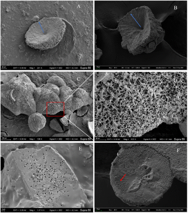 |
| | Fig. 10 Several representative morphologies of carbonate induced by HJ-1 strain. (A) Concave disc-shaped carbonate mineral with a central depression, exhibiting a tendency to grow outward (as indicated by the red arrow), and occasionally small holes with bacterial-like morphology on the surface; (B) concave quadrangular cone-shaped carbonate mineral with a central depression, showing a trend of growth outward (as indicated by the blue arrow); (C and D) the backside of concave-shaped carbonate minerals, featuring numerous particles with bacterial-like morphology on the surface (enlarged view of the red box area in the C and D image); (E) fracture surface of carbonate minerals with visible bacterial-shaped holes; (F) hemispherical carbonate mineral with visible particles resembling bacterial morphology (as indicated by the red arrow). | |
Among all minerals, the predominant form is the concave-type mineral. Most of these minerals have unique shapes, such as disc-shaped, hemispherical, and irregular shapes, among others (Fig. 10). All of the above mineral forms have a common characteristic, which is the presence of particles or small pores resembling bacterial forms on the mineral surface or fracture surface. Throughout the entire experimental process, we consistently found rod-shaped minerals on the surfaces or interiors of different samples. These particles are either scattered individually on the mineral surface or appear clustered on the mineral surface or within (Fig. 10 and 11).
 |
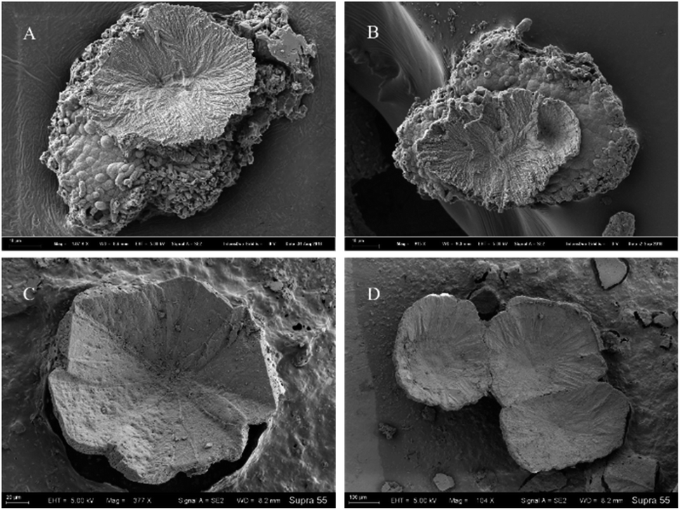
| | Fig. 11 Concave-type morphologies of carbonate minerals templated by bacterial biofilms. (A and B) Represent the morphology of concave-type minerals found in samples from the 10th and 16th days, respectively, with a significant presence of calcified bacteria and biofilms at the bottom. (C and D) Represent the morphology of concave-type minerals observed in samples from the 25th and 30th days, respectively. | |
Microstructural analysis of rod-shaped minerals formed in the mineralization experiment with the HJ-1 strain
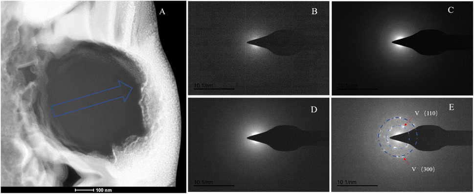
We conducted slice analysis on the rod-shaped minerals using FIB (focused ion beam) technology. We selected three rod-shaped minerals scattered on the surface of the mineral (as indicated by the red arrows in Fig. 10F). The cross-sections revealed that the interior of the rod-shaped minerals was solid (Fig. 12). To further confirm that the selected rod-shaped minerals were calcified bacteria, we performed EDX mapping and SAED analysis on the FIB samples.
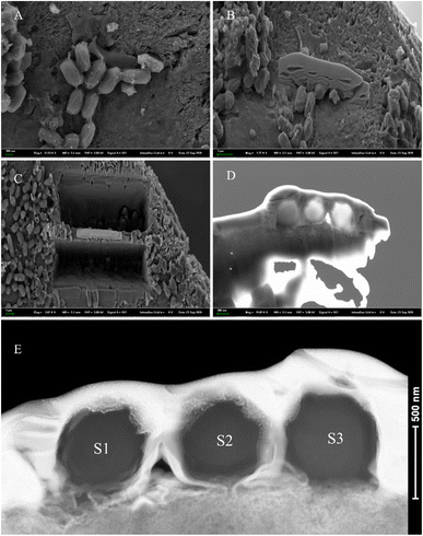 |
| | Fig. 12 SEM images of FIB sectioning process and HAADF-STEM image of the selected calcified bacterial particles. (A) SEM image of the rod-shaped minerals cut by FIB; (B) Pt embedding; (C) process of FIB milling and sample extraction; (D) thin section cut to a thickness of 50–60 nm, containing three rod-shaped mineral particles; (E) HAADF (High-Angle Annular Dark-Field) images, with three sections labeled as S1, S2, and S3. | |
EDX analysis of the sliced section
The EDX mapping results revealed that the elements calcium, carbon, and oxygen were evenly distributed throughout the entire cross-section. Since the selected rod-shaped minerals were not hollow and had unclear boundaries at the cross-section edges, it was not possible to avoid the outer platinum layer when selecting the scanning area. Furthermore, the phosphorus Kα peak and platinum Lα peak overlap, resulting in the signals in image E originating from both phosphorus and platinum elements. However, this clearly indicates that phosphorus/platinum is primarily present at the edge locations. The signals for nitrogen and sulfur elements were weaker, and layering was not prominent (Fig. 13). Note that the elemental distribution maps for cross-sections S1 and S2 were similar to S3. Combining the morphology and spectroscopic analysis, and our previous research about calcified bacteria,49 we can reasonably confirm that the selected rod-shaped mineral particles are calcified bacteria.
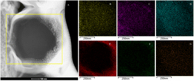 |
| | Fig. 13 EDX mapping of calcified bacterial section of strain HJ-1. (A) HAADF image of the cross-section S3, with EDX mapping performed in the yellow box area; (B–G) elemental distribution maps were generated for calcium, carbon, oxygen, phosphorus/platinum, sulfur, and nitrogen elements. These maps illustrated that calcium, carbon, and oxygen were uniformly distributed across the entire cross-section. Phosphorus/platinum predominantly appeared at the edge locations. Signals for nitrogen and sulfur were weaker, and distinct layering was not prominent. | |
SAED analysis of the sliced section
The SAED analysis of the three sections showed that the mineral composition of the sections primarily consisted of interior ACC and outer marginal vaterite. The diffraction patterns of the sections mainly exhibited characteristics of amorphous materials. Combining elemental analysis, we speculate that the primary mineral component is ACC. The d-values of the diffraction polycrystalline rings at the edges of the S1 section corresponded to the (110) and (300) crystal planes of vaterite (Fig. 14). The d-values of the diffraction polycrystalline rings at the edges of the S2 section corresponded to the (205) crystal plane of vaterite (Fig. 15). The d-values of the diffraction polycrystalline rings at the edges of the S3 section corresponded to the (110) and (205) crystal planes of vaterite (Fig. 16).
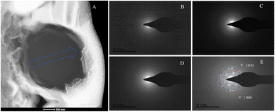 |
| | Fig. 14 SAED analysis of section S1. (A) HAADF image of cross-section S1, with selected area diffraction indicated by the blue arrow. (B–E) Selected area diffraction patterns from the regions indicated by arrows in image (A); among these, (B–D) exhibit characteristics of amorphous materials, and in conjunction with elemental analysis, are presumed to represent ACC; the polycrystalline rings in image (E) correspond to the (100) and (300) crystal planes of vaterite. | |
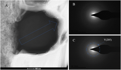 |
| | Fig. 15 SAED analysis of section S2. (A) HAADF image of cross-section S2, with selected area diffraction indicated by the blue arrow; (B and C) selected area diffraction patterns from the regions indicated by arrows in image (A); in (B), amorphous characteristics are observed, and in conjunction with elemental analysis, are presumed to represent ACC; in (C), the polycrystalline ring at the edge of the section corresponds to the (205) crystal plane of vaterite. | |
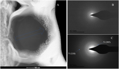 |
| | Fig. 16 SAED analysis of section S3. (A) HAADF image of cross-section S3, with selected area diffraction indicated by the blue arrow; (B and C) selected area diffraction patterns from the regions indicated by arrows in image (A); in (B), amorphous characteristics are observed, and in conjunction with elemental analysis, are presumed to represent ACC; in (C), the polycrystalline rings at the edge of the section correspond to the (110) and (205) crystal planes of vaterite. | |
Discussions
Solution conditions of the precipitation reaction induced by strain HJ-1
In bacterial-induced mineralization, the formation of carbonate minerals is influenced by a multitude of factors, including bacterial density, pH value, extracellular polysaccharide content, and carbonic anhydrase (CA) activity. These factors interplay, significantly impacting the mineralization process. An alkaline environment is crucial for carbonate precipitation, as the combination of metal ions with carbonate ions to form carbonate mineral precipitates primarily occurs under alkaline conditions.4 Across the experimental timeline, the solution's pH value displayed an initial increase followed by a subsequent decrease. During the initial stages, rapid bacterial proliferation and intense metabolic activity significantly influenced the solution's pH value. Bacterial activities such as respiration and organic compound secretion primarily shaped the pH value dynamics. However, as the experiment progressed, bacterial activity diminished, and inorganic reactions in the solution became the main drivers of pH value variation. Hydration of CO2 and calcium carbonate precipitation contributed to lowering the system's pH value. Subsequently, with reduced bacterial activity, the ongoing series of reactions involving CO2 and CaCO3, catalyzed by carbonic anhydrase (CA), predominantly led to the pH decrease.
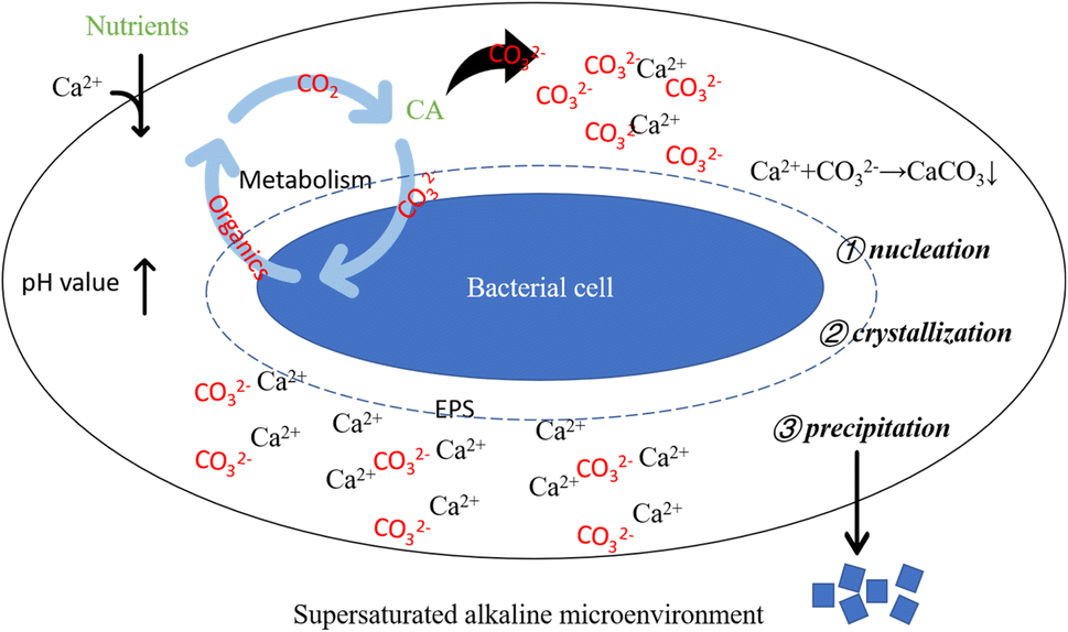
Bacterial metabolic activities stand as pivotal factors driving pH changes in the culture solution. Bacterial proliferation, respiration, programmed cell death, and secreted organic substances can either raise or lower the solution's pH value. Bacteria capable of inducing carbonate precipitation can create a locally supersaturated microenvironment, facilitating the formation and precipitation of carbonate minerals.50 However, pH change alone does not dictate carbonate precipitation. An elevated pH value creates an alkaline milieu for carbonate precipitation, while the presence of CA directly impacts solution saturation. Generally, higher saturation facilitates easier precipitation reactions. CA facilitates CO2 hydration, generating CO32− ions, which subsequently combine with Ca2+ ions in the solution, fostering carbonate mineral formation. Moreover, urease-producing bacteria that hydrolyze urea can contribute CO2 to the system. In bacterial-induced mineralization systems, a cascade of reactions instigated by bacterial life activities establishes a localized alkaline microenvironment, promoting Ca2+ and CO32− ions' supersaturation, thereby initiating nucleation, crystallization, and calcium carbonate formation (as depicted in Fig. 17).
 |
| | Fig. 17 Schematic diagram of alkaline supersaturated microenvironment around bacterial cell. Supersaturated alkaline microenvironment: bacterial life activities result in an elevation of pH, creating a prerequisite for carbonate precipitation; bacteria-secreted CA promotes the hydrolysis of CO2, supplying anions for the precipitation reaction; bacterial cells and their secreted EPS induce crystal nucleation by adsorbing Ca2+. | |
The nucleation mechanism of carbonate minerals induced by HJ-1 strain
According to the FIB-TEM analysis of calcium-precipitating bacteria from the HJ-1 strain, we have determined that the overall composition of the bacterial cross-section consists of CaCO3 (calcium carbonate) and some organic components (see Fig. 13). The predominant mineral composition in the cross-sections of these three calcium-precipitating bacteria is mainly ACC. Furthermore, there is a tendency for ACC at the edges to transform into vaterite (a type of calcium carbonate crystal), indicating a transition from amorphous to crystalline structure from the inner to the outer regions.
In biomineralization and biomimetic mineralization systems, ACC has long been considered a precursor for crystalline carbonate minerals such as vaterite, aragonite, and calcite.51,52 Mann suggested that this preference for amorphous precursors in biomineralization systems is likely because amorphous phases are more readily dissolved compared to crystalline phases under equilibrium conditions.26,53 Under continuous precipitation conditions, the initially formed phase has the highest solubility, and subsequent phases crystallize to reduce the overall solubility. Among the three anhydrous polymorphs of CaCO3, calcite has the lowest solubility, while vaterite has the highest solubility. Therefore, for the CaCO3 series, the crystallization sequence is ACC → vaterite → aragonite → calcite.54
Ostwald–Lussac's phase rule states that in supersaturated solutions, the initially formed phase is typically less stable and will subsequently transform into a thermodynamically more stable phase.55 This is because the nucleation barrier for metastable phases is lower than that for stable phases, making it kinetically favorable for them to form first.56 In the absence of organic polymers in calcium carbonate solution, the amorphous calcium carbonate (ACC) phase can rapidly transform, sometimes initially forming vaterite and then transforming into oriented calcite.50 Bacteria produce negatively charged organic polymers containing carboxylate, sulfate, or phosphate groups as functional groups. Polymers like peptidoglycans and polysaccharides57–59 may induce the formation and/or stabilization of metastable phases.60 These polymers can also induce heterogeneous nucleation by binding to Ca2+ ions and reducing the interfacial energy between crystals and large molecular substrates.59 Bacterial cells, as heterogeneous substrates in biomineralization systems, can reduce the interfacial energy by acting as nucleation sites, leading to the formation of less stable CaCO3 phases. After bacterial calcification, the exposed outer-layer metastable vaterite, due to a less tight association with organic matter, may also undergo partial aging, leading to the detection of calcite on the outer layer. Therefore, the mineral composition from the inside out in bacterial calcification further confirms that ACC is a precursor for bacterially induced carbonate minerals.
Growth mechanism of carbonate polycrystalline induced by HJ-1 strain
In microbial-induced carbonate precipitation systems, morphologies similar to those of chemically precipitated carbonate minerals are often found. This is because various nucleation, crystallization, and crystal growth modes exist in microbial-induced carbonate precipitation systems.61 The vigorous metabolic activities of bacteria can create supersaturated conditions for calcium carbonate nucleation, favoring homogeneous nucleation. Bacterial cells and their secreted organic polymers can adsorb Ca2+ ions from the solution, reducing interfacial energy and promoting heterogeneous nucleation. Furthermore, organic macromolecules can serve as matrices for the aggregation of nanoparticles, leading to the formation of various morphologies of carbonate minerals.56
The mechanism of bio-mineral nanoparticle aggregation proposed by Gebauer et al. suggests that in reaction systems containing large molecular organic polymers, nanometer-sized particles of amorphous precursors tend to aggregate on the surface of large molecules, forming aggregates of nanoparticles templated by the large molecules.62,63 In bacterial-induced mineralization systems, the major large molecular organic substances are the EPS secreted by bacteria, such as extracellular polysaccharides, CA, amino acids, etc. However, in this study, it was found that there was a significant amount of biofilm at the gas–liquid interface, and some of it precipitated together with carbonate minerals (Fig. 7). Bacterial biofilm is composed of approximately 97% extracellular polysaccharides (EPS) and 3% bacterial cells.64,65 EPS serves as a “reserve nutrient” that can provide carbon and nitrogen sources for the later growth and reproduction of bacteria.64,66 Additionally, EPS can adsorb Ca2+ ions from the solution through electrostatic interactions, contributing to the reduction of Ca2+ ion concentration in the solution. As heterogeneous nucleation sites, EPS can promote the nucleation of carbonate minerals and exert some control over crystal growth.57,67,68
In summary, based on this research, the author has constructed a schematic diagram of crystal growth of bacterially induced carbonate minerals, aiming to further elucidate the mineral growth mechanism with bacterial biofilm as a template and calcium-precipitating bacteria and other nanoparticles as structural units. As shown in Fig. 18: step 1: nucleation; step 2: nanoparticle aggregation; step 3: overgrowth. Therefore, the specific morphological evolution pathway is as follows: bacterial biofilm → calcified bacteria clusters (particle aggregation) → concave-type minerals (disc-shaped minerals → sunflower-shaped minerals → concave-type spherical minerals).
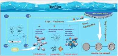 |
| | Fig. 18 Schematic model of the formation mechanism of concave-type minerals. Step 1: nucleation, there are 3 nucleation pathways shown in the model: (A) functional groups exhibiting negative charges on the bacterial cell wall adsorb Ca2+ ions, initiating heterogeneous nucleation as they react with CO32− derived from CO2 hydration. Calcium precipitation follows pathways with lower activation barriers, occurring on the cell surface. (B) Homogeneous nucleation, induced by respiratory by-products, creates locally supersaturated microenvironments, facilitating the nucleation of amorphous nanoparticles. (C) Extracellular polymeric substances (EPS) comprising polysaccharides and proteins act as heterogeneous nucleation sites or templates for nanoparticle aggregation. Step 2: nanoparticle aggregation. Large disc-shaped minerals form within the bacterial biofilm, potentially near gas bubbles transporting carbonate ions. Growing in density, these minerals sink into the solution, with nanoparticles aggregating predominantly on the solution-facing side while maintaining a smooth surface on the bubble-facing side. Step 3: overgrowth. As the minerals sink further into the solution, secondary nucleation occurs at high-energy edges, resulting in overgrowth and the formation of concaved carbonate mineral morphologies. | |
Conclusions
In this study, the Curvibacter lanceolatus HJ-1 strain was selected for bacterial-induced mineralization experiments. We found that bacteria induce the formation of carbonate minerals by creating an alkaline environment conducive to carbonate precipitation, secreting carbonic anhydrase, and providing nucleation sites. Carbonate minerals nucleate on the surface of bacterial cells, and their crystallization sequence follows the Ostwald–Lussac stage law, which includes ACC (amorphous calcium carbonate) → vaterite (→ calcite). Concave-type carbonate minerals may be templated by bacterial biofilms, and calcified bacteria serve as structural units, then undergo three steps of nucleation, nanoparticle aggregation, and edge overgrowth. The specific evolutionary pathway is as follows: bacterial biofilms → calcified bacteria clusters → concave-type minerals (disc-shaped minerals → sunflower-shaped minerals → hemispherical minerals).
Author contributions
Dr Lyu Jiejie and Professor Li Fuchun designed the experimental content of this study and wrote this manuscript. Long Haoran, Zhu Xinru, and Fu Nan assisted in the XRD and SEM analysis of the samples. Guo Ziqi and Zhang Weiqing assisted in the pre-experimental sample preparation. All the individuals mentioned above provided assistance and input in the writing of the paper.
Conflicts of interest
The authors declare that they have no known competing financial interests or personal relationships that could have appeared to influence the work reported in this paper.
Acknowledgements
This work was supported by the National Natural Science Foundation of China [grant No. 42273080 and 41673083], Ministry of Science and Technology of the People's Republic of China, subtopic, STEP2019QZKK0707, the University Natural Science Research Project of Anhui Province (2022AH051317), and the Doctoral Foundation of Fuyang Normal University [grant no. 2021KYQD0014].
Notes and references
- H. L. Ehrlich, Earth-Sci. Rev., 1998, 45(1–2), 45–60 CrossRef CAS.
- L. Addadi, S. Raz and S. Weiner, Adv. Mater., 2003, 15, 959–970 CrossRef CAS.
- T. O. Okyay and D. F. Rodrigues, FEMS Microbiol. Ecol., 2015, 91(3), fiv017 CrossRef PubMed.
- S. Sundaram and I. S. Thakur, Bioresour. Technol., 2018, 253, 368–371 CrossRef CAS PubMed.
- A. Bandyopadhyay, A. Saha, D. Ghosh, B. Dam, A. K. Samanta and S. Dutta, Beni-Suef Univ. J. Basic Appl. Sci., 2023, 12, 1–13 CrossRef.
- Z. Yang, X. Cheng and M. Li, in Geo-Frontiers 2011: Advances in Geotechnical Engineering, 2011, pp. 4031–4040 Search PubMed.
- M. O. Cuthbert, L. A. McMillan, S. Handley-Sidhu, M. S. Riley, D. J. Tobler and V. R. Phoenix, Environ. Sci. Technol., 2013, 47, 13637–13643 CrossRef CAS PubMed.
- V. Achal, A. Mukerjee and M. S. Reddy, Constr. Build. Mater., 2013, 48, 1–5 CrossRef.
- K. Van Tittelboom, N. De Belie, W. De Muynck and W. Verstraete, Cem. Concr. Res., 2010, 40, 157–166 CrossRef CAS.
- A. Ali, M. Li, J. Su, Y. Li, Z. Wang, Y. Bai, E. F. Ali and S. M. Shaheen, Sci. Total Environ., 2022, 813, 152668 CrossRef CAS PubMed.
- Y. Liu, A. Ali, J.-F. Su, K. Li, R.-Z. Hu and Z. Wang, Sci. Total Environ., 2023, 860, 160439 CrossRef CAS PubMed.
- J. T. DeJong, M. B. Fritzges and K. Nüsslein, J. Geotech. Geoenviron. Eng., 2006, 132, 1381–1392 CrossRef CAS.
- H. Canakci, W. Sidik and I. H. Kilic, Soils Found., 2015, 55, 1211–1221 CrossRef.
- C. Jenewein, C. Ruiz-Agudo, S. Wasman, L. Gower and H. Cölfen, CrystEngComm, 2019, 21(14), 2273–2280 RSC.
- D. S. McKay, E. K. Gibson, K. L. Thomas-Keprta, H. Vali, C. S. Romanek, S. J. Clemett, X. D. Chillier, C. R. Maechling and R. N. Zare, Science, 1996, 273, 924–930 CrossRef CAS PubMed.
- R. V. Morris, S. W. Ruff, R. Gellert, D. W. Ming, R. E. Arvidson, B. C. Clark, D. Golden, K. Siebach, G. Klingelhöfer and C. Schröder, Science, 2010, 329, 421–424 CrossRef CAS PubMed.
- G. Aloisi, A. Gloter, M. Krüger, K. Wallmann, F. Guyot and P. Zuddas, Geology, 2006, 34(12), 1017–1020 CrossRef CAS.
- I. A. Bundeleva, L. S. Shirokova, P. Bénézeth, O. S. Pokrovsky, E. I. Kompantseva and S. Balor, Chem. Geol., 2012, 291, 116–131 CrossRef CAS.
- S. Wei, H. Cui, Z. Jiang, H. Liu, H. He and N. Fang, Braz. J. Microbiol., 2015, 46, 455–464 CrossRef PubMed.
- D. Zhuang, H. Yan, M. E. Tucker, H. Zhao, Z. Han, Y. Zhao, B. Sun, D. Li, J. Pan and Y. Zhao, Chem. Geol., 2018, 500, 64–87 CrossRef CAS.
- P. Simon, W. Pompe, D. Gruner, E. Sturm, K. Ostermann, S. Matys, M. Vogel and G. Rödel, ACS Biomater. Sci. Eng., 2022, 8, 526–539 CrossRef CAS PubMed.
- K. Benzerara, N. Menguy, P. López-García, T.-H. Yoon, J. Kazmierczak, T. Tyliszczak, F. Guyot and G. E. Brown, Proc. Natl. Acad. Sci. U. S. A., 2006, 103, 9440–9445 CrossRef CAS PubMed.
- M. Obst, B. Wehrli and M. Dittrich, Geobiology, 2009, 7, 324–347 CrossRef CAS PubMed.
- H. A. Lowenstam, Science, 1981, 211, 1126–1131 CrossRef CAS PubMed.
- Q. Xu, C. Zhang, F. Li, F. Ma, W. Guo, X. Li, L. Li and L. Liu, Geomicrobiol. J., 2017, 34, 157–165 CrossRef CAS.
- S. Mann, Nature, 1988, 332, 119 CrossRef CAS.
- A. Picard, A. Gartman, D. R. Clarke and P. R. Girguis, Geochim. Cosmochim. Acta, 2018, 220, 367–384 CrossRef CAS.
- W. Zhang, Y. Ju, Y. Zong, H. Qi and K. Zhao, Environ. Sci. Technol., 2018, 52, 9266–9276 CrossRef CAS PubMed.
- M. Obst, J. Dynes, J. Lawrence, G. Swerhone, K. Benzerara, C. Karunakaran, K. Kaznatcheev, T. Tyliszczak and A. Hitchcock, Geochim. Cosmochim. Acta, 2009, 73, 4180–4198 CrossRef CAS.
- M. Dittrich and S. Sibler, Geol. Soc. London, Spec. Publ., 2010, 336, 51–63 CrossRef CAS.
- L. B. Gower, Chem. Rev., 2008, 108, 4551–4627 CrossRef CAS PubMed.
- J. De Yoreo, Nat. Mater., 2013, 12, 284–285 CrossRef CAS PubMed.
- S. Schultze-Lam, D. Fortin, B. Davis and T. Beveridge, Chem. Geol., 1996, 132, 171–181 CrossRef CAS.
- D. A. Bazylinski and R. B. Frankel, Environ. Microbe-Met. Interact., 2000, 109–144 CAS.
- L. Chen, Y. Shen, A. Xie, B. Huang, R. Jia, R. Guo and W. Tang, Cryst. Growth Des., 2008, 9, 743–754 CrossRef.
- J. Tourney and B. T. Ngwenya, Chem. Geol., 2009, 262, 138–146 CrossRef CAS.
- I. A. Bundeleva, L. S. Shirokova, P. Benezeth, O. S. Pokrovsky, E. I. Kompantseva and S. Balor, J. Colloid Interface Sci., 2011, 360, 100–109 CrossRef CAS PubMed.
- Y. Xu, K. C. H. Tijssen, P. H. H. Bomans, A. Akiva, H. Friedrich, A. P. M. Kentgens and N. Sommerdijk, Nat. Commun., 2018, 9, 2582 CrossRef PubMed.
- C. Cao, J. Jiang, H. Sun, Y. Huang, F. Tao and B. Lian, Front. Microb., 2016, 7, 366 Search PubMed.
- Z. Liu, Y. Zhang, K. Fa, H. Zhao, S. Qin, R. Yan and B. Wu, Catena, 2018, 170, 64–72 CrossRef CAS.
- C. Zhang, F. Li and J. Lv, J. Cryst. Growth, 2017, 478, 96–101 CrossRef CAS.
- C. Zhang, X. Li, J. Lyu and F. Li, J. Struct. Biol., 2020, 212, 107609 CrossRef CAS PubMed.
- S. Felz, P. Vermeulen, M. C. van Loosdrecht and Y. M. Lin, Water Res., 2019, 157, 201–208 CrossRef CAS PubMed.
- W. S. Chen, Master's thesis, Huazhong University of Science and Technology, 2011 Search PubMed.
- Y. Politi, T. Arad, E. Klein, S. Weiner and L. Addadi, Science, 2004, 306, 1161–1164 CrossRef CAS PubMed.
- E. Beniash, J. Aizenberg, L. Addadi and S. Weiner, Proc. R. Soc. London, Ser. B, 1997, 264, 461–465 CAS.
- E. Loste, R. J. Park, J. Warren and F. C. Meldrum, Adv. Funct. Mater., 2004, 14, 1211–1220 CrossRef CAS.
- A. Jayaraman, G. Subramanyam, S. Sindhu, P. K. Ajikumar and S. Valiyaveettil, Cryst. Growth Des., 2007, 7, 142–146 CrossRef CAS.
- J. Lyu, F. Li, C. Zhang, L. Gower, S. Wasman, J. Sun, G. Yang, J. Chen, L. Gu and X. J. C. G. Tang, Chem. Geol., 2020, 559, 119974 CrossRef.
- E. M. Pouget, P. H. Bomans, J. A. Goos, P. M. Frederik and N. A. Sommerdijk, Science, 2009, 323, 1455–1458 CrossRef CAS PubMed.
- M. A. Rivadeneyra, A. Martin-Algarra, M. Sanchez-Roman, A. Sanchez-Navas and J. D. Martin-Ramos, ISME J., 2010, 4, 922–932 CrossRef CAS PubMed.
- P. J. M. Smeets, A. R. Finney, W. Habraken, F. Nudelman, H. Friedrich, J. Laven, J. J. De Yoreo, P. M. Rodger and N. Sommerdijk, Proc. Natl. Acad. Sci. U. S. A., 2017, 114, E7882–E7890 CrossRef CAS PubMed.
- N. Saxena, M. A. Cremer, E. S. Dolling, H. Nurrohman, S. Habelitz, G. W. Marshall and L. B. Gower, Dent. Mater., 2018, 34, 1378–1390 CrossRef CAS PubMed.
- F. Z. Cui, Q. L. Feng, R. K. Tang, J. M. Ouyang, A. H. Wang and K. Wang, Biomineralization, Tsinghua University Press, Beijing, 2007 Search PubMed.
- J. D. Rimer and M. Tsapatsis, MRS Bull., 2016, 41, 393–398 CrossRef CAS.
- J. J. De Yoreo, P. U. Gilbert, N. A. Sommerdijk, R. L. Penn, S. Whitelam, D. Joester, H. Zhang, J. D. Rimer, A. Navrotsky and J. F. Banfield, Science, 2015, 349, aaa6760 CrossRef PubMed.
- O. Braissant, G. Cailleau, C. Dupraz and E. P. Verrecchia, J. Sediment. Res., 2003, 73, 485–490 CrossRef CAS.
- C. Ercole, P. Cacchio, A. L. Botta, V. Centi and A. Lepidi, Microsc. Microanal., 2007, 13, 42–50 CrossRef CAS PubMed.
- J. L. Arias and M. a. S. Fernández, Chem. Rev., 2008, 108, 4475–4482 CrossRef CAS PubMed.
- M. A. Bewernitz, D. Gebauer, J. Long, H. Cölfen and L. B. Gower, Faraday Discuss., 2012, 159(1), 291–312 RSC.
- W. Guo, H. Ma, F. Li, Z. Jin, J. Li, F. Ma and C. Wang, Geomicrobiol. J., 2013, 30, 749–757 CrossRef CAS.
- D. Gebauer, A. Völkel and H. Cölfen, Science, 2008, 322, 1819–1822 CrossRef CAS PubMed.
- D. Gebauer and H. Cölfen, Nano Today, 2011, 6, 564–584 CrossRef CAS.
- J. W. Costerton, J. Ind. Microbiol., 1995, 15, 137–140 CrossRef CAS PubMed.
- H.-C. Flemming and J. Wingender, Nat. Rev. Microbiol., 2010, 8, 623 CrossRef CAS PubMed.
- A. W. Decho, Ecol. Eng., 2010, 36, 137–144 CrossRef.
- M. Mantilaka, H. Pitawala, R. Rajapakse, D. Karunaratne and K. U. Wijayantha, J. Cryst. Growth, 2014, 392, 52–59 CrossRef CAS.
- J. McCutcheon and G. Southam, Chem. Geol., 2018, 498, 115–127 CrossRef CAS.
|
| This journal is © The Royal Society of Chemistry 2024 |
Click here to see how this site uses Cookies. View our privacy policy here. 
 Open Access Article
 This Open Access Article is licensed under a Creative Commons Attribution-Non Commercial 3.0 Unported Licence
 *b,
Haoran Longa,
Xinru Zhua,
Nan Fua,
Ziqi Guob and
Weiqing Zhangb
*b,
Haoran Longa,
Xinru Zhua,
Nan Fua,
Ziqi Guob and
Weiqing Zhangb