Tuning the organic ligands to optimize the nitrogen reduction performance of Co(II) or Ni(II)-based MOFs†
Ling
Qin
 *ab,
Ying-Xin
Zhao
a,
Qiang
Liu
a,
Jin-Long
An
a,
Han-Xi
Wang
a,
Mao-Feng
Zhang
 a,
Cheng-Wu
Shi
a and
He-Gen
Zheng
 *c
*c
aSchool of Chemistry and Chemical Engineering, Hefei University of Technology, Hefei, 230009, Anhui, P. R. China. E-mail: qinling@hfut.edu.cn
bSchool of Materials Science and Engineering, Hefei University of Technology, Hefei, 230009, Anhui, P. R. China
cState Key Laboratory of Coordination Chemistry, School of Chemistry and Chemical Engineering, Collaborative Innovation Center of Advanced Microstructures, Nanjing University, Nanjing 210023, P. R. China. E-mail: zhenghg@nju.edu.cn
First published on 3rd July 2024
Abstract
The electrocatalytic nitrogen reduction to ammonia reaction (eNRR) can use clean energy and catalyst materials to convert N2 to NH3 under relatively mild conditions, but how to design and synthesize electrocatalysts has been the focus of eNRR research. Metal–organic frameworks (MOFs) are a class of crystalline porous materials with a high specific surface area, high porosity and a designable structure, and show great potential as new electrocatalysts. Designing and synthesizing MOFs with high stability and high conductivity, and optimizing the adsorption energy of MOFs with nitrogen and intermediates are the key to improve the electrocatalytic performance. Hence, five Co-MOFs with a similar structure were designed to investigate the effect of small changes in the organic ligand structure on nitrogen reduction performance. Among them, the Co-MOF based on the thiazole ligand shows the best eNRR performance, with the highest NH3 yield (51.30 μg h−1 mgcat−1) and Faraday efficiency (29.2%) at −0.4 V vs. RHE. This study can provide theoretical guidance for the design and development of high-performance eNRR electrocatalysts in the future.
1. Introduction
Ammonia (NH3) is an indispensable chemical and one of the most important raw materials in modern agriculture and industry, and also has a large hydrogen capacity and high energy density, making it an ideal energy carrier.1 The nitrogen content of the air is almost 80%, which has been the best raw material for industrial NH3 synthesis.2 Currently, the dominant process for NH3 synthesis by nitrogen reduction is the old Haber–Bosch method, and the process requires high temperature and pressure conditions, consumes high energy and involves high risk during the reaction process.3 Therefore, it is necessary to develop a practical method that can perform the nitrogen reduction reaction for NH3 synthesis at ambient temperature and pressure. The electrocatalytic nitrogen reduction reaction (eNRR) offers potential for synthesis of NH3 at ambient temperature and pressure. However, the activation and dissociation of N![[triple bond, length as m-dash]](https://www.rsc.org/images/entities/char_e002.gif) N and the competitive hydrogenolysis reaction (HER) are two major challenges for the eNRR.4
N and the competitive hydrogenolysis reaction (HER) are two major challenges for the eNRR.4
Metal–organic frameworks (MOFs) are a class of ordered structures assembled by metal nodes (or cluster units) and organic ligands via coordination bonds.5–7 They have the advantages of unique porous structure, diversity and adjustability of structure and composition, and have been widely used in gas separation, energy storage, drug transportation, catalysis and other fields.8 The use of highly active primary MOFs as catalysts is beneficial to improve the energy efficiency of the relevant reaction processes.9–12 Considering the uniqueness and diversity of MOF structures, the electrocatalytic activity of the primary MOFs can be improved by engineering such as adjusting the organic ligand and coordination structure and optimizing the electronic structure or constructing defects. Among them, the organic ligands of MOFs are important for electron trapping,13 separation and transport due to their induced and conjugated roles in organic structures. Heteroatoms (O, N, or S) with lone pair electrons are introduced into conjugated rings, thereby changing the electron density, forming an uneven electron density distribution and promoting the separation and transfer of charge.14,15 Chen et al.16 designed and prepared a series of Zr-MOF photocatalysts using organic ligands with different electron density distributions. The ligand containing more N has the highest charge density difference, and has a significant effect on the optical properties of the catalyst. Here, we provide an effective strategy of modulating the microenvironment of the MOF catalysts by controlling the type of ligand to enhance their intrinsic activity.
In this work, five linear pyridine ligands with different functional blocks were designed, dpt, bptz, bpat, dpb and pds (dpt = 2,5-di(pyridin-4-yl)-1,3,4-thiadiazole, bptz = 3,6-bis(4′-pyridyl)-1,2,4,5-tetrazine, bpat = 3,5-bis(pyridine-4-yl)-4-amino-1,2,4-triazole, dpb = 1,4-di(pyridin-4-yl)benzene, and pds = 4,4-bipyridyl disulfide) and self-assembled with cobalt nitrate (Co(NO3)2·6H2O) as well as a co-ligand thiophene dicarboxylic acid (H2tdc = thiophene-2,5-dicarboxylic acid) to obtain five Co-MOFs, that are Co-dpt-H2tdc, Co-bptz-H2tdc, Co-bpat-H2tdc, Co-dpb-H2tdc, and Co-pds-H2tdc (Scheme 1). The effect of different organic ligands on the performance of catalysts for the eNRR was explored. Among them, Co-dpt-H2tdc has the best nitrogen reduction properties and the highest NH3 yield (51.30 μg h−1 mgcat−1) and Faraday efficiency (29.2%) were obtained at −0.4 V vs. RHE. This work provides an effective strategy to improve electrochemical nitrogen reduction performance by modulating organic ligands.
2. Experimental
2.1 Preparation of Co-dpt-H2tdc
0.02 g Co(NO3)2·6H2O, 0.005 g dpt and 0.004 g H2tdc were dissolved in 2.5 mL N,N-dimethylformamide (DMF = N,N-dimethylformamide). To the mixture, 3 mL deionized water was slowly added and sonicated for 10 minutes. The mixed solution is placed in a stainless steel reactor lined with PTFE, after 2880 min at 85 °C, cooled naturally to room temperature. Abundant red and prismatic crystals were obtained, the crystals were filtered, washed twice with DMF, deionized water and ethanol and dried, and the resulting crystal is Co-dpt-H2tdc. The yield based on the dpt ligand was calculated to be 69%. The synthesis conditions and crystal information of five Co-MOFs are presented in Table S1 (ESI†).2.2 Preparation of Co-bptz-H2tdc
Co-bptz-H2tdc was synthesized in a similar way to Co-dpt-H2tdc except that dpt was replaced by bptz, and the ratio of DMF to water is adjusted to 1 mL![[thin space (1/6-em)]](https://www.rsc.org/images/entities/char_2009.gif) :
:![[thin space (1/6-em)]](https://www.rsc.org/images/entities/char_2009.gif) 1 mL. The red and prismatic crystals were obtained. The yield based on the bptz ligand was calculated to be 51%.
1 mL. The red and prismatic crystals were obtained. The yield based on the bptz ligand was calculated to be 51%.
2.3 Preparation of Co-bpat-H2tdc
0.04 g Co(NO3)2·6H2O, 0.01 g bpat and 0.008 g H2tdc were dissolved in 1 mL N,N-dimethylacetamide (DMA = N,N-dimethylacetamide), and to the mixture 1 mL deionized water was slowly added and sonicated for 10 minutes. The subsequent steps are similar to those for Co-dpt-H2tdc. Purplish-red and prismatic crystals were obtained. The yield based on the bpat ligand was calculated to be 66%.2.4 Preparation of Co-dpb-H2tdc
0.02 g Co(NO3)2·6H2O, 0.005 g dpb and 0.01 g H2tdc were dissolved in 1.5 mL DMF, and to the mixture 1 mL deionized water was slowly added and sonicated for 10 minutes. The subsequent steps are similar to those for Co-dpt-H2tdc. Pink and needlelike crystals were obtained. The yield based on the dpb ligand was calculated to be 46%.2.5 Preparation of Co-pds-H2tdc
0.02 g Co(NO3)2·6H2O, 0.01 g pds and 0.008 g H2tdc were dissolved in 2 mL DMF, and 1 mL deionized water was slowly added and sonicated for 10 minutes. The subsequent steps are similar to those for Co-dpt-H2tdc. Pink and block crystals were obtained. The yield based on the pds ligand was calculated to be 63%.3. Results and discussion
3.1 Characterization
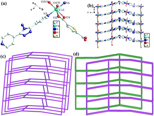
The structural formula of Co-bpat-H2tdc is {[Co(bpat)(tdc)(H2O)·DMA]}n, which belongs to the hexagonal crystal system of the P61 space group. In the least asymmetric unit, there are one Co(II) ion, one tdc2− anion, one bpat ligand, one coordinated H2O and one lattice DMA (Fig. 2a). Co1 was connected by two N atoms from bpat in the axial position, three O atoms from tdc2− ligands and one O atom from water molecule in the plane position. Relying on the coordinate interaction between nitrogen and Co ions, the bpat molecule bridges Co centers into a 61 helix (Fig. S1a, ESI†). The resulting 61 helices with the same handedness are further linked up by the tdc2− ligands to form a chiral 3D framework (Fig. 2b). Attributed to the H-bond interaction between the coordinated H2O and the amino group of bpat as well as the lattice DMA, the DMA molecules form a secondary helical chain inside the molecular helix (Fig. S1b, ESI†). Co1 can be regarded as 4-connected nodes, and bpat and tdc2− ligands can be regarded as linkers. A topology analysis reveals that the structure can be represented as a quartz-dual topology, with the Schläfli symbol {412.63} (Fig. 1c), which is an intrinsically chiral net.18,19 The potential voids are large enough to be filled via mutual interpenetration of an independent equivalent framework, generating a 2-fold interpenetrating architecture.
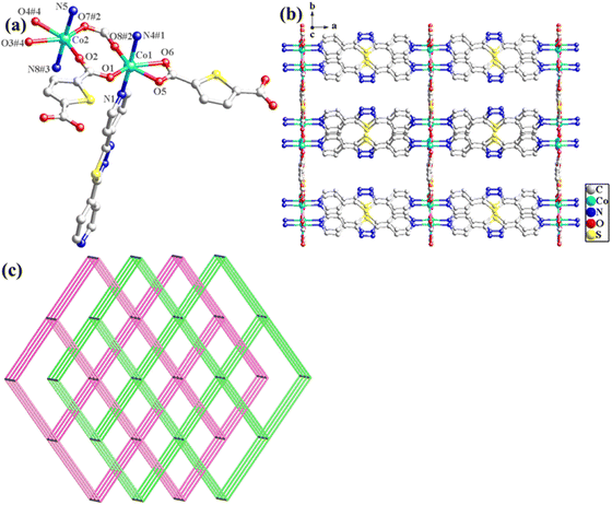
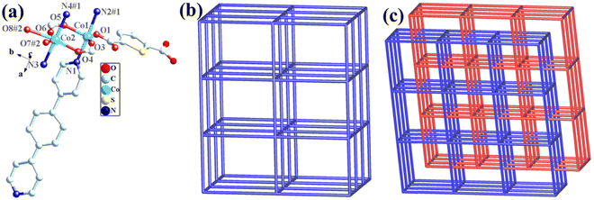
The structural formula of Co-dpb-H2tdc is {Co2(dpb)2(tdc)2}n, which belongs to the monoclinic crystal system of the P21/c space group. Its structure is isomorphic to that of Co-dpt-H2tdc. In the least asymmetric unit, there are two Co(II) ions, two tdc2− anions and two dpb ligands (Fig. 3a). Co1 was five-coordinated and connected by two N atoms from dpb in the axial position, and three O atoms from tdc2− ligands in the plane position. Co2 was six-coordinated by two N atoms from dpb in the axial position, and four O atoms from tdc2− ligands in the plane position. Co1 and Co2 were linked by two carboxyl groups to form a binuclear cluster unit, which was connected by dpb and tdc2− ligands to generate a three-dimensional structure. The binuclear cluster unit can be regarded as 4-connected nodes, and the dpb and tdc2− ligands can be regarded as linkers. A topology analysis reveals that the structure can be represented as a pcu topology, with the Schläfli symbol {412·63} (Fig. 3b). The potential voids are large enough to be filled via mutual interpenetration of an independent equivalent framework, generating a 2-fold interpenetrating architecture (Fig. 3c).
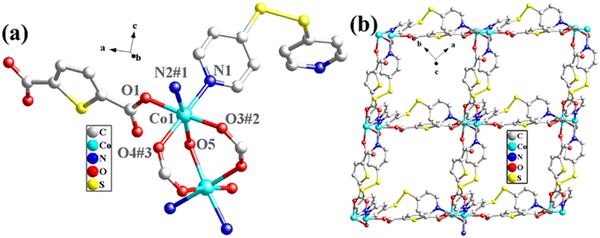
The structural formula of Co-pds-H2tdc is {Co2(pds)2(tdc)2(H2O)}n, which belongs to the orthorhombic crystal system of the C2221 space group. The least asymmetric unit contains two Co(II) ions, two pds ligands, two tdc2− ligands, and one coordinated water molecule (Fig. 4a). Co1 and Co2 were linked by two carboxyl groups and one water molecule to form a binuclear cluster unit, which was connected by pds and tdc2− ligands to generate a two-dimensional structure (Fig. 4b).
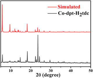 | ||
| Fig. 5 PXRD pattern of synthesized Co-dpt-H2tdc and standard spectra simulated using single crystal data. | ||
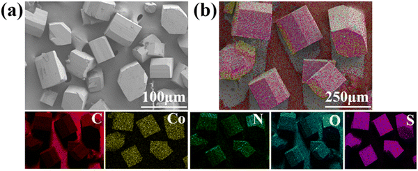
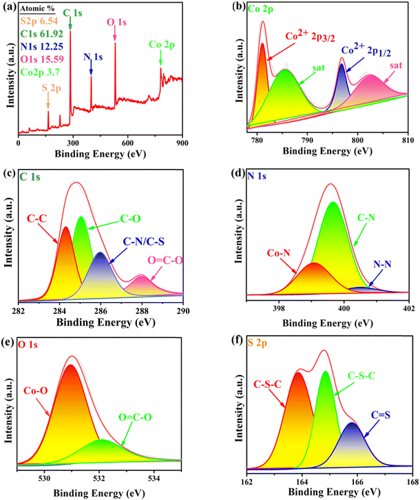
![[double bond, length as m-dash]](https://www.rsc.org/images/entities/char_e001.gif) C–O. In the N 1s XPS spectrum (Fig. 7d), the peaks located at 399.4, 399.9 and 401.4 eV can be attributed to Co–N, C–N and N–N.21,22 In the O 1s spectrum of the sample (Fig. 7e), the peaks observed at 530.98 and 532.08 eV can be attributed to Co–O and O
C–O. In the N 1s XPS spectrum (Fig. 7d), the peaks located at 399.4, 399.9 and 401.4 eV can be attributed to Co–N, C–N and N–N.21,22 In the O 1s spectrum of the sample (Fig. 7e), the peaks observed at 530.98 and 532.08 eV can be attributed to Co–O and O![[double bond, length as m-dash]](https://www.rsc.org/images/entities/char_e001.gif) C–O, respectively.21,23 In the S 2p XPS spectrum (Fig. 7f), two peaks located at 163.86 and 164.84 eV can be attributed to C–S–C, the peak at 165.80 eV can be attributed to C
C–O, respectively.21,23 In the S 2p XPS spectrum (Fig. 7f), two peaks located at 163.86 and 164.84 eV can be attributed to C–S–C, the peak at 165.80 eV can be attributed to C![[double bond, length as m-dash]](https://www.rsc.org/images/entities/char_e001.gif) S, and there were more C
S, and there were more C![[double bond, length as m-dash]](https://www.rsc.org/images/entities/char_e001.gif) S bonds in Co-dpt-H2tdc compared to those in the other S 2p spectra. The new peaks at 401.4 eV in the N 1s XPS spectrum for Co-bpat-H2tdc (Fig. S4c, ESI†) compared to that in Co-dpt-H2tdc are attributed to the amino group. In addition, since the dpb and pds ligands of Co-dpb-H2tdc and Co-pds-H2tdc do not contain N–N, there were no N–N peaks in the N 1s XPS spectra (Fig. S5c and S6c, ESI†). In addition, since there is S–S in the pds ligand in Co-pds-H2tdc (Fig. S6f, ESI†), in the S 2p XPS spectrum there is a S–S peak at 163.87 eV, instead of C
S bonds in Co-dpt-H2tdc compared to those in the other S 2p spectra. The new peaks at 401.4 eV in the N 1s XPS spectrum for Co-bpat-H2tdc (Fig. S4c, ESI†) compared to that in Co-dpt-H2tdc are attributed to the amino group. In addition, since the dpb and pds ligands of Co-dpb-H2tdc and Co-pds-H2tdc do not contain N–N, there were no N–N peaks in the N 1s XPS spectra (Fig. S5c and S6c, ESI†). In addition, since there is S–S in the pds ligand in Co-pds-H2tdc (Fig. S6f, ESI†), in the S 2p XPS spectrum there is a S–S peak at 163.87 eV, instead of C![[double bond, length as m-dash]](https://www.rsc.org/images/entities/char_e001.gif) S in Co-dpt-H2tdc. The bonding information from the XPS spectra is consistent with that obtained from single crystal diffraction data (Fig. S3–S6, ESI†).
S in Co-dpt-H2tdc. The bonding information from the XPS spectra is consistent with that obtained from single crystal diffraction data (Fig. S3–S6, ESI†).
3.2 Electrochemical NRR performance
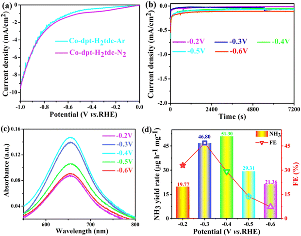
To evaluate the ambient eNRR performance, catalysts were coated on a carbon cloth (CC) (2 cm × 1 cm) and tested in 0.1 M Na2SO4 solution under ambient conditions using a H-type electrolytic cell (Nafion 115 membrane for isolation). The carbon cloth supported by the catalyst is fixed in the cathode chamber through the platinum plate electrode clamp. The generated NH3 was quantified by the indophenol blue method and Nessler's reagent spectrophotometry, and the content of the by-product hydrazine hydrate (N2H4) was also tested using the Watt–Chrisp method to exclude interference from by-products. Fig. S7–S9 (ESI†) show the standard curves for the determination of NH3 and N2H4.The linear sweep voltammetry (LSV) curves of five Co-MOFs in Ar and N2 saturated 0.1 M Na2SO4 electrolytes (Fig. 8a and Fig. S10a–S13a, ESI†) were obtained to evaluate the eNRR activity. For these Co-MOFs, the current densities in N2 were higher than that in Ar at different potentials from −0.2 V to −0.7 V, the difference in current density is due to the consumption of electrons during the eNRR process, indicating that all five Co-MOFs show eNRR activity. In addition, the eNRR performance of five Co-MOFs was evaluated by means of the i–t method at different voltages, the i–t curve of Co-dpt-H2tdc (Fig. 8b) shows that the current density remains stable from −0.2 V to −0.6 V, the NH3 yield was calculated using the indophenol blue method and the UV-visible spectra at the corresponding voltage are shown in Fig. 8c. As shown in Fig. 8d, the NH3 yield as well as Faraday efficiency (FE) of Co-dpt-H2tdc showed a volcano-like trend, with the best NH3 yield (51.30 μg h−1 mgcat−1) and FE (29.2%) at −0.4 V. The i–t tests were performed on Co-bptz-H2tdc at different potentials from −0.3 V to −0.7 V (Fig. S10b, ESI†), and the highest NH3 yield (40.98 μg h−1 mgcat−1) and FE (67.4%) were obtained at −0.3 V (Fig. S10c and d, ESI†); the i–t test was performed at different potentials from −0.3 V to −0.7 V for Co-bpat-H2tdc (Fig. S11b, ESI†), and the highest NH3 yield (35.93 μg h−1 mgcat−1) and FE (17.4%) were obtained at −0.5 V (Fig. S11c and d, ESI†); the i–t test was performed at different potentials from −0.3 V to −0.7 V for Co-dpb-H2tdc (Fig. S12b, ESI†), and the highest NH3 yield (22.86 μg h−1 mgcat−1) and FE (25.9%) were achieved at −0.3 V (Fig. S12c and d, ESI†); the i–t test was performed at different potentials from −0.2 V to −0.6 V for Co-pds-H2tdc (Fig. S13b, ESI†), and the highest NH3 yield (19.75 μg h−1 mgcat−1) and FE (12.2%) were achieved at −0.3 V (Fig. S13c and d, ESI†). By comparing the NH3 yields of the five Co-MOFs, the yields follow the following order: Co-dpt-H2tdc > Co-bptz-H2tdc > Co-bpat-H2tdc > Co-dpb-H2tdc > Co-pds-H2tdc (Fig. S14, ESI†).
In order to elucidate the better eNRR activity of Co-dpt-H2tdc compared to the other four catalysts, electrochemically active surface area (ECSA) tests were carried out to analyze the effect of active sites on the eNRR.24,25 Firstly, in the non-Faraday interval, the CV curves were measured at different scan rates for the five catalysts to obtain their double layer capacitance (Cdl) (Fig. S15, ESI†), the Cdl values of the five catalysts, Co-dpt-H2tdc, Co-bptz-H2tdc, Co-bpat-H2tdc, Co-dpb-H2tdc and Co-pds-H2tdc, were 3.2193 mF cm−2, 1.41075 mF cm−2, 1.04568 mF cm−2, 0.814 mF cm−2, and 0.45343 mF cm−2, respectively. The ECSA values for each catalyst were then determined according to the relationship ECSA = Cdl/Cs.26 Co-dpt-H2tdc has the largest electrochemical surface area, as shown in Fig. S15g (ESI†), the ECSA value of Co-dpt-H2tdc was almost 7 times higher than that of Co-pds-H2tdc, and the results suggest that Co-dpt-H2tdc may provide more active sites for the eNRR reaction. Secondly, the charge transfer capacity of the five catalysts was also measured by electrochemical impedance spectroscopy (EIS) and Fig. S16 (ESI†) shows the EIS of the five catalysts. As shown in the Nyquist diagram, Co-dpt-H2tdc has the lowest charge transfer resistance (Rct) among the five catalysts, suggesting that Co-dpt-H2tdc has the strongest electron–hole pair separation and charge transfer capacity. For Co-pds-H2tdc, the non-conjugation pds ligand caused a poor conductivity compared to the other four catalysts. The introduction of heteroatoms N and S with lone pairs of electrons into conjugated ligands can modulate the charge transfer capacity of the organic ligand. Both the ECSA and EIS results are consistent with the eNRR results, which indicates that regulating the microenvironments of the catalysts by changing the ligand type and increasing the intrinsic activity of Co-MOFs is an effective strategy.
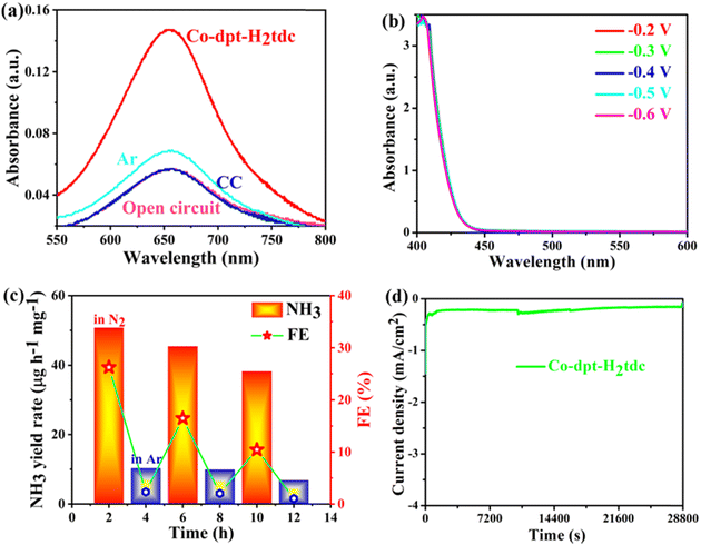
In order to exclude possible interference by pollutants, a series of controlled experiments were carried out (Fig. 9a). eNRR experiments on Co-dpt-H2tdc were carried out at the open-circuit potentials with nitrogen as the feed gas, and the intensity of the UV-visible absorption peaks was comparable to that of the blank electrolyte, indicating that no NH3 was produced at open-circuit potentials. Similar results were obtained when the bare carbon cloth was tested at −0.4 V with N2 as a feed gas. In addition, when we change N2 into Ar as a feed gas, the UV-visible absorption peak intensity is slightly higher than that of the blank electrolyte, but the intensity is much lower than that of Co-dpt-H2tdc at −0.4 V with nitrogen as the feed gas, so the NH3 yield under Ar conditions is negligible. The above results suggest that the observed NH3 is mainly produced through the eNRR. The complex reaction pathway of the eNRR raises concerns about the possible formation of the byproduct N2H4, the electrolyte was tested at different voltages of Co-dpt-H2tdc and no absorbance was detected at 455 nm (Fig. 9b), indicating that byproduct N2H4 production during the eNRR is excluded, and it can be inferred that Co-dpt-H2tdc exhibits excellent selectivity for the eNRR.
A long-term cycling test was further performed to investigate the stability property of the Co-dpt-H2tdc electrocatalyst. The alternating cycling test of the electrocatalytic eNRR was performed at −0.4 V using N2 and Ar saturated 0.1 M Na2SO4 (Fig. 9c). The NH3 yield rate and Faradaic efficiency of the Co-dpt-H2tdc catalyst can be maintained in each cycle in a N2-saturated electrolyte, while very low activity is observed in an Ar-saturated electrolyte, which indicates that NH3 production was generated via N2 electrochemical reduction.27 More importantly, Co-dpt-H2tdc exhibited great robustness and durability for a continuous 8 h long electrochemical NRR, with almost no decease of the NH3 yield rate and FE (Fig. 9d). In addition, the structural integrity of Co-dpt-H2tdc electrocatalysts after 2 h of eNRR testing was verified using PXRD patterns (Fig. S17, ESI†), which showed that the XRD pattern of Co-dpt-H2tdc did not change after eNRR testing compared to the XRD spectra simulated from the single crystal data as well as the XRD pattern of Co-dpt-H2tdc prior to eNRR testing.
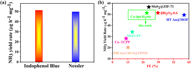
We tested the ammonia yield rate of Co-dpt-H2tdc at −0.4 V by Nessler's reagent spectrophotometry, and the NH3 yield rate at −0.4 V determined by Nessler's reagent spectrophotometry approximates the results detected by the indophenol blue method (Fig. 10a). These results confirm the accuracy of our method for detecting ammonia yield. Furthermore, it is noteworthy that Co-dpt-H2tdc exhibits very superior performance compared to other eNRR electrocatalysts (Fig. 10b and Table S4, ESI†).28–33
According to the above eNRR test results, the five Co-MOFs have different eNRR properties (Fig. 11), which confirmed that tuning the organic ligands can optimize the nitrogen reduction to ammonia performance of Co-MOFs.
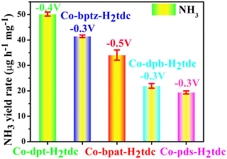 | ||
| Fig. 11 NH3 yield rate of five Co-MOF-based electrocatalysts based on similar ligands at their respective maximum potential. | ||
To verify the above results, we synthesized five Ni-MOFs using the same ligand and the same method, namely, Ni-dpt-H2tdc, Ni-bptz-H2tdc, Ni-bpat-H2tdc, Ni-dpb-H2tdc, and Ni-pds-H2tdc, and the standard powder diffraction spectra simulated from the single-crystal diffraction data matched well with the XRD spectra of the five Ni-MOFs (Fig. S18, ESI†), which confirmed the successful synthesis of the samples. The results of eNRR tests show that the sequence of the five Ni-MOFs is consistent with that of the Co-MOFs (Fig. S19, ESI†). The results show that it is an effective strategy to improve the performance of electrocatalytic NRR by regulating organic ligands. The nitrogen fixation properties of the five synthesized Co-MOFs are better than those of Ni-MOFs. The results may be attributed to: Co2+ and Ni2+ with the same coordination configuration, the configurations of Co2+ and Ni2+ electrons in the orbitals are different, and the electronegativity of Co2+ is slightly lower than that of Ni2+. Fewer valence electrons in the d orbital and smaller electronegativity may be more likely to catalyze nitrogen reduction to ammonia synthesis.34–36
Five Co-MOFs with a similar composition and structure have different eNRR properties, mainly due to the following reasons: (1) Co-pds-H2tdc based on the pds ligand (Fig. S20, ESI†) has a poor electrical conductivity due to the non-conjugation of the pds ligand, therefore, Co-pds-H2tdc has the worst nitrogen reduction performance of ammonia synthesis among the five Co-MOFs, which can be verified by the impedance results. (2) The other four ligands are all conjugated ligands, so the nitrogen reduction performance of the four Co-MOFs is better, in which the dpb ligand has a uniform distribution of electrons on the benzene ring, while bpat, bptz and dpt have a higher electron density on the heterocyclic ring. (3) When different heteroatoms are introduced into the organic ligand, the electronegativity difference between the elements regulates the charge density difference of the organic ligand,16,37 which can enhance the internal electric field and ultimately improve the performance of nitrogen reduction to synthesise ammonia. (4) In addition, the introduction of nitrogen and sulfur atoms in the bpat, bptz and dpt ligands can improve the electrical conductivity and regulate the adsorption capacity of the active sites. Heterogeneous atom doping is a feasible choice to increase the number of active sites, optimize the kinetic process, and regulate the electronic structure and adsorption free energy of the electrocatalyst, which was also confirmed by the results of the active specific surface area.38,39 (5) As an important nonmetallic element in nitrogen enzymes, sulfur plays a crucial role in the biological reduction of N2.40,41 Many studies have shown that the introduction of sulfur atoms into a catalyst can promote the adsorption of N2, and may change the charge distribution of metals and promote the hydrogenation of N2 to NH3.42,43 (6) By designing organic ligands with a similar structure and different functional blocks and constructing Co-MOFs with different pore environments, the pore structure can be adjusted to improve nitrogen adsorption and activation and ammonia desorption and increase ammonia yield. It can also balance the affinity and hydrophobicity of nitrogen, inhibit the hydrogen evolution reaction, and improve the Faraday efficiency.44–46
4. Conclusion
To summarize, five Co-MOFs with a similar structure for achieving enhanced nitrogen reduction reaction were developed. Owing to the enhanced electron transfer and increased electrochemical surface area, the Co-dpt-H2tdc electrocatalyst exhibits the desirable catalytic activity for NH3 production with a yield rate of 51.30 μg h−1 mgcat−1 and a Faraday efficiency of 29.2%, which is significantly higher than those of other four Co-MOFs. This work provides insights into the field of optimizing ligands to improve the performance of nitrogen reduction electrocatalysts.Author contributions
Ling Qin: methodology, conceptualization, supervision, writing – review and editing, project administration, and funding acquisition. Ying-Xin Zhao: writing – original draft, methodology, conceptualization, formal analysis, data curation, and validation. Qiang Liu: validation and data curation. Jin-Long An: validation and data curation. Han-Xi Wang: validation and data curation. Mao-Feng Zhang: supervision. Cheng-Wu Shi: supervision. He-Gen Zheng: supervision.Data availability
Crystallographic data for four Co-MOFs have been deposited at the CCDC under 2350963, 2350964, 2269367 and 2269368.Conflicts of interest
There are no conflicts to declare.Acknowledgements
This work was supported by grants from the National Natural Science Foundation of China (21601045, 62275072) and Anhui Provincial Key Research and Development Plan (2022i01020024).References
- H. A. Alhadidi Almheiri, N. Singh, D. Shetty, K. Polychronopoulou and A. A. Alhammadi, A Mo-salicylaldehyde-linker (Mo-Tp) based 2D MOF as a single-atom catalyst for the nitrogen reduction reaction, J. Mater. Chem. A, 2024, 12, 7058–7066 RSC.
- X. Y. Chen, Y. R. Wang and X. C. Meng, Fabrication of NiSx/MoS2 interface for accelerated charge transfer with greatly improved electrocatalytic activity in nitrogen reduction to produce ammonia, Chem. Eng. J., 2024, 479, 147701 CrossRef CAS.
- A. U. Shetty and R. Sankannavar, Exploring nitrogen reduction reaction mechanisms in electrocatalytic ammonia synthesis: A comprehensive review, J. Energy Chem., 2024, 92, 681–697 CrossRef CAS.
- H. M. He, H. K. Li, Q. Q. Zhu, C. P. Li, Z. Zhang and M. Du, Hydrophobicity modulation on a ferriporphyrin-based metal-organic framework for enhanced ambient electrocatalytic nitrogen fixation, Appl. Catal., B, 2022, 316, 121673 CrossRef CAS.
- G. L. Gao, X. L. Chen, L. Han, G. Zhu, J. Jia, A. Cabot and Z. X. Sun, Advances in MOFs and their derivatives for non-noble metal electrocatalysts in water splitting, Coord. Chem. Rev., 2024, 503, 215639 CrossRef CAS.
- B. Han, L. X. Zhong, C. L. Chen, J. Ding, C. Lee, J. W. Liu, M. X. Chen, S. Tso, Y. Hu, C. D. Lv, Y. Han, B. Liu and Q. Y. Yan, Tuning Main Group Element-based Metal–Organic Framework to Boost Electrocatalytic Nitrogen Reduction Under Ambient Conditions, Small, 2023, 20, 2307506 CrossRef PubMed.
- Z. X. Li, B. Q. Yao, C. Q. Cheng, M. N. Song, Y. Qin, Y. Wan, J. Du, C. Y. Zheng, L. Y. Xiao, S. P. Li, P. F. Yin, J. Guo, Z. Q. Liu, M. T. Zhao and W. Huang, Versatile Structural Engineering of Metal-Organic Frameworks Enabling Switchable Catalytic Selectivity, Adv. Mater., 2023, 36, 2308427 CrossRef PubMed.
- H. G. Zhang, H. Osgood, X. H. Xie, Y. Y. Shao and G. Wu, Engineering nanostructures of PGM-free oxygen-reduction catalysts using metal-organic frameworks, Nano Energy, 2017, 31, 331–350 CrossRef CAS.
- N. Heidary, D. Chartrand, A. Guiet and N. Kornienko, Rational incorporation of defects within metal-organic frameworks generates highly active electrocatalytic sites, Chem. Sci., 2021, 12, 7324–7333 RSC.
- C. Z. Liang, Q. M. Zhong, L. J. Pan, F. S. Liu, X. Li, J. W. Yang, Y. S. Ma, J. R. Zhou and S. T. Yang, Organic ligands regulate the environmental impacts of metal-organic frameworks on nitrogen-fixing bacterium Azotobacter vinelandii, J. Hazard. Mater., 2023, 452, 131373 CrossRef CAS PubMed.
- A. N. Singh, R. Anand, M. Zafari, M. Ha and K. S. Kim, Progress in Single/Multi Atoms and 2D-Nanomaterials for Electro/Photocatalytic Nitrogen Reduction: Experimental, Computational and Machine Leaning Developments, Adv. Energy Mater., 2024, 2304106 CrossRef CAS.
- L. Y. Wang, T. Li, X. T. Dong, M. B. Pang, S. T. Xiao and W. Zhang, Thiophene-based MOFs for iodine capture: Effect of pore structures and interaction mechanism, Chem. Eng. J., 2021, 425, 130578 CrossRef CAS.
- L. C. Chen, Y. T. Chen, X. W. Tu, S. X. Zhu, C. Sun, L. P. Zhang, W. H. Han, X. F. Duan, Q. Sun and H. Zheng, Fe/Zr-MOFs constructed by a sunlight-responsive ligand for efficient photocatalytic nitrogen fixation under ambient condition, J. Colloid Interface Sci., 2023, 633, 703–711 CrossRef CAS PubMed.
- Y. Peng, Y. Bai, C. L. Liu, S. Cao, Q. Q. Kong and H. Pang, Applications of metal-organic framework-derived N, P, S doped materials in electrochemical energy conversion and storage, Coord. Chem. Rev., 2022, 466, 214602 CrossRef CAS.
- T. Y. Wang, Z. Y. Guo, H. Oka, A. Kumatani, C. W. Liu and H. Li, Origin of electrocatalytic nitrogen reduction activity over transition metal disulfides: critical role of in situ generation of S vacancy, J. Mater. Chem. A, 2024, 12, 8438–8446 RSC.
- Y. T. Chen, Q. Sun, Z. G. Ni, X. W. Tu, C. Sun, S. X. Zhu, X. F. Duan, M. Jiang, Z.-J. Xie, M. Liu and H. Zheng, High-efficient solar-driven nitrogen fixation by modulating the internal electric-field of MOFs via n-site-enhanced charge density difference in organic ligands, Chem. Eng. J., 2024, 482, 148853 CrossRef CAS.
- C. P. Duan, Y. L. Ni, X. D. Yang, J. Y. Huang, Y. H. Shen, X. G. Gu, G. Ni, M. L. Ma, J. Li and L. Qin, Electrocatalytic hydrogen evolution of MOF derived materials based on conjugated or unconjugated ligands, CrystEngComm, 2024, 26, 370–380 RSC.
- R. Karthik and S. Natarajan, Interpenetrated and Catenated Zinc Thiosulfates Frameworks with dia and qtz Nets: Synthesis, Structure, and Properties, Cryst. Growth Des., 2016, 16, 2239–2248 CrossRef CAS.
- L. Qin, J. S. Hu, M. D. Zhang, Z. J. Guo and H. G. Zheng, Structure–property relationship of homochiral and achiral supramolecular isomers obtained by one-pot synthesisw, Chem. Commun., 2012, 48, 10757–10759 RSC.
- S. Tougaard, Practical guide to the use of backgrounds in quantitative XPS, J. Vac. Sci. Technol., A, 2021, 39, 2304106 CrossRef.
- H. T. Wang, W. Wang, M. Asif, Y. Yu, Z. G. Wang, J. L. Wang, H. F. Liu and J. W. Xiao, Cobalt ion-coordinated self-assembly synthesis of nitrogen-doped ordered mesoporous carbon nanosheets for efficiently catalyzing oxygen reduction, Nanoscale, 2017, 9, 15534–15541 RSC.
- C. Y. Zhu, Y. Aoki and H. Habazaki, Co9S8 Nanoparticles Incorporated in Hierarchically Porous 3D Few-Layer Graphene-Like Carbon with S, N-Doping as Superior Electrocatalyst for Oxygen Reduction Reaction, Part. Part. Syst. Charact., 2017, 34, 1700296 CrossRef.
- Q. Q. Ji, L. Bi, J. T. Zhang, H. J. Cao and X. S. Zhao, The role of oxygen vacancies of ABO3 perovskite oxides in the oxygen reduction reaction, Energy Environ. Sci., 2020, 13, 1408–1428 RSC.
- S. J. Luo, X. M. Li, W. G. Gao, H. Q. Zhang and M. Luo, An MOF-derived C@NiO@Ni electrocatalyst for N2 conversion to NH3 in alkaline electrolytes, Sustainable Energy Fuels, 2020, 4, 164–170 RSC.
- A. Maibam, I. B. Orhan, S. Krishnamurty, S. P. Russo and R. Babarao, Surface Electronic Properties-Driven Electrocatalytic Nitrogen Reduction on Metal-Conjugated Porphyrin 2D-MOFs, ACS Appl. Mater., 2024, 16, 8707–8716 CrossRef CAS PubMed.
- H. L. S. Santos, P. G. Corradini, M. Medina and L. H. Mascaro, Effect of copper addition on cobalt-molybdenum electrodeposited coatings for the hydrogen evolution reaction in alkaline medium, Int. J. Hydrog. Energy., 2020, 45, 33586–33597 CrossRef CAS.
- H. H. Zhang, S. H. Yan, W. Yi, X. Ma, J. He, Y. B. Lu, L. H. Yi and X. Z. Wang, Ambient N2 Reduction to NH3 Electrocatalyzed by ZIF-67-Derived Nitrogen-Doped Porous Carbon Supported Co9S8 Nanomaterials, ACS Sustainable Chem. Eng., 2024, 12, 2893–2899 CrossRef CAS.
- J. Duan, D. Shao, X. He, Y. Lu and W. Wang, Model MoS2@ZIF-71 interface acts as a highly active and selective electrocatalyst for catalyzing ammonia synthesis, Colloids Surf., A., 2021, 619, 126529 CrossRef CAS.
- P. J. Guo, F. X. Yin, J. Zhang, B. H. Chen, Z. Y. Ni, L. L. Shi, M. Y. Han, Z. M. Wu and G. R. Li, Crystal-Phase and Surface-Structure Engineering of Bi2O3 for Enhanced Electrochemical N2 Fixation to NH3, ACS Appl. Mater. Interfaces, 2024, 16, 17540–17552 CrossRef CAS PubMed.
- H. M. He, Q. Q. Zhu, Y. Yan, H. W. Zhang, Z. Y. Han, H. Sun, J. Chen, C. P. Li, Z. Zhang and M. Du, Metal–organic framework supported Au nanoparticles with organosilicone coating for high-efficiency electrocatalytic N2 reduction to NH3, Appl. Catal., B, 2022, 302, 121673 CrossRef.
- S. Chen, H. Jang, J. Wang, Q. Qin, X. Liu and J. Cho, Bimetallic metal–organic framework-derived MoFe-PC microspheres for electrocatalytic ammonia synthesis under ambient conditions, J. Mater. Chem. A, 2020, 8, 2099–2104 RSC.
- M. Y. Cong, X. Y. Chen, K. Xia, X. Ding, L. L. Zhang, Y. Jin, Y. Gao and L. X. Zhang, Selective nitrogen reduction to ammonia on iron porphyrin-based single-site metal–organic frameworks, J. Mater. Chem. A, 2021, 9, 4673–4678 RSC.
- Y. H. Wu, X. D. Kong, Y. C. Su, J. K. Zhao, Y. L. Ma, T. Z. Ji, D. Wu, J. Y. Meng, Y. Liu, Z. G. Geng and J. Zeng, Thiol Ligand-Modified Au for Highly Efficient Electroreduction of Nitrate to Ammonia, Precis. Chem, 2024, 3, 112–119 CrossRef.
- L. Q. Hu, Y. M. Guo, J. Chang, Y. P. Lu, X. J. Su, X. Y. Zhang, D. Geng, Y. M. Ren, T. Wei, H. X. Zhang and J. Feng, Increasing Mo5+ in M-doped La2(MoO4)3 (M = Fe, Co, Ni, Cu, and Zn) toward efficient electrocatalytic nitrogen fixation, J. Mater. Chem. A, 2024, 12, 15893–15901 RSC.
- Z. Wei, Y. Feng and J. Ma, Co-doped graphene edge for enhanced N2-to-NH3 conversion, J. Energy Chem., 2020, 48, 322–327 CrossRef.
- R. Zhang, L. Jiao, W. J. Yang, G. Wan and H. L. Jiang, Single-atom catalysts templated by metal-organic frameworks for electrochemical nitrogen reduction, J. Mater. Chem. A, 2019, 7, 26371–26377 RSC.
- L. L. Wen, K. Sun, X. S. Liu, W. J. Yang, L. Y. Li and H. L. Jiang, Electronic State and Microenvironment Modulation of Metal Nanoparticles Stabilized by MOFs for Boosting Electrocatalytic Nitrogen Reduction, Adv. Mater., 2023, 35, 2210669 CrossRef CAS PubMed.
- A. Hayat, Alamgir, L. G. Huang, Z. P. Wang, R. Ullah and S. L. He, One-pot in situ synthesis of an NS-ligand co-doped metal-organic framework for the enhanced adsorption-assisted photocatalytic decontamination of metronidazole, RSC Adv., 2024, 14, 10229–10243 RSC.
- Z. W. Liu, Y. Wu, B. Y. Liu, S. C. Oh, W. Fan, Y. Qian and H. X. Xi, Tuning the adsorption and separation properties of noble gases and N2 in CuBTC by ligand functionalization, RSC Adv., 2016, 6, 91093–91101 RSC.
- J. Li, S. Y. Hu, Y. Li, X. B. Fan, F. B. Zhang, G. L. Zhang and W. C. Peng, Pyrrolic N anchored atomic Ni-N3-C catalyst for highly effective electroreduction of CO2 into CO, Carbon, 2023, 206, 62–71 CrossRef CAS.
- A. M. Liu, M. F. Gao, Y. C. Gao, X. F. Ren, Y. A. Yang, Q. Y. Yang, Y. Q. Li, L. G. Gao, X. Y. Liang and T. L. Ma, DFT study of Ru/graphene as high-performance electrocatalyst for NRR, Inorg. Chem. Commun., 2020, 120, 108169 CrossRef.
- J. Wang, S. Wang and J. P. Li, S-Doped three-dimensional graphene (S-3DG): a metal-free electrocatalyst for the electrochemical synthesis of ammonia under ambient conditions, Dalton Trans., 2020, 49, 2258–2263 RSC.
- H. J. Wang, S. L. Liu, H. G. Zhang, S. L. Yin, Y. Xu, X. N. Li, Z. Q. Wang and L. Wang, Three-dimensional Pd-Ag-S porous nanosponges for electrocatalytic nitrogen reduction to ammonia, Nanoscale, 2020, 12, 13507–13512 RSC.
- P. Wang, K. Chen, Q. Liu, H. W. Wang, M. Azam, S. I. Al Resayes, Y. Lu and W. Y. Sun, Fine tuning of catalytic and sorption properties of metal–organic frameworks via in situ ligand exchange, Dalton Trans., 2017, 46, 11425–11430 RSC.
- H. X. Deng, C. J. Doonan, H. Furukawa, R. B. Ferreira, J. Towne, C. B. Knobler, B. Wang and O. M. Yaghi, Multiple Functional Groups of Varying Ratios in Metal-Organic Frameworks, Science, 2010, 327, 846–850 CrossRef CAS PubMed.
- D. Kim, H. Ha, Y. Kim, Y. Son, J. Choi, M. H. Park, Y. Kim, M. Yoon, H. Kim, D. Kim and M. Kim, Experimental, Structural, and Computational Investigation of Mixed Metal-Organic Frameworks from Regioisomeric Ligands for Porosity Control, Cryst. Growth Des., 2020, 20, 5338–5345 CrossRef CAS.
Footnote |
| † Electronic supplementary information (ESI) available. CCDC 2350963 and 2350964. For ESI and crystallographic data in CIF or other electronic format see DOI: https://doi.org/10.1039/d4qm00418c |
| This journal is © the Partner Organisations 2024 |


