
 Open Access Article
 This Open Access Article is licensed under a Creative Commons Attribution-Non Commercial 3.0 Unported Licence
Tailoring the pore structure of iron oxide core@stellate mesoporous silica shell nanocomposites: effects on MRI and magnetic hyperthermia properties and applicability to anti-cancer therapies†
Joëlle
Bizeau
 a,
Justine
Journaux-Duclos
b,
Céline
Kiefer
a,
Barbara
Freis
a,
Dris
Ihiawakrim
a,
Maria de los Angeles
Ramirez
a,
Théo
Lucante
a,
Ksenia
Parkhomenko
c,
Charlotte
Vichery
d,
Julian
Carrey
e,
Olivier
Sandre
f,
Caroline
Bertagnolli
g,
Ovidiu
Ersen
a,
Sylvie
Bégin-Colin
a,
Véronique
Gigoux
b and
Damien
Mertz
*a
a,
Justine
Journaux-Duclos
b,
Céline
Kiefer
a,
Barbara
Freis
a,
Dris
Ihiawakrim
a,
Maria de los Angeles
Ramirez
a,
Théo
Lucante
a,
Ksenia
Parkhomenko
c,
Charlotte
Vichery
d,
Julian
Carrey
e,
Olivier
Sandre
f,
Caroline
Bertagnolli
g,
Ovidiu
Ersen
a,
Sylvie
Bégin-Colin
a,
Véronique
Gigoux
b and
Damien
Mertz
*a
aInstitut de Physique et Chimie des Matériaux de Strasbourg (IPCMS), UMR-7504 CNRS-Université de Strasbourg, 23 rue du Lœss, BP 34 67034, Strasbourg Cedex 2, France. E-mail: damien.mertz@ipcms.unistra.fr
bCentre de Recherches en Cancérologie de Toulouse UMR1037 CNRS – Inserm/Université Paul Sabatier, 1 avenue Jean Poulhes, BP 84225, 31432 Toulouse, Cedex 4, France
cInstitut de Chimie des Procédés pour l'Energie, l'Environnement et la Santé (ICPEES), UMR-7515 CNRS-Université de Strasbourg, 25 rue Becquerel, 67087 Strasbourg, France
dUniversité Clermont Auvergne, Clermont Auvergne INP, CNRS, ICCF, F-63000 Clermont-Ferrand, France
eLPCNO (Laboratoire de Physique et Chimie des Nano-Objets), UMR-5215, Université de Toulouse, CNRS, INSA, UPS, 31077 Toulouse, France
fLaboratoire de Chimie des Polymères Organiques (LCPO) UMR 5629 Univ. Bordeaux/CNRS/Bordeaux INP, 16 Avenue Pey-Berland, 33607 Pessac, France
gInstitut Pluridisciplinaire Hubert Curien (IPHC), UMR 7178 CNRS-Université de Strasbourg, 25 Rue Becquerel, 67087 Strasbourg, France
First published on 9th July 2024
Abstract
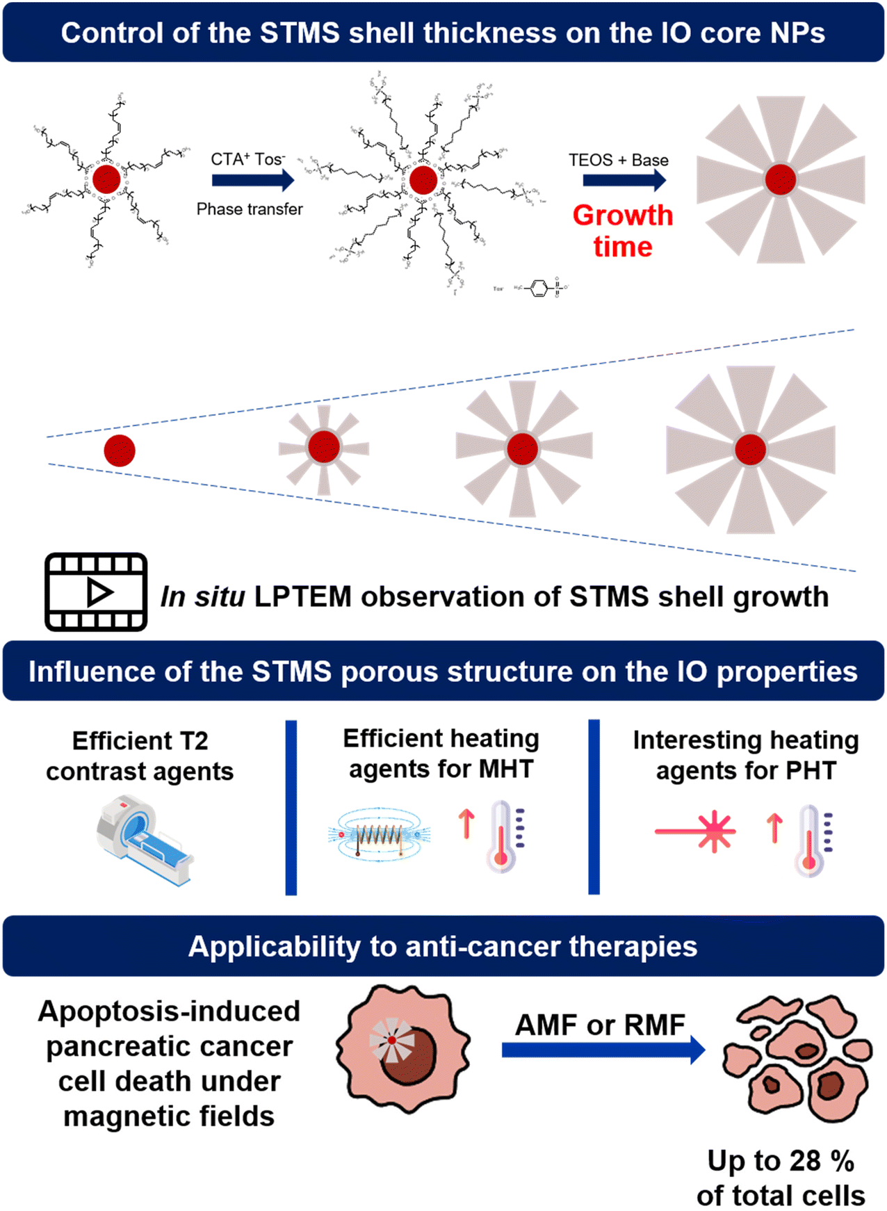
Core–shell nanocomposites made of iron oxide core (IO NPs) coated with mesoporous silica (MS) shells are promising theranostic agents. While the core is being used as an efficient heating nanoagent under alternating magnetic field (AMF) and near infra-red (NIR) light and as a suitable contrast agent for magnetic resonance imaging (MRI), the MS shell is particularly relevant to ensure colloidal stability in a biological buffer and to transport a variety of therapeutics. However, a major challenge with such inorganic nanostructures is the design of adjustable silica structures, especially with tunable large pores which would be useful, for instance, for the delivery of large therapeutic biomolecule loading and further sustained release. Furthermore, the effect of tailoring a porous silica structure on the magneto- or photothermal dissipation still remains poorly investigated. In this work, we undertake an in-depth investigation of the growth of stellate mesoporous silica (STMS) shells around IO NPs cores and of their micro/mesoporous features respectively through time-lapse and in situ liquid phase transmission electron microscopy (LPTEM) and detailed nitrogen isotherm adsorption studies. We found here that the STMS shell features (thickness, pore size, surface area) can be finely tuned by simply controlling the sol–gel reaction time, affording a novel range of IO@STMS core@shell NPs. Finally, regarding the responses under alternating magnetic fields and NIR light which are evaluated as a function of the silica structure, IO@STMS NPs having a tunable silica shell structure are shown to be efficient as T2-weighted MRI agents and as heating agents for magneto- and photoinduced hyperthermia. Furthermore, such IO@STMS are found to display anti-cancer effects in pancreatic cancer cells under magnetic fields (both alternating and rotating).
I. Introduction
Nowadays, a true challenge in the field of nanomedicine is the development of multifunctional materials that could be used to perform imaging, drug delivery and other innovative therapies using a single platform, allowing the reduction of side effects and the improvement of diagnosis and therapeutic efficiency.1,2 Among the potential materials, core–shell iron oxide@silica nanoparticles (IO@silica NPs) are particularly interesting systems as the association of these two materials naturally combines several advantageous properties. Indeed, IO NPs are already commercially used for magnetic resonance imaging (MRI) as they are very good T2 contrast agents.3–6 In addition, they are recognised as efficient heating agents under an alternating magnetic field (AMF) stimulus3,7–10 and their potential as heating agents by near-infrared (NIR) light irradiation is also emerging.11–14 Last but not least, IO NPs are known to have low toxicity and to be well internalised and degraded by cells,3,4 and given all these features, have great potential for theranostic applications. However, without a robust and efficient coating strategy, they suffer from rapid blood capillary agglomeration and elimination, reducing their efficiency.15,16 Among different coating possibilities (polymers, dendrimers, specific biomolecules, silica16), synthesising a porous silica (MS) shell around IO NPs presents some interesting features. Indeed, the size and shape of silica nanomaterials are tunable, the surface chemistry is versatile and very importantly, silica is recognised as a generally safe material by the FDA.17–19 Furthermore, MS NPs are reported to degrade in vitro and in vivo and the main dissolution product, silicic acid, is reported to be water soluble and non-toxic. Thus, the addition of an MS layer coating to IO NPs is very appealing for medical applications, especially for drug delivery.20–24Such MS shell coatings around IO NPs,20,21,25,26 but also other inorganic NPs,27–30 were usually synthesised using surfactant templating, with the most famous one being cetyltrimethylammonium bromide (CTAB). Control of the shell thickness is one of the crucial features of such a synthesis and it is mainly achieved by the amounts of reactants, as notably shown by Ye et al. with the molar ratio [CTAB]/[Fe3O4].31 Recently, there has been tremendous interest in tuning the pore size, especially to tailor large pores around IO cores. Indeed, the use of CTAB leads to a pore size of ∼3 nm, which is enough for the delivery of small drugs, but the delivery of larger molecules such as proteins, RNA or DNA has gained growing interest these last years.32
Despite the fact that small pore MS coatings with adjustable shell thicknesses were already reported around superparamagnetic IO NPs (size in the range 10–25 nm), the tailoring of porous silica structures and tuned increases of pore size around such NPs remained quite limited. In some approaches, elegant pore size tuning was achieved using the swelling micelle method, which however limits the range of pore size at ca. 3–6 nm.33 Very recently, interesting works have described the tunable design of MS shells having radially oriented pores around a magnetic core through so-called interfacial co-assembly in a bi-liquid phase where the addition of a water non-miscible apolar solvent was used as a way to expand/tune the pore size.34 These works were nevertheless essentially focused on bigger controlled iron oxide-clusters (ca. up to hundreds of nms).35–38 For instance, by investigating different synthesis parameters (surfactant concentration, amount of organic solvent, or silica precursor, reaction temperature, reaction time, etc.), Nemec and Kralj have developed versatile silica–shell morphologies around a wide range of magnetic inorganic cores, having hierarchical dual pore sizes from ∼3 to ∼40 nm, with centre-radial and raspberry-like pore geometries.36 In another work, Fiedler et al.38 have developed a powerful approach for synthesizing different silica shells of various thicknesses and porosities in the range ca. 5–10 nm that can be adjusted independently around IO cluster cores of various sizes, especially by changing the composition of the cyclohexane/TEOS phase.
As addressed in this present article, the pore increase can also be obtained by another method adapted from K. Zhang et al.39 where CTA+, counterion tosylate (CTATos) is used to orient the silica structure towards stellate mesoporous silica STMS having a pore size of ca. 10–15 nm. Previously in our team, we synthesized and developed core-free STMS and core@shell IO@STMS (where IO NPs are made by thermal decomposition) for biological and environmental applications40–43 and the IO@STMS NPs were notably shown to be suitable systems for MRI, MHT and PHT.44–46 However, these IO@STMS core–shell nanostructures have been synthesised only at a given final core–shell size (ca. 120 nm) and to date, no work has reported in depth the growth mechanism of the STMS shell around IO NP cores or the possibilities to design IO@STMS NPs having a tailored shell structure and their resulting properties for nanomedicine applications (textural pore structure, colloidal stability, response under magnetic fields or NIR light…).
Hence to the best of our knowledge, there is no report that makes use of CTATos as a porogen surfactant combined with a controlled sol–gel reaction time applied around ca. 25 nm size iron oxide NPs (synthesized by thermal decomposition) to generate individual core@shell structures with tunable growth and pore structure (from 7 to 16 nm). Worthy of note is that in all the previous mentioned reports, no investigation of the silica pore structure effects on magneto- and photothermal dissipation and MRI properties was reported, and approaches based on the visualisation in real time through the in situ liquid phase TEM (LPTEM) method of the silica growth were not yet proposed.
In this work, we report the great control of the stellate mesoporous silica shell growth around these IO NPs, to afford a range of IO@STMS core–shell NPs designed with a tunable silica shell. First, with the aim of evidencing the silica shell growth with its reaction time around the IO NP core, we investigated the growth kinetic of STMS shells by time-lapse TEM imaging of the NPs taken out at different time-points of the synthesis and by performing in situ LPTEM imaging to have direct observation of the STMS shell growth. Then, using different synthesis times corresponding to different shell growths, denoted IO@STMS-t (t = 40, 60, 120 min, growth time), we deeply investigated the textural pore size properties (microporosity, mesoporosity) and the colloidal stability of these tunable core–shell NPs. We then evaluated the responses of the different IO@STMS-t NPs under external fields (magnetic field and NIR light) and the effects of pore structure or shell thickness were discussed. Hence, their potential as T2 contrast agents for MRI was evaluated by measurements of their relaxivities, and their potential as good heating agents for MHT and PHT was evaluated by specific absorption rate (SAR, W g−1) measurements. Finally, the potential use of such IO@STMS-t NPs for anti-cancer applications was evaluated by investigating their cytotoxicity towards the pancreatic cancer cell line MIA Paca-2 in the presence and absence of magnetic field stimuli (alternating and rotating). The main concept of this work is represented in Scheme 1.
 | ||
| Scheme 1 Representative scheme of the study. | ||
II. Materials and methods
II.1. Materials
All materials were used as provided. Anhydrous absolute ethanol (EtOH, CAS 64-17-5), chloroform (CHCl3, CAS 67-66-3), nitric acid 65% (HNO3, CAS 7697-37-2), and acetone (C3H6O, CAS 67-64-1) were purchased from Carlo Erba Reagents. Dibenzylether (DBE, CAS C14H14O, CAS 103-50-4) and squalane (C30H62, CAS 111-01-3) were purchased from Acros Organics. Cetyltrimethylammonium p-toluene sulfonate (CTATos, CAS 138-32-9) and Trizma® base (AHMPD, CAS 77-86-1) were purchased from Sigma Life Science. Tetraethylorthosilicate (TEOS, CAS 78-10-4) was purchased from Aldrich chemistry, oleic acid (C18H34O2, CAS 112-80-1) from Alfa Aesar, ferric chloride (FeCl3, CAS 7705-08-0) from Sigma Aldrich, PBS from Sigma and sodium stearate (C18H35NaO2, CAS 822-16-2) from TCI. Iron and indium (115In) plasma emission standards, 1 g L−1, were purchased from AccuStandard.For in vitro experiments, dimethylsulfoxide (DMSO, C2H6SO, CAS 67-68-5) and 3-(4,5-dimethylthiazolyl-2)-2,5-diphenyltetrazolium bromide (MTT, C18H16BrN5S, CAS 298-93-1) were purchased from Sigma, and penicillin–streptomycin (P4333) was purchased from Sigma-Aldrich. Dulbecco's Modified Eagle's Medium (DMEM, GlutaMAX™) and phosphate-buffered saline (PBS) were purchased from Life technologies. Foetal bovine serum (FBS) was purchased from Eurobio Scientific.
II.2. Synthesis of IO NPs
Thermal decomposition was used to synthesise oleic acid-stabilised iron oxide nanospheres with a mean diameter of around 20 nm following a recently reported procedure.47 Briefly, iron stearate(III) was prepared by precipitation of sodium stearate and ferric chloride salts in an aqueous solution as described.48 Then, 1.85 g (2 mmol) of the synthesised iron(III) stearate was mixed with 1.89 g of oleic acid (6.7 mmol) in a two-neck round-bottom flask in 19.5 mL (15.8 g) of squalane and 0.5 mL (0.53 g) of DBE. The mixture was heated at 120 °C and kept at this temperature for 60 min. The condenser was then connected to the flask and the solution was heated to 330 °C prior to being kept under reflux for 60 min under air. After cooling to room temperature, the viscous suspension was solubilised in 10 mL of chloroform. The NPs were precipitated by the addition of an excess of acetone and washed three times with chloroform and acetone (ratio 1![[thin space (1/6-em)]](https://www.rsc.org/images/entities/char_2009.gif) :4, centrifugation 14000g, 5 min). The NPs were then redispersed in chloroform and stored until further use.
:4, centrifugation 14000g, 5 min). The NPs were then redispersed in chloroform and stored until further use.
II.3. Resuspension of IO NPs in deionised water
For some characterisations, oleic-acid-coated IO NPs were further coated with CTA+ surfactant with the aim of re-dispersing them in deionised water (dH2O). To do so, 19.2 mg of CTATos was dissolved in 2 mL of dH2O at 50 °C under stirring in a 5 mL glass vial. Then, the stirring was increased to 950 rpm and 488 μL of the IO solution at 4.1 mgFe mL−1 in chloroform was added to the vial. The temperature was then increased to 65 °C and the solution kept under this vigorous stirring until full evaporation of the chloroform. The final solution was a 1 mgFe mL−1 IO NP colloidal solution in dH2O.II.4. Synthesis of IO@STMS-t NPs
The protocol was used as described previously44–46 with some standardisations. Here, this procedure is described for IO NPs of 26.6 ± 2.1 nm. The amount and volume of IO NP solution are adapted with the IO NPs’ diameter. In a 50 mL round bottom flask, 240 mg of CTATos was dissolved in 25 mL of dH2O at 50 °C (oil bath) under stirring (300 rpm). Then, 27.6 mg of AHMPD pH buffer salt was added and dissolved. The stirring was then increased to high speed (950 rpm) prior to the addition of an adequate quantity of IO NPs in chloroform (31.91 mg, corresponding here to 7 mL). The oil bath temperature was increased to 65 °C to evaporate the chloroform. The mixture changed from hazy grey after addition of the IO NPs to limpid dark black after the evaporation of the chloroform. The mixture was left under stirring for ten additional minutes to be sure that all the chloroform was evaporated before increasing the temperature to 70 °C. Once the temperature of the oil bath was stabilised, the mixture was left under stirring for 30 min to let its temperature stabilise too, prior to the addition of 1.5 mL of TEOS drop by drop for one min. The stirring was then reduced to 750 rpm and left for reaction.For the kinetic study, a sample was collected at 5–10–20–30–40–50–60–90–120 min, quickly cooled with an ice bath and washed twice with EtOH (15000g, 10 min). Without a kinetic study, the reaction was left for 40–60–90 and 120 min (series 1 and 2).
After reaction, the NPs were collected by centrifugation (12000g, 20 min) and washed twice with 15 mL of EtOH (12000g, 12 min). The CTATos was then extracted by dispersing the NPs in 20 mL of NH4NO3 (20 mg mL−1 in EtOH) and heated at 70 °C under stirring. The extraction was then followed by two washings with 15 mL of dH2O and two washings with 15 mL of EtOH (12000g, 12 min). The extraction status was followed by the zeta potential in dH2O as it was positive before extraction (∼30 mV) and became negative when all the CTATos was extracted (∼−20 mV). Here, a first extraction was performed for one night and a second for 1 h. The zeta potential was then stable, meaning that all the CTATos was removed. The NPs were then resuspended in EtOH prior to being used.
The particles were washed three times with dH2O prior to being used for MRI, MHT or PHT properties evaluation. Particles were designated as IO@STMS-t with t being the STMS growth time.
II.5. In vitro biological experiments
Prior to use, the NPs (80 μL) were washed once with dH2O prior to being resuspended in cell culture medium (centrifugation 12000 rpm, 10 min).
000 rpm, 10 min).
000 rpm, 10 min).
II.6. Characterisation methods
In vitro samples were imaged using a Hitachi HU12A (Japan) TEM instrument operating at 75 kV. After their incubation with IO@STMS-t NPs (t = 40, 60, 120) at 5 μgFe mL−1 for 72 h, the cells were washed with PBS and fixed with 4% glutaraldehyde in Sorensen buffer for 4 h at 4 °C. After the washes, the cells were post-fixed in 1% osmium tetraoxide (osmium 2%, saccharose 0.25 mol L−1, Sorensen buffer 0.05 mol L−1) for 1 h at 20 °C, followed by washing with distilled water and uranyl acetate 2% for 12 h at 4 °C. After dehydratation, 70 nm sections of cells embedded in EMbed 812 resin were stained with uranyl acetate and lead citrate. The samples could then be imaged.
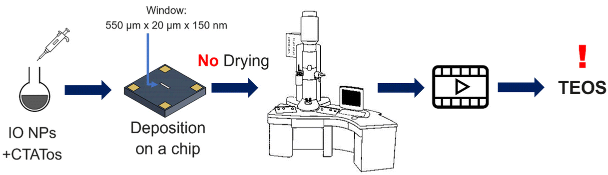
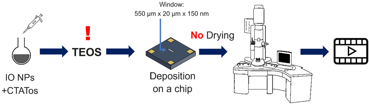
For these experiments, a Protochips liquid cell holder (Poseidon Select 510) was used for the in situ LPTEM analyses. The liquid cell holder contained a removable microchip composed of two Si3N4 membranes that isolated the liquid sample from the ultrahigh vacuum from the TEM column. The dimensions of the E-chip used in this work were 2 × 2 mm2 or 6 × 4.5 mm2. The thickness of the Si3N4 membranes was 50 nm, and the space between each membrane was 150 nm. The two microchips were washed in HPLC-grade acetone for ∼2 min to remove a protective film and then washed with ethanol for 2 min to clean the Si3N4 membranes and they were submitted to plasma cleaning with an Ar/O2 mixture for 30 s.
One of the microchips was placed on the in situ holder where a volume of 1 μL of the IO NPs was added. The second chip was then positioned on top to seal the liquid system (see Fig. S1† for a schematic representation). The sample holder containing the NPs was inserted into the microscope and TEOS was added by flow. Images were recorded using AXON Studio software. Images were exported from AXON studio and analysed with ImageJ.
Zeta potential measurements were recorded in triplicate at 25 °C using a DTS1070 folded capillary cell. The measurements were conducted in dH2O at a concentration of NPs of 0.2 mg mL−1 or in PBS buffer (pH 7.4) when checking the extraction of the CTATos.
II.6.6.1. By NMR 1H-relaxometry. T 1 relaxation time measurements were used to quantify the amount of iron in the NPs for series 1 of IO@STMS-t NPs. To do so, 100 μL of IO@STMS-t NPs was collected and dried. Then, 323 μL of HNO3 (65%) was used to completely dissolve the IO@STMS-t NPs. Some heating at 60 °C could be used to help this digestion step. The sample was diluted precisely in a 10 mL calibrated flask and the T1 relaxation was measured. The amount of iron was determined using a calibration curve established by measuring the longitudinal relaxivity r1 of a standard solution of iron(III) nitrate at 2% of HNO3 (calibration curve presented in Fig. S2†). The variation of the relaxation rates (1/T1) as a function of [Fe3+] from 0 to 3.6 mmol L−1 was plotted and used for the calculations.
II.6.6.2. By inductively coupled plasma-mass spectrometry (ICP-MS). The iron content for series 2 of IO@STMS-t NPs and of the biological samples collected from the cellular uptake experiments was measured on an Agilent 8900 ICP-MS Triple Quad instrument. First, the cells were resuspended in 500 μL of dH2O in order to be transferred to a glass vial for their digestion with 323 μL of HNO3 (65%) for one night. The samples were then partially diluted in dH2O, filtered with a 0.45 μm sterile PES syringe filter, and then diluted to 10 mL using a calibrated flask. The amount of acid was then reduced for the ICP-MS analysis by diluting 1.60 mL of sample to a final volume of 5 mL. Indium (10 ppb) was added as internal standard. Linear calibration functions were obtained (r2 of ≥0.999) and are presented in Fig. S3.†
| Ri = R0i + ri × [IO@STMS] | (1) |
II.6.8.1. By AC magnetometry. The heating efficiency of IO@STMS-t NPs was measured by AC magnetometry using the AC Hyster™ setup from NanoTech Solutions with pick-up coil technology.49 To do so, 40 μL of aliquots of freshly sonicated suspensions of IO NPs in chloroform at 3.35 mgFe mL−1 or of IO@STMS-t NPs in EtOH at 0.5 mgFe mL−1 (thus 4.6 mgIO mL−1 and 0.69 mgIO mL−1 respectively) was introduced into 3 mm diameter 4 inches length NMR tubes (VWR, France). The magnetisation cycles M(H) were then measured three times with a delay of 45 s between each measurement at a frequency f of 280 kHz and an amplitude H of 20 kA m−1. Further measurements were performed some days later after sonication at 280 kHz or 217 kHz and 24 kA m−1. The measured cycles were averaged and normalised by the exact weight of IO present in the tube to get the mass magnetisation in A m2 kg−1.
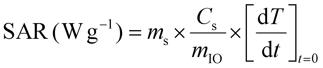
II.6.8.2. By calorimetry. The temperature profiles under an AMF stimulus were performed using a D5 series instrument equipped with a G2 multi-mode 1500 W driver (NanoScale Biomagnetics™, nB) and a CAL1 coil under MaNIaC™ software. Standard HPLC 1.5 mL vials well adapted for magnetothermal measurements were used and filled with 1 mL of IO-CTA+ or IO@STMS-t NPs at 0.5 mgFe mL−1 in dH2O. An AMF with a frequency f of 303.50 kHz and an amplitude H of 300 G (24 kA m−1) was applied and the temperature profiles were recorded for 5 min.
 | (2) |
 | (3) |
In order to compare the heating efficiency of NPs between different labs or studies, the ILP can be calculated following eqn (4):
 | (4) |
III. Results and discussion
III.1. STMS growth on IO NPs through TEM imaging
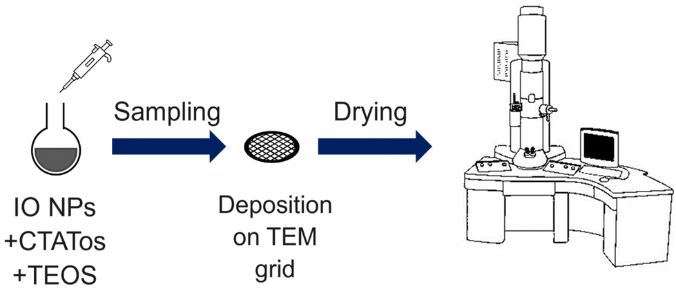
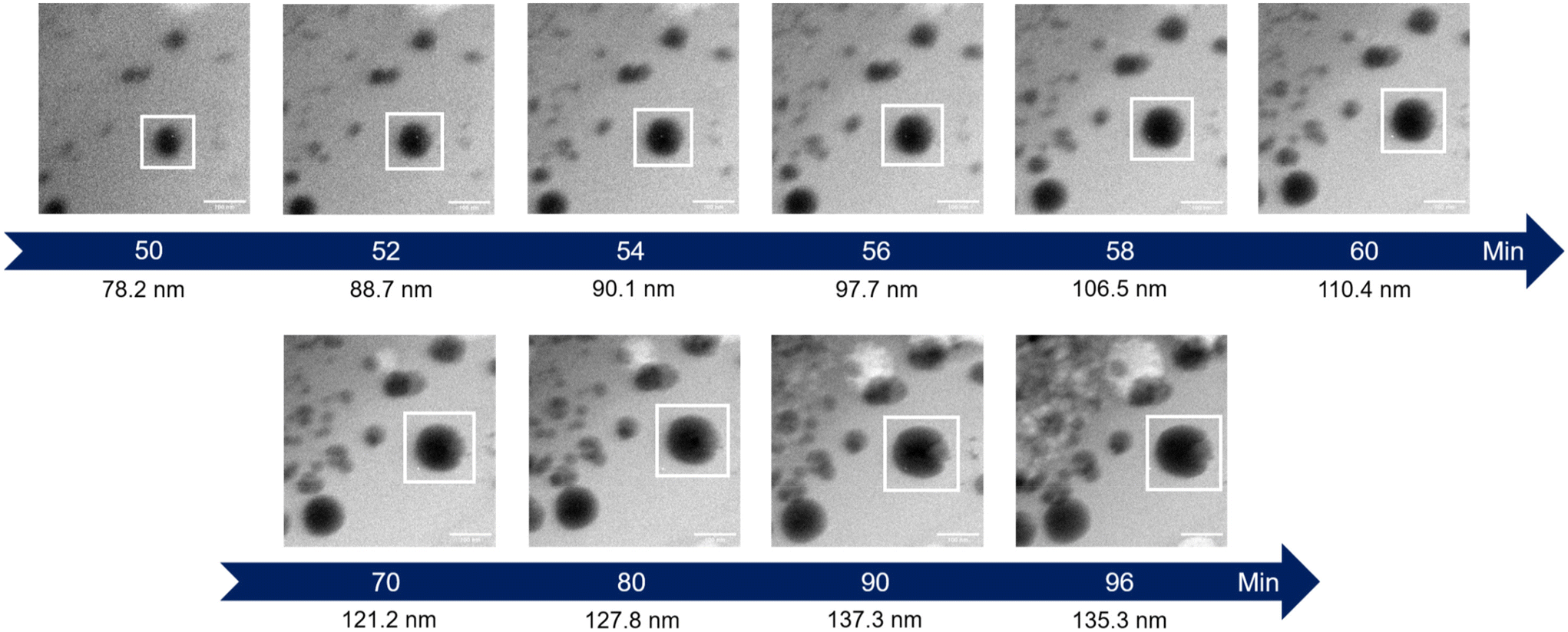
The very first step of our study was to evaluate the possibility to control the STMS shell growth around the IO NP core. To do so, we performed the “120 min” classical synthesis as described in the Materials and methods section (II.4.) and collected a sample at different time points. The reaction in the sample aliquot was stopped by immersion in an ice bath and the particles were then washed prior to being imaged by TEM, as represented in Scheme 2. The obtained time-lapse of the reaction with the corresponding particle size distribution is presented in Fig. 1. As can be seen, a few condensed silica spicules around the IO NPs can be observed at 5, 10, 20 and 30 min post-addition of TEOS, but a good silica layer with stellate morphology can be seen from 40 min. Its growth is then clearly observable at 50, 60, 90 and 120 min.
 | ||
| Scheme 2 Schematic representation of the procedure followed to perform the time-lapse TEM imaging. | ||
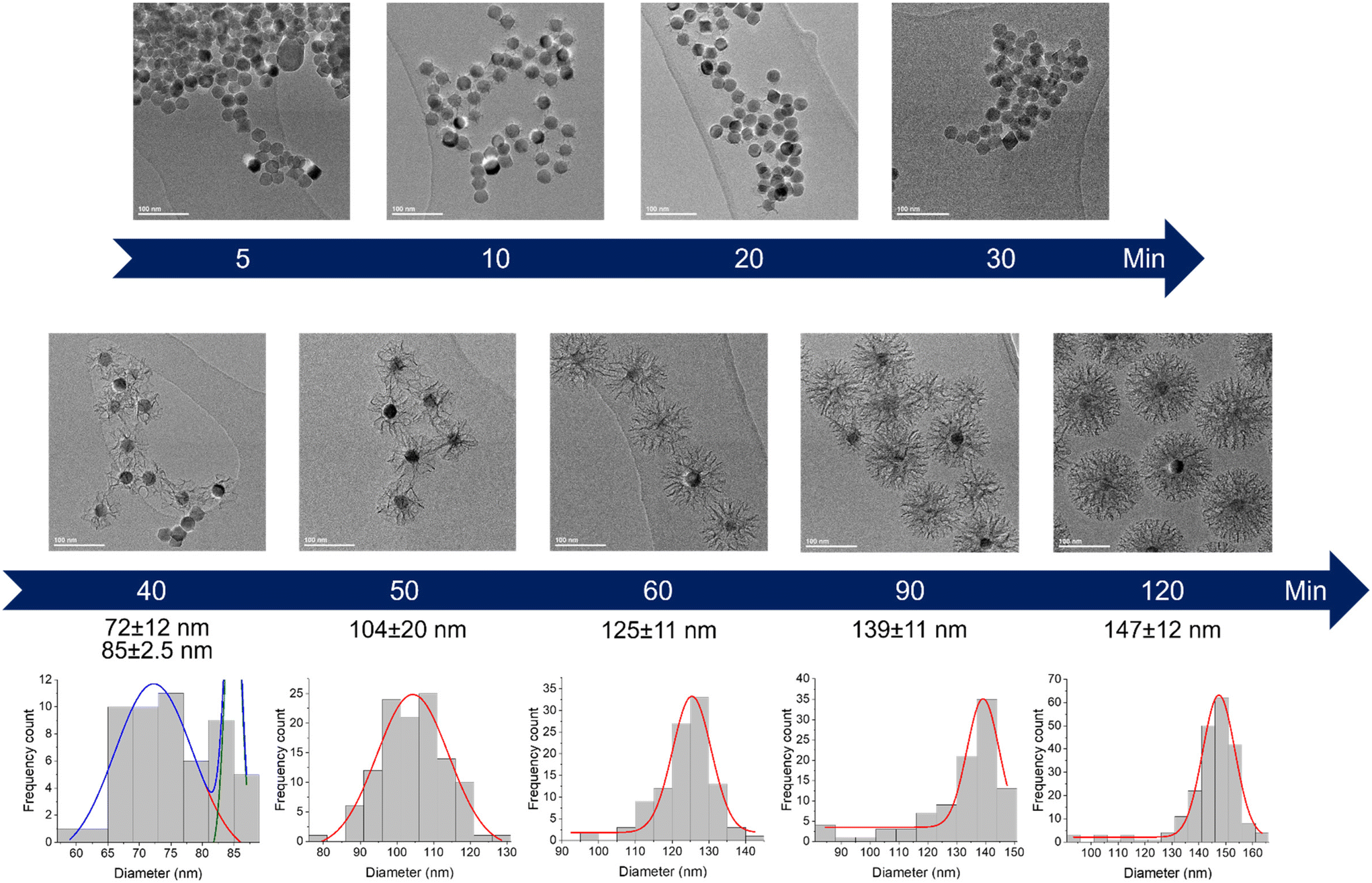 | ||
| Fig. 1 Kinetic tracking of STMS growth on IO NPs by TEM with the corresponding IO@STMS NPs diameter distribution analysed by Gaussian fit. | ||
EDX measurements were also performed on the samples (Fig. 2A) and show a start of the silica growth between 20 min and 30 min post-addition of TEOS as the Si/Fe mass ratio increased from ca. 0.06 ± 0.03 to ca. 0.13 ± 0.03 and then to ca. 1.03 ± 0.21 at 40 min post-addition of TEOS. Altogether, these analyses show that the STMS growth starts from 30 min post-addition of TEOS but that 40 min of reaction is necessary to get a good STMS shell. The reproducibility of this timing was evaluated on two other syntheses performed on different IO NP batches. The evolution of the final IO@STMS NP diameters determined by TEM is shown in Fig. 2B and confirms that the kinetics of the reaction remains the same from batch to batch.
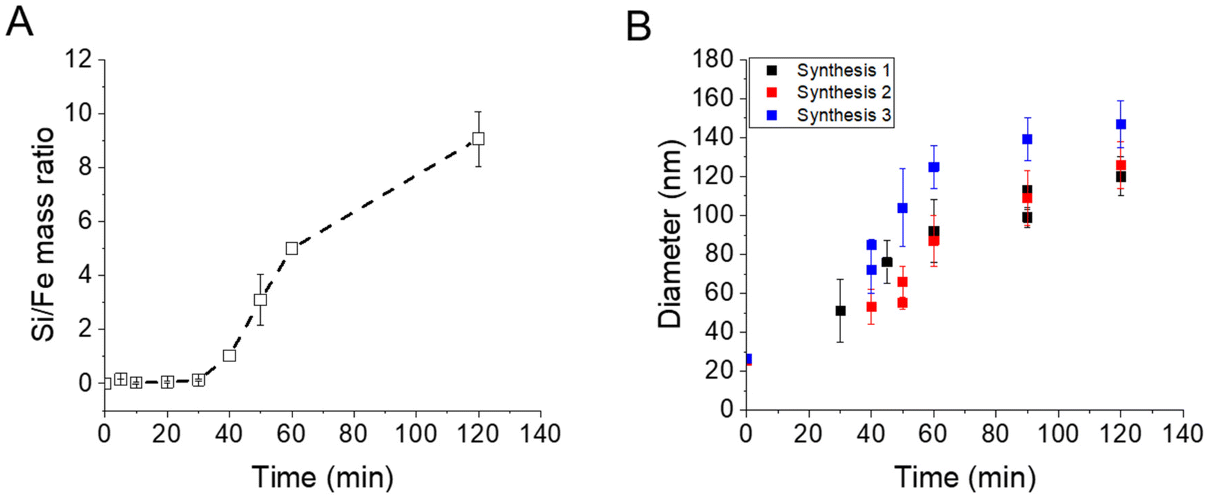 | ||
| Fig. 2 (A) Kinetic tracking of STMS growth on IO NPs by Si/Fe mass ratio obtained by EDX. (B) Evolution of the IO@STMS NP final diameters measured by TEM on three different syntheses. | ||
All these experiments show that we can modulate the STMS shell thickness around the IO NP core by simply playing on the synthesis time and by taking into consideration that a minimum of 40 min of reaction is necessary to get a minimal STMS shell.
 | ||
| Scheme 3 Schematic representation of the procedure followed to perform the first in situ LPTEM experiment. | ||
 | ||
| Fig. 3 Time-lapse images extracted from the in situ LPTEM video ESI Video 1.† The white box represents an interesting particle whose diameter is measured on the last images. | ||
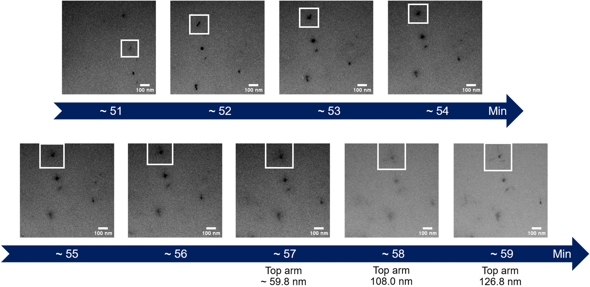
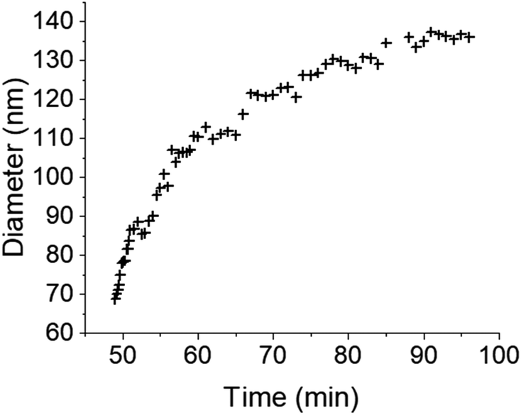
The initial experiment provided an insightful glimpse into the silica growth on the IO NPs. However, we identified two key limitations: uncertainty regarding the timing of TEOS introduction into the cell, and concerns about the homogeneous dilution of TEOS on the cell. Thus, we performed a second experiment where we added the TEOS to the IO NP suspension before adding the solution to the chip for in situ LPTEM observation, as represented in Scheme 4. The resulting video is given in ESI Video 2,† and the corresponding time-lapse is given in Fig. 4. The growth of the STMS shell can clearly be seen by the increase in size of most of the particles visible in the selected region. The diameter of one particle was measured all along the duration of the video, which here corresponds precisely to the time post-addition of TEOS. As evident from the extracted time-lapse series (Fig. 4) but also from the graph presented in Fig. 5, the growth was quite fast between 50 and 60 min post-addition of TEOS, with a growing speed estimated at 8.1 ± 0.5 nm min−1, but then it slowed down. This variation in growth kinetic compared with the experiment may stem from the confined conditions employed, without any stirring and thus also under diffusion-limited conditions.
 | ||
| Scheme 4 Schematic representation of the procedure followed to perform the second in situ LPTEM experiment. | ||
 | ||
| Fig. 4 Time-lapse images extracted from the in situ LPTEM video ESI Video 2.† The white box shows the particle whose diameter is indicated under the images. | ||
 | ||
| Fig. 5 Evolution of the IO@STMS NP final diameters measured on the in situ LPTEM images from ESI Video 2.† | ||
These two attempts of in situ LPTEM imaging allowed us to obtain two complementary videos, one showing the “arm” structure of the stellate silica around the IO NPs, and the second showing the homogeneous growth of the silica shell on the IO NPs core.
III.2. Pore structure characterisation of tailored IO@STMS-t NPs
In a second step, we wanted to finely characterise the structural features of IO@STMS NPs having tuned shell thicknesses. For the sake of clarity, we denote the different batches as IO@STMS-t where t represents the growth time for the rest of the study, and chose the times according to the previous results: 40, 60 and 120 min. It is noteworthy that IO@STMS-t NPs usually come from the same IO NP batch, but sometimes also from another IO NP batch of very similar diameter. Such cases will be specified.Fig. 6 shows the synthesised particle batches from the first series (denoted series 1 for the rest of the study). The IO@STMS-120 were the ones obtained by performing the kinetic study. The IO@STMS-40 and IO@STMS-60 were synthesised in other experiments, whose respective diameters measured on TEM images correlate very well with the ones taken out during the kinetic study, as we got a diameter here of ca. 87 ± 18 nm versus ca. 85 ± 2.5 nm during the kinetic study for 40 min of reaction and ca. 121 ± 14 nm versus ca. 125 ± 11 nm for 60 min, showing again the good reproducibility of the synthesis and feasibility of the control of the STMS shell thickness.
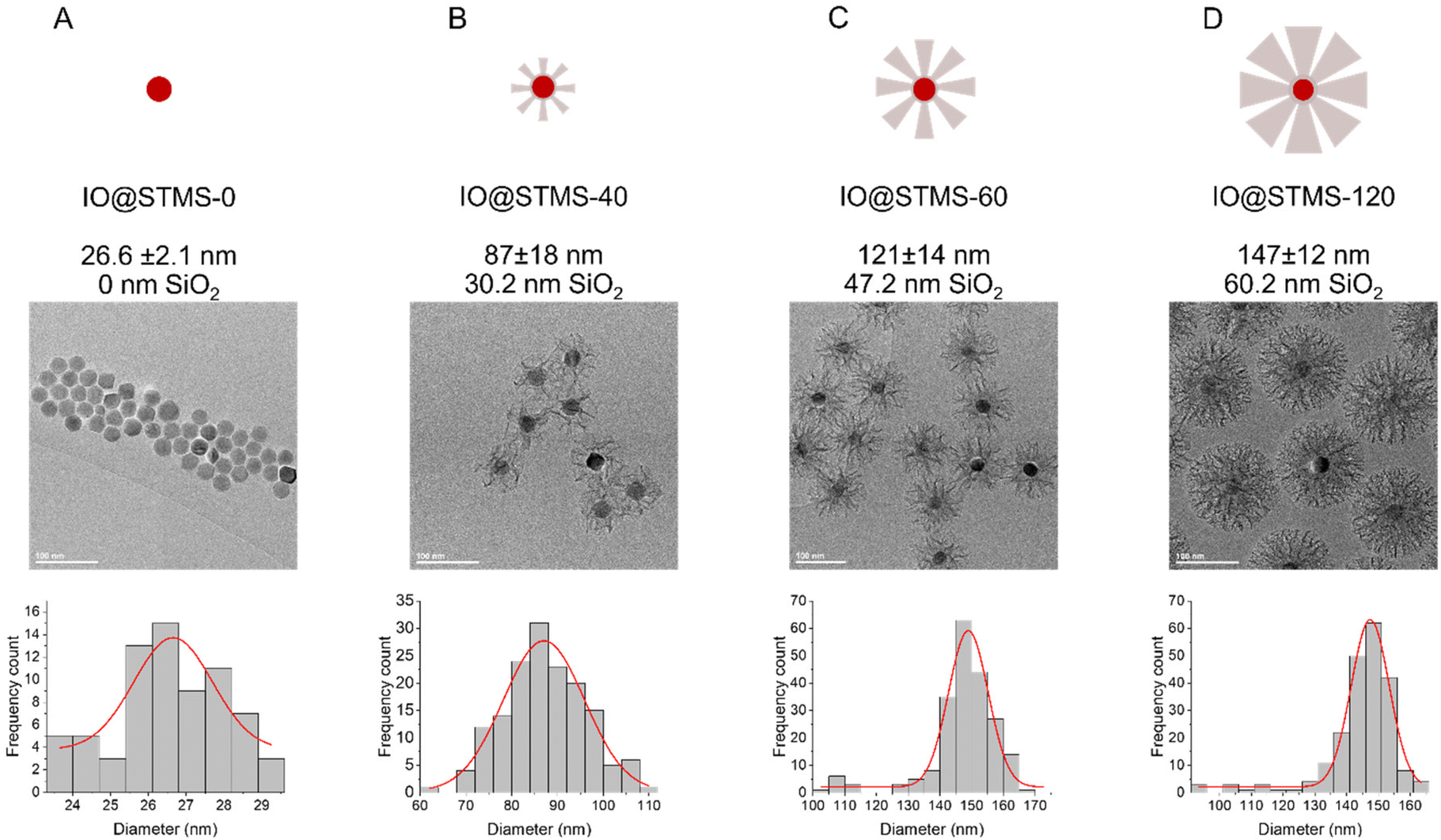 | ||
| Fig. 6 Schematic representation, TEM and distribution of diameters for (A) IO@STMS-0, (B) IO@STMS-40, (C) IO@STMS-60 and (D) IO@STMS-120 obtained from series 1. | ||
We then characterised the porous texture/structure of the IO@STMS-t by nitrogen adsorption–desorption measurements in order to get precise information on the structural characteristics of the particles in terms of surface area, pore size, and pore volume (Fig. 7). We also added IO@STMS-90 to this porous texture study as it gave the same diameter as the IO@STMS-120 (ca. 149 ± 12 nm, see Fig. S6† for the TEM characterisation). In addition, for this characterisation, we had to synthesise a new batch of IO@STMS-40 due to the very low quantity obtained for the batch presented in Fig. 6 (see Fig. S7† for the TEM characterisation).
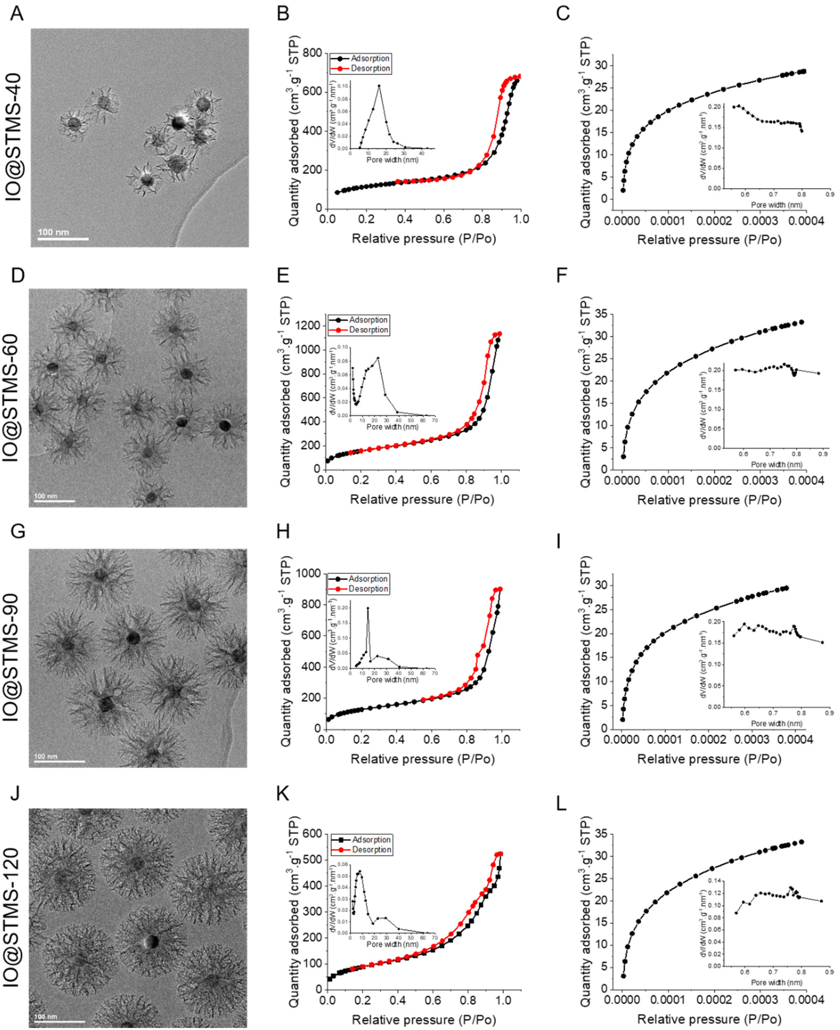 | ||
| Fig. 7 TEM images (issued from Fig. 6, Fig. S6 and S7†), adsorption–desorption isotherms at high relative pressures including an inset with the BJH desorption pore volume plot, and adsorption isotherms at small relative pressures including an inset with the Horvath–Kawazoe differential pore volume plot for IO@STMS-40 (A–C), IO@STMS-60 (D–F), IO@STMS-90 (G–I) and IO@STMS-120 (J–L). | ||
The nitrogen adsorption–desorption curves are presented in Fig. 7 and the BET surface (SBET), pore volume (V) and representative pore size (Dp-) values are regrouped in Table 1. Firstly, the global aspect of the adsorption–desorption isotherms (Fig. 7B, E, H and K) shows the dual micro–mesoporous character of our samples. Indeed, the shape of the curve at a relative pressure up to 0.6, with the small increase and then the plateau, corresponds more to a type I isotherm (according to the IUPAC classification), which is attributed to microporous materials (pore size below 2 nm); while the presence of the sharp increase at higher relative pressures (from 0.8) with the small hysteresis loop corresponds more to a type IV or V isotherm, which is attributed to mesoporous materials (pore size from 2 to 50 nm).56 Unfortunately, the non-representative shape of the hysteresis loop does not allow determination of the pore shape. However, other characteristics could be extracted from the nitrogen adsorption–desorption measurements.
| Sample | S BET (m2 g−1) | V pores (cm3 g−1) | V meso (cm3 g−1) | V micro (cm3 g−1) | D p-micro (nm) | D p-meso (nm) |
|---|---|---|---|---|---|---|
| V meso was determined by integrating the BJH pore volume plot between 5 and 24 nm (a) or between 5 and 18 nm (c). In the specific case of IO@STMS-60, the signal was decomposed to get the participation of the mesopores and the voids and the integration was performed according to the obtained peaks, thus being from 5 to 39 nm (b). Vmicro was determined by integrating the Horvath–Kawazoe differential pore volume plot between 0.5 and 0.8 nm. | ||||||
| IO@STMS-40 | 408 | 1.03 | 0.92 (a) | 0.041 | 0.5–0.8 | 16.1 |
| IO@STMS-60 | 579 | 1.59 | 0.99 (b) | 0.063 | 0.5–0.8 | 15.2 |
| IO@STMS-90 | 466 | 1.16 | 0.70 (c) | 0.056 | 0.5–0.8 | 14.5 |
| IO@STMS-120 | 333 | 0.67 | 0.52 (c) | 0.034 | 0.5–0.8 | 7.7 |
Secondly, the BET surface area could be determined and it is clear that the value decreases as the silica growth time increases, as it dropped from ca. 579 m2 g−1 for IO@STMS-60 to ca. 466 m2 g−1 and ca. 333 m2 g−1 for IO@STMS-90 and IO@STMS-120 respectively. The global pore volume followed the same trends, as it dropped from ca. 1.59 cm3 g−1 for IO@STMS-40 to ca. 1.16 cm3 g−1 and ca. 0.67 cm3 g−1 for IO@STMS-90 and IO@STMS-120 respectively. These first observations mean that increasing the reaction time allows the STMS shell first to grow rapidly in a radial way (from the NPs to the exterior), thus getting a higher silica shell thickness with large openings and thin walls, and then to condense inside the pores, thus getting a denser shell and thicker walls. One can object that the BET values and the global pore volume measured for the IO@STMS-40 are smaller (ca. 408 m2 g−1 and ca. 1.03 cm3 g−1 respectively) than the ones for IO@STMS-60 and thus do not follow the trend, but this is actually logical as the particles are still very small, especially for the batch used for this measurement. However, this kind of mechanism of STMS shell growth, that we represented in Scheme 5, is in great correlation with what is observed by TEM: we can clearly see large pores in the TEM picture “40 min” that we do not longer see in the TEM picture “120 min” in Fig. 1, and the thin wall reminds us of the silica “arms” seen in the first in situ LPTEM experiment (Fig. 3 and Fig. S5†). In addition, the comparison of IO@STMS-90 and IO@STMS-120 leads to the conclusion that even if the radial growth is done, the condensation reaction still occurs, reducing the global pore volume and resulting in a denser silica shell.
 | ||
| Scheme 5 Schematic representation of the STMS shell growth mechanism around the IO NP core. | ||
We nevertheless note that this global pore volume includes the volume of the micropores (Vmicro), the volume of the mesopores (Vmeso) and the void volume corresponding to interparticle spaces. We thus used the Horvath–Kawazoe model (inset in Fig. 7C, F, I and L) and the BJH model (inset in Fig. 7B, E, H and K) to extract Vmicro and Vmeso and respectively their associated representative pore widths. The values reported in Table 1 confirm that we have a micro–mesoporous structure as Vmeso does not corresponds to the total Vpore. The high values of Vmeso compared with Vmicro were expected as, even if the micropores are present in a large amount as ultra-thin channels (around 0.5–0.8 nm diameter), they do not contribute importantly to the total pore volume and the mesopores still represent a largely higher volume. Furthermore, the Horvath–Kawazoe differential pore volume plot does not allow a determination of a representative micropore size. However, the decrease of Vmicro with the increase of growth time is clear, and the quite low value of Vmicro for IO@STMS-120 (ca. 0.034 cm3 g−1) tends to show that the microporous component of the sample has been highly reduced by the silica condensation. The decrease of Vmeso with silica growth time also seems logical given the previous conclusions. Regarding the pore size analysis, the evolution of the BJH desorption pore volume plot is quite interesting. Indeed, the plots show a bimodal distribution for IO@STMS-90 and IO@STMS-120, corresponding to a Dp-meso of ca. 14.5 nm and ca. 7.7 nm respectively, with another small peak around 30 nm that is usually attributed to interparticles voids. However, the plots obtained for IO@STMS-40 and IO@STMS-60 do not show a bimodal distribution, meaning that the mesopores are still quite “open” up to 60 min of synthesis, i.e. large enough not to be very different in terms of interparticle voids on the plot. However, the analysis of these plots allowed the determination of a Dp-meso of ca. 16.1 nm and ca. 15.2 nm for IO@STMS-40 and IO@STMS-60 respectively, which follows the global trends found with IO@STMS-90 and IO@STMS-120.
Altogether, these analyses confirm the micro–mesoporous character of the IO@STMS-t NPs and showed that the radial growth of the STMS shell is accompanied by a continuous silica condensation of the shell, even when the radial growth is stopped.
III.3. Colloidal stability of tailored IO@STMS-t NPs
Finally, the influence of the reaction time and thus of the STMS shell thickness on the colloidal stability of the particles was evaluated in EtOH (Fig. S8†) and in dH2O (Fig. 8). The stability of the IO-CTA+ NPs in dH2O (IO@STMS-0) was quite good after the phase transfer from chloroform to CTATos solution in dH2O. The hydrodynamic diameter was determined to be ca. 45.9 ± 15.9 nm which indicates that some aggregates may be formed even with the surfactant covering. This is in correlation with the aggregation of the particles that we observed after a 24 h aging. Regarding the IO@STMS-t (with t > 0) NPs, the colloidal stability was overall good in both EtOH and dH2O. The size graphs of intensity distribution show some very slight aggregation with the smaller STMS shell thickness and a progressive disappearance of these aggregates with the increase of the STMS shell thickness in both solvents. In addition, the size graphs of number distribution show that these aggregates were very few in the sample as only one peak is visible. Interestingly, the hydrodynamic diameter was found to be ca. 198 ± 2.4 nm (PDI ca. 0.24 ± 0.01), ca. 174 ± 0.3 nm (PDI ca. 0.19 ± 0.02) and ca. 177 ± 0.9 nm (PDI ca. 0.07 ± 0.01) in EtOH and ca. 183 ± 2.4 nm (PDI ca. 0.27 ± 0.02), ca. 163 ± 0.8 nm (PDI ca. 0.18 ± 0.02) and ca. 171 ± 1.1 nm (PDI ca. 0.07 ± 0.02) in dH2O for IO@STMS-40, IO@STMS-60 and IO@STMS-120 respectively, indicating suitable colloidal stability.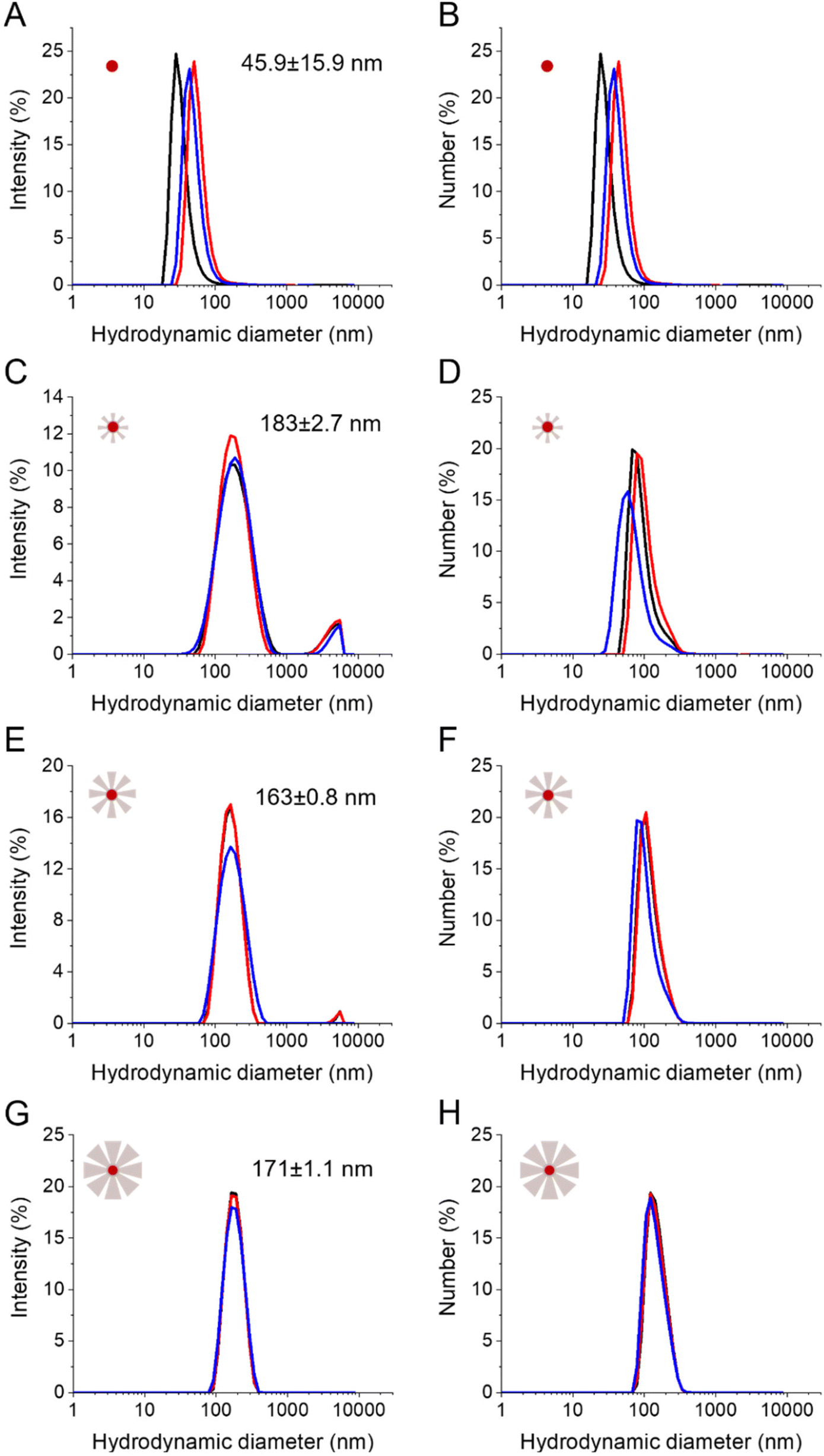 | ||
| Fig. 8 Colloidal stability in dH2O as shown from the distributions of intensity and of the number of hydrodynamic diameters respectively of IO@STMS-0 (A, B), IO@STMS-40 (C, D), IO@STMS-60 (E, F) and IO@STMS-120 (G, H). | ||
The zeta potential of the particles was evaluated in dH2O right after the colloidal stability study (Fig. S9†). The change from a positive value (ca. 45.4 ± 0.6 mV) for IO@STMS-0 to a negative value for IO@STMS-t (ca. −23.5 ± 0.2 mV, ca. −21.6 ± 0.2 mV and ca. −14.8 ± 0.8 mV for t = 40, 60 and 120 respectively) is due to the silica shell around the particles and was used, in practice, as a first indicator of the success of the silica synthesis before any TEM analysis. Given the colloidal stability, and more precisely the disappearance of the slight aggregates when the growth time increases, we were expecting an increase in absolute value of the zeta potential with the increase of growth time, as a higher absolute value would mean a higher electrostatic repulsion and thus a higher stability. However, the trend was the opposite, and this may be explained by the nature of the negative surface charge in silica NPs. Indeed, this negative surface charge comes from the silanolate groups that are coming from easily deprotonated Si–OH groups at the NPs’ surface. When the growth time increases, the surface area decreases and Si–OH may cross-link more into Si–O–Si bridge groups, both effects contributing to reduce the negative zeta value.
Furthermore, we found that IO@STMS with a small STMS shell thickness have a similar/comparable hydrodynamic size to IO@STMS with a bigger shell (in the range 163–183 nm). We figure out that clusters composed of a couple to several NPs are formed for IO@STMS-40 (TEM core shell size of ca. 87 ± 18 nm) while the IO@STMS-120 may be dispersed individually. Factors such as the increase of hydrophilicity of the silica coating combined with the absence/reduction of magnetic dipolar interactions between iron oxide cores may explain this enhanced dispersion state for bigger shells. Conversely, an incomplete growth of silica that may favour H-bond interactions between the surface silanol groups of small STMS shells combined with potential magnetic dipolar interactions would explain their stabilisation into small clusters of several IO@STMS NPs. For instance, the difference of dipolar magnetic interactions existing between citrate-stabilised iron oxide NPs and silica-coated iron oxide was well evidenced by Kesse, Vichery and coworkers using ZFC/FC curves.57
Overall, the DLS analyses show that the increase of STMS shell thickness improves the global colloidal stability of the IO@STMS-t NPs.
III.4. Influence of the STMS shell on the MRI, MHT and PHT properties of IO NPs
We showed in the previous sections that we were able to synthesise IO@STMS NPs with tunable silica shell thicknesses and pore structures. The next step of our study was to investigate the influence of the STMS shell thickness on the MRI, MHT and PHT properties of the IO NP core. From this section, it was particularly important for us to compare IO@STMS-t NPs with the same IO NP core, thus coming from the same series of syntheses. Series 1 presented in Fig. 6 allowed only one measurement for the following experiments. We thus synthesised a second series of IO@STMS-t NPs (denoted as series 2), whose characteristics are given in Fig. S10,† for which we could perform the measurements in triplicate and the in vitro studies with cancer cells presented in the last section of this article.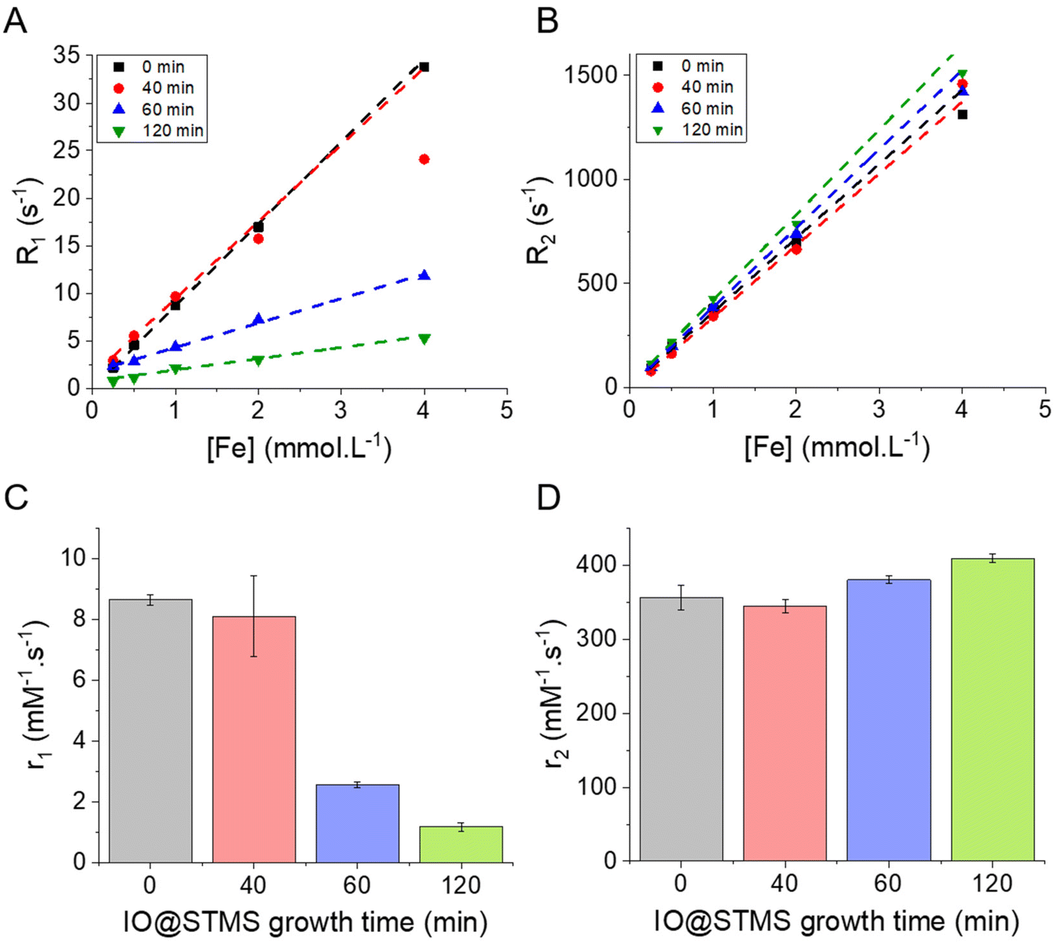 | ||
| Fig. 9 (A) and (B) respectively the longitudinal R1 = 1/T1 (s−1) and transverse R2 = 1/T2 (s−1) relaxation rates as a function of the concentration of iron in the different IO@STMS-t NPs solutions. (C) and (D) respectively the evolution of the longitudinal and transverse relaxivities r1 and r2 as a function of the IO@STMS growth time. These results were obtained with the IO@STMS-t obtained from series 2. | ||
Regarding the transverse relaxivity r2 (Fig. 9D), the value is slightly increased in the presence of the STMS shell, with a very slight increase of the r2 value when the shell thickness increases. Indeed, the r2 went from ca. 356 ± 17 mM−1 s−1 for IO@STMS-0 to ca. 345 ± 9 mM−1 s−1, ca. 380 ± 5 mM−1 s−1 and ca. 409 ± 6 mM−1 s−1 for IO@STMS-40, IO@STMS-60 and IO@STMS-120 respectively. The IO@STMS-t NPs obtained from series 1 gave the same tendency, as shown in Fig. S11D and Table S1.† The first observation that can be drawn here is that the silica shell growth does not influence or hinder importantly these transverse relaxation modes of water protons. This is attributed to the long-range effect of this relaxation mode through dipolar interactions due to the high magnetic moment of the IO NPs. We can notice the slight r2 increases from 0 to t min growth time which may be due to the colloidal stabilization brought by the STMS shell to the IO NPs and the increase of the hydrodynamic diameter, slowing down their Brownian motion and increasing the contact time between the water molecules and the IO NPs during the spin echoes. Importantly, the r2 values are very high compared with commercial T2 contrast agents (Combidex r2 = 65 mM−1 s−1, Ferumoxytol r2 = 89 mM−1 s−1, Resovist r2 = 189 mM−1 s−1)58 showing that these IO@STMS-t NPs are very good T2 contrast agents.46,59,60
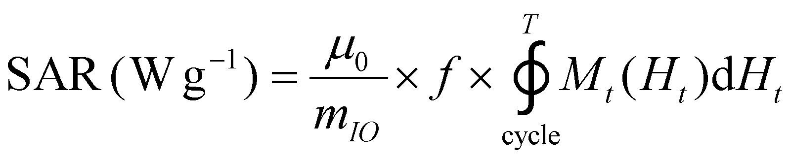
The release of heat from IO NPs under AMF stimulation is usually described as arising from two phenomena: Néel relaxation, which corresponds to the reorientation of the magnetic moment inside the particle, and Brown relaxation, which corresponds to the reorientation of the whole particle in the medium. The heating process depends on several parameters such as the magnetocrystalline anisotropy, the NP volume and the environment viscosity. Usually, the heating capacity of particles is expressed with the specific absorption rate (SAR), which is most often determined by a calorimetric experiment through eqn (3), given in Materials and methods (II.6.10.). Another way to determine the SAR consists of measuring the dynamic magnetization M(t), which exhibits a phase shift compared with the instantaneous AMF vector H(t), creating AC hysteresis loops, even for superparamagnetic IO NPs. In this AC magnetization curve Mt(Ht), the surface area is equal to the heat dissipated during one period of the AMF T = 2π/f, hence the SAR:50
 | (2) |
The magnetothermal properties of the particles obtained from series 2 were evaluated by AC magnetometry using different conditions of frequency/magnetic fields f/H: 280 kHz/20 kA m−1, 280 kHz/24 kA m−1 and 217 kHz/24 kA m−1 for IO@STMS-0 (3.35 mgFe mL−1) and for IO@STMS-t, with t = 40, 60, 120 min (0.5 mgFe mL−1). Representative hysteresis cycles are presented in Fig. 10A–C, where it can be noted that the ones obtained for IO@STMS-0 present a “square shape” rather than opened sigmoids. In previous work by Mille et al.,62 this phenomenon of a large opening of the hysteresis loops was ascribed to the organisation of the particles as chains of NPs during the magnetic field application. The chaining effect was also investigated by Martinez-Boubeta, Serantes and coworkers.63,64 The authors showed experimentally and using modelling that the formation of chain-like structures was explained by more favourable dipolar interaction energy as compared with thermal energy. Computation of hysteresis cycle evolution was achieved as a function of the number of particles within a chain and indicated that hysteresis cycles had more squared shapes and that the area of hysteresis loop increased (and thus SAR values) with the length of the chain.
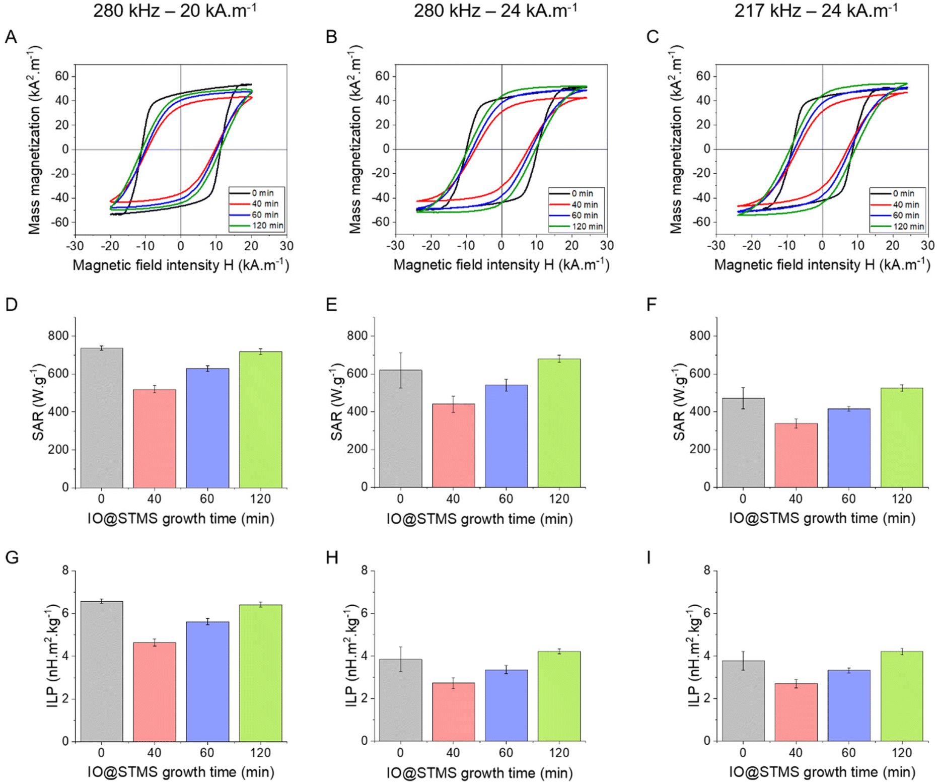 | ||
| Fig. 10 (A)–(C) Representative hysteresis cycles for the different IO@STMS-t NPs (IO@STMS-0 and for IO@STMS-t (t = 40, 60, 120 min)) obtained from series 2 at different frequency–amplitude conditions. (D)–(F) Corresponding SAR values. (G)–(I). Corresponding ILP values. | ||
In our case, macroscopic chains were indeed observed after the AC magnetometry measurement, and could be redispersed by sonication after the measurement. Such chains were also observed on some regions when performing in situ LPTEM imaging (Fig. S12†). This chaining is likely explained by the large diameter of the IO NP cores (dcore = 26.6 nm), which given the measured saturation magnetization of these Fe3−xO4 NPs achieved in Fig. S13† (56.5 emu g−1 hence Ms = 2.83 × 10⁵ A m−1 volume magnetization) leads to a dipolar parameter 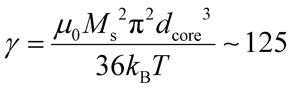 , which explains why the bare IO NPs (without silica) make chains. When the silica layer grows, the dipolar parameter decreases to much lower values
 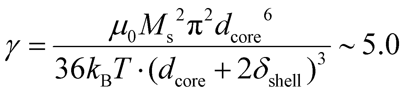 for IO@STMS-40 (δshell = 30.2 nm), ∼2.1 for IO@STMS-60 (δshell = 47.2 nm) and ∼1.4 for IO@STMS-120 (δshell = 60.2 nm).
Regarding the evolution of the saturation magnetization Ms (referred to iron oxide mass) as a function of the silica shell growth presented in Fig. S13,† it is worthy of note that Ms tends to decrease when the silica shell is reduced. The Ms of these samples was measured several months after their synthesis and we hypothesize that when a large silica shell is formed, the oxidized magnetite (Fe3−xO4) is preserved from oxidation with time, while by decreasing the silica shell, oxidation in maghemite (γ-Fe2O3) is favoured, explaining this lowering of Ms.
Looking at the SAR values presented in Fig. 10D (280 kHz and 20 kA m−1) the presence of the STMS shell on the IO NP core tends first to decrease the SAR, as it dropped from ca. 736 ± 11 W g−1 for IO@STMS-0 to ca. 520 ± 20 W g−1 for IO@STMS-40. The SAR values then increased with the increase of STMS growth time as it was measured at a value of ca. 629 ± 16 W g−1 and ca. 718 ± 15 W g−1 for IO@STMS-60 and IO@STMS-120 respectively under the same magnetic field. The same tendency is visible for the two other magnetic fields (Fig. 10E and F) and the global tendency could also be found for the particles obtained in series 1, whose results are presented in Fig. S14 and Table S2.† The global reduction of SAR with the addition of the silica shell is in agreement with previous studies performed in our team65 and could correspond to the disappearance of the observed magnetic chains of iron oxide@CTA+ (IO@STMS-0) when a silica coating is achieved. With a small silica shell, the core–shell reorganised in small clusters which might have a limited Brow relaxation. Then, the increase of the SAR with the increase of the silica shell could come from the better colloidal stability brought by this higher shell thickness, which restores the Brown relaxation mechanism to the heat dissipation.
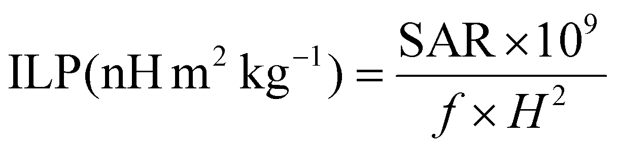
Unfortunately, the SAR values are difficult to compare from one article to another as they are very dependent on extrinsic parameters such as the frequency f and the amplitude H of the applied magnetic field.66 Thus, we calculated the intrinsic loss power (ILP) following eqn (4) given in Materials and methods (II.6.10.), which assumes a linear dependency of SAR with f and quadratic dependency with H, as predicted by the linear response theory for superparamagnetic NPs.67
Such calculations gave us an ILP ranging from ca. 4.64 ± 0.18 to ca. 6.58 ± 0.10 nH m2 kg−1 for series 2 at 280 kHz and 20 kA m−1 (Fig. 10G) and then from ca. 2.7 ± 0.27 to 4.21 ± 0.12 to nH m2 kg−1 when the amplitude is increased to 24 kA m−1 (Fig. 10H and I). The moderate decrease of the SAR and ILP values at 24 kA m−1 can come from the fact that the measurements were performed on the same samples and some days after the ones performed at 20 kA m−1. We suppose here that the chaining effect happened in the first place and was beneficial for the SAR and thus the ILP, while the aging of the samples led to aggregates that could not be completely broken with sonication and thus reduced the ILPs. What can be noted is that these reduced values correlate well with the one obtained for series 1 (from ca. 2.11 nH m2 kg−1 (IO@STMS-40) to ca. 4.08 nH m2 kg−1 (IO@STMS-0) (Fig. S14C and Table S2†)). In addition, such values are quite good compared with the ILP of 1.18 nH m2 kg−1 measured for NanoTherm™68 and compared with the ILPs reported in the literature,10 which is very encouraging for anti-cancer applications using MHT therapies.
Unlike the case of gold and silver NPs, for which it is known that PHT is due to plasmonic resonance under laser irradiation, the mechanism in the case of IO NPs and the parameters influencing the photothermal response are not clearly understood yet. For example, Sadat et al. suggested that the heat generation is due to electronic transitions inside the IO lattice from the valence band to the conduction band.72 Furthermore, even if the mechanism and the parameters are still under debate, it seems that main parameters influencing PHT performances are not the size or shape but more precisely the quality of the crystallographic structure and the presence of defects (vacancies, dislocations, etc.) in the crystal structure. Indeed, in a previous work by Bertuit, Abou-Hassan and co-workers addressing the design of iron oxide nanoflowers having varying levels of defects, nanoflowers having excessive defects in terms of oxygen vacancies were found to decrease the photothermal effects. This was explained by the electron trapping inside the structure decreasing the electron–heat conversion.73
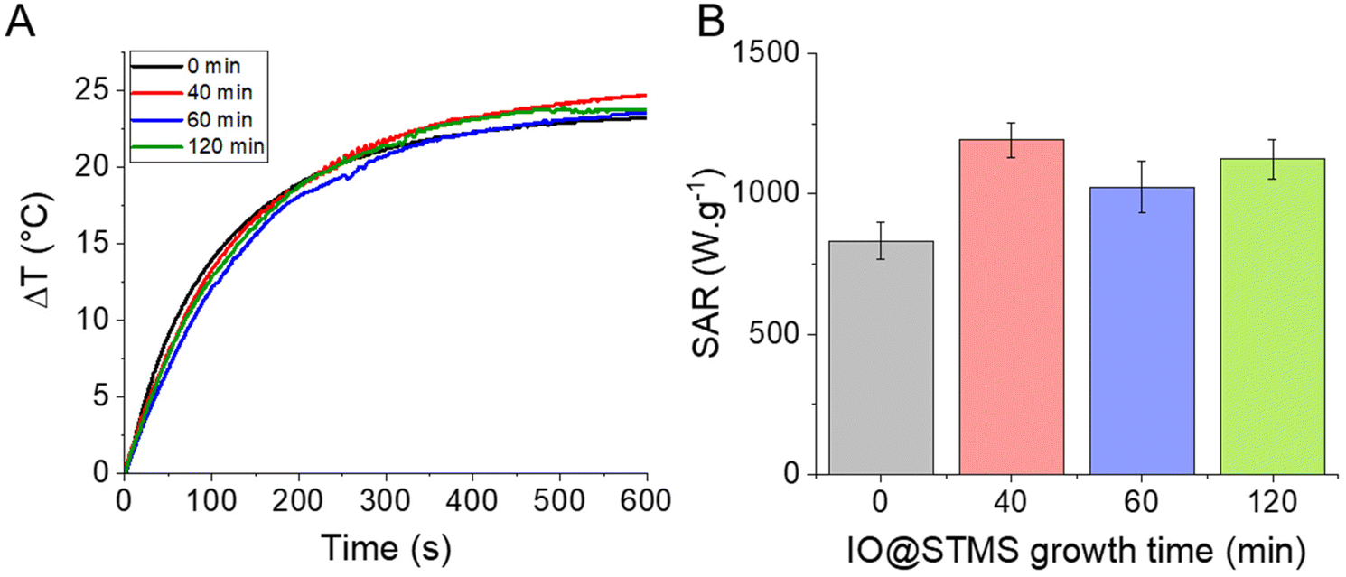
Given all this information, it seemed interesting to us to test the potential of our NPs for PHT therapies. The PHT properties of our IO@STMS-t NPs were thus evaluated using NIR light irradiation at 1064 nm. The NIR laser was applied to the different core–shell NP suspensions at a fixed iron concentration (0.5 mgFe mL−1) and the temperature profiles were plotted and converted into SAR values using the mass of iron oxide as a reference (Fig. 11). Regarding the temperature profile, the final ΔT was found to be quite similar for the IO@STMS-t NPs from series 2, with a slight increase of values between t = 0 (ca. 23.1 ± 0.4 °C) and t = 40, 60 or 120 (ca. 25.2 ± 0.2 °C, ca. 23.9 ± 0.8 °C and ca. 23.8 ± 0.1 °C respectively) while a slight decrease of the values can be seen for the IO@STMS-t NPs from series 1 (ca. 21.9 °C versus ca. 19.1 °C, ca. 19.8 °C and ca. 19.4 °C, Fig. S15†). Taking these results in their totality, they mean that the thermal transfer is overall not affected by the large pore silica shell whatever the thickness.
 | ||
| Fig. 11 (A) Temperature profiles as a function of time for the different IO@STMS-t NPs at 0.5 mgFe mL−1 under NIR light irradiation. (B) Corresponding SAR values. These results were obtained with the IO@STMS-t obtained from series 2. | ||
The final SAR values were determined to be ca. 831 ± 66 W g−1 for IO@STMS-0 and ca. 1191 ± 63 W g−1, ca. 1023 ± 93 W g−1 and ca. 1123 ± 71 W g−1 for IO@STMS-40, IO@STMS-60 and IO@STMS-120 respectively. Regarding the values obtained from series 1 (Fig. S15 and Table S3†), the SAR value decreased slightly with the addition of the STMS shell and then with the growing of the STMS shell thickness (from ca. 909 W g−1 to ca. 712 W g−1). Taking again these results in their totality, it is difficult to really give a tendency for the impact of the STMS shell on the PHT properties of the IO NP core as the values are quite similar whatever the particle series. Unfortunately, a standardisation of the SAR like the calculation of the ILP for magnetothermal measurements is still unavailable for photothermal measurements, making the comparison of our values with the literature difficult. However, the high SAR values and the absence of a clear impact of the silica shell on these SAR values shows the promising aspect of the use of such NPs for PHT therapies.
III.5. Biological features: evaluation of NPs’ applicability to anti-cancer therapies
In the next sections, our goal was to evaluate the potential of our nanoparticles for anti-cancer therapies using magnetic fields as external stimuli. Thus, the pancreatic cancer cell line MIA Paca-2 was chosen, as a model, to perform the in vitro experiments. In addition, as the STMS shell was added to the IO NP core to counteract their rapid blood capillary agglomeration and elimination, IO NPs without an STMS shell were not used for this study.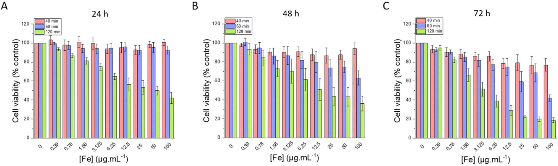 | ||
| Fig. 12 Cell viability evaluated after (A) 24 h, (B) 48 h and (C) 72 h of incubation with different amounts of IO@STMS-t NPs, with t = 40, 60 or 120. | ||
Regarding the chosen concentrations, to give some elements of comparison, in a previous work from our team,46 we previously evidenced a hyperthermia induced-cytotoxic effect on HeLa cancer cells (ca. 65% metabolic activity reduction vs. control) under AMF using human serum albumin-coated IO@STMS-120 at a concentration of 25 μgIO@STMS mL−1 that corresponds to 1.25 μgFe mL−1. Field conditions providing cancer cell viability reduction were at 100 kHz and 357 Gauss (28.4 kA m−1) whose product is below the safety limit of H × f = 5 × 10⁹ A m−1 s−1, commonly accepted for localized hyperthermia.74 Similarly, a concentration of 16 μgFe mL−1 of IO NPs coated with PEG was shown to induce the death of different cancer cell lines (pancreatic, gastric cancer) by intra-lysosomal magnetic hyperthermia (AMF: 40 mT, 275 kHz).75
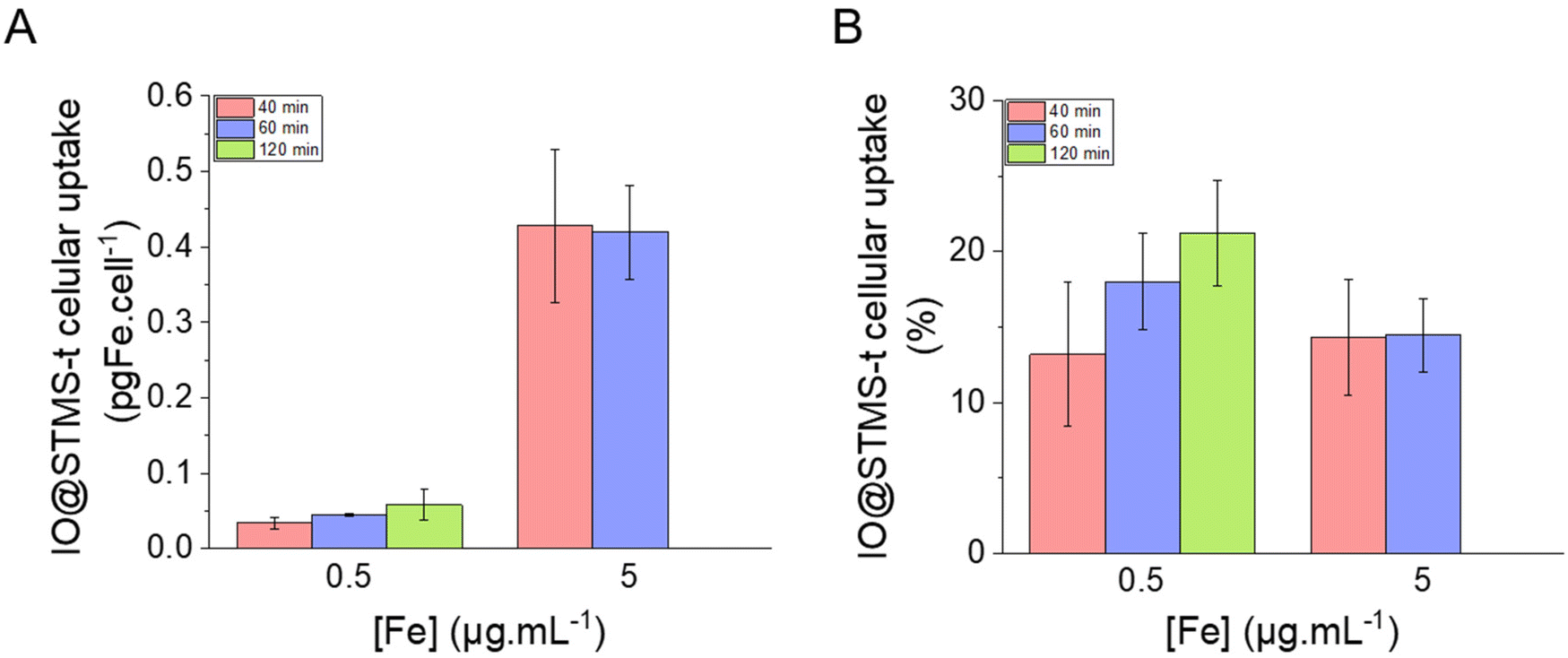 | ||
| Fig. 13 IO@STMS-t NP cellular uptake in (A) pgFe per cell and in (B) percentage of incubated iron. Statistical analysis gave no significant difference between the groups. | ||
TEM was also performed on the samples incubated at 5 μgFe mL−1 for 72 h in order to investigate the particles’ localization inside the cells. As can be seen in Fig. 14, the particles are localized in the lysosomes, meaning that we would have endo-lysosomal hyperthermia under AMF.
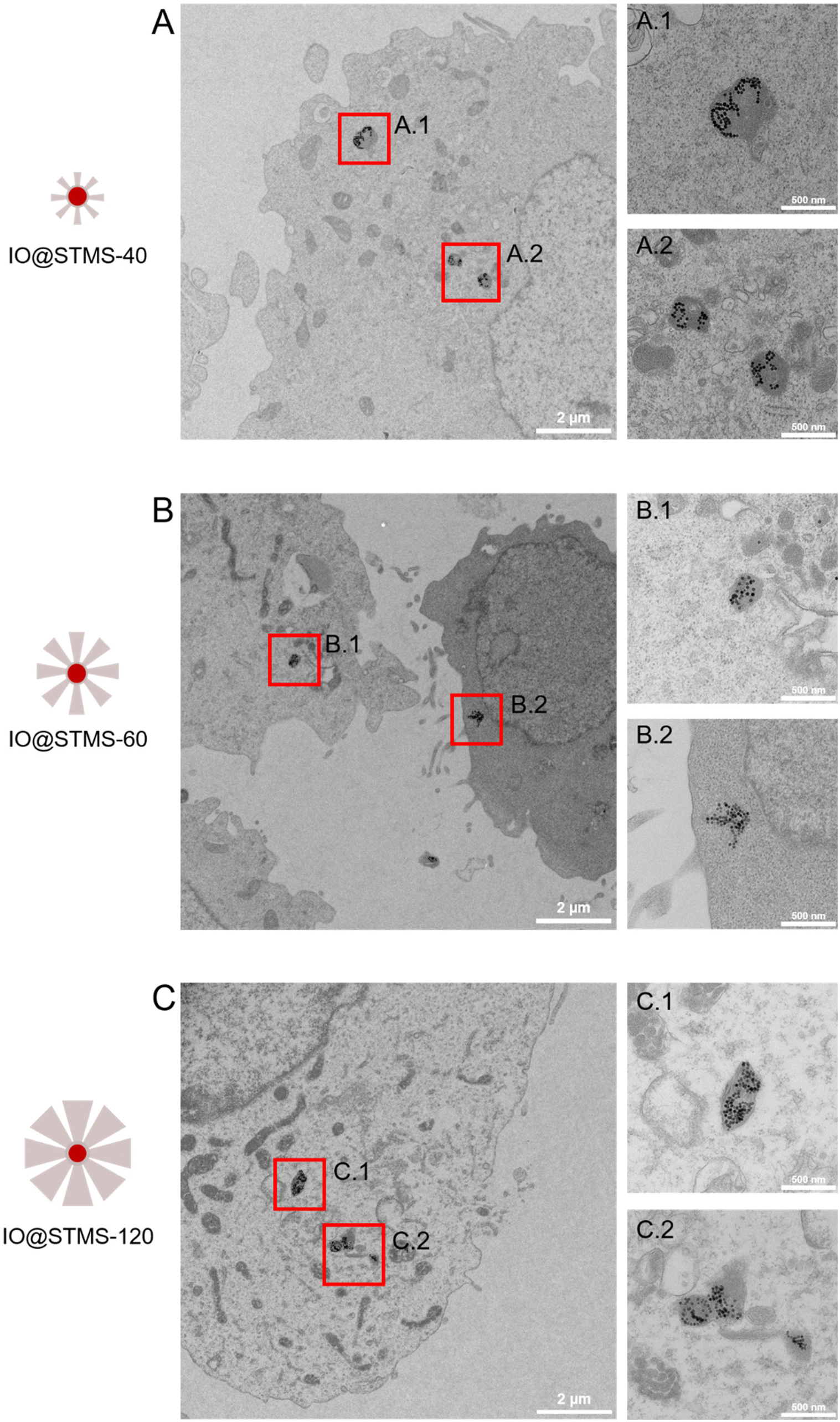 | ||
| Fig. 14 TEM images of cells incubated at 5 μgFe mL−1 for 72 h with (A) IO@STMS-40, (B) IO@STMS-60 and (C) IO@STMS-120 and respective magnifications of lysosomes in A.1, A.2; B.1, B.2 and C.1, C.2. | ||
Another interesting result obtained from this TEM intracellular imaging is that the silica shell appears to be importantly intracellularly degraded as only clustered IO NPs can be seen on the images presented in Fig. 14. However, it is important to note that silica shells could still be observed in very few imaged areas of IO@STMS-60 and IO@STMS-120. Indeed, as can be seen in Fig. S16A,† some IO NPs are not all clustered in the case of IO@STMS-60 and present a kind of corona that might be the silica shell degrading, being more transparent to the electron beam, leading thus to this poor contrast. However, the silica shell is clearly observable in the case of IO@STMS-120 as shown in Fig. S16B.†
The intracellular degradation of mesoporous silica NPs and also of iron oxide clusters@mesoporous silica NPs was previously reported to occur from some days to several weeks depending on the different parameters influencing the silica dissolution: NP concentration (silica limit solubility is reported in the range 140–160 μg mL−1 under standard physiological conditions), NP aggregation state, pore size, degree of silica condensation, etc.37,76
In our case, TEM intracellular imaging suggests that the degradation of the silica shell in the lysosomes is occurring rapidly (in three days) and is heterogeneous, which can come from the fact that the particle concentration is quite low, providing suitable low intra-lysosomal confinement and thus favouring silica shell dissolution.
The results of this labelling are presented in Fig. 15. As expected, the incubation of the cells with NPs only did not significantly increase cell death compared with the control, as well as the treatment with AMF only. Interestingly, AMF exposure increased the mortality of MIA Paca-2 cancer cells incubated with IO@STMS-40, especially at 5 μgFe mL−1 (Fig. 15A). Indeed, cell death was increased only from ca. 11.2 ± 1.5%, ca. 13.6 ± 2.2% and ca. 9.1 ± 1.2% for the control, NPs only and AMF only respectively to ca. 17.3 ± 0.6% for AMF+NPs when the cells were incubated at 0.5 μgFe mL−1 while it went up to ca. 28.8 ± 2.3% when the cells were incubated at 5 μgFe mL−1, which was determined to be significantly higher than the % of dead cells measured for the other treatments. Moreover, the dead cells are mainly labelled by AnnV, indicating an apoptosis-related cell death pathway induced by IO@STMS-40 upon MHT treatment. In contrast, IO@STMS-60 and IO@STMS-120 did not decrease the viability of the MIA Paca-2 cancer cells upon MHT treatment (Fig. 15B and C).
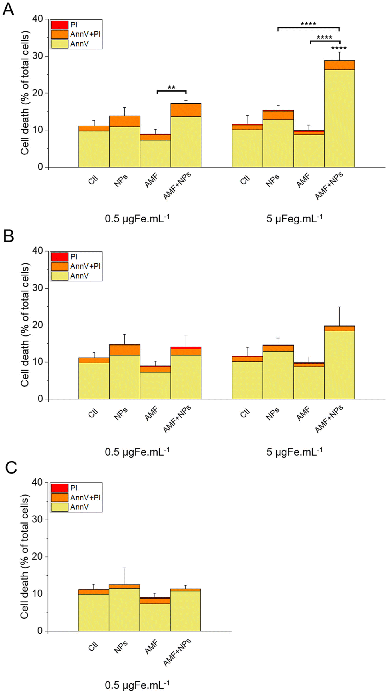 | ||
| Fig. 15 Cell death evaluated in the presence or absence of IO@STMS-t NPs with or without an AMF stimulus for (A) IO@STMS-40, (B) IO@STMS-60 and (C) IO@STMS-120. Error bars and statistical analysis are on the total percentage. | ||
Regarding these magnetothermal effects under AMF, we can only speculate that the improved cancer cell killing with the IO@STMS-40 sample as compared with the other samples is due to local heating effects at the surface of the IO NPs through the silica large-pore shell. Even if all of the AMF treatments on IO@STMS-t are made in macroscopically athermic conditions, we can hypothesize that the local temperature is higher when the silica shell is thinner and more opened. For instance, several teams showed a huge reduction in cancer cell viability using targeted magnetic nanoparticles without the need for a perceptible temperature rise.75,78,79 Furthermore, the total absence of a silica shell observed by the above intra-cellular TEM imaging in IO@STMS-40 as compared with IOSTMS-60 may also play a role in local related effects at the iron oxide surface (magnetothermal effect, ROS production, etc.) and thus might contribute to improving cytotoxicity.
Thus, these results tend to show that even if IO@STMS-40 has lower SAR values, at a slightly lower or similar amount of internalized iron, they are still the more promising nanoparticles for anti-cancer therapies using AMF.
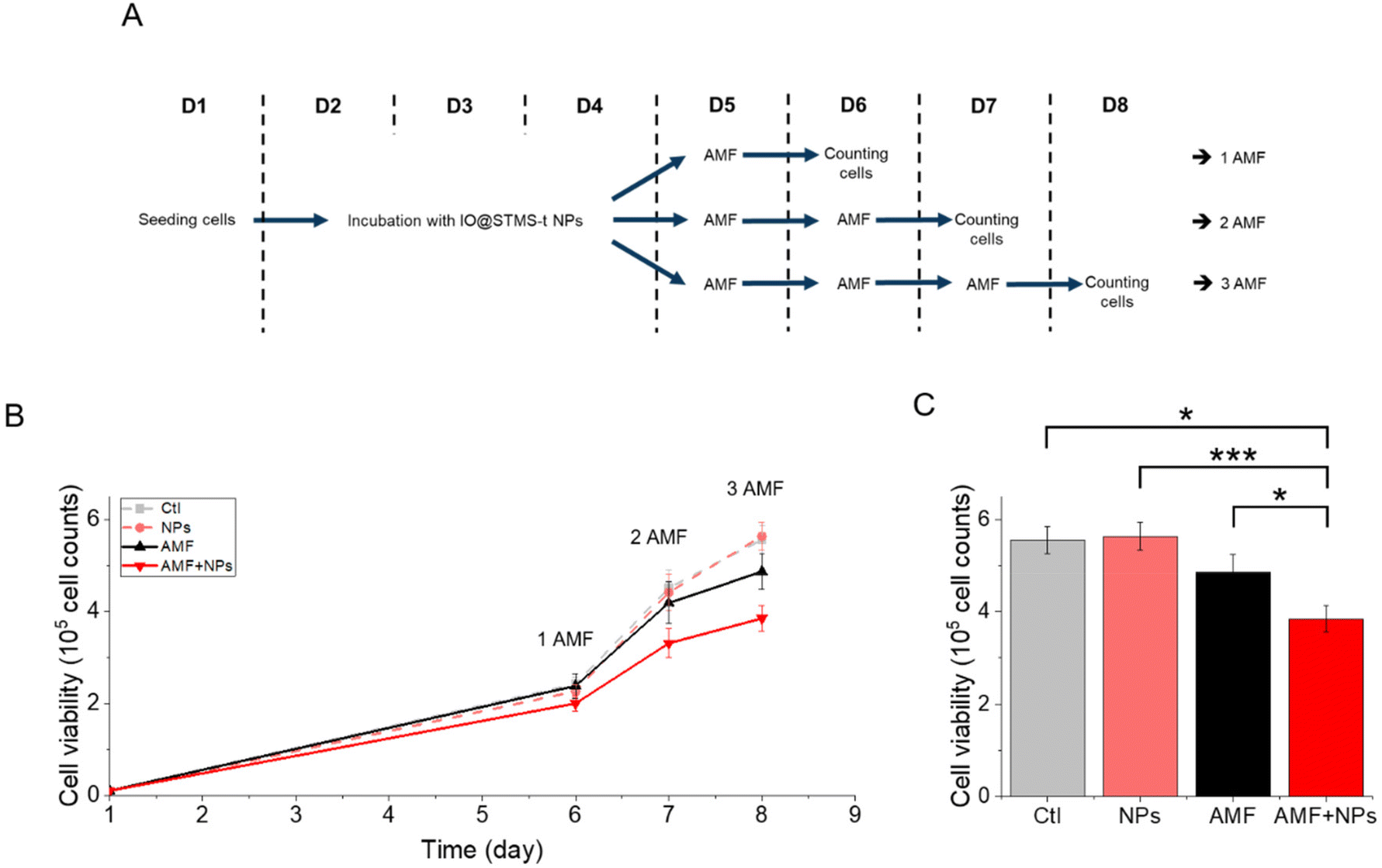
IO@STMS-40 NPs were thus used for a complementary experiment analysing cell proliferation. The cells were incubated or not with these NPs at 5 μgFe mL−1 for 72 h and exposed respectively one, two or three times to AMF (or not). A schematic representation of the protocol is given in Fig. 16A to better perceive it. The results, presented in Fig. 16B, show that cell proliferation is affected over time under exposure to AMF, and even more under exposure to AMF after being incubated with the NPs. Indeed, the number of cells dropped from 5.6 × 10⁵ ± 3.0 × 10⁴ without NPs or AMF, to 4.9 × 10⁵ ± 3.9 × 10⁴ after three exposures to AMF and to 3.8 × 10⁵ ± 2.8 × 10⁴ after incubation with NPs and three exposures to AMF, which has been determined to be significantly different, as shown in Fig. 16C. These results show again that IO@STMS-40 are promising NPs for anti-cancer therapies using AMF.
 | ||
| Fig. 16 (A) Schematic representation of the applied protocol for AMF. (B) Proliferation of MIA Paca-2 cancer cells along the treatment. Statistical analysis was done on the (C) proliferation at day 8. | ||
The application of an AMF to evaluate the potential of IO@STMS-t NPs for anti-cancer therapies makes sense as these particles are studied for magnetic hyperthermia treatment. However, it is also possible to use RMF in order to see if the NPs can induce cell death by mechanical forces and not only by the local increase of temperature. Similar experiments were then performed upon RMF application, with a frequency f of 1 Hz and an amplitude μ0*H of 40 mT (32 kA m−1). As can be seen in Fig. 17, only 5 μgFe mL−1 of IO@STMS-40 increased significantly cell death: ca. 22.6 ± 2.3% comparatively to ca. 11.2 ± 1.5% of the control cells. Moreover, dead cells are also mainly labelled by AnnV, indicating an apoptosis-related cell death pathway induced by IO@STMS-40 motion upon RMF application. Regarding these RMF results, we could also hypothesize that NP chaining is more probable with a thinner silica shell and may induce more efficient torque effects for IO@STMS-40 as compared with IO@STMS-60. However, these nanoparticles seemed less efficient under RMF compared with AMF: ca. 22.6 ± 2.3% versus ca. 28.8 ± 2.3% of cell death respectively after 5 μgFe mL−1 of IO@STMS-40 incubation.
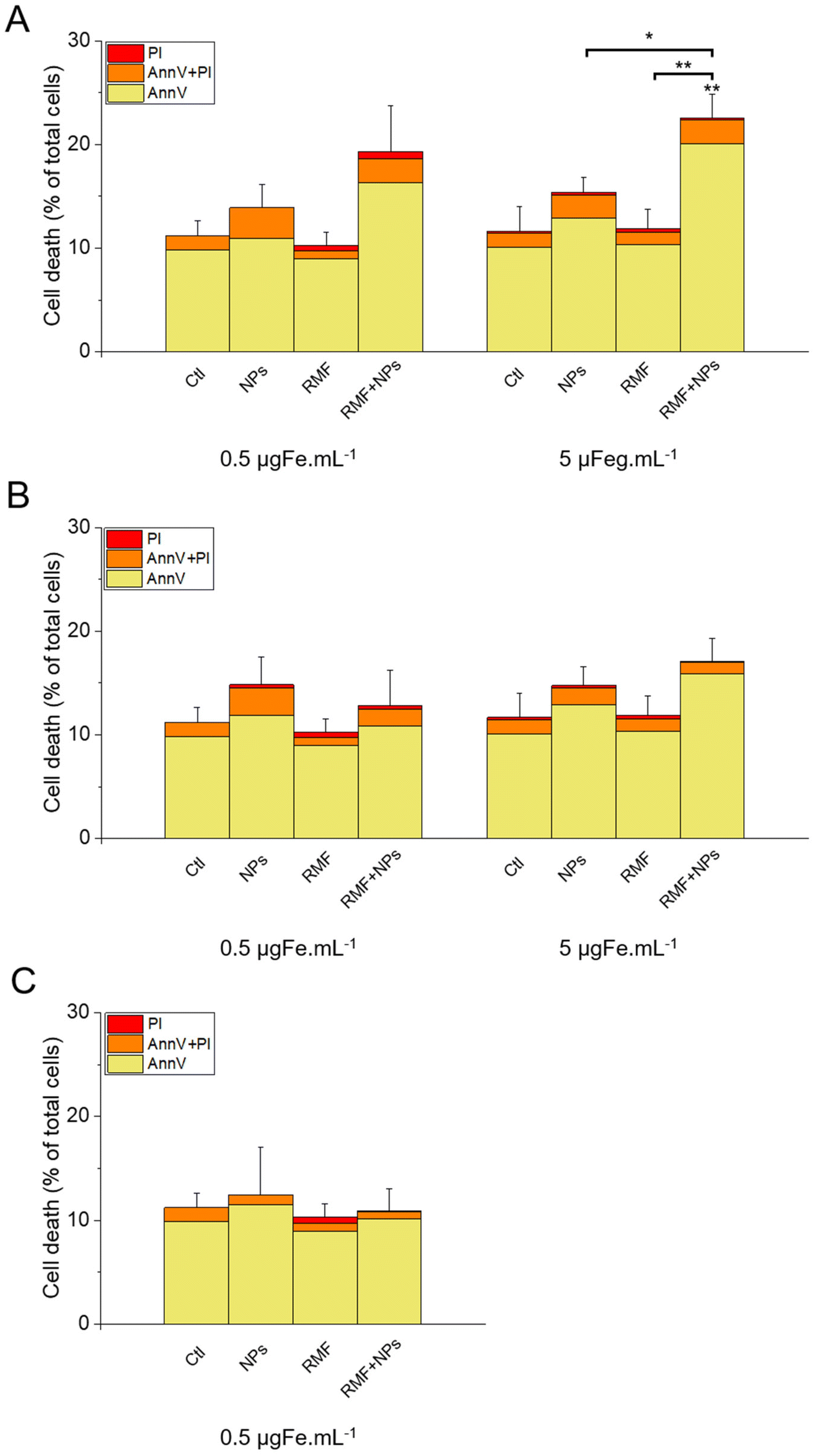 | ||
| Fig. 17 Cell death evaluated in the presence or absence of IO@STMS-t NPs with or without an RMF stimulus for (A) IO@STMS-40, (B) IO@STMS-60 and (C) IO@STMS-120. Error bars and statistical analysis are on the total percentage. | ||
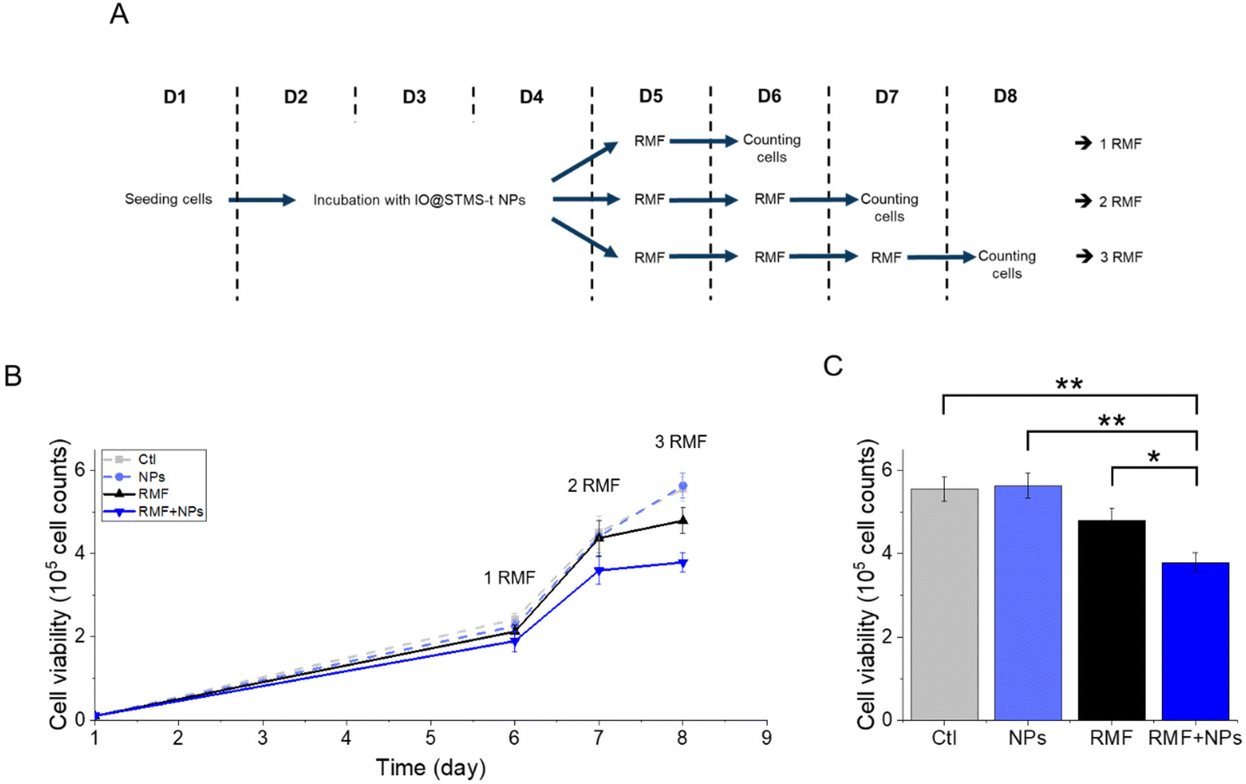
Regarding the multiple application of RMF with or without IO@STMS-40 NPs, the results presented in Fig. 18 show a significant impact of the multiple exposure to RMF and to RMF with NPs. Indeed, the number of cells dropped from 5.6 × 10⁵ ± 3.0 × 10⁴ without NPs or RMF, to 4.8 × 10⁵ ± 3.1 × 10⁴ after three exposures to RMF and to 3.8 × 10⁵ ± 2.3 × 10⁴ after incubation with NPs and three exposures to RMF, showing one more time the great potential of IO@STMS-40 NPs for anti-cancer therapy under RMF.
 | ||
| Fig. 18 (A) Schematic representation of the applied protocol for RMF. (B) Proliferation of MIA Paca-2 cancer cells along the treatment. Statistical analysis was done on the (C) proliferation at day 8 after three exposures to RMF or no exposure. | ||
Altogether, these results show that IO@STMS-40 are the best candidates between the IO@STMS-t NPs for anti-cancer therapies, whether using an AMF or RMF stimulus. The cell death may represent a low value (∼23–29% of total cells), which can be disappointing regarding the quite high SAR and ILP values determined in the previous section. However, multiple exposures to AMF or RMF significantly reduced the cell proliferation, showing its potential for such application.
In addition, we have to keep in mind that the IO@STMS-t NPs were used here without any polymer coating. Such a coating may enhance their internalization and decrease cytotoxicity which would allow an increase in the concentration of nanoparticles, and thus should increase their anti-cancer efficiency.
As a perspective, there are various strategies of polymer coatings around mesoporous silica that may be used to enhance cancer cell uptake. Among them, we can cite polycation surface modifications like the non-covalently adsorbed polyethyleneimine coatings ensuring a strong interaction with the negatively charged cell membrane, and yielding a high cellular uptake.80 We can cite also the covalently bound polyarginine acting as a cancer cell-penetrating cationic polypeptide.81 Another surface modification strategy is the covalent conjugation of hyaluronic acid, a negatively charged polyelectrolyte, which ensures efficient cell internalization through targeting the CD44 receptor overexpressed in cancer cells.82
IV. Conclusion
In this work, we have addressed the fine tuning of the STMS shell growth around an IO NP core by simply playing on the sol–gel time of the synthesis. The control of the STMS shell growth was evidenced as well by time-lapse TEM imaging and by in situ LPTEM, which were found to be very complementary. The evolution of the pore structure was also deeply investigated by nitrogen adsorption–desorption measurements (BET, BJH and Horvath–Kawazoe methods) and we could show that increasing the shell thickness resulted in a decrease of the specific surface area, pore volume and pore size. This new synthesis approach based on a very simple procedure allows the preparation of a range of new IO@STMS core–shell NPs with tunable shell thickness and pore structure. Furthermore, all of these IO@STMS-t (with t being the growth time) were shown to have overall a good colloidal stability.The impact of the STMS shell thickness on the MRI and hyperthermia properties of the IO NPs core was then studied. First, regarding MRI applications, we showed that STMS shell growth had no detrimental impact on the T2-weighted MRI relaxivities, making these IO@STMS-t NPs very good T2 contrast agents with relaxivity values in the range of 320–377 mM−1 s−1. Regarding the evolution of the T1-weighted MRI relaxivities, which decreased strongly with silica shell thickness, these allow confirmation of the densification of the silica walls with the increase of growth time, limiting water accessibility. Regarding the hyperthermia properties of the IO@STMS-t NPs, we could see a slight decrease of the SAR value determined under an AMF stimulus and no clear impact on the SAR value determined under an NIR light stimulus, indicating that the stellate porous silica shell provides a low insulating property with silica shell growth. Overall, it does not affect the heat dissipation from the core to the surrounding media, making all these core–shell IO@STMS-t NPs efficient heating agents under AMF or NIR light irradiation stimulation.
Finally, several in vitro experiments using the pancreatic cancer cell line MIA Paca-2 were performed in order to evaluate the potential use of these IO@STMS-t NPs for anti-cancer applications. We were able to show that ∼14% of the incubated particles were internalised by the cells and that the application of AMF or RMF improved the anti-cancer efficiency of IO@STMS-40.
This study showed the great interest from adding the STMS shell around the IO NP core as it notably stabilises the particles and does not hinder their interesting properties, namely MRI, MHT and PHT. In addition, the in vitro experiments showed the interest for using such core–shell NPs to improve anti-cancer treatment by using external magnetic fields. Such systems could then be envisioned for bimodal anti-cancer applications, with the combination of local hyperthermia with the thermally-induced controlled delivery of therapeutic molecules of a higher size than synthesised ones, such as protein, DNA or RNA. However, as such biomolecules are quite sensitive to thermal denaturation, evaluation of the local temperature at the surface of the IO@STMS NPs would also be future studies to investigate.
Data availability
Data for this article are available at Recherche.Data.Gouv repository at the https://doi.org/10.57745/SVCWSI.Conflicts of interest
There are no conflicts of interest to declare.Acknowledgements
D. M. and J. B. (for PhD and postdoc supports) acknowledge the Agence Nationale de la Recherche (grant ANR-19-CE09-0004—Corelmag) and the Materials Institute Carnot Alsace (Inter-Carnot project, Nanobiocities). The spectroscopy and the transmission electronic microscopy platforms of the IPCMS are acknowledged for technical support.References
- K. Y. Choi, G. Liu, S. Lee and X. Chen, Theranostic Nanoplatforms for Simultaneous Cancer Imaging and Therapy: Current Approaches and Future Perspectives, Nanoscale, 2012, 4(2), 330–342, 10.1039/C1NR11277E.
- S. M. Janib, A. S. Moses and J. A. MacKay, Imaging and Drug Delivery Using Theranostic Nanoparticles, Adv. Drug Delivery Rev., 2010, 62(11), 1052–1063, DOI:10.1016/j.addr.2010.08.004.
- C. Blanco-Andujar, A. Walter, G. Cotin, C. Bordeianu, D. Mertz, D. Felder-Flesch and S. Begin-Colin, Design of Iron Oxide-Based Nanoparticles for MRI and Magnetic Hyperthermia, Nanomedicine, 2016, 11(14), 1889–1910, DOI:10.2217/nnm-2016-5001.
- S. Laurent, D. Forge, M. Port, A. Roch, C. Robic, L. Vander Elst and R. N. Muller, Magnetic Iron Oxide Nanoparticles: Synthesis, Stabilization, Vectorization, Physicochemical Characterizations, and Biological Applications, Chem. Rev., 2008, 108(6), 2064–2110, DOI:10.1021/cr068445e.
- H. B. Na, I. C. Song and T. Hyeon, Inorganic Nanoparticles for MRI Contrast Agents, Adv. Mater., 2009, 21(21), 2133–2148, DOI:10.1002/adma.200802366.
- R. Hachani, M. Lowdell, M. Birchall, A. Hervault, D. Mertz, S. Begin-Colin and N. T. K. Thanh, Polyol Synthesis, Functionalisation, and Biocompatibility Studies of Superparamagnetic Iron Oxide Nanoparticles as Potential MRI Contrast Agents, Nanoscale, 2016, 8(6), 3278–3287, 10.1039/C5NR03867G.
- B. Thiesen and A. Jordan, Clinical Applications of Magnetic Nanoparticles for Hyperthermia, Int. J. Hyperthermia, 2008, 24(6), 467–474, DOI:10.1080/02656730802104757.
- K. Maier-Hauff, F. Ulrich, D. Nestler, H. Niehoff, P. Wust, B. Thiesen, H. Orawa, V. Budach and A. Jordan, Efficacy and Safety of Intratumoral Thermotherapy Using Magnetic Iron-Oxide Nanoparticles Combined with External Beam Radiotherapy on Patients with Recurrent Glioblastoma Multiforme, J. Neurooncol., 2011, 103(2), 317–324, DOI:10.1007/s11060-010-0389-0.
- K. Maier-Hauff, R. Rothe, R. Scholz, U. Gneveckow, P. Wust, B. Thiesen, A. Feussner, A. von Deimling, N. Waldoefner, R. Felix and A. Jordan, Intracranial Thermotherapy Using Magnetic Nanoparticles Combined with External Beam Radiotherapy: Results of a Feasibility Study on Patients with Glioblastoma Multiforme, J. Neurooncol., 2007, 81(1), 53–60, DOI:10.1007/s11060-006-9195-0.
- B. Freis, G. Cotin, F. Perton, D. Mertz, S. Boutry, S. Laurent and S. Begin-Colin, The Size, Shape, and Composition Design of Iron Oxide Nanoparticles to Combine, MRI, Magnetic Hyperthermia, and Photothermia, in Magnetic Nanoparticles in Human Health and Medicine, ed. C. Caizer and M. Rai, Wiley, 2021, pp. 380–429. DOI:10.1002/9781119754725.ch17.
- J. Estelrich and M. Busquets, Iron Oxide Nanoparticles in Photothermal Therapy, Molecules, 2018, 23(7), 1567, DOI:10.3390/molecules23071567.
- S. Shen, S. Wang, R. Zheng, X. Zhu, X. Jiang, D. Fu and W. Yang, Magnetic Nanoparticle Clusters for Photothermal Therapy with Near-Infrared Irradiation, Biomaterials, 2015, 39, 67–74, DOI:10.1016/j.biomaterials.2014.10.064.
- S. Cabana, A. Curcio, A. Michel, C. Wilhelm and A. Abou-Hassan, Iron Oxide Mediated Photothermal Therapy in the Second Biological Window: A Comparative Study between Magnetite/Maghemite Nanospheres and Nanoflowers, Nanomaterials, 2020, 10(8), 1548, DOI:10.3390/nano10081548.
- T.-J. Yu, P.-H. Li, T.-W. Tseng and Y.-C. Chen, Multifunctional Fe3O4 /Alumina Core/Shell MNPs as Photothermal Agents for Targeted Hyperthermia of Nosocomial and Antibiotic-Resistant Bacteria, Nanomedicine, 2011, 6(8), 1353–1363, DOI:10.2217/nnm.11.34.
- M. Mahmoudi, I. Lynch, M. R. Ejtehadi, M. P. Monopoli, F. B. Bombelli and S. Laurent, Protein–Nanoparticle Interactions: Opportunities and Challenges, Chem. Rev., 2011, 111(9), 5610–5637, DOI:10.1021/cr100440g.
- G. Cotin, S. Piant, D. Mertz, D. Felder-Flesch and S. Begin-Colin, Iron Oxide Nanoparticles for Biomedical Applications: Synthesis, Functionalization, and Application, in Iron Oxide Nanoparticles for Biomedical Applications: Synthesis, Functionalization, and Application, Elsevier, 2018, pp. 43–88. DOI:10.1016/B978-0-08-101925-2.00002-4.
- M. Manzano and M. Vallet-Regí, Mesoporous Silica Nanoparticles for Drug Delivery, Adv. Funct. Mater., 2020, 30(2), 1902634, DOI:10.1002/adfm.201902634.
- F. Tang, L. Li and D. Chen, Mesoporous Silica Nanoparticles: Synthesis, Biocompatibility and Drug Delivery, Adv. Mater., 2012, 24(12), 1504–1534, DOI:10.1002/adma.201104763.
- C. Argyo, V. Weiss, C. Bräuchle and T. Bein, Multifunctional Mesoporous Silica Nanoparticles as a Universal Platform for Drug Delivery, Chem. Mater., 2014, 26(1), 435–451, DOI:10.1021/cm402592t.
- J. Kim, H. S. Kim, N. Lee, T. Kim, H. Kim, T. Yu, I. C. Song, W. K. Moon and T. Hyeon, Multifunctional Uniform Nanoparticles Composed of a Magnetite Nanocrystal Core and a Mesoporous Silica Shell for Magnetic Resonance and Fluorescence Imaging and for Drug Delivery, Angew. Chem., Int. Ed., 2008, 47(44), 8438–8441, DOI:10.1002/anie.200802469.
- J. Liu, C. Detrembleur, M.-C. De Pauw-Gillet, S. Mornet, L. V. Elst, S. Laurent, C. Jérôme and E. Duguet, Heat-Triggered Drug Release Systems Based on Mesoporous Silica Nanoparticles Filled with a Maghemite Core and Phase-Change Molecules as Gatekeepers, J. Mater. Chem. B, 2014, 2(1), 59–70, 10.1039/C3TB21229G.
- N.Ž Knežević, I. I. Slowing and V. S.-Y. Lin, Tuning the Release of Anticancer Drugs from Magnetic Iron Oxide/Mesoporous Silica Core/Shell Nanoparticles, ChemPlusChem, 2012, 77(1), 48–55, DOI:10.1002/cplu.201100026.
- M. Asgari, M. Soleymani, T. Miri and A. Barati, A Robust Method for Fabrication of Monodisperse Magnetic Mesoporous Silica Nanoparticles with Core-Shell Structure as Anticancer Drug Carriers, J. Mol. Liq., 2019, 292, 111367, DOI:10.1016/j.molliq.2019.111367.
- P. Yang, S. Gai and J. Lin, Functionalized Mesoporous Silica Materials for Controlled Drug Delivery, Chem. Soc. Rev., 2012, 41(9), 3679, 10.1039/c2cs15308d.
- Y. Deng, D. Qi, C. Deng, X. Zhang and D. Zhao, Superparamagnetic High-Magnetization Microspheres with an Fe3O4 @SiO2 Core and Perpendicularly Aligned Mesoporous SiO2 Shell for Removal of Microcystins, J. Am. Chem. Soc., 2008, 130(1), 28–29, DOI:10.1021/ja0777584.
- J. Kim, J. E. Lee, J. Lee, J. H. Yu, B. C. Kim, K. An, Y. Hwang, C.-H. Shin, J.-G. Park, J. Kim and T. Hyeon, Magnetic Fluorescent Delivery Vehicle Using Uniform Mesoporous Silica Spheres Embedded with Monodisperse Magnetic and Semiconductor Nanocrystals, J. Am. Chem. Soc., 2006, 128(3), 688–689, DOI:10.1021/ja0565875.
- H. Fan, K. Yang, D. M. Boye, T. Sigmon, K. J. Malloy, H. Xu, G. P. López and C. J. Brinker, Self-Assembly of Ordered, Robust, Three-Dimensional Gold Nanocrystal/Silica Arrays, Science, 2004, 304(5670), 567–571, DOI:10.1126/science.1095140.
- H. Fan, E. W. Leve, C. Scullin, J. Gabaldon, D. Tallant, S. Bunge, T. Boyle, M. C. Wilson and C. J. Brinker, Surfactant-Assisted Synthesis of Water-Soluble and Biocompatible Semiconductor Quantum Dot Micelles, Nano Lett., 2005, 5(4), 645–648, DOI:10.1021/nl050017l.
- H. Fan, Z. Chen, C. J. Brinker, J. Clawson and T. Alam, Synthesis of Organo-Silane Functionalized Nanocrystal Micelles and Their Self-Assembly, J. Am. Chem. Soc., 2005, 127(40), 13746–13747, DOI:10.1021/ja053795o.
- H. Fan, A. Wright, J. Gabaldon, A. Rodriguez, C. J. Brinker and Y.-B. Jiang, Three-Dimensionally Ordered Gold Nanocrystal/Silica Superlattice Thin Films Synthesized via Sol–Gel Self-Assembly, Adv. Funct. Mater., 2006, 16(7), 891–895, DOI:10.1002/adfm.200500603.
- F. Ye, S. Laurent, A. Fornara, L. Astolfi, J. Qin, A. Roch, A. Martini, M. S. Toprak, R. N. Muller and M. Muhammed, Uniform Mesoporous Silica Coated Iron Oxide Nanoparticles as a Highly Efficient, Nontoxic MRI T2 Contrast Agent with Tunable Proton Relaxivities: Fe3O4@mSiO2 with tunable relaxivities, Contrast Media Mol. Imaging, 2012, 7(5), 460–468, DOI:10.1002/cmmi.1473.
- J. Bizeau and D. Mertz, Design and Applications of Protein Delivery Systems in Nanomedicine and Tissue Engineering, Adv. Colloid Interface Sci., 2021, 287, 102334, DOI:10.1016/j.cis.2020.102334.
- J. Zhang, X. Li, J. M. Rosenholm and H. Gu, Synthesis and Characterization of Pore Size-Tunable Magnetic Mesoporous Silica Nanoparticles, J. Colloid Interface Sci., 2011, 361(1), 16–24, DOI:10.1016/j.jcis.2011.05.038.
- Z. Sun, X. Zhou, W. Luo, Q. Yue, Y. Zhang, X. Cheng, W. Li, B. Kong, Y. Deng and D. Zhao, Interfacial Engineering of Magnetic Particles with Porous Shells: Towards Magnetic Core – Porous Shell Microparticles, Nano Today, 2016, 11(4), 464–482, DOI:10.1016/j.nantod.2016.07.003.
- L. Xiong, J. Bi, Y. Tang and S. Qiao, Magnetic Core–Shell Silica Nanoparticles with Large Radial Mesopores for SiRNA Delivery, Small, 2016, 12(34), 4735–4742, DOI:10.1002/smll.201600531.
- S. Nemec and S. Kralj, A Versatile Interfacial Coassembly Method for Fabrication of Tunable Silica Shells with Radially Aligned Dual Mesopores on Diverse Magnetic Core Nanoparticles, ACS Appl. Mater. Interfaces, 2021, 13(1), 1883–1894, DOI:10.1021/acsami.0c17863.
- R. Fiedler, G. Sivakumaran, J. Mallén and M. Lindén, Superparamagnetic Core–Mesoporous Silica Shell Nanoparticles with Tunable Extra- and Intracellular Dissolution Rates, Chem. Mater., 2024, 36(6), 2790–2798, DOI:10.1021/acs.chemmater.3c02986.
- R. Fiedler, B. Beizinger, P. Walther and M. Lindén, Synthesis of Highly Monodisperse Superparamagnetic Iron Oxide Core@mesoporous Silica Shell Particles with Independently Tunable Size, and Porosity, Microporous Mesoporous Mater., 2022, 340, 112027, DOI:10.1016/j.micromeso.2022.112027.
- K. Zhang, L.-L. Xu, J.-G. Jiang, N. Calin, K.-F. Lam, S.-J. Zhang, H.-H. Wu, G.-D. Wu, B. Albela, L. Bonneviot and P. Wu, Facile Large-Scale Synthesis of Monodisperse Mesoporous Silica Nanospheres with Tunable Pore Structure, J. Am. Chem. Soc., 2013, 135(7), 2427–2430, DOI:10.1021/ja3116873.
- F. Perton, S. Harlepp, G. Follain, K. Parkhomenko, J. G. Goetz, S. Bégin-Colin and D. Mertz, Wrapped Stellate Silica Nanocomposites as Biocompatible Luminescent Nanoplatforms Assessed in Vivo, J. Colloid Interface Sci., 2019, 542, 469–482, DOI:10.1016/j.jcis.2019.01.098.
- P. Duenas-Ramirez, C. Bertagnolli, R. Müller, K. Sartori, A. Boos, M. Elhabiri, S. Bégin-Colin and D. Mertz, Highly Chelating Stellate Mesoporous Silica Nanoparticles for Specific Iron Removal from Biological Media, J. Colloid Interface Sci., 2020, 579, 140–151, DOI:10.1016/j.jcis.2020.06.013.
- J. Bizeau, A. Adam, C. Nadal, G. Francius, D. Siniscalco, M. Pauly, S. Bégin-Colin and D. Mertz, Protein Sustained Release from Isobutyramide-Grafted Stellate Mesoporous Silica Nanoparticles, Int. J. Pharm.: X, 2022, 4, 100130, DOI:10.1016/j.ijpx.2022.100130.
- J. Bizeau, A. Adam, S. Bégin and D. Mertz, Serum Albumin Antifouling Effects of Hydroxypropyl–cellulose and Pluronic F127 Adsorbed on Isobutyramide–grafted Stellate Silica Nanoparticles, Eur. J. Inorg. Chem., 2021, 2021, 4799–4805, DOI:10.1002/ejic.202100678.
- A. Adam, K. Parkhomenko, P. Duenas-Ramirez, C. Nadal, G. Cotin, P.-E. Zorn, P. Choquet, S. Bégin-Colin and D. Mertz, Orienting the Pore Morphology of Core-Shell Magnetic Mesoporous Silica with the Sol-Gel Temperature. Influence on MRI and Magnetic Hyperthermia Properties, Molecules, 2021, 26(4), 971, DOI:10.3390/molecules26040971.
- A. Adam, S. Harlepp, F. Ghilini, G. Cotin, B. Freis, J. Goetz, S. Bégin, M. Tasso and D. Mertz, Core-Shell Iron Oxide@stellate Mesoporous Silica for Combined near-Infrared Photothermia and Drug Delivery: Influence of PH and Surface Chemistry, Colloids Surf., A, 2022, 640, 128407, DOI:10.1016/j.colsurfa.2022.128407.
- F. Perton, M. Tasso, G. A. Muñoz Medina, M. Ménard, C. Blanco-Andujar, E. Portiansky, M. B. F. van Raap, D. Bégin, F. Meyer, S. Begin-Colin and D. Mertz, Fluorescent and Magnetic Stellate Mesoporous Silica for Bimodal Imaging and Magnetic Hyperthermia, Appl. Mater. Today, 2019, 16, 301–314, DOI:10.1016/j.apmt.2019.06.006.
- G. Cotin, F. Perton, C. Petit, S. Sall, C. Kiefer, V. Begin, B. Pichon, C. Lefevre, D. Mertz, J.-M. Greneche and S. Begin-Colin, Harnessing Composition of Iron Oxide Nanoparticle: Impact of Solvent-Mediated Ligand–Ligand Interaction and Competition between Oxidation and Growth Kinetics, Chem. Mater., 2020, 32(21), 9245–9259, DOI:10.1021/acs.chemmater.0c03041.
- G. Cotin, C. Kiefer, F. Perton, D. Ihiawakrim, C. Blanco-Andujar, S. Moldovan, C. Lefevre, O. Ersen, B. Pichon, D. Mertz and S. Bégin-Colin, Unravelling the Thermal Decomposition Parameters for The Synthesis of Anisotropic Iron Oxide Nanoparticles, Nanomaterials, 2018, 8(11), 881, DOI:10.3390/nano8110881.
- E. Garaio, J. M. Collantes, F. Plazaola, J. A. Garcia and I. Castellanos-Rubio, A Multifrequency Eletromagnetic Applicator with an Integrated AC Magnetometer for Magnetic Hyperthermia Experiments, Meas. Sci. Technol., 2014, 25(11), 115702, DOI:10.1088/0957-0233/25/11/115702.
- E. A. Périgo, G. Hemery, O. Sandre, D. Ortega, E. Garaio, F. Plazaola and F. J. Teran, Fundamentals and Advances in Magnetic Hyperthermia, Appl. Phys. Rev., 2015, 2(4), 041302, DOI:10.1063/1.4935688.
- W. Baaziz, B. P. Pichon, S. Fleutot, Y. Liu, C. Lefevre, J.-M. Greneche, M. Toumi, T. Mhiri and S. Begin-Colin, Magnetic Iron Oxide Nanoparticles: Reproducible Tuning of the Size and Nanosized-Dependent Composition, Defects, and Spin Canting, J. Phys. Chem. C, 2014, 118(7), 3795–3810, DOI:10.1021/jp411481p.
- G. Cotin, C. Blanco-Andujar, F. Perton, L. Asín, J. M. de la Fuente, W. Reichardt, D. Schaffner, D.-V. Ngyen, D. Mertz, C. Kiefer, F. Meyer, S. Spassov, O. Ersen, M. Chatzidakis, G. A. Botton, C. Hénoumont, S. Laurent, J.-M. Greneche, F. J. Teran, D. Ortega, D. Felder-Flesch and S. Begin-Colin, Unveiling the Role of Surface, Size, Shape and Defects of Iron Oxide Nanoparticles for Theranostic Applications, Nanoscale, 2021, 13(34), 14552–14571, 10.1039/D1NR03335B.
- G. M. L. Dalmônico, D. Ihiawakrim, N. Ortiz, A. G. Barreto Junior, C. F. Curitiba Marcellos, M. Farina, O. Ersen and A. L. Rossi, Live Visualization of the Nucleation and Growth of Needle-Like Hydroxyapatite Crystals in Solution by In Situ TEM, Cryst. Growth Des., 2022, 22(8), 4828–4837, DOI:10.1021/acs.cgd.2c00296.
- V. Ramnarain, T. Georges, N. Ortiz Peña, D. Ihiawakrim, M. Longuinho, H. Bulou, C. Gervais, C. Sanchez, T. Azaïs and O. Ersen, Monitoring of CaCO3 Nanoscale Structuration through Real-Time Liquid Phase Transmission Electron Microscopy and Hyperpolarized NMR, J. Am. Chem. Soc., 2022, 144(33), 15236–15251, DOI:10.1021/jacs.2c05731.
- C. Sidhoum, D. Constantin, D. Ihiawakrim, M. Lenertz, T. Bizien, C. Sanchez and O. Ersen, Shedding Light on the Birth of Hybrid Perovskites: A Correlative Study by In Situ Electron Microscopy and Synchrotron-Based X-Ray Scattering, Chem. Mater., 2023, 35(19), 7943–7956, DOI:10.1021/acs.chemmater.3c01167.
- Z. A. Alothman, A Review: Fundamental Aspects of Silicate Mesoporous Materials, Materials, 2012, 5(12), 2874–2902, DOI:10.3390/ma5122874.
- X. Kesse, A. Adam, S. Begin-Colin, D. Mertz, E. Larquet, T. Gacoin, I. Maurin, C. Vichery and J.-M. Nedelec, Elaboration of Superparamagnetic and Bioactive Multicore–Shell Nanoparticles (γ-Fe 2 O 3 @SiO2-CaO): A Promising Material for Bone Cancer Treatment, ACS Appl. Mater. Interfaces, 2020, 12(42), 47820–47830, DOI:10.1021/acsami.0c12769.
- J. S. Weinstein, C. G. Varallyay, E. Dosa, S. Gahramanov, B. Hamilton, W. D. Rooney, L. L. Muldoon and E. A. Neuwelt, Superparamagnetic Iron Oxide Nanoparticles: Diagnostic Magnetic Resonance Imaging and Potential Therapeutic Applications in Neurooncology and Central Nervous System Inflammatory Pathologies, a Review, J. Cereb. Blood Flow Metab., 2010, 30(1), 15–35, DOI:10.1038/jcbfm.2009.192.
- B. Basly, D. Felder-Flesch, P. Perriat, C. Billotey, J. Taleb, G. Pourroy and S. Begin-Colin, Dendronized Iron Oxide Nanoparticles as Contrast Agents for MRI, Chem. Commun., 2010, 46(6), 985–987, 10.1039/B920348F.
- A. Walter, C. Billotey, A. Garofalo, C. Ulhaq-Bouillet, C. Lefèvre, J. Taleb, S. Laurent, L. Vander Elst, R. N. Muller, L. Lartigue, F. Gazeau, D. Felder-Flesch and S. Begin-Colin, Mastering the Shape and Composition of Dendronized Iron Oxide Nanoparticles To Tailor Magnetic Resonance Imaging and Hyperthermia, Chem. Mater., 2014, 26(18), 5252–5264, DOI:10.1021/cm5019025.
- W. Wang, F. Li, S. Li, Y. Hu, M. Xu, Y. Zhang, M. I. Khan, S. Wang, M. Wu, W. Ding and B. Qiu, M2 Macrophage-Targeted Iron Oxide Nanoparticles for Magnetic Resonance Image-Guided Magnetic Hyperthermia Therapy, J. Mater. Sci. Technol., 2021, 81, 77–87, DOI:10.1016/j.jmst.2020.11.058.
- N. Mille, D. De Masi, S. Faure, J. M. Asensio, B. Chaudret and J. Carrey, Probing Dynamics of Nanoparticle Chains Formation during Magnetic Hyperthermia Using Time-Dependent High-Frequency Hysteresis Loops, Appl. Phys. Lett., 2021, 119(2), 022407, DOI:10.1063/5.0056449.
- C. Martinez-Boubeta, K. Simeonidis, A. Makridis, M. Angelakeris, O. Iglesias, P. Guardia, A. Cabot, L. Yedra, S. Estradé, F. Peiró, Z. Saghi, P. A. Midgley, I. Conde-Leborán, D. Serantes and D. Baldomir, Learning from Nature to Improve the Heat Generation of Iron-Oxide Nanoparticles for Magnetic Hyperthermia Applications, Sci. Rep., 2013, 3(1), 1652, DOI:10.1038/srep01652.
- D. Serantes, K. Simeonidis, M. Angelakeris, O. Chubykalo-Fesenko, M. Marciello, M. d. P. Morales, D. Baldomir and C. Martinez-Boubeta, Multiplying Magnetic Hyperthermia Response by Nanoparticle Assembling, J. Phys. Chem. C, 2014, 118(11), 5927–5934, DOI:10.1021/jp410717m.
- A. Adam, Nanoplateformes à Base de Silices Mésoporeuses Fonctionnelles Pour l'hyperthermie Magnétique, La Photothermie et La Délivrance d'agents Thérapeutiques, phdthesis, Université de Strasbourg, 2022. https://www.theses.fr/s269276 (accessed 2023-02-09) Search PubMed.
- J. Wells, D. Ortega, U. Steinhoff, S. Dutz, E. Garaio, O. Sandre, E. Natividad, M. M. Cruz, F. Brero, P. Southern, Q. A. Pankhurst, S. Spassov and RADIOMAG consortium, Challenges and Recommendations for Magnetic Hyperthermia Characterization Measurements, Int. J. Hyperthermia, 2021, 38(1), 447–460, DOI:10.1080/02656736.2021.1892837.
- R. E. Rosensweig, Heating Magnetic Fluid with Alternating Magnetic Field, J. Magn. Magn. Mater., 2002, 252, 370–374, DOI:10.1016/S0304-8853(02)00706-0.
- H. Gavilán, G. M. R. Rizzo, N. Silvestri, B. T. Mai and T. Pellegrino, Scale-up Approach for the Preparation of Magnetic Ferrite Nanocubes and Other Shapes with Benchmark Performance for Magnetic Hyperthermia Applications, Nat. Protoc., 2023, 18(3), 783–809, DOI:10.1038/s41596-022-00779-3.
- S. Stolik, J. Delgado, A. Pérez and L. Anasagasti, Measurement of the Penetration Depths of Red and near Infrared Light in Human “Ex Vivo” Tissues, J. Photochem. Photobiol., B, 2000, 57(2–3), 90–93, DOI:10.1016/S1011-1344(00)00082-8.
- T. A. Henderson and L. Morries, Near-Infrared Photonic Energy Penetration: Can Infrared Phototherapy Effectively Reach the Human Brain?, Neuropsychiatr. Dis. Treat., 2015, 2191, DOI:10.2147/NDT.S78182.
- A. Espinosa, R. Di Corato, J. Kolosnjaj-Tabi, P. Flaud, T. Pellegrino and C. Wilhelm, Duality of Iron Oxide Nanoparticles in Cancer Therapy: Amplification of Heating Efficiency by Magnetic Hyperthermia and Photothermal Bimodal Treatment, ACS Nano, 2016, 10(2), 2436–2446, DOI:10.1021/acsnano.5b07249.
- M. E. Sadat, M. Kaveh Baghbador, A. W. Dunn, H. P. Wagner, R. C. Ewing, J. Zhang, H. Xu, G. M. Pauletti, D. B. Mast and D. Shi, Photoluminescence and Photothermal Effect of Fe 3 O 4 Nanoparticles for Medical Imaging and Therapy, Appl. Phys. Lett., 2014, 105(9), 091903, DOI:10.1063/1.4895133.
- E. Bertuit, E. Benassai, G. Mériguet, J.-M. Greneche, B. Baptiste, S. Neveu, C. Wilhelm and A. Abou-Hassan, Structure–Property–Function Relationships of Iron Oxide Multicore Nanoflowers in Magnetic Hyperthermia and Photothermia, ACS Nano, 2022, 16(1), 271–284, DOI:10.1021/acsnano.1c06212.
- R. Hergt and S. Dutz, Magnetic Particle Hyperthermia—biophysical Limitations of a Visionary Tumour Therapy, J. Magn. Magn. Mater., 2007, 311(1), 187–192, DOI:10.1016/j.jmmm.2006.10.1156.
- P. Clerc, P. Jeanjean, N. Hallali, M. Gougeon, B. Pipy, J. Carrey, D. Fourmy and V. Gigoux, Targeted Magnetic Intra-Lysosomal Hyperthermia Produces Lysosomal Reactive Oxygen Species and Causes Caspase-1 Dependent Cell Death, J. Controlled Release, 2018, 270, 120–134, DOI:10.1016/j.jconrel.2017.11.050.
- J. G. Croissant, Y. Fatieiev and N. M. Khashab, Degradability and Clearance of Silicon, Organosilica, Silsesquioxane, Silica Mixed Oxide, and Mesoporous Silica Nanoparticles, Adv. Mater., 2017, 29(9), 1604634, DOI:10.1002/adma.201604634.
- E. Brauchle, S. Thude, S. Y. Brucker and K. Schenke-Layland, Cell Death Stages in Single Apoptotic and Necrotic Cells Monitored by Raman Microspectroscopy, Sci. Rep., 2014, 4(1), 1–9, DOI:10.1038/srep04698.
- M. Creixell, A. C. Bohórquez, M. Torres-Lugo and C. Rinaldi, EGFR-Targeted Magnetic Nanoparticle Heaters Kill Cancer Cells without a Perceptible Temperature Rise, ACS Nano, 2011, 5(9), 7124–7129, DOI:10.1021/nn201822b.
- C. Sanchez, D. El Hajj Diab, V. Connord, P. Clerc, E. Meunier, B. Pipy, B. Payré, R. P. Tan, M. Gougeon, J. Carrey, V. Gigoux and D. Fourmy, Targeting a G-Protein-Coupled Receptor Overexpressed in Endocrine Tumors by Magnetic Nanoparticles To Induce Cell Death, ACS Nano, 2014, 8(2), 1350–1363, DOI:10.1021/nn404954s.
- T. Xia, M. Kovochich, M. Liong, H. Meng, S. Kabehie, S. George, J. I. Zink and A. E. Nel, Polyethyleneimine Coating Enhances the Cellular Uptake of Mesoporous Silica Nanoparticles and Allows Safe Delivery of SiRNA and DNA Constructs, ACS Nano, 2009, 3(10), 3273–3286, DOI:10.1021/nn900918w.
- M. Kar, N. Tiwari, M. Tiwari, M. Lahiri and S. S. Gupta, Poly–L–Arginine Grafted Silica Mesoporous Nanoparticles for Enhanced Cellular Uptake and Their Application in DNA Delivery and Controlled Drug Release, Part. Part. Syst. Charact., 2013, 30(2), 166–179, DOI:10.1002/ppsc.201200089.
- M. Yu, S. Jambhrunkar, P. Thorn, J. Chen, W. Gu and C. Yu, Hyaluronic Acid Modified Mesoporous Silica Nanoparticles for Targeted Drug Delivery to CD44-Overexpressing Cancer Cells, Nanoscale, 2013, 5(1), 178–183, 10.1039/C2NR32145A.
Footnote |
| † Electronic supplementary information (ESI) available. See DOI: https://doi.org/10.1039/d4nr01388c |
| This journal is © The Royal Society of Chemistry 2024 |