
Optimal bilayer composites for temperature-tracking wireless electronics†
Doyoung
Kim‡
 a,
Wooseok
Kim‡
a,
Jihwan
Kim‡
a,
Hee Kyu
Lee
a,
Janghoon
Joo
a,
Bogeun
Kim
a,
Mark G.
Allen
b,
Dengyang
Lu
c,
Vishal
Venkatesh
b,
Yanghang
Huang
d,
Ki Jun
Yu
e,
Young-Jin
Park
f,
Mu Kyung
Kim
g,
Seungyong
Han
h and
Sang Min
Won
*a
a,
Wooseok
Kim‡
a,
Jihwan
Kim‡
a,
Hee Kyu
Lee
a,
Janghoon
Joo
a,
Bogeun
Kim
a,
Mark G.
Allen
b,
Dengyang
Lu
c,
Vishal
Venkatesh
b,
Yanghang
Huang
d,
Ki Jun
Yu
e,
Young-Jin
Park
f,
Mu Kyung
Kim
g,
Seungyong
Han
h and
Sang Min
Won
*a
aDepartment of Electrical and Computer Engineering, Sungkyunkwan University, Suwon, 16419, Korea. E-mail: sangminwon@skku.edu
bDepartment of Electrical and Systems Engineering, University of Pennsylvania, Philadelphia, PA 19104, USA
cDepartment of Materials Science and Engineering, University of Pennsylvania, Philadelphia, PA 19104, USA
dDepartment of Chemical and Biomolecular Engineering, University of Pennsylvania, Philadelphia, PA 19104, USA
eFunctional Bio-integrated Electronics and Energy Management Lab, School of Electrical and Electronic Engineering, Yonsei University, 50 Yonsei-ro, Seodaemun-gu, Seoul 03722, Republic of Korea
fKERI (Korea Electrotechnology Research Institute), 111, Hanggaul-ro, Sangrok-gu, Ansan, 15588, Republic of Korea
gSchool of Pharmacy, Sungkyunkwan University, Suwon, 16419, Korea
hMultiscale Bioinspired Technology Lab, Department of Mechanical Engineering, Ajou University, 206, World cup-ro, Yeongtong-gu, Suwon-si, Gyeonggi-do, 16499 Republic of Korea
First published on 27th February 2024
Abstract
Modern silicone-based epidermal electronics engineered for body temperature sensing represent a pivotal development in the quest for advancing preventive medicine and enhancing post-surgical monitoring. While these compact and highly flexible electronics empower real-time monitoring in dynamic environments, a noteworthy limitation is the challenge in regulating the infiltration or obstruction of heat from the external environment into the surface layers of these electronics. The study presents a cost-effective temperature sensing solution by embedding wireless electronics in a multi-layered elastomeric composite to meet the dual needs of enhanced thermal insulation for encapsulation in contact with air and improved thermal conductivity for the substrate in contact with the skin. The encapsulating composite benefits from the inclusion of hollow silica microspheres, which reduce the thermal conductivity by 40%, while non-spherical aluminum nitride enhances the thermal conductivity of the substrate by 370%. The addition of particles to the respective composites inevitably leads to an increase in modulus. Two composite elements are engineered to coexist while maintaining a matching low modulus of 3.4 MPa and a stretchability exceeding 30%, all without compromising the optimized thermal properties. Consecutive thermal, electrical, and mechanical characterization confirms the sensor's capacity for precise body temperature monitoring during a single day's lifespan, while also assessing the influence of behavioral factors on body temperature.
 Sang Min Won | Sang Min Won received his B.S., M.S., and Ph.D. degrees in electrical and computer engineering from the University of Illinois at Urbana Champaign. He is currently an Assistant Professor at the Department of Electrical and Computer Engineering, Sungkyunkwan University. His current research involves the exploration of materials and geometries in the study of sensors and stimulators designed for distinctive applications in advanced biomedical and/or health monitoring systems. Another topic of exploration is the integration of AI-assisted sensor data processing in diagnostic systems to uncover hidden signals related to diseases. |
Introduction
Skin temperature monitoring is a versatile tool with diverse applications, offering insights into skin health,1 metabolic state,2 and thermoregulation during voluntary exercise.3,4 For example, a comprehensive understanding of the physiological changes linked to the examined pathologies (e.g. osteomyelitis,5 febrile neutropenia6 and hyperthyroidism7) requires the accurate and uninterrupted collection of temperature data, along with other essential physiological parameters, such as biopotentials and oximetry.8,9 Previous studies further highlighted the importance of mapping skin temperature across the body, given that temperature variation between the core and peripheral regions is influenced by metabolic activity and body positioning.10 Here, employing an infrared camera to visually depict body temperature through color-mapped images, although frequently used, may not be the most suitable option for continuous daily monitoring.11,12 One alternative is attaching multiple miniaturized temperature measurement systems across the entire body.10,13 A polymer composite sensor, owing to its intrinsic flexibility, is suitable as a skin-attachable temperature sensor. However, the innate non-linearity of the composite sensor poses reliability issues in its role as a precise measurement system.13 Structural modification can enhance the linearity of a polymer-based sensor by reducing interference from strain, but the tethered platform for long-term recording restricts the subject's mobility and causes artifacts.14 Consequently, a continuous, wireless, and automatic digital recording method with adequate spatial resolution is necessary to effectively monitor both patients and potential patients.The investigation of wearable temperature-specific sensing technologies involves an interdisciplinary approach, encompassing soft mechanical and material engineering, customized electronic design, and hardware-specific software development to maximize the potential of wireless technologies. Numerous sensor systems utilize poly(dimethylsiloxane) (PDMS) as an encapsulating or supporting layer, primarily due to its extensively confirmed biocompatibility and a modulus (i.e., 780 kPa) closely mirroring that of human skin.15 This choice, coupled with the state-of-the-art system-on-a-chip technology, offers the advantages of a small form factor and mechanical flexibility, enabling conformal contact with different skin regions while wirelessly facilitating data acquisition and minimizing discomfort16,17 for subjects during their daily activities.
Nonetheless, temperature sensing is inherently challenging due to environmental fluctuations, with the collected data being susceptible to external heat transfer mechanisms such as conduction, convection, and radiation.18 Epidermal sensors, when conformally attached for temperature tracking, gauge temperature changes resulting from the heat flux entering the system through conduction from the skin. Heat dissipates from the top encapsulant and the sides through convection. It is imperative that the sensed data accurately reflect the thermal escape from human skin, indicative of thermal homeostasis, rather than thermal escape from the sensor itself. This becomes particularly crucial given a clinical cohort study suggesting potentially lower body temperatures in elderly populations. Consequently, accurate retrieval of data enables the interpretation of the sensed data with consideration of age.19 When materials with a higher thermal conductivity are used for encapsulation, the data collected from the sensor can experience significant degradation, making it unsuitable for clinical application. Conversely, ensuring efficient heat transfer from the body to the core temperature sensing element necessitates the use of materials that exhibit high thermal conductivity while maintaining electrical insulation for stable circuitry operation and biocompatibility. The artifact cancellation method using differential sensing is inappropriate for long-term multipoint measurements in terms of complex device structures, battery consumption, and the reliance on cloud systems.16 A practical method, as demonstrated in recent research findings, to create the former material with low thermal conductivity involves introducing an air cavity by utilizing a porous PDMS structure or incorporating air-capped hollow glass microspheres.20,21 In contrast, to produce the latter material with high thermal conductivity, the approach involves adding thermally conductive particles (e.g., aluminum nitride,22 boron nitride,23 and carbon fiber24) within the PDMS.
Due to its inherently low thermal conductivity, incorporating an air layer is a widely used method for further reducing the thermal conductivity of PDMS. However, direct insertion of an air layer into the PDMS necessitates relatively complex fabrication processes and raises concerns about mechanical rigidity.20 In contrast, as mentioned earlier, there are diverse fillers to increase the thermal conductivity of PDMS. While carbon fiber possesses excellent thermal characteristics, its high electrical conductivity makes it unsuitable for use as a particle of composite encapsulation in electrically operated devices.24 Compounds such as boron nitride and aluminum nitride, unlike carbon fiber, have a low electrical conductivity (less than 10−10 S m−1), making them suitable alternatives for the PDMS composite.22,23
The extensive evaluation of these materials has predominantly focused on their thermal performance, but a conspicuous gap exists in their assessment regarding their suitability for integration into wearable electronics. This omission becomes especially relevant when contemplating their potential role as epidermal electronics’ supporting layer responsible for precise transmission of body temperature to the sensing element, while simultaneously shielding against the influence of environmental factors. Such an evaluation necessitates an additional examination of their mechanical flexibility, structural compatibility with epidermal temperature sensors, long-term durability, and consistent thermal properties to support accurate body temperature measurement.
This study introduces and comprehensively evaluates a category of flexible and stretchable heat insulators and conductors, achieved by incorporating foreign substances into a biocompatible elastomer (e.g., PDMS). The objective is to combine these two composites with altered thermal properties for encapsulating and acting as substrates for epidermal wireless electronics engineered to monitor body temperature in a cost-effective way (Fig. 1A). Their relatively slender profile (thickness of 3.7 mm) and light weight design (4.5 g), in conjunction with a medical-grade adhesive layer (thickness of 0.18 mm), facilitate flexibility and ensure conformal contact, even in dynamic areas like the armpit and calf, without the risk of detachment during daily use. Both top and bottom composites further safeguard the electronics within the sensor system from moisture, thus providing water-resistance properties alongside their functional thermal and wireless characteristics. The study demonstrates the measurement of temperature at the armpit as an accurate indicator of core body temperature. In contrast, temperatures measured in other skin areas, typically lower than the core body temperature, can serve as valuable biomarkers for evaluating the metabolic rate and/or allergic conditions,25,26 thereby making temperature measurement at the calf, forearm, and abdomen a relevant topic for the study (Fig. 1B).
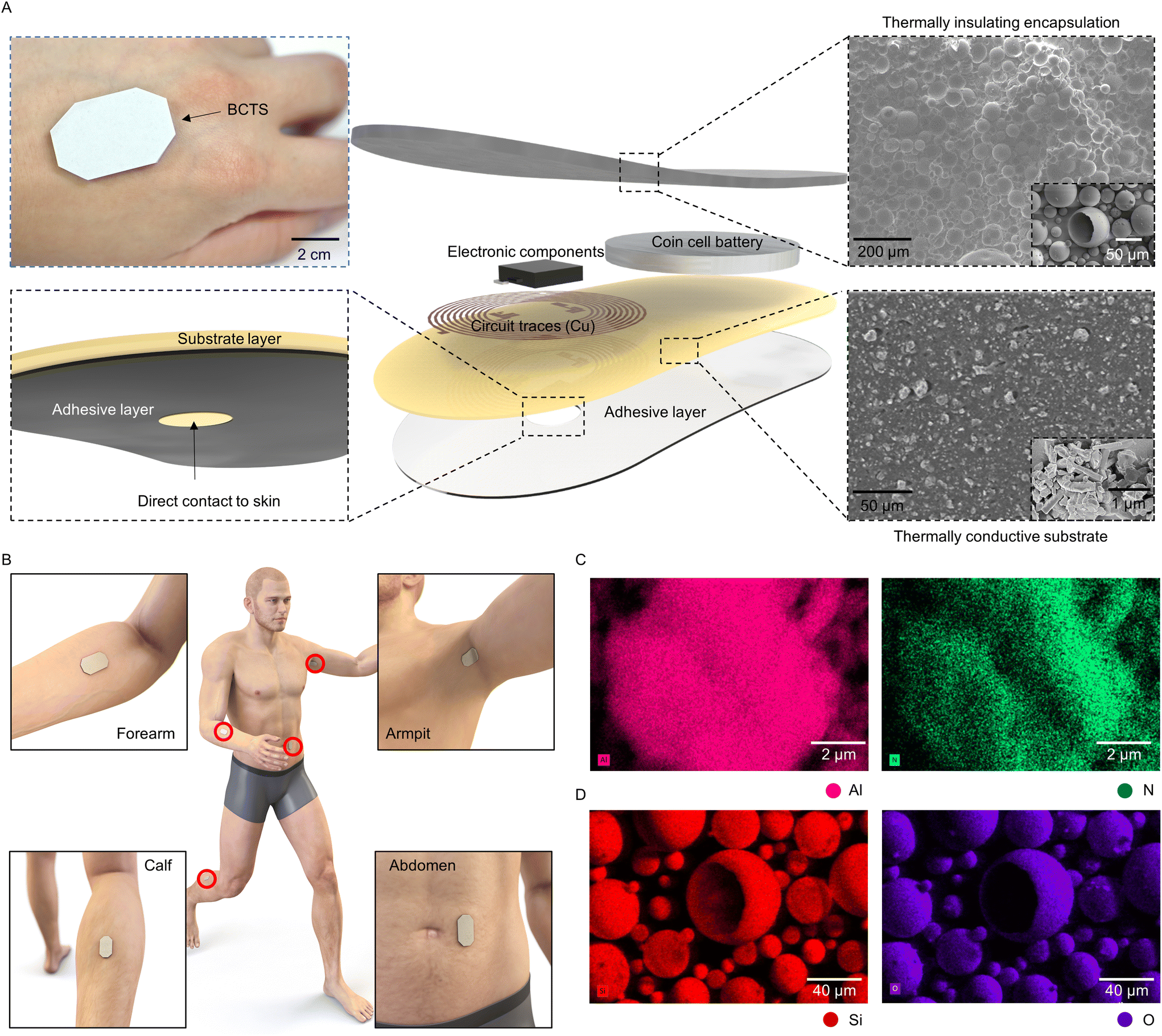 | ||
| Fig. 1 Thermally transient-resistant epidermal wireless electronics. (A) Photograph (top left), detailed material and geometry of the bilayer composite temperature sensor. In the adhesive layer, a pinhole exists to enable direct contact between the substrate and the skin. (B) Schematic of the temperature sensor attached to the forearm, armpit, calf and abdomen. (C) Examination of the scanning electron microscopy image for thermally conductive encapsulation and (D) thermally insulating substrate. Al: aluminum, N: nitrogen, Si: silicon, and O: oxygen. | ||
Results and discussion
For effective body temperature monitoring, a sensor attached to the skin should have the capability to measure the body temperature in isolation from the ambient environmental temperature. Meeting such criteria necessitates the utilization of a layered structure, wherein the lower section that interfaces with the skin is crafted from a thermally conductive composite, while the upper section is dedicated to thermal insulation. A feasible solution involves introducing thermally insulating particles, like hollow silica microspheres, into the upper section and incorporating conductive particles, such as aluminum nitride, in the lower section within the elastomer. Examination of the scanning electron microscopy image indicates that the distinct network of aluminum nitride exhibits a non-spherical morphology, serving as the thermally conductive pathway within the elastomeric substrate (Fig. 1C). In contrast, the silica particles chosen for thermal insulation consist of the confirmed atoms, silicon, oxygen, and sodium (Fig. 1D and ESI Fig. S1†). The particles have a hollow spherical structure in which the air within the cavities, with a specific thermal conductivity value of 0.03 W m−1 K−1,27 serves as the primary insulating element. Here, the absence of prominent peaks in the X-ray diffraction (XRD) graph associated with silica particles is visible, signifying their amorphous chemical structure (ESI Fig. S2†).28,29 This amorphous structure can synergistically contribute to a reduction in thermal conductivity, complementing the inherently low thermal conductivity of the air enclosed within the hollow silica particles.Heat transfer between the external environment and the encapsulant composites occurs in two major methods in our application context, namely conduction and convection.30 As illustrated in ESI Fig. S3,† once the heat flux enters the top surface doped with hollow silica microspheres, less heat enters through the matrix compared to pristine PDMS. Coupled with the hollow structure of silica, the transport of vibrational energy is impeded due to the disordered arrangement in the amorphous structure and hence the reduced heat flux.31 This minimizes the effects of convective heat transfer from reaching the thermistor housed by the microcontroller. Conversely, conduction between the epidermis and the sensor is encouraged in our proposed system. The addition of aluminum nitride induces the creation of ‘heat transfer paths’ within the PDMS matrix, which means that the phonons arising from the intrinsic crystalline structure of aluminum nitride create a conduction pathway for more heat flux to pass compared to pristine PDMS. This phenomenon has been named the thermal percolation effect.32 Ultimately, the interface between the two heterogeneous layers where the sensing component is situated plays a crucial role. Therefore, it is imperative to ensure that the temperature at this interface closely aligns with the temperature measured from the beneath, i.e. the skin temperature. To assess the temperature maintenance in this region, thermal simulations were conducted. Under varied ambient temperature conditions (−10 °C, 0 °C, 25 °C, and 45 °C), the bilayer composite layout exhibited superior performance in maintaining the temperature at the interface close to 37 °C when compared to pristine PDMS. For instance, the simulation indicated that at an ambient temperature of 0 °C, the temperature deviation at the interface, in comparison to the conduction temperature, could be as large as 0.2 °C for the bilayer composite and 2 °C for pristine PDMS, as illustrated in ESI Fig. S4.†
An alteration in the thermal conductivity of intrinsic silicone is evident, with a decrease when mixed with hollow silica microspheres and an increase when combined with aluminum nitride (Fig. 2A and B). The observed change is directly related to the particle ratio, as expected, but it involves a trade-off between improved thermal properties and decreased elasticity (Fig. 2C). In our study, we utilized a composite material to construct the sensor's encapsulant and substrate, with each comprising 30 wt% hollow silica microspheres and 60 wt% aluminum nitrides. This thoughtfully selected composition was intended to achieve an equivalent Young's modulus of 3.4 MPa for both layers while significantly enhancing the thermal conductivity. Specifically, the measurements, with thermal conductivity values of 0.09 W m−1 K−1 for the hollow silica composite and 0.71 W m−1 K−1 for the aluminum nitride composite, highlight enhancements of 40% and 370%, respectively, compared to 0.15 W m−1 K−1 of intrinsic silicone, demonstrating improved thermal regulation capabilities. Additionally, these composite materials offer stretchability of more than 30% without incurring any damage, making them exceptionally suitable for integration into wearable sensors (ESI Fig. S5†).
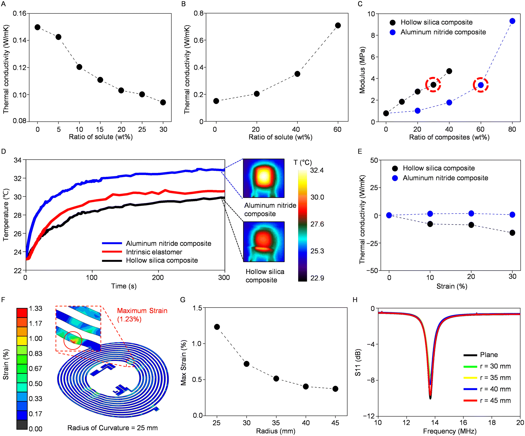 | ||
| Fig. 2 Characterization of intrinsic silicone, the hollow silica composite, and the aluminum nitride composite. (A) Thermal conductivity testing with varying concentrations of the hollow silica composite and (B) the aluminum nitride composite. (C) Modulus comparison of the hollow silica composite and the aluminum nitride composite based on varying concentrations of the particle. (D) Graph showing temperature changes and the corresponding infrared images of intrinsic silicone, the aluminum nitride composite and the hollow silica composite under the same heat exposure. (E) Variations in the thermal conductivity of the two composites at different degrees of strain. (F) Finite-element analysis of the inductive antenna under a bending force with a radius of 25 mm. (G) The maximum strain applied to the circuitry based on various bending radii. (H) Scattering parameter data of inductive antenna based on different bending radii. | ||
To evaluate the thermal properties, including the capability to conduct or insulate heat, of the substrate and encapsulation composites produced by blending particles in the mentioned ratios, we conducted infrared experiments to compare these composites with intrinsic silicone. Samples of uniform thickness were subjected to uniform heating via a resistive heater, yielding distinct temperature profiles: the aluminum nitride composite demonstrated the quickest temperature response, reaching the saturation temperature earlier, while the hollow silica microsphere composite exhibited a slower temperature change (Fig. 2D). The variance in these temperature response rates aligns closely with the thermal conductivity measurements obtained in previous assessments, where the thermal insulating and conducting composites showed differences of 40% and 370%, respectively, when compared to intrinsic silicone. We also tested the composites’ stability of physical characteristics amid temperature changes. Both the PDMS–hollow silica microsphere composite and PDMS–aluminum nitride composite are tested with a thermogravimetric analyzer (TGA) to test weight reduction and subsequent thermal decomposition (ESI Fig. S6†). The conducted experiment yielded significant weight loss when the encapsulating material was heated to around 350 °C. Subsequently, differential scanning calorimetry (DSC) was conducted to see if a significant phase change occurred in our predefined temperature range between −90 °C and 350 °C. The results exhibited no signs of latent heat exchange in this range; hence, there is a stable temperature measuring range from −50 °C to 200 °C for this composite, which is the suitable range for measuring the skin temperature (ESI Fig. S7†). Collectively, these findings suggest that these materials have the capability to effectively and stably conduct or insulate heat when utilized in temperature sensor applications.
Components of wearable temperature sensors must reliably function even when subjected to strain induced by skin stretching or subject movement. Therefore, assessing the thermal conductivity of each composite under strain is vital to ensuring their effectiveness under such conditions. Fig. 2E illustrates the alteration in the thermal conductivity for both the hollow silica composite and the aluminum nitride composite under strains of up to 30%. The aluminum nitride composite displays minimal change in its thermal conductivity, while the hollow silica composite exhibits a slight decrease when subjected to strain. This reduction in thermal conductivity, which is a favorable characteristic of an encapsulating layer of a temperature sensor, may be attributed to the elongation of the horizontal axis during stretching, leading to an increased density of thermally insulating particles along the vertical heat transfer pathway (ESI Fig. S8†).
Mechanical finite-element analysis further confirms the mechanical flexibility of our sensor with the composite bilayer when subjected to external bending and stretching (Fig. 2F and ESI Fig. S9†). The analysis indicated that strains remained below 1% until a 30 mm radius, with approximately 1.2% strain observed in the copper electrode embedded in the composites at a 25 mm radius (Fig. 2G). Also, when a horizontal stretching force is applied, the circuitry does not break or experience excess strain even when the device is stretched up to 10%. The results confirm that our device can operate without being damaged even under external stretching or bending. The inductive antenna utilized for data transmission between the smartphone and the temperature sensor, as elaborated later, exhibits minimal impact under similar bending conditions, maintaining a resonant frequency of 13.56 MHz with negligible scattering parameter losses (e.g., S11) (Fig. 2H). These findings demonstrate that the circuitry can maintain effective operation without suffering significant damage, even when subjected to bending induced by body movements when worn, indicating its durability and suitability for wearable sensors.
The Bilayer Composite Temperature Sensor (BCTS) comprises composite layers with contrasting thermal characteristics, a near-field communication chip, an inductive antenna, and a power source (Fig. 3A). As detailed in the Method section, the inductive antenna has a self-inductance of 1.38 μH and a self-resonance frequency of 84.35 MHz. The resonant frequency (f0) of the inductor–capacitor parallel circuit can be expressed as follows:
 | (1) |
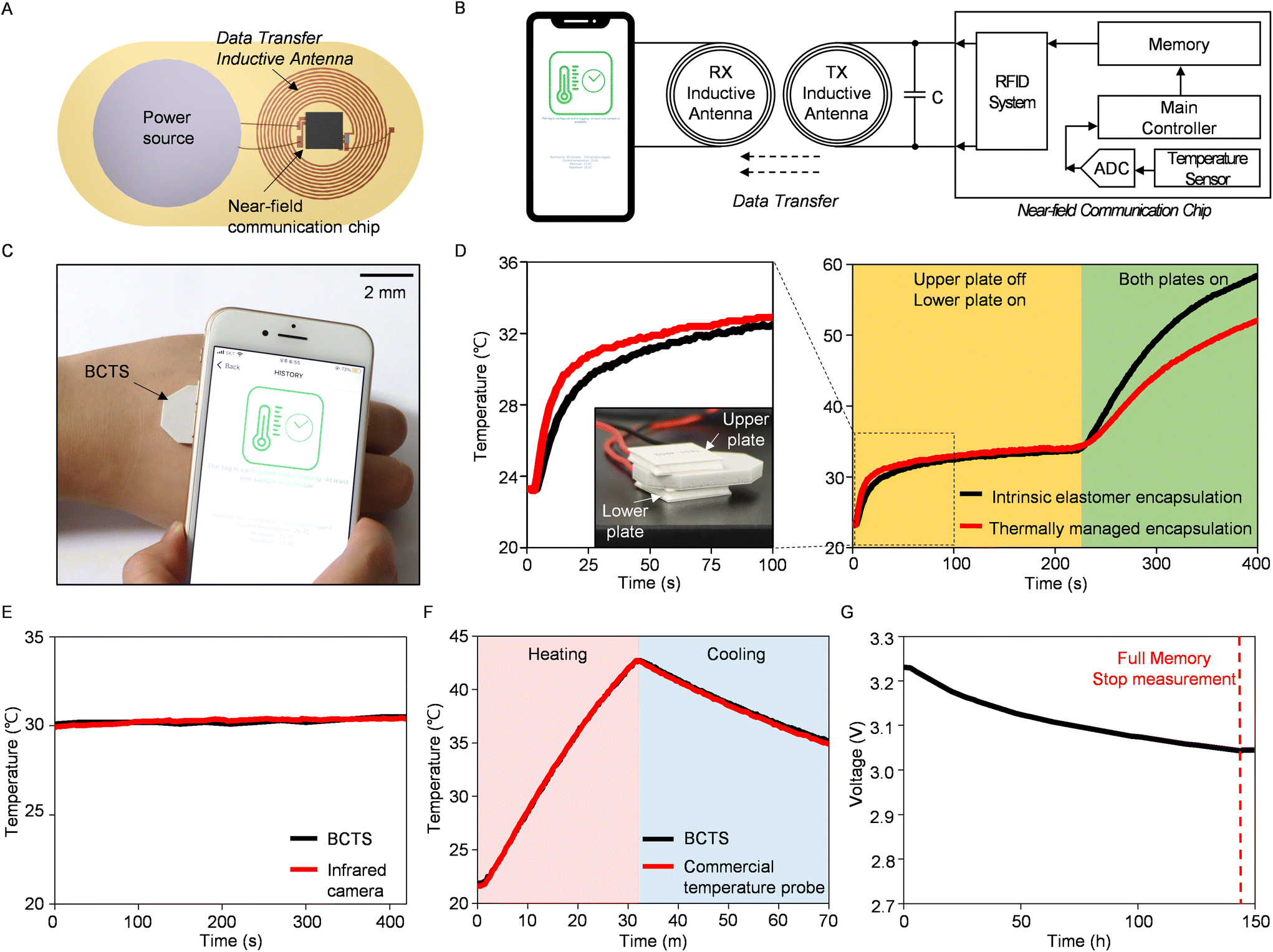 | ||
| Fig. 3 The characteristics of the bilayer composite temperature sensor (BCTS). (A) The top-view schematic illustration of BCTS. (B) Block diagram of the BCTS circuitry. When a data transmission request is received from a smart device, the stored data in BCTS are transmitted from the frequency-matched transmitting (TX) antenna to the receiving (RX) antenna wirelessly. (C) Photograph of the wireless data transmission between a smart device and the BCTS. (D) Experiment with differently encapsulated temperature sensors interposed between thermoelectric plates. The graph on the left is a partially enlarged graph with an inserted photograph of the actual experimental setup. (E) Performance comparison of the BCTS with an infrared camera and (F) with a commercial temperature probe. (G) Voltage variation of a power source during the BCTS operation. The red-dashed line at 144 hours indicates the cessation point of BCTS due to filled flash memory. | ||
All the electrical components are interconnected and enclosed within the bilayer composite, ensuring both mechanical stability and portability for a compact wireless device. The temperature sensor with a total thickness of 3.7 mm integrated into the near-field communication chip enables precise thermal measurements with an absolute temperature accuracy of 0.3 °C through physical contact with a thermal pad (Fig. 3B). Here, the sensor measures body temperature with a moderate response time of 19 seconds (from 19 °C to 42 °C, ESI Fig. S10†), and the data are then stored in flash memory. Then, data are transmitted wirelessly when the user wishes to extract the information (Fig. 3C). A comparative experiment further confirms the effectiveness of the thermally managed composite layers within the BCTS. In this experiment, we positioned two different types of sensors, one with an intrinsic elastomer and the other with thermally managed composites, between two thermoelectric heaters (Fig. 3D). When we activated the lower heater, the thermally managed encapsulated device demonstrated a faster response to the applied heat, primarily due to the higher thermal conductivity of the aluminum nitride composite at its base. Conversely, the hollow silica composite acted as a thermal insulator, resulting in lower temperature measurements when compared to the intrinsic elastomer encapsulated device after activating the upper heater. This outcome emphasizes the BCTS's ability to sensitively detect localized heat and protect against external interference.
Comparing BCTS with conventional thermometers can demonstrate its suitability as epidermal sensing electronics. Contactless thermal measurements using infrared radiation yield results nearly identical to those obtained with BCTS (Fig. 3E). In an aquatic environment that experiences temperature changes involving heating and cooling, the similarity in results with a commercial temperature probe confirms the satisfactory performance of BCTS (Fig. 3F). Another notable aspect in the test is the underwater (phosphate buffered solution, pH 7.4) operation of BCTS, which was confirmed for a continuous 70-minute duration under dynamic temperature conditions. This capability is achieved due to its seamless bilayer encapsulation, which is inherently hydrophobic.33 With current consumption of 0.94 mA during the temperature reading, BCTS exhibits an operational lifetime of over 6 days with a 140 mA h power source (Fig. 3G). Long-term durability and skin affinity tests ensure prolonged usability of the integrated device, along with the electrical lifespan (ESI Fig. S11 and S12†). Consequently, BCTS demonstrates long-term and robust performance across varying environmental conditions, suggesting its potential as an epidermal temperature sensor, in addition to the functional validation.
The study extends its focus to the monitoring of body temperature within the context of intense exercise routines under both relatively warm and cold ambient conditions (Fig. 4A). In the scenario of exercising under relatively cold ambient conditions (18 °C), the armpit temperature, closely linked to the core body temperature, consistently decreases. This initial decline in skin temperature aligns with the findings from a similar study conducted elsewhere, which proposed that the reduction in skin temperature during the initial phase of exercise is attributed to non-thermal factors inducing vasoconstriction.34 Additionally, the calf muscle temperature exhibits a steady increase, while the abdominal temperature remains relatively constant, collectively indicating an increased blood flow to certain body areas, such as calf muscle during repetitive squatting exercises.35,36 A similar temperature change observed during exercise in a moderately warm environment (1 °C) confirms that the composite encapsulant effectively shields the temperature sensing element from its atmospheric surroundings. This protection remains effective even in the presence of rapid movements that could otherwise impact the sensor's thermal environment.
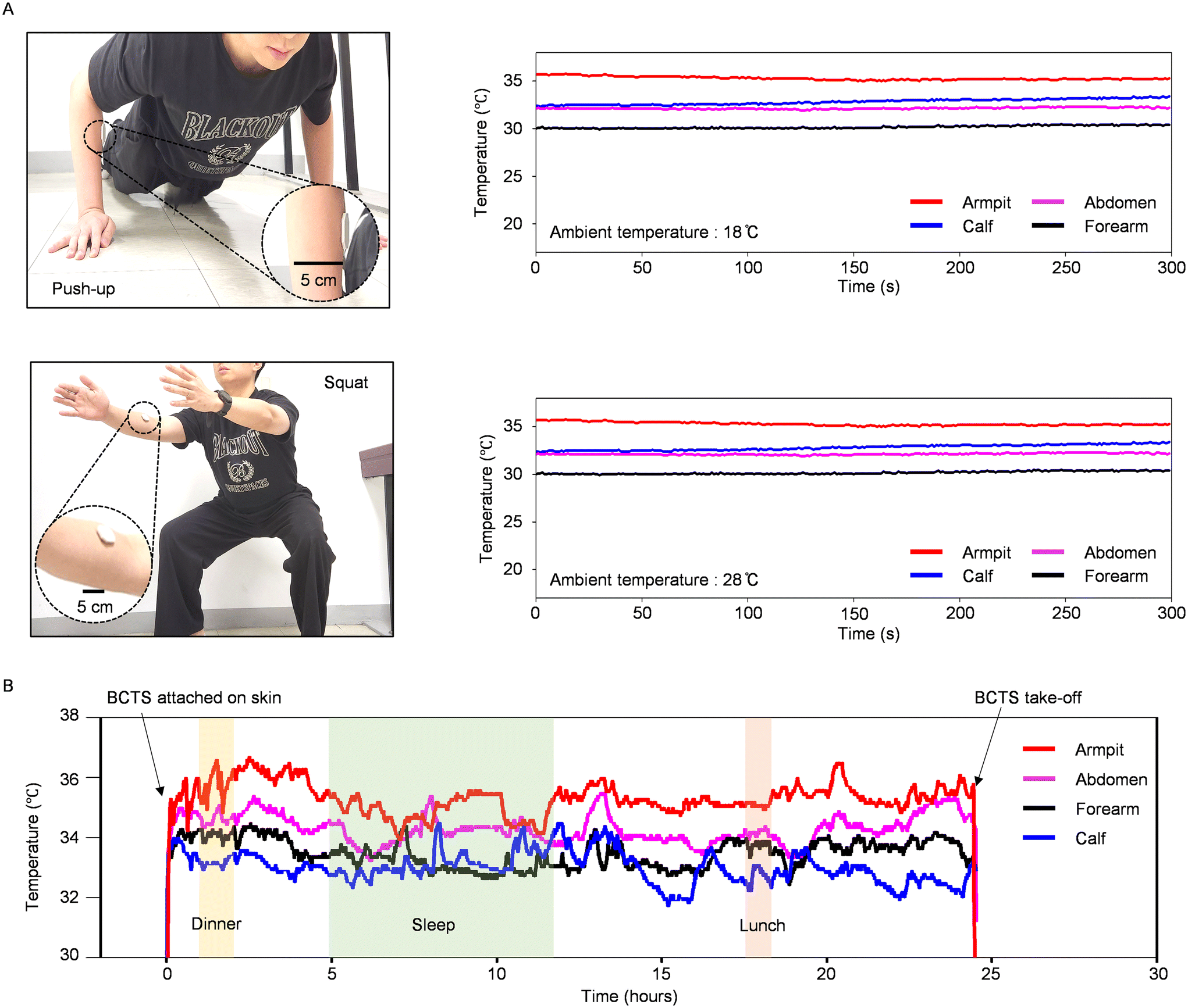 | ||
| Fig. 4 Temperature sensing in real-life application contexts. (A) BCTS reading of skin temperatures at 4 anatomical regions (armpit, abdomen, forearm and calf) during an exercise routine at 18 °C ambient temperature (top right). BCTS reading at the same body regions during the same exercise under 28 °C ambient conditions (bottom right). (B) 24-hour monitoring of skin temperature at four anatomical regions (armpit, abdomen, forearm and calf) using the BCTS. Food intake (yellow and pink) and sleep (green) periods are highlighted in different colors. | ||
Other advantages include its light weight, flexible structure, and energy-efficient operation, all of which are well-suited for the investigation of circadian rhythms spanning more than 24 hours. For example, body temperature serves as an indicator of essential daily processes, such as the digestive events. Our 24-hour temperature monitoring in this study demonstrates that the temperatures obtained from the armpit consistently show higher values when compared to the axillary temperature, with a tendency to decrease during sleep periods relative to periods of physical activity (Fig. 4B), aligning with similar findings reported elsewhere.37 Here, the occasional temperature fluctuations in the forearm and calf muscles during the sleep period can be attributed to movements and shifts in axillary body regions, as well as the use of blankets to cover the body. On the other hand, temperature exhibited a noticeable increase, rising to 36.2 °C, during meal consumption, also agrees well with the results reported in other studies.38 With its ability to accurately track disturbed sleep and various physical activities, our sensing system's data can potentially provide insights into the fundamental factors influencing well-being.
Conclusion
The objective of this study is the development of a temperature sensing system that not only reduces errors stemming from thermal interactions with the surrounding environment, but also utilizes electronic components for wireless data transmission. The evaluation of the modified thermal and mechanical properties of the encapsulant and substrate in the wireless temperature sensor validates its suitability to be used as an epidermal temperature sensor, where characteristics like flexibility, thermal insulation from the environment, and efficient thermal conduction from the body are essential. The epidermal temperature sensing system in this study has the capacity for data acquisition outside of the intensive care unit, making it effective in tracking temperature in daily life scenarios. The circuit design using the near-field communication protocol can extend its functionality not only to wireless communication, but also to wireless power transmission (ESI Fig. S13†). Such an additional functionality can overcome the limitation of the battery, which imposes the most significant restriction on the size of the device. In addition, enhancing the device with a more optimized geometry, such as a porous structure, has the potential to improve the breathability of the wearable temperature sensor. Consequently, the reduction in dimension and weight allows for scalability, expanding the application to infants or small animals.39–41 A reliable chip-based temperature sensing system and methods to mitigate external errors can offer a suitable solution for elderly human subjects experiencing a decline in internal heat generation due to aging.19 This interdisciplinary effort may provide the foundational framework for the encapsulation strategy in the advancement of next-generation wireless epidermal electronics.Method
Fabrication of the bilayer composite temperature sensor
The sensor fabrication process starts with the spin coating of a PDMS (Sylgard 184, Dow Corning) and aluminum nitride (241903, Sigma-Aldrich) composite at 800 rpm for 60 seconds, followed by baking at 90 °C for 10 minutes. The PDMS–aluminum nitride mixture is prepared with a 60 wt% ratio of aluminum nitride in silicone, which would be the substrate (0.2 mm) of the sensor. Simultaneously, a copper circuit with a thickness of 10 μm is precisely cut using laser technology onto a water-soluble tape (Aquasol Corporation). Subsequently, the circuit, affixed to the tape, is meticulously transferred onto the aluminum nitride substrate. The tape is removed through water washing, leaving the copper circuit securely on the substrate. After the successful transfer of the circuit onto the aluminum nitride substrate, a capacitor for impedance matching and a sensor chip (NHS 3100, NXP Semiconductors) are integrated into the circuit. Additionally, a coin cell battery (CR1632, Panasonic) is soldered onto the system. Finally, the entire setup is encapsulated using a hollow silica microsphere (HEATBLOK-R20, ESAI) and PDMS mixture with a 30 wt% ratio of the composite and silicone (3.5 mm) to ensure protection and stability. The completed system has a width of 24 mm and a height of 40 mm.Comparison experiment of each layer through an infrared camera
In the infrared experiment, three sheets of equal thickness (0.3 mm) made of the aluminum nitride composite, hollow silica composite, and intrinsic silicone were placed on the same resistor heater. Upon applying voltage to the heater, it began emitting heat. The IR camera (FLIR A600, FLIR) measured the temperature on the side opposite to the heat source of each sheet for 300 seconds.Cross-sectional image of a hollow silica composite
The cross-sectional images of a hollow silica composite before and after deformation were captured using an optical microscope (HNM800, HiMaxTech Co., Ltd).Temperature measurements
Thermoelectric plate modules, which cool themselves with a forward bias and heat themselves with a reverse bias, were utilized to test the thermal performance of the composite-aided near-field communication temperature sensor. The bottom and top of the sensor system were sandwiched by the two plates (Thermoelectric module, TES1-4903) that were regulated to be at different temperatures (ESI Fig. S14†). The plate attached to the bottom was heated to 38.8 °C as soon as the experiment started and heating was continued for 230 seconds. Then, the plate attached to the upper part of the sensor was also heated to 88.2 °C and heating was continued for 170 seconds. The comparison experiment between the commercial temperature probe sensor used underwater and the sensor presented in this study was carried out in a beaker (ESI Fig. S15†). The beaker filled with phosphate buffered solution (LB001-02, WELGENE) was placed on a hot plate set to 90 °C for 30 minutes and then cooled to room temperature (ESI Fig. S16†). During this time, both the probe temperature sensor inside the water in the beaker and the sensor from this study measured the temperature.Mechanical simulation
The deformed shape of the device and the strain distribution induced when the device is bent are modeled using a commercial 3D finite-element analysis simulation program, ABAQUS. The hollow silica composite layer and the aluminum nitride composite layer consisted of twenty-node quadratic hexahedron elements (C3D20 in ABAQUS). The copper circuit consisted of four-node shell elements (S4 in ABAQUS). We verified the mechanical stability of the device, which was deformed according to the predefined bending radius or the predefined axial strain of the composites, by comparing the maximum strain induced in the copper circuit of the device with its failure strain, 1%. The elements were finely divided until the accuracy of the result was no longer improved and it was converged (i.e., mesh convergence). The Young's modulus (E) and Poisson's ratio (ν) were Esilica = 3.42 MPa and νsilica = 0.44 for the hollow silica composite; Ealuminum nitride = 3.39 MPa and νaluminum nitride = 0.42 for the aluminum nitride composite; Ecopper = 119 GPa and νcopper = 0.34 for copper.Experiment comparing hot and cold environments after attaching temperature sensors
The sensors were affixed to the abdomen, forearm, calf and armpit, and the test subjects engaged in physical activities in environments set at controlled temperatures of 18 °C and 28 °C, respectively. The participants performed 20 push-ups, 50 squats and 15 burpee tests for 2 minutes and 30 seconds. After the exercises, there was a similar rest period of 2 minutes and 30 seconds.Protocols for human subject studies
The studies were approved by the Sungkyunkwan University Institutional Review Board, Suwon, Korea (IRB File No. SKKU 2023-10-036). The male subject (age 27, 174 cm, 70 kg) participated in the 24-hour long-term study and exercise in different temperature environments. A double-sided medical silicone adhesive (2477P, 3M) secured the device to the skin at the region of interest. For the 24-hour and exercise study, the custom-designed temperature sensors under study are body-mapped and placed on the forearm, armpit, abdomen, and calf. After each measurement session, sterilization of the device was executed using 70% isopropyl alcohol.Thermal characterization of the composites
The thermal conductivity measurements were conducted on each film sample with a thickness of 1 mm and dimensions of 50 mm by 50 mm. The measurements were performed using a thermal conductivity instrument (Trident MTPS, C-THERM) that employs the modified transient plane source method. In this method, heat is generated through the application of current to the coil attached to the lower surface, and the changes in voltage are calculated to determine the thermal conductivity. Each sample was measured five times. TGA (TGA 8000, PerkinElmer) was used to investigate the range of application temperatures and degradation temperatures of the PDMS/aluminum nitride and PDMS/hollow silica microsphere composites by heating from 0 °C to 900 °C. The temperature rise was scheduled at 10 °C min−1. Using this information, the testing temperature range of DSC (DSC 250, TA Instruments) was chosen, then the samples were heated to 250 °C, cooled to −80 °C, and then heated again to 250 °C at 10 °C min−1 at all stages while heat flow was being measured. Latent heat was measured from final heating to exclude the effects from thermal history.Thermal simulation
The temperature profile of the composite layer compared to pristine PDMS at different ambient temperatures, while being attached to the skin, is modeled using commercial 3D finite element analysis simulation software ANSYS 2023 R1. The simulation was conducted with the assumption of free convection from the ambient environment, device not generating heat, and no deformation within the device. The PDMS–hollow silica microsphere composite had a thermal conductivity of 0.09 W m−1 K−1 and the PDMS–aluminum nitride composite layer had a thermal conductivity of 0.71 W m−1 K−1, each corresponding to the experimentally verified values. The top surface as well as the sides of the device are subject to free convection at 0 °C, 10 °C, 25 °C, and 45 °C, while the bottom of the surface was influenced by conduction at a fixed temperature of 37 °C, which is the approximate body temperature. The convective heat transfer coefficient was set at 10 °C.X-ray related characterization of aluminum nitride and hollow silica microspheres
Each powder sample of aluminum nitride and hollow silica microspheres is magnified under a scanning electron microscope (SEM). The equipment used is a focused ion beam SEM (Helios 5 UC, FEI). Addition of 3 nm of platinum was required for providing conductivity. After the SEM image was obtained, dispersive X-ray spectroscopy (EDS) for elemental mapping was performed for each powder sample used to create the composite (ESI Fig. S17†). To ensure the results from EDS, X-ray photoelectron spectroscopy (XPS) (AXIS Supra+, Kratos) was also conducted on the same powder samples. XPS requires that carbon is added to the powder samples for equipment calibration. Finally, the degrees of crystallinity of the samples were tested using XRD (D8 Discover, Bruker). The results of the silica samples were confirmed by examining the sample using a long scan.Skin affinity and biocompatibility test
The device was attached to the forearm of a male subject (age 28, 177 cm, 72 kg) for 24 hours to observe changes in the skin. The device was attached to the skin and then detached and reattached every 6 hours, and photographs were taken of each state.Long-term durability test
The fabricated sensor was immersed in water in a beaker for 24 hours and stirred with a stir bar. The beaker was heated on a hot plate, the water temperature was maintained at 28 °C, and the stirring was performed at 60 RPM. Similarly, the device was taken out from the water every 6 hours, and the device was exposed to the same heat source to measure the temperature.Self-inductance and self-resonance frequency measurement
The self-inductance of the inductive antenna was measured in the low-frequency range of 50 to 150 kHz to mitigate the influence of parasitic capacitance. The self-resonance frequency, accounting for the parasitic capacitance, was measured at 13.56 MHz. Both values were obtained through S11 Smith chart analysis using a vector network analyzer (E5072A, Keysight).Wireless power transmission measurement
A power distribution controller (A6102-0198, NEUROLUX) was utilized as the wireless power source. The controller was connected with wires wound at a vertical interval of 4 cm, encircling a 25 × 25 cm-sized acrylic cage. After impedance matching with an antenna tuner (AUT-0150, NEUROLUX), the output power was set to 4 W with a 100% duty cycle for operation. The wireless recharging device was positioned at the center of the cage, and the output current power was measured using a digital multimeter (NI USB-4065, National Instruments).Data availability
The data that support the findings of this study are available from the corresponding author upon request.Author contributions
D. K. designed and tested the circuitry and insulation methodology. W. K. manufactured the circuitry and the conductive composite. J. K. examined the electronics and performed material characterization. B. K. executed mechanical finite element analysis. D. L assisted theoretical thermal calculations and thermal finite element analysis. S. M. W. supervised the research. All authors contributed to the interpretation of the results and commented on the manuscript.Conflicts of interest
The authors declare no competing interests.Acknowledgements
This work was supported by the BK21 Four project and the SKKU ICT Research and Education Foundation. We thank the researchers at the Advanced Institute of Convergence Technology (Suwon, South Korea) for providing consultations on material characterization. We got approval from our institute and the participants of our study before measuring skin temperatures. S. M. W. acknowledges the support by the National Research Foundation of Korea (NRF) grant funded by the Korean government (MSIP; Ministry of Science, ICT & Future Planning; Grant No. NRF-2021R1C1C1009410, IITP-2020-0-01821 and NRF-2022R1A4A3032913). S. M. W. acknowledges the support by the Nano Material Technology Development Program (2020M3H4A1A03084600) through the National Research Foundation of Korea (NRF) funded by the Ministry of Science and ICT of Korea. Y. P. acknowledges the support by the KERI Primary research program of MSIT/NST (grant number 23A01067).References
- S. R. Krishnan, C. J. Su, Z. Xie, M. Patel, S. R. Madhvapathy, Y. Xu, J. Freudman, B. Ng, S. Y. Heo and H. Wang, Small, 2018, 14, 1803192 CrossRef PubMed
.
- M. Zhang, P. Yang, T. Yu, M. C. Harmsen, M. Gao, D. Liu, Y. Shi, Y. Liu and X. Zhang, Heliyon, 2022, 8, e09128 CrossRef CAS PubMed
- G. P. Kenny and R. McGinn, J. Appl. Physiol., 2017, 122, 933–944 CrossRef PubMed
- J. D. Périard, T. M. Eijsvogels and H. A. Daanen, Physiol. Rev., 2021, 101, 1873–1979 CrossRef PubMed
- J. M. Fritz and J. R. McDonald, Phys. Sportsmed., 2008, 36, 50–54 CrossRef PubMed
- K. Patel and H. J. West, JAMA Oncol., 2017, 3, 1751–1751 CrossRef PubMed
- C. Dittner, E. Lindsund, B. Cannon and J. Nedergaard, Mol. Metab., 2019, 25, 20–34 CrossRef CAS PubMed
- S. Sözay, Y. Gökçe-Kutsal, R. Celiker, T. Erbas and O. Başgöze, Thyroidology, 1994, 6, 55–59 Search PubMed
- A. Dyszkiewicz and E. Kucharz, Pol. Arch. Med. Wewn., 2000, 104, 339–343 CAS
- S. Han, J. Kim, S. M. Won, Y. Ma, D. Kang, Z. Xie, K.-T. Lee, H. U. Chung, A. Banks, S. Min, S. Y. Heo, C. R. Davies, J. W. Lee, C.-H. Lee, B. H. Kim, K. Li, Y. Zhou, C. Wei, X. Feng, Y. Huang and J. A. Rogers, Sci. Transl. Med., 2018, 10, eaan4950 CrossRef PubMed
-
V. Surabhi, D. Spinello and D. Necsulescu, 2012 IEEE International Instrumentation and Measurement Technology Conference Proceedings, IEEE, 2012, pp. 1556–1560 Search PubMed
- J. A. Amendola, A. M. Segre, A. C. Miller, J. T. Hodges, A. P. Comellas, L. A. Polgreen and P. M. Polgreen, Open Forum Infect. Dis., 2023, 10, ofad214 CrossRef PubMed
- Y. Geng, R. Cao, M. T. Innocent, Z. Hu, L. Zhu, L. Wang, H. Xiang and M. Zhu, Composites, Part A, 2022, 163, 107269 CrossRef CAS
- F. Li, H. Xue, X. Lin, H. Zhao and T. Zhang, ACS Appl. Mater. Interfaces, 2022, 14, 43844–43852 CrossRef CAS PubMed
- D. Kim, N. Lu, R. Ma, Y. Kim, R. Kim, S. Wang, J. Wu, S. Won, H. Tao, A. Islam, J. Chung, H. Keum, M. McCormick, P. Liu, Y.-W. Zhang, F.G Omenetto, Y. Huang, T. Coleman and J.A Rogers, Science, 2011, 333, 838–843 CrossRef CAS PubMed
- H. Jeong, J. Y. Lee, K. Lee, Y. J. Kang, J.-T. Kim, R. Avila, A. Tzavelis, J. Kim, H. Ryu and S. S. Kwak, Sci. Adv., 2021, 7, eabg3092 CrossRef PubMed
- J. Kim, A. Banks, Z. Xie, S. Y. Heo, P. Gutruf, J. W. Lee, S. Xu, K.-I. Jang, F. Liu, G. Brown, J. Choi, J. H. Kim, X. Feng, Y. Huang, U. Paik and J. A. Rogers, Adv. Funct. Mater., 2015, 25, 4761–4767 CrossRef CAS
- S. Oh, J.-Y. Yoo, W.-Y. Maeng, S. Yoo, T. Yang, S. M. Slattery, S. Pessano, E. Chang, H. Jeong and J. Kim, Biosens. Bioelectron., 2023, 237, 115545 CrossRef CAS PubMed
- J. Waalen and J. N. Buxbaum, J. Gerontol., Ser. A, 2011, 66, 487–492 CrossRef PubMed
- S. J. Kang, H. Hong, C. Jeong, J. S. Lee, H. Ryu, J.-h. Yang, J. U. Kim, Y. J. Shin and T.-i. Kim, Nano Res., 2021, 14, 3253–3259 CrossRef CAS
- S. Vlassov, S. Oras, M. Timusk, V. Zadin, T. Tiirats, I. M. Sosnin, R. Lõhmus, A. Linarts, A. Kyritsakis and L. M. Dorogin, Materials, 2022, 15, 1652 CrossRef CAS PubMed
- C.-R. Yang, C.-D. Chen, C. Cheng, W.-H. Shi, P.-H. Chen and T.-P. Teng, Int. J. Therm. Sci., 2020, 155, 106431 CrossRef CAS
- Q.-h. Lin, S. He, Q.-q. Liu, J.-h. Yang, X.-d. Qi and Y. Wang, Compos. Sci. Technol., 2022, 226, 109528 CrossRef CAS
- J. Wei, M. Liao, A. Ma, Y. Chen, Z. Duan, X. Hou, M. Li, N. Jiang and J. Yu, Compos. Commun., 2020, 17, 141–146 CrossRef
- M. Giuffre, T. Heidenreich, P. Carney-Gersten, J. A. Dorsch and E. Heidenreich, Appl. Nurs. Res., 1990, 3, 52–55 CrossRef CAS PubMed
- A. Clark, J. Mangat, S. S. Tay, Y. King, C. Monk, P. White and P. Ewan, Allergy, 2007, 62, 744–749 CrossRef CAS PubMed
- B. Graczykowski, A. El Sachat, J. S. Reparaz, M. Sledzinska, M. R. Wagner, E. Chávez-Angel, Y. Wu, S. Volz, Y. Wu and F. Alzina, Nat. Commun., 2017, 8, 415 CrossRef CAS PubMed
- M. C. Rowe and B. J. Brewer, Comput. Geosci., 2018, 120, 21–31 CrossRef CAS
- L. Nascimento and A. Melnyk, J. Chil. Chem. Soc., 2017, 62, 3512–3514 CrossRef CAS
- J. H. Lienhard IV, A heat transfer textbook, Courier Corporation, 2013 Search PubMed
- W. X. Zhou, Y. Cheng, K. Q. Chen, G. Xie, T. Wang and G. Zhang, Adv. Funct. Mater., 2020, 30, 1903829 CrossRef CAS
- A. Chatterjee, R. Verma, H. Umashankar, S. Kasthurirengan, N. Shivaprakash and U. Behera, Int. J. Therm. Sci., 2019, 136, 389–395 CrossRef CAS
- J. C. McDonald, D. C. Duffy, J. R. Anderson, D. T. Chiu, H. Wu, O. J. A. Schueller and G. M. Whitesides, Electrophoresis, 2000, 21, 27–40 CrossRef CAS PubMed
- M. Torii, M. Yamasaki, T. Sasaki and H. Nakayama, Br. J. Sports Med., 1992, 26, 29–32 CrossRef CAS PubMed
- T. Blokker, E. Bucher, T. Steiner and J. P. Wehrlin, Front. Sports Act. Living, 2022, 4, 966203 CrossRef PubMed
- J. Pearson, D. A. Low, E. Stöhr, K. Kalsi, L. Ali, H. Barker and J. González-Alonso, Am. J. Physiol.: Regul., Integr. Comp. Physiol., 2011, 300, R663–R673 CrossRef CAS PubMed
- E. C. Harding, N. P. Franks and W. Wisden, Curr. Opin. Physiol., 2020, 15, 7–13 CrossRef PubMed
- K. Hayashi, N. Ito, Y. Ichikawa and Y. Suzuki, Appl. Physiol., Nutr., Metab., 2019, 44, 22–30 CrossRef CAS PubMed
- A. D. Mickle, S. M. Won, K. N. Noh, J. Yoon, K. W. Meacham, Y. Xue, L. A. McIlvried, B. A. Copits, V. K. Samineni and K. E. Crawford, Nature, 2019, 565, 361–365 CrossRef CAS PubMed
- S. S. Kwak, S. Yoo, R. Avila, H. U. Chung, H. Jeong, C. Liu, J. L. Vogl, J. Kim, H. J. Yoon and Y. Park, Adv. Mater., 2021, 33, 2103974 CrossRef CAS PubMed
- H. U. Chung, B. H. Kim, J. Y. Lee, J. Lee, Z. Xie, E. M. Ibler, K. Lee, A. Banks, J. Y. Jeong and J. Kim, Science, 2019, 363, eaau0780 CrossRef CAS PubMed
Footnotes |
| † Electronic supplementary information (ESI) available. See DOI: https://doi.org/10.1039/d3nr05784d |
| ‡ These authors contributed equally to this work. |
| This journal is © The Royal Society of Chemistry 2024 |