
Pyrolysis-free synthesis of a high-loading single-atom Cu catalyst for efficient electrocatalytic CO2-to-CH4 conversion†
Jiawei
Li‡
ab,
Yawen
Jiang‡
c,
Jiayi
Li
a,
Xinyu
Wang
ab,
Hengjie
Liu
 a,
Ning
Zhang
*ab,
Ran
Long
*a and
Yujie
Xiong
*ab
a,
Ning
Zhang
*ab,
Ran
Long
*a and
Yujie
Xiong
*ab
aNational Synchrotron Radiation Laboratory, Hefei National Research Center for Physical Sciences at the Microscale, Key Laboratory of Precision and Intelligent Chemistry, School of Chemistry and Materials Science, Department of Environmental Science and Engineering, University of Science and Technology of China, Hefei, Anhui 230026, China. E-mail: zhangning18@ustc.edu.cn; longran@ustc.edu.cn; yjxiong@ustc.edu.cn
bSustainable Energy and Environmental Materials Innovation Center, Suzhou Institute for Advanced Research, University of Science and Technology of China, Suzhou, Jiangsu 215123, China
cDeep Space Exploration Laboratory, Hefei, Anhui 230026, China
First published on 1st December 2023
Abstract
Electrocatalytic CO2-to-CH4 conversion provides a promising means of addressing current carbon resource recycling and intermittent energy storage. Cu-based single-atom catalysts have attracted extensive attention owing to their high intrinsic activity toward CH4 production; however, they suffer from uncontrollable metal loading and aggregation during the conventional pyrolysis process of carbon-based substrates. Herein, we developed a pyrolysis-free method to prepare a single-atom Cu catalyst anchored on a formamide polymer substrate with a high loading amount and well atomic dispersion through a mild polycondensation reaction. Owing to the isolation of copper active sites, efficient CO2-to-CH4 conversion is achieved over the single-atom Cu catalyst, along with the significant suppression of C–C coupling. As a result, the optimal single-atom catalyst with 5.87 wt% of Cu offers high CH4 faradaic efficiencies (FEs) of over 70% in a wide current density range from 100 to 600 mA cm−2 in the flow cell, together with a maximum CH4 partial current density of 415.8 mA cm−2. Moreover, the CH4 FE can reach 74.2% under optimized conditions in a membrane electrode assembly electrolyzer. This work provides new insights into the subtle design of highly efficient electrocatalyst for CO2 reduction.
 Ning Zhang | Dr Ning Zhang received his B.S. degree (in 2013) and PhD. (in 2018) in Chemistry from the University of Science and Technology of China (USTC). From 2018 to 2022, he worked as a Postdoctoral Fellow at Hong Kong Polytechnic University. He joined the USTC faculty in 2022 and is currently a professor of Chemistry and Environmental Engineering. His research interests focus on the rational design of functional catalyst systems for electrochemical molecular upgrading. |
1. Introduction
The massive use of fossil fuels has compelled human beings to directly confront two serious problems: the greenhouse effect and the energy crisis.1 Therefore, seeking effective approaches toward utilizing renewable energy is imperative. Electrocatalytic CO2 reduction (CO2RR) to highly value-added commodity chemicals is an appealing method in terms of both carbon neutrality and intermittent energy storage.2 Among various desired products, methane (CH4) has received specific attention from research communities owing to its highest value of mass heat (ca. 56 kJ g−1) compared to other hydrocarbons,3 as well as its fundamental applications in modern industries.4 However, electrocatalytic CO2-to-CH4 conversion is an unfavorable reaction as 8 electrons are essentially required with various elementary steps (i.e., CO2 + 8H+ + 8e− → CH4 + 4H2O). In this regard, it is still a great challenge to electrochemically produce CH4 with a high selectivity and productivity (i.e., faradaic efficiency (FE) and current density).In general, the rational design of advanced electrocatalyst candidates is a prerequisite for improving the catalytic activity. Among the tremendous alternatives for the CO2RR, Cu-based electrocatalysts have been extensively studied to produce hydrocarbons beyond two-electron products (i.e., CO and formate) by the controllable chemical affinities of various CO2RR intermediates.5,6 However, the kinetically favorable C–C coupling on the Cu surface generates various multi-carbon products, largely hindering the selectivity of the desired CH4 product. Isolating Cu active sites as single atom states is an effective approach to inhibit the C–C coupling during the CO2RR, thus facilitating multielectron-reduction to CH4.7 Presently, a mainstream method for the synthesis of single-atom catalysts is to calcinate the mixture of metal precursors with C and N sources, in which the single atoms are conventionally anchored on carbon-based substrates coordinated with nitrogen ligands.8–10 The C and N sources can be small molecular compounds (such as dopamine,11 pyrrole12 and o-phenylenediamine13), polymers (such as polyphthalocyanine14 and polyaniline15) and carbon materials (such as carbon quantum dots,16 graphene8,17 and metal–organic frameworks18,19). However, the carbon-based substrates derived from these substances usually have a relatively low N content, limiting the loading amount of metal single atoms. Additionally, the calcination treatment under high-temperature conditions leads to the agglomeration of metal atoms.18 To this end, carbon-based substrates with a high N content and without high-temperature calcination are particularly desirable for loading Cu single atoms. Specifically, a formamide polymer (FAP) is proposed as an ideal carrier20 because its theoretical atomic ratio of C and N reaches 1![[thin space (1/6-em)]](https://www.rsc.org/images/entities/char_2009.gif) :1, and it can be synthesized by a polycondensation reaction under relatively low temperatures. When the metal precursors are introduced into the formamide polycondensation process, the rich N atoms can coordinate with metal atoms to provide the single-atom catalyst with a controllable loading amount and high atomic dispersion.
:1, and it can be synthesized by a polycondensation reaction under relatively low temperatures. When the metal precursors are introduced into the formamide polycondensation process, the rich N atoms can coordinate with metal atoms to provide the single-atom catalyst with a controllable loading amount and high atomic dispersion.
Leveraging the advantages of the aforementioned formamide polycondensation process, herein, we successfully synthesized the single-atom Cu catalysts anchored on the FAP substrate. Synchrotron radiation-based characterizations confirm that the anchored Cu species is atomically dispersed with a high loading amount. As expected, the as-obtained single-atom Cu catalyst supported on FAP shows excellent performance for electrocatalytic CO2RR to CH4. In the conventional flow cell apparatus, the optimal electrocatalyst with a 5.87 wt% Cu loading amount achieves high CH4 Fes of over 70% in the wide current density ranging from 100 to 600 mA cm−2, together with a maximum CH4 partial current density of 415.8 mA cm−2. Electrochemical in situ spectroscopic measurements uncover the facilitated formation of *COOH and *CH3O intermediates, meaning the favorable CH4 production on single-atom Cu active sites. When the catalyst is encapsulated in the membrane electrode assembly (MEA) electrolyzer, it can reach the CH4 FE of up to 74.2% at 4.1 V cell potential and can maintain more than 50% CH4 FE after a long-term 13 h continuous operation.
2. Experimental section
2.1. Synthesis of single-atom Cu catalysts supported on FAP
A certain amount of Cu(NO3)2·3H2O was added into 60 mL formamide. The mixture was ultrasonically treated for at least 30 min to ensure complete dissolution and then transferred into a 100 mL Teflon-lined stainless-steel autoclave and kept at 180 °C for 12 h. The product was collected by centrifugation, washed with deionized water several times and then dried in a vacuum oven at 60 °C overnight. The obtained single-atom Cu catalysts supported on formamide polymers with different amounts of Cu(NO3)2·3H2O (0.3 mmol, 0.6 mmol, 1.2 mmol, 1.8 mmol) were denoted as FAP–Cu-x, where x is the feeding Cu amount. The obtained formamide polymer without Cu(NO3)2·3H2O was denoted as FAP.2.2. Electrochemical measurement
All electrochemical measurements were conducted using an electrochemical workstation (CHI 660e) equipped with a high-current amplifier (CHI 680c). Flow cell and MEA electrolyzer were used for the electrochemical CO2 reduction reaction. The preparation of the gas diffusion electrode (GDE) loading of our catalysts is described in the ESI.† For the flow cell, a GDE, nickel foam (1.5 × 1.5 cm2), and Ag/AgCl electrode were used as the cathode, anode and reference electrode, respectively. The active surface areas of the cathode and the anode are both 1 cm2. An anion exchange membrane (Fumasep FAB-PK-130) was employed to separate the cathode and anode. The polarization curve and constant current electrolysis were performed in a 1 M KOH aqueous solution as the electrolyte with high-purity CO2 gas was continuously supplied to the cathode. The electrolyte was circulated into both the anode and cathode sides with a flow rate of 10 mL min−1 controlled by peristaltic pumps. The CO2 gas flow rate was set to 50 mL min−1 using a mass flow controller. Typically, constant current electrolysis was conducted for 600 s. The ohmic loss between the working and reference electrodes was measured via electrochemical impedance spectroscopy (EIS) under open circuit potential, and 85% ohmic resistance correction was applied. The potentials were calibrated with respect to the reversible hydrogen electrode (RHE) according to the following equation: E(vs. RHE) = E(vs. Ag/AgCl) + 0.0592 × pH + 0.197. For the MEA electrolyzer, the prepared GDE and IrOx/Ti electrodes were used as the cathode and anode, respectively. The active surface areas of the cathode and anode are both 4 cm2. An anion exchange membrane (Sustainion X37-50 Grade RT) was used to separate the cathode and anode. Humidified high-purity CO2 gas was supplied into the cathode. 0.1 M KOH aqueous solution was circulated into the anode using a peristaltic pump. The electrochemical workstation was used to set the whole cell voltage for the electrocatalytic CO2 reduction reaction. The product was collected after the reaction current reached a stable state, and the outlet flow rate was measured by applying an electronic soap membrane flowmeter.2.3. Product analysis
During the electrocatalytic reaction, the effluent gas from the cathode compartment was collected by applying a gas bag. The gas products were detected by gas chromatography (GC, 7890A and 7890B, Ar carrier, Agilent). For liquid products analysis, 1H NMR (Bruker AVANCE AVIII 400) was carried out using the water suppression method. 500 μL of the mixture of catholyte and anolyte after electrolysis was mixed with 100 μL of D2O and 0.02 μL of dimethyl sulfoxide (DMSO, an internal standard). The faradaic efficiency (FE) of each product was calculated using the following equation: FE (%) = (ne × n × F)/(I × t) × 100%, where F is the Faraday constant (96485 C mol−1), n is the mole amount of the product, ne is the number of electrons required to produce one molecule of product (i.e., 8 for CH4), I is the applied current, and t is the electrolysis time. The cathodic energy efficiency (CEE) of the product in the flow cell was also determined. The overpotential of oxygen evolution is assumed to be zero (1.23 V vs. RHE). Thus, the CEE of CH4 is calculated using the following equation: CEECH4 = (1.23 − ECH4) × FECH4/(1.23 − Eapplied), where ECH4 = 0.17 V vs. RHE, FECH4 is the faradaic efficiency of CH4 in percentage, and Eapplied is the corresponding potential at each current density.
2.4. Electrochemical in situ SR-FTIR measurements
In situ synchrotron-radiation Fourier transform infrared spectroscopy (SR-FTIR) measurements were conducted at the beamline BL01B of the National Synchrotron Radiation Laboratory (NSRL, Hefei, China). A customized in situ flow cell was employed for the measurements. The FTIR data were recorded in reflection mode. A very thin layer of 1 M KOH electrolyte covered the gas diffusion electrode to reduce the loss of infrared light. The background spectrum of the catalyst was acquired using the open circuit potential. Each infrared absorption spectrum was obtained by averaging 128 scans at a resolution of 4 cm−1. The data were collected after the current was applied for about 30 s.3. Results and discussion
Single-atom Cu catalysts anchored on the FAP substrate were synthesized via a simple solvothermal approach. The formamide molecule comprises amino and aldehyde groups. The C![[double bond, length as m-dash]](https://www.rsc.org/images/entities/char_e001.gif) N bonds can be formed between the amino and aldehyde groups of different formamide building blocks through intermolecular Schiff base reaction,21,22 resulting in one-dimensional molecular chains. Therefore, the solvothermal polycondensation reaction was conducted at a temperature of 180 °C to form the FAP product. By introducing a copper precursor during the formamide polycondensation process, single-atom Cu catalysts supported on FAP with different Cu loading can be synthesized (Fig. 1a), denoted as FAP–Cu-x, where x is the feeding amount of the Cu precursor. The exact Cu loading amount in the samples is determined by inductively coupled plasma-atomic emission spectrometry (ICP-AES, see Table S1†).
N bonds can be formed between the amino and aldehyde groups of different formamide building blocks through intermolecular Schiff base reaction,21,22 resulting in one-dimensional molecular chains. Therefore, the solvothermal polycondensation reaction was conducted at a temperature of 180 °C to form the FAP product. By introducing a copper precursor during the formamide polycondensation process, single-atom Cu catalysts supported on FAP with different Cu loading can be synthesized (Fig. 1a), denoted as FAP–Cu-x, where x is the feeding amount of the Cu precursor. The exact Cu loading amount in the samples is determined by inductively coupled plasma-atomic emission spectrometry (ICP-AES, see Table S1†).
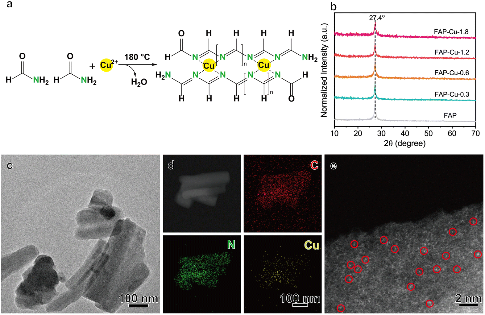 | ||
| Fig. 1 (a) A schematic illustration of the synthesis of a single-atom Cu catalyst supported on a formamide polymer. (b) XRD patterns of the FAP and FAP–Cu-x catalysts. (c–e) TEM image (c); EDS elemental mapping images of C, N and Cu elements (d); and aberration-corrected HAADF-STEM image (e) of the FAP–Cu-0.6 sample. | ||
To affirm the status of the FAP substrate, we first immersed the representative FAP–Cu-0.6 sample into the aqua regia solution. Although the sample is initially similar to carbon black, it decomposes completely after 24 h, while carbon black is unaltered (Fig. S1†). The dissolution of FAP–Cu-0.6 is derived from the reversible Schiff base reaction, wherein the CN bond in the FAP is hydrolyzed back to the amino and aldehyde groups under robust acidic conditions. In contrast, the chemically stable C–C bond in carbon black can hardly be broken. This phenomenon proves that formamide undergoes polycondensation rather than carbonization during the solvothermal process. The characteristics of the polycondensation products are also confirmed by Fourier transform infrared (FTIR) spectroscopy. As shown in Fig. S2,† two IR characteristic signals at 1395 and 1610 cm−1 correspond to the C–N and CN bonds, respectively,20 which is consistent with the functional groups in FAP.
The as-synthesized FAP–Cu-x samples were examined using X-ray diffraction (XRD). The related patterns (Fig. 1b) show that there is only a diffraction peak at 27.4°, corresponding to the (002) peak of the carbon nitride phase.23 Transmission electron microscopy (TEM) and scanning electron microscopy (SEM) images of FAP–Cu-x samples (Fig. 1c and Fig. S3–S5†) show irregular rod-like morphology with a size of hundreds of nanometers. Taking FAP–Cu-0.6 as a representative, the elemental energy-dispersive X-ray spectroscopy (EDS) mapping analysis illustrates the homogeneous dispersion of the C, N, and Cu elements (Fig. 1d). A high-resolution transmission electron microscopy (HRTEM) image excludes the existence of crystalline or aggregated Cu species in FAP–Cu-0.6 (Fig. S3b†). The HRTEM measurements together with XRD patterns reveal the absence of metallic Cu and Cu-based compound phases, suggesting that the Cu species are highly dispersed on the formamide polymer substrate. As further consolidated by aberration-corrected high-angle annular dark-field scanning transmission electron microscopy (HAADF-STEM) characterization, the bright dots depicted in Fig. 1e are scatteredly distributed in the FAP host, indicating the presence of isolated Cu atoms. Additionally, we conducted the N2 sorption measurements to reveal the pore distribution, whose desorption curve almost coincided with the adsorption counterpart (Fig. S6†). The BET surface areas are determined as 16.154 and 18.552 m2 g−1 for FAP and FAP–Cu-0.6, respectively. These results demonstrate that the polymerization process of FAP does not yield a porous structure.
The electronic states of the elements were then checked using X-ray photoelectron spectroscopy (XPS). Fig. 2a and b display the high-resolution C 1s and N 1s core-level spectra, respectively. In particular, the deconvoluted peaks at binding energies (BEs) of 285.7, 286.5 and 287.9 eV in the C 1s spectra can be assigned to the C–N, CN and CO groups, respectively (Fig. 2a),24,25 while the ones at BEs of 398.9 and 400.3 eV in the N 1s spectra correspond to the CN and –NH2 groups (Fig. 2b),25,26 respectively. X-ray absorption spectroscopy (XAS) is further used to explore the microstructure of FAP and FAP–Cu-0.6. The C K-edge spectra show a broad absorption ranging from 285 to 290 eV with a peak centered at 288.2 eV (Fig. 2c), which can be assigned to CN–C resonance.27,28 This CN–C motif is also evidenced in the N K-edge spectra (Fig. 2d), whose peak is located at 399.6 eV.27 The structural characterizations of dominant C–N bonding affirm again the polycondensation of FAP substrate. Additionally, the enhanced absorption peak of FAP–Cu-0.6 in the normalized N K-edge spectra compared to that in C K-edge spectra confirms the regulated electronic states of the N element after Cu introduction, suggesting that Cu atoms coordinate with N atoms rather than C atoms in the FAP substrate. In the meantime, the electronic states and coordination structure of the Cu element are determined by synchrotron-based X-ray absorption fine spectroscopy (XAFS). In Cu K-edge X-ray near-edge fine structure spectroscopy (XANES, see Fig. 2e), it is recognized that the white-line peak of FAP–Cu-0.6 (8996.2 eV) is located between Cu2O (8995.3 eV) and CuO (8997.3 eV), and its absorption edge is also between the Cu2O and CuO references. This observation indicates that the valence state of Cu species in the FAP–Cu-0.6 sample is Cuδ+ (1 < δ < 2). The k2-weighted Fourier-transformed extended XAFS (FT-EXAFS) demonstrates the dominant peak with a radial distance of 1.47 Å (without phase shift), attributed to the Cu–N/C scattering path. It is noteworthy that no metallic Cu–Cu bond with a scattering path at around 2.24 Å or larger bond distances is detected, indicating the single-atom state of Cu species in FAP substrate even the Cu loading amount as high as 5.87 wt%. According to the Cu K-edge EXAFS fitting results (Table S2†), the coordination numbers of the Cu–N/C bonds are about 4.4. Given the stronger interaction between Cu and N, it is surmised that one Cu atom coordinates with four N ligands to form the CuN4 motif in the FAP matrix, as demonstrated in Fig. 1a.
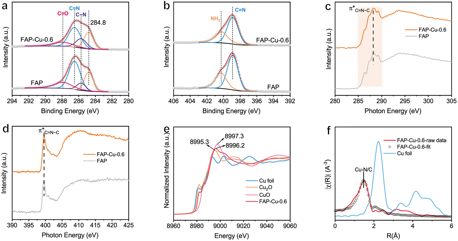 | ||
| Fig. 2 (a) C 1s and (b) N 1s XPS spectra of FAP and FAP–Cu-0.6. (c) C K-edge and (d) N K-edge XAS spectra of FAP and FAP–Cu-0.6. (e) Cu K-edge XANES spectra and (f) the k2-weighted FT-EXAFS spectra of FAP–Cu-0.6. | ||
Upon acquiring structural information for the single-atom Cu catalyst supported on the FAP substrate, the electrochemical CO2RR performance was evaluated in a flow cell using 1 M KOH as an electrolyte (see details in the Experimental section). The corresponding linear sweep voltammetry (LSV) curves for the FAP and FAP–Cu-0.6 catalysts are shown in Fig. S7.† The onset potential of CO2RR is earlier than that of the hydrogen evolution reaction (HER), and the current density of FAP–Cu-0.6 in a CO2 atmosphere increases slower than that in an Ar atmosphere, suggesting that HER is effectively restrained on the surface of the FAP–Cu-0.6 catalyst. In addition, the charge transfer resistance is reduced by increasing Cu content according to electrochemical impedance spectroscopy (EIS) measurement (Fig. S8†), indicating the accelerated interfacial charge transfer to trigger the effective CO2RR. The electrochemical CO2RR performance was further assessed at different applied current densities. The FE distribution of all products of each catalyst is shown in Fig. 3a–c and Fig. S9,† and the total FEs are determined to be near 100%. The bare FAP catalyst produces only H2; basically, no products of CO2RR are detected (Fig. 3b and S9a†). In sharp contrast, FAP–Cu-x catalysts with anchored Cu single atom species can effectively trigger the CO2RR with CH4 as the main product (Fig. S9b–S9e†). The production of H2 is gradually limited when more Cu is loaded onto the FAP, and the H2 FE is reduced to less than 20% for the FAP–Cu-1.2 catalyst (Fig. 3b). In terms of CO2RR, there is an optimal Cu loading amount in the catalysts for CH4 production. As compared in Fig. 3a, FAP–Cu-1.2 exhibits the best CH4 production performance among our catalysts. As the Cu amount continues to increase for the FAP–Cu-1.8 catalyst, more CO and C2H4 by-products are obtained (Fig. 3c and S9f†), thus decreasing the selectivity of the desired CH4 product. The reduced CH4 production activity of the FAP–Cu-1.8 catalyst is mainly attributed to the Cu aggregation for high loading amounts, especially in reductive operating conditions. It is noteworthy that although the Cu amount in the FAP–Cu-1.2 catalyst (10.59 wt%) is nearly twice that of the FAP–Cu-0.6 counterpart (5.87 wt%), their electrochemical performance for CO2RR is almost comparable in terms of both selectivity and activity (i.e., FE and partial current density for CH4, see Fig. 3a and d, respectively). Specifically, in the current density ranging from 100 to 600 mA cm−2, both of them can achieve the CH4 Fes of over 60%. For the FAP–Cu-1.2 catalyst, a CH4 partial current density of 407.4 mA cm−2 is obtained at a total current density of 600 mA cm−2, while the FAP–Cu-0.6 catalyst can also exhibit a maximum CH4 partial current density of 376.4 mA cm−2 under the same operating conditions (Fig. 3d).
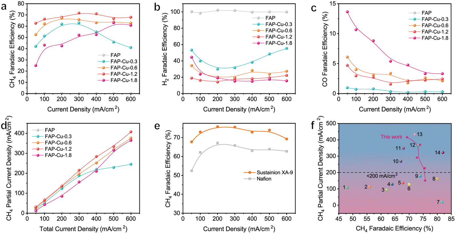 | ||
| Fig. 3 (a–c) The determined FEs of (a) CH4, (b) H2 and (c) CO products over various catalysts. (d) The calculated CH4 partial current densities over various catalysts. (e) CH4 FE values with different binders. (f) Comparison of the CH4 partial current densities and FEs of our optimized FAP–Cu-0.6 catalyst with those of other recently reported electrocatalyst for CO2-to-CH4 conversion (the catalyst references are labelled as 1 of Sputter Cu on PTFE,29 2 of 7% Au–Cu,30 3 of Cu/Al2O3,31 4 of CuFe–SA,32 5 of Cu–Ce–Ox,33 6 of Cu–TDPP–NS,34 7 of Cu clusters/DRC,35 8 of Cu–DBC,36 9 of Ag@Cu2O,37 10 of CeO2 cluster-7% Cu,38 11 of Cu PTI,39 12 of carbon coated on Cu/Cu2O,40 13 of 20%Cu/MgSiO341 and 14 of NNU-33(H)42). | ||
Activity stability is also a crucial parameter for catalyst assessment. Previous studies have indicated that the structure of a catalyst may be chemically unstable under electrocatalytic conditions when the Cu loading amount is too high.38 In this regard, we investigated the stability matter of FAP–Cu-0.6 and FAP–Cu-1.2 catalysts. The GDE coated with the catalyst was used for two continuous chronoamperometric electrolysis at 300 mA cm−2. For the FAP–Cu-1.2 catalyst, the CH4 FE apparently decreases to 42.7% during the second electrolysis process with respect to the initial 65.2%, together with the increasing generation of CO and C2H4 by-products (Fig. S10a†). This implies that the structure of the FAP–Cu-1.2 catalyst is unstable during long-term electrolysis. We rationalize such an activity change as the dynamic agglomeration of Cu species, similar to FAP–Cu-1.8. In comparison, the FAP–Cu-0.6 catalyst with a lower Cu amount exhibits good stability with a similar product distribution during the two electrolyses, still retaining the FE of CH4 up to 62.3% (Fig. S10b†). Structural measurements using TEM, SEM and XRD characterizations show that the FAP–Cu-0.6 catalyst does not undergo a significant structural change, and Cu single atom species is well kept after electrocatalytic reaction (Fig. S11–S13†). Considering the catalytic activity, stability and atomic economy together, we propose that FAP–Cu-0.6 is the optimized CO2RR catalyst in our study.
Upon the evaluated catalytic performance, the electrochemical CO2RR process was also monitored by electrochemical in situ synchrotron-radiation Fourier transform infrared (SR-FTIR) spectroscopy (Fig. S14†). Bare FAP does not show recognizable intermediate signals for CO2RR during the test (Fig. S14a†), which agrees with the electrocatalytic results that the FAP catalyst can only produce hydrogen. For FAP–Cu-0.6, two distinct fingerprint signals of CO2RR intermediates are observed in the collected spectra (Fig. S14b†), including the peaks at 1250 cm−1 attributed to *COOH,43 and 1174 cm−1 assigned to *CH3O species.44,45 In fact, the reaction path of CO2-to-CH4 conversion has been well proposed as the stepwise hydrogenation–deoxygenation process of CO2 → *COOH → *CO → *CHO → *CH2O → *CH3O → CH4.31,46,47 The two intermediates recognized by in situ SR-FTIR spectroscopy are consistent with this pathway, suggesting that the electroreduction of CO2 to CH4 on the surface of FAP–Cu-0.6 catalyst also follows this recognized reaction mechanism. In addition, the single-atom state of Cu active sites prevents C–C coupling to avoid the formation of undesired C2+ products.
The binder used during the catalyst ink preparation can also play a vital role in the electrochemical CO2RR process by altering the local hydrophobicity/hydrophily and conducting electricity.48 As confirmed, when we replaced the typical Nafion binder with the Sustainion XA-9 ionomer, the CH4 FE was significantly improved together with further reduction in H2 production (Fig. 3e and S15a†). In the wide current density ranging from 100 to 600 mA cm−2, the FAP–Cu-0.6 catalyst achieves the CH4 FEs to be more than 70% with a maximum value of 75.7% at 200 mA cm−2. A maximum CH4 partial current density of 415.8 mA cm−2 is therefore obtained (Fig. S15b†). Given the high activity and selectivity of CH4 production, the related cathodic energy efficiency (CEECH4) was calculated (Fig. S16†), wherein a maximum value of up to 36.4% is achieved at the current density of 200 mA cm−2. The improved CO2RR performance might be attributed to the difference in the microenvironment after changing the binder because Nafion and Sustainion XA-9 ionomers exhibit the conducting electricity through different ions owing to their different chemical structures (Fig. S17†). In addition, it has been widely investigated that the microenvironment of catalysts greatly influences product distribution.49,50 The Sustainion XA-9 ionomer could elevate the local CO2/H2O ratio with respect to the Nafion ionomer owing to its hydrophobic feature, which efficiently inhibits HER. Thus, the activity of CO2RR can be further improved when using Sustainion XA-9 as the binder.51 Consequently, our optimal FAP–Cu-0.6 catalyst advance exhibits a fascinating and competitive performance toward electrocatalytic CO2-to-CH4 conversion compared to other recently reported CO2RR electrocatalyst candidates, as illustrated in Fig. 3f and Table S3.†
As is well known, severe flooding of the GDE occurs during electrolysis in the conventional flow cells for CO2RR, leading to significant activity bleaching. The membrane electrode assembly (MEA) electrolyzer does not require the use of a cathode electrolyte, thus largely alleviating the dilemma caused by flooding. Therefore, the FAP–Cu-0.6 catalyst was encapsulated into the MEA electrolyzer (Fig. 4a) to assess the CO2RR performance. Fig. 4b shows the current densities as a function of applied cell potentials, which are determined to be 277.2 mA cm−2 at 4.3 V. Considering the active area of the GDE of 4 cm2, the total reaction current can reach 1.1 A. The CH4 FEs in the MEA electrolyzer are similar to those in the flow cell (Fig. 4c), exceeding 70% in the cell potential ranging from 3.9 to 4.3 V with the highest value of 74.2% at 4.1 V. Stability was also evaluated by carrying out continuous chronoamperometric electrolysis at a cell potential of 3.8 V without periodic refreshing treatment. The reaction current remains relatively stable throughout the overall electrolysis process (Fig. 4d). Inspiringly, the electrolysis durability is apparently improved with the retained CH4 FE over 50% after a long-term 13 h test. The gradual decrease in CH4 production is still derived from the flooding of salt deposition in the MEA electrolyzer (Fig. S18†), yet it has been largely alleviated compared to a flow cell.
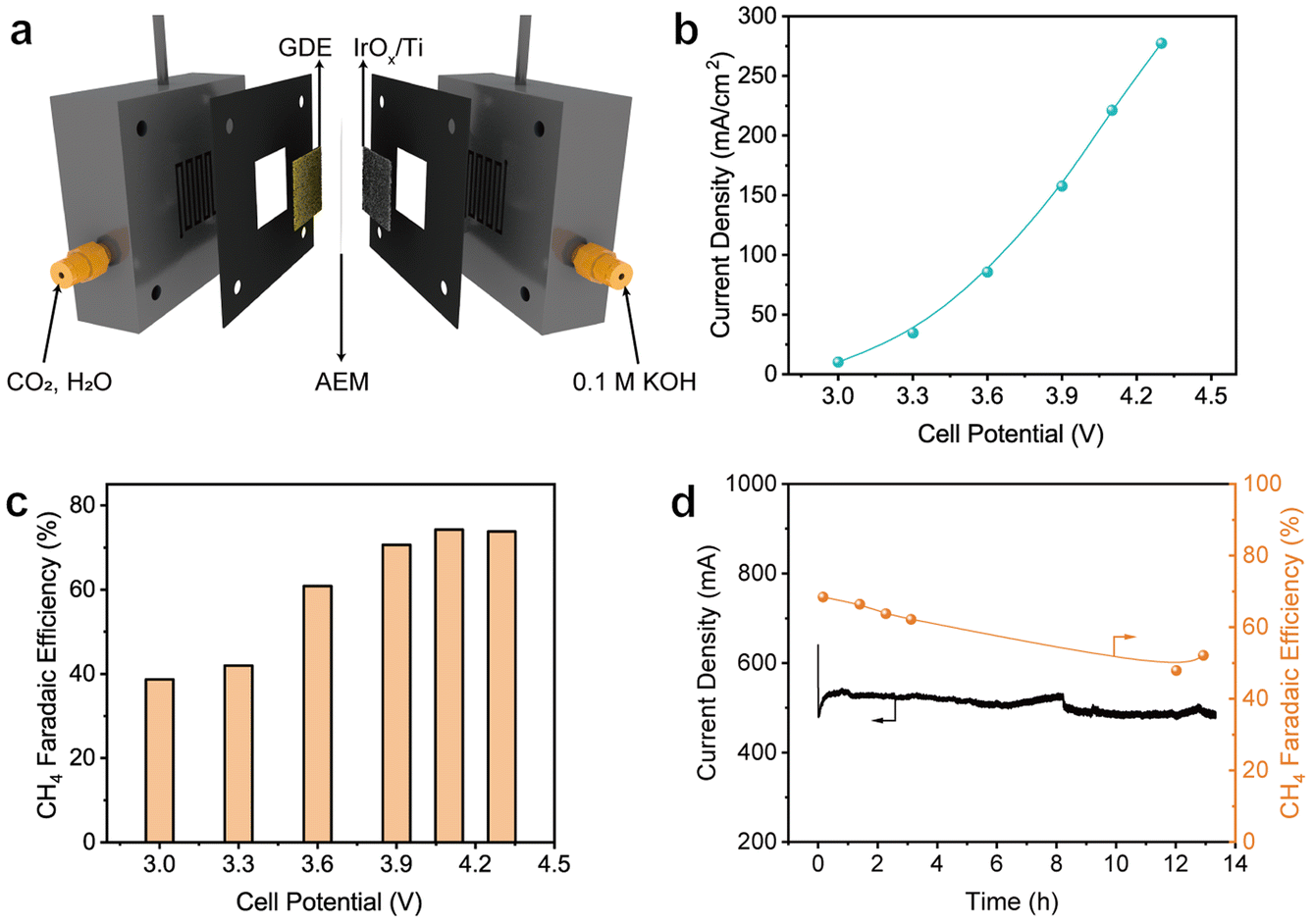 | ||
| Fig. 4 (a) A schematic illustration of the MEA electrolyzer. (b) Current densities and (c) related CH4 FEs in the MEA electrolyzer under different cell potentials over the FAP–Cu-0.6 catalyst. (d) The chronoamperometric stability test for the MEA electrolyzer. | ||
4. Conclusions
In summary, we synthesized single-atom Cu catalysts anchored on a formamide polymer substrate through the polycondensation reaction for electrocatalytic CO2RR to CH4. Owing to the high content of nitrogen ligands in the formamide polymer host, the loading amount of Cu species is highly controllable while retaining single atom states. Consequently, the optimal catalyst with a Cu loading amount of 5.87 wt% (FAP–Cu-0.6) exhibits high CH4 FEs of more than 70% in the wide current density ranging from 100 to 600 mA cm−2 in the CO2RR flow cell, offering the maximum CH4 partial current density as high as 415.8 mA cm−2. When used in the MEA electrolyzer, the FAP–Cu-0.6 catalyst achieves the CH4 FE of up to 74.2% under the optimized conditions and retains an FE of more than 50% for a long-term 13 h durability test. This study provides an innovative strategy for rationally constructing high-loading and well-dispersed single-atom Cu catalysts and emphasizes the importance of electrolytic reaction apparatus design for electrocatalytic CO2 reduction reactions.Author contributions
Jiawei Li and Yawen Jiang: conceptualization, investigation, formal analysis and writing original draft. Jiayi Li and Xinyu Wang: formal analysis. Ning Zhang, Ran Long and Yujie Xiong: supervision, writing review & editing, project administration and funding acquisition.Conflicts of interest
There are no conflicts to declare.Acknowledgements
This work was financially supported in part by the National Key R&D Program of China (2020YFA0406103), NSFC (22232003, 22305243, 22122506, 22075267, 21725102, 91961106), the CAS Hundred Talent Program, Anhui Provincial Natural Science Foundation (2008085J05), Jiangsu Provincial Natural Science Foundation (BK20230272), the Open Funding Project of National Key Laboratory of Human Factors Engineering (SYFD062010K), and Fundamental Research Funds for the Central Universities (20720220007, KY2140000031, WK2060000039). Cu K-edge XAFS characterization was performed at the beamline BL14W1 in the Shanghai Synchrotron Radiation Facility (SSRF), China. XAS characterizations and in situ SR-FTIR measurements were performed at the beamlines MCD-A and MCD-B (Soochow Beamline for Energy Materials) and beamline BL01B, respectively, in the National Synchrotron Radiation Laboratory (NSRL), China. The authors thank the support from USTC Center for Micro- and Nanoscale Research and Fabrication.References
- M. Mikkelsen, M. Jørgensen and F. C. Krebs, Energy Environ. Sci., 2010, 3, 43–81 RSC.
- S. Nitopi, E. Bertheussen, S. B. Scott, X. Liu, A. K. Engstfeld, S. Horch, B. Seger, I. E. L. Stephens, K. Chan, C. Hahn, J. K. Norskov, T. F. Jaramillo and I. Chorkendorff, Chem. Rev., 2019, 119, 7610–7672 CrossRef CAS PubMed.
- A. Caballero and P. J. Pérez, Chem. Soc. Rev., 2013, 42, 8809–8820 RSC.
- M. Younas, L. L. Kong, M. J. K. Bashir, H. Nadeem, A. Shehzad and S. Sethupathi, Energy Fuels, 2016, 30, 8815–8831 CrossRef CAS.
- Y. Zhang, J. Gui, D. Wang, J. Mao, C. Zhang and F. Li, Nanoscale, 2023, 15, 1092–1098 RSC.
- Q. Zhu, Y. Hu, H. Chen, C. Meng, Y. Shang, C. Hao, S. Wei, Z. Wang, X. Lu and S. Liu, Nanoscale, 2023, 15, 2106–2113 RSC.
- Y. Dai, H. Li, C. Wang, W. Xue, M. Zhang, D. Zhao, J. Xue, J. Li, L. Luo, C. Liu, X. Li, P. Cui, Q. Jiang, T. Zheng, S. Gu, Y. Zhang, J. Xiao, C. Xia and J. Zeng, Nat. Commun., 2023, 14, 3382 CrossRef CAS PubMed.
- H. Fei, J. Dong, Y. Feng, C. S. Allen, C. Wan, B. Volosskiy, M. Li, Z. Zhao, Y. Wang, H. Sun, P. An, W. Chen, Z. Guo, C. Lee, D. Chen, I. Shakir, M. Liu, T. Hu, Y. Li, A. I. Kirkland, X. Duan and Y. Huang, Nat. Catal., 2018, 1, 63–72 CrossRef CAS.
- Y. Qu, Z. Li, W. Chen, Y. Lin, T. Yuan, Z. Yang, C. Zhao, J. Wang, C. Zhao, X. Wang, F. Zhou, Z. Zhuang, Y. Wu and Y. Li, Nat. Catal., 2018, 1, 781–786 CrossRef CAS.
- L. Liu and A. Corma, Chem. Rev., 2018, 118, 4981–5079 CrossRef CAS PubMed.
- S. Li, C. Cheng, X. Zhao, J. Schmidt and A. Thomas, Angew. Chem., Int. Ed., 2018, 57, 1856–1862 CrossRef CAS PubMed.
- Q. Li, W. Chen, H. Xiao, Y. Gong, Z. Li, L. Zheng, X. Zheng, W. Yan, W.-C. Cheong, R. Shen, N. Fu, L. Gu, Z. Zhuang, C. Chen, D. Wang, Q. Peng, J. Li and Y. Li, Adv. Mater., 2018, 30, 1800588 CrossRef PubMed.
- Z.-Y. Wu, P. Zhu, D. A. Cullen, Y. Hu, Q.-Q. Yan, S.-C. Shen, F.-Y. Chen, H. Yu, M. Shakouri, J. D. Arregui-Mena, A. Ziabari, A. R. Paterson, H.-W. Liang and H. Wang, Nat. Synth., 2022, 1, 658–667 CrossRef.
- Y. Pan, S. Liu, K. Sun, X. Chen, B. Wang, K. Wu, X. Cao, W.-C. Cheong, R. Shen, A. Han, Z. Chen, L. Zheng, J. Luo, Y. Lin, Y. Liu, D. Wang, Q. Peng, Q. Zhang, C. Chen and Y. Li, Angew. Chem., Int. Ed., 2018, 57, 8614–8618 CrossRef CAS PubMed.
- H.-W. Liang, W. Wei, Z.-S. Wu, X. Feng and K. Müllen, J. Am. Chem. Soc., 2013, 135, 16002–16005 CrossRef CAS PubMed.
- C. Xia, Y. Qiu, Y. Xia, P. Zhu, G. King, X. Zhang, Z. Wu, J. Y. Kim, D. A. Cullen, D. Zheng, P. Li, M. Shakouri, E. Heredia, P. Cui, H. N. Alshareef, Y. Hu and H. Wang, Nat. Chem., 2021, 13, 887–894 CrossRef CAS PubMed.
- X. Wang, Y. Fei, J. Chen, Y. Pan, W. Yuan, L. Y. Zhang, C. X. Guo and C. M. Li, Small, 2021, 18, 2103866 CrossRef PubMed.
- X. Song, S. Chen, L. Guo, Y. Sun, X. Li, X. Cao, Z. Wang, J. Sun, C. Lin and Y. Wang, Adv. Energy Mater., 2018, 8, 1801101 CrossRef.
- X. Fan, M. Zhao, T. Li, L. Y. Zhang, M. Jing, W. Yuan and C. M. Li, Nanoscale, 2021, 13, 18332–18339 RSC.
- G. Zhang, Y. Jia, C. Zhang, X. Xiong, K. Sun, R. Chen, W. Chen, Y. Kuang, L. Zheng, H. Tang, W. Liu, J. Liu, X. Sun, W.-F. Lin and H. Dai, Energy Environ. Sci., 2019, 12, 1317–1325 RSC.
- J. L. de la Fuente, M. Ruiz-Bermejo, C. Menor-Salván and S. Osuna-Esteban, Polym. Degrad. Stab., 2011, 96, 943–948 CrossRef CAS.
- Z. Gong, B. Yang, H. Lin, Y. Tang, Z. Tang, J. Zhang, H. Zhang, Y. Li, Y. Xie, Q. Li and L. Chi, ACS Nano, 2016, 10, 4228–4235 CrossRef CAS PubMed.
- Z. Chen, S. Mitchell, E. Vorobyeva, R. K. Leary, R. Hauert, T. Furnival, Q. M. Ramasse, J. M. Thomas, P. A. Midgley, D. Dontsova, M. Antonietti, S. Pogodin, N. López and J. Pérez-Ramírez, Adv. Funct. Mater., 2017, 27, 1605785 CrossRef.
- B. Zhang, J. Yan, G. Li and Z. Wang, Polym. Chem., 2019, 10, 3371–3379 RSC.
- H. Liu, X. Lv, J. Qian, H. Li, Y. Qian, X. Wang, X. Meng, W. Lin and H. Wang, ACS Nano, 2020, 14, 13304–13315 CrossRef CAS PubMed.
- Y. Zhao, X. Liu and Y. Han, RSC Adv., 2015, 5, 30310–30330 RSC.
- Y. Zheng, Y. Jiao, Y. Zhu, L. H. Li, Y. Han, Y. Chen, A. Du, M. Jaroniec and S. Z. Qiao, Nat. Commun., 2014, 5, 3783 CrossRef PubMed.
- Y. Xu, C. Qiu, X. Fan, Y. Xiao, G. Zhang, K. Yu, H. Ju, X. Ling, Y. Zhu and C. Su, Appl. Catal., B, 2020, 268, 118457 CrossRef CAS.
- X. Wang, A. Xu, F. Li, S.-F. Hung, D.-H. Nam, C. M. Gabardo, Z. Wang, Y. Xu, A. Ozden, A. S. Rasouli, A. H. Ip, D. Sinton and E. H. Sargent, J. Am. Chem. Soc., 2020, 142, 3525–3531 CrossRef CAS PubMed.
- X. Wang, P. Ou, J. Wicks, Y. Xie, Y. Wang, J. Li, J. Tam, D. Ren, J. Y. Howe, Z. Wang, A. Ozden, Y. Z. Finfrock, Y. Xu, Y. Li, A. S. Rasouli, K. Bertens, A. H. Ip, M. Graetzel, D. Sinton and E. H. Sargent, Nat. Commun., 2021, 12, 3387 CrossRef CAS PubMed.
- S. Chen, B. Wang, J. Zhu, L. Wang, H. Ou, Z. Zhang, X. Liang, L. Zheng, L. Zhou, Y.-Q. Su, D. Wang and Y. Li, Nano Lett., 2021, 21, 7325–7331 CrossRef CAS PubMed.
- S.-F. Hung, A. Xu, X. Wang, F. Li, S.-H. Hsu, Y. Li, J. Wicks, E. G. Cervantes, A. S. Rasouli, Y. C. Li, M. Luo, D.-H. Nam, N. Wang, T. Peng, Y. Yan, G. Lee and E. H. Sargent, Nat. Commun., 2022, 13, 819 CrossRef CAS PubMed.
- X. Zhou, J. Shan, L. Chen, B. Y. Xia, T. Ling, J. Duan, Y. Jiao, Y. Zheng and S.-Z. Qiao, J. Am. Chem. Soc., 2022, 144, 2079–2084 CrossRef CAS PubMed.
- Y. R. Wang, M. Liu, G. K. Gao, Y. L. Yang, R. X. Yang, H. M. Ding, Y. Chen, S. L. Li and Y. Q. Lan, Angew. Chem., Int. Ed., 2021, 60, 21952–21958 CrossRef CAS PubMed.
- Q. Hu, Z. Han, X. Wang, G. Li, Z. Wang, X. Huang, H. Yang, X. Ren, Q. Zhang, J. Liu and C. He, Angew. Chem., Int. Ed., 2020, 59, 19054–19059 CrossRef CAS PubMed.
- Y. Zhang, L.-Z. Dong, S. Li, X. Huang, J.-N. Chang, J.-H. Wang, J. Zhou, S.-L. Li and Y.-Q. Lan, Nat. Commun., 2021, 12, 6390 CrossRef CAS PubMed.
- L. Xiong, X. Zhang, L. Chen, Z. Deng, S. Han, Y. Chen, J. Zhong, H. Sun, Y. Lian, B. Yang, X. Yuan, H. Yu, Y. Liu, X. Yang, J. Guo, M. H. Rümmeli, Y. Jiao and Y. Peng, Adv. Mater., 2021, 33, 2101741 CrossRef CAS PubMed.
- Y. Jiang, K. Mao, J. Li, D. Duan, J. Li, X. Wang, Y. Zhong, C. Zhang, H. Liu, W. Gong, R. Long and Y. Xiong, ACS Nano, 2023, 17, 2620–2628 CrossRef CAS PubMed.
- S. Roy, Z. Li, Z. Chen, A. C. Mata, P. Kumar, S. C. Sarma, I. F. Teixeira, I. F. Silva, G. Gao, N. V. Tarakina, M. G. Kibria, C. V. Singh, J. Wu and P. M. Ajayan, Adv. Mater., 2023 DOI:10.1002/adma.202300713.
- X. Y. Zhang, W. J. Li, X. F. Wu, Y. W. Liu, J. Chen, M. Zhu, H. Y. Yuan, S. Dai, H. F. Wang, Z. Jiang, P. F. Liu and H. G. Yang, Energy Environ. Sci., 2022, 15, 234–243 RSC.
- Y. Zhong, J. Low, Q. Zhu, Y. Jiang, X. Yu, X. Wang, F. Zhang, W. Shang, R. Long, Y. Yao, W. Yao, J. Jiang, Y. Luo, W. Wang, J. Yang, Z. Zou and Y. Xiong, Natl. Sci. Rev., 2023, 10, nwac200 CrossRef CAS PubMed.
- L. Zhang, X.-X. Li, Z.-L. Lang, Y. Liu, J. Liu, L. Yuan, W.-Y. Lu, Y.-S. Xia, L.-Z. Dong, D.-Q. Yuan and Y.-Q. Lan, J. Am. Chem. Soc., 2021, 143, 3808–3816 CrossRef CAS PubMed.
- L. Xue, C. Zhang, J. Wu, Q.-Y. Fan, Y. Liu, Y. Wu, J. Li, H. Zhang, F. Liu and S. Zeng, Appl. Catal., B, 2022, 304, 120951 CrossRef CAS.
- M. Zheng, P. Wang, X. Zhi, K. Yang, Y. Jiao, J. Duan, Y. Zheng and S.-Z. Qiao, J. Am. Chem. Soc., 2022, 144, 14936–14944 CrossRef CAS PubMed.
- X. Li, Y. Sun, J. Xu, Y. Shao, J. Wu, X. Xu, Y. Pan, H. Ju, J. Zhu and Y. Xie, Nat. Energy, 2019, 4, 690–699 CrossRef CAS.
- G. Wang, J. Chen, Y. Ding, P. Cai, L. Yi, Y. Li, C. Tu, Y. Hou, Z. Wen and L. Dai, Chem. Soc. Rev., 2021, 50, 4993–5061 RSC.
- S. Chen, W.-H. Li, W. Jiang, J. Yang, J. Zhu, L. Wang, H. Ou, Z. Zhuang, M. Chen, X. Sun, D. Wang and Y. Li, Angew. Chem., Int. Ed., 2022, 61, e2021144 Search PubMed.
- T. H. M. Pham, J. Zhang, M. Li, T. H. Shen, Y. Ko, V. Tileli, W. Luo and A. Züttel, Adv. Energy Mater., 2022, 12, 2103663 CrossRef CAS.
- F. Li, A. Thevenon, A. Rosas-Hernández, Z. Wang, Y. Li, C. M. Gabardo, A. Ozden, C. T. Dinh, J. Li, Y. Wang, J. P. Edwards, Y. Xu, C. McCallum, L. Tao, Z.-Q. Liang, M. Luo, X. Wang, H. Li, C. P. O'Brien, C.-S. Tan, D.-H. Nam, R. Quintero-Bermudez, T.-T. Zhuang, Y. C. Li, Z. Han, R. D. Britt, D. Sinton, T. Agapie, J. C. Peters and E. H. Sargent, Nature, 2020, 577, 509–513 CrossRef CAS PubMed.
- X. Chen, J. Chen, N. M. Alghoraibi, D. A. Henckel, R. Zhang, U. O. Nwabara, K. E. Madsen, P. J. A. Kenis, S. C. Zimmerman and A. A. Gewirth, Nat. Catal., 2021, 4, 20–27 CrossRef CAS.
- C. Kim, J. C. Bui, X. Luo, J. K. Cooper, A. Kusoglu, A. Z. Weber and A. T. Bell, Nat. Energy, 2021, 6, 1026–1034 CrossRef CAS.
Footnotes |
| † Electronic supplementary information (ESI) available. See DOI: https://doi.org/10.1039/d3nr05228a |
| ‡ These authors contributed equally to this work. |
| This journal is © The Royal Society of Chemistry 2024 |