
 Open Access Article
 This Open Access Article is licensed under a Creative Commons Attribution-Non Commercial 3.0 Unported Licence
Self-assembly of DNA parallel double-crossover motifs†
Jung Yeon
Lee
a,
Qi
Yang
a,
Xu
Chang
a,
Maciej
Jeziorek
b,
Devanathan
Perumal
a,
Tiffany R.
Olivera
a,
Jean-Pierre
Etchegaray
bc and
Fei
Zhang
 *a
*a
aDepartment of Chemistry, Rutgers University, Newark, NJ 07102, USA. E-mail: fei.zhang@rutgers.edu
bDepartment of Biological Sciences, Rutgers University, Newark, NJ 07102, USA
cRutgers Cancer Institute of New Jersey, New Brunswick, NJ 08901, USA
First published on 8th January 2024
Abstract
DNA double-crossover motifs, including parallel and antiparallel crossovers, serve as the structural foundation for the creation of diverse nanostructures and dynamic devices in DNA nanotechnology. Parallel crossover motifs have unique advantages over the widely used antiparallel crossover design but have not developed as substantially due to the difficulties in assembly. Here we created 29 designs of parallel double-crossover motifs varying in hybridization pathways, central domain lengths, and crossover locations to investigate their assembly mechanism. Arrays were successfully formed in four distinct designs, and large tubular structures were obtained in seven designs with predefined pathways and central domains appoximately 16 nucleotides in length. The nanotubes obtained from parallel crossover design showed improved nuclease resistance than the ones from the antiparallel counterpart design. Overall, our study provides a basis for the development of generalized assembly rules of DNA parallel crossover systems and opens new opportunities for their potential use in biological systems.
As an excellent biomaterial with high programmability,1 biocompatibility,2 and biodegradability,3 DNA has been used to create one-,4 two-,5 and three-dimensional6 (1D, 2D, and 3D) nanostructures. A variety of these nanostructures have been employed in different biomedical7 and biotechnological8 applications. The fundamental structures for DNA nanotechnology are the five basic DNA motifs9 that contain double crossovers to link two DNA helices, making them rigidified building blocks for nano-construction based on DNA. These five double crossover motifs were classified into two categories based on the orientation of the helices: antiparallel crossovers and parallel crossovers. To date, most design approaches in DNA nanotechnology have adopted the antiparallel design strategy in DNA self-assembly due to its simple topology and predictable assembly behaviors,9,10 as shown in tile-based lattices11 and DNA origami nanostructures.12
Although parallel-crossover motifs have been less explored, compared to antiparallel-crossover motifs, parallel-crossover motifs have begun to increasingly gain attention because of their unique beneficial properties. First, parallel-crossover motifs can be single-routed to generate single-stranded DNA and RNA nanostructures such as a 3D octahedron,6 single-stranded origami,13 and molecular knots.14 Their unique single-strand routings have allowed the self-replication of nanostructures to form via biological procedures, providing opportunities for low-cost, high-throughput production of nucleic acid nanostructures.13 The single chain routing method can also solve purity and structural integrity problems originating from missing strands during the assembly of the multiple-stranded nanostructures. Additionally, previous studies15 have demonstrated the enhancement in the nuclease resistance of parallel crossover-based tiles and nanostructures, showing their potential for biomedical applications.
All the intriguing works related to parallel crossovers16 that have been published show the promising aspects of such design in DNA nanotechnology. However, due to the unique geometry of parallel crossovers,17 it is still challenging to assemble and synthesize parallel-crossover-based nanostructures. Inspired by the previous work of parallel motifs,17 we systematically studied parallel double-crossover motifs targeting dimer-based 2D array formation by testing 29 different DNA tile designs. Here, we investigated how variations in the structural features of the monomer tiles including hybridization pathways, central domain lengths, and crossover locations influence the 2D array formation. Our research lays the groundwork for formulating general rules of design and synthesis of parallel-crossover-based nanostructures and assemblies.
First, we investigated the effect of changing hybridization pathways of one-turn double parallel-crossover (1DP) motifs on their dimer-based 2D array assembly using six sets of dimers (Fig. 1). Each 1DP motif had six domains (DNA helix segments) with varied lengths based on parallel crossover locations and contained one turn (10–11 bases) between two parallel crossovers (Fig. 1a). Each domain was color-coded according to the relative variation of the domain's melting temperature, arising from the disparities in the length and sequence of DNA strands. In the design of 1DP motifs, the length of each domain was initially altered, followed by the assignment of sequences with a percentage of GC ranging from ∼45 to ∼65%. After the sequence assignment, the shortest domain was expected to have the lowest melting temperature.
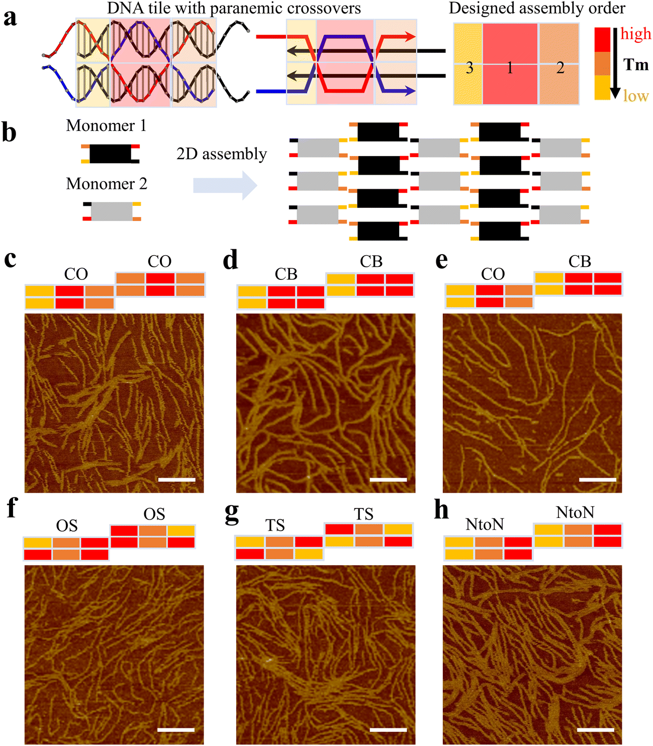 | ||
| Fig. 1 Hybridization pathways of 1DP motifs. (a) Schematics of a 1DP monomer with three-colored blocks showing relative melting temperatures. (b) A schematic of two monomers joined by sticky ends to form arrays. (c–h) AFM images showing assembled nanostructures based on 1DP motifs with different hybridization pathways. All scale bars are 100 nm. | ||
Such discrepancies in melting temperatures of different domains determine the monomer's hybridization pathway during the annealing process, where a high-to-low temperature ramp was applied to the system. For instance, in Fig. 1a, both the top and bottom mid-domains of the 1DP monomer exhibit the highest melting temperature indicated by the red colors; consequently, it is anticipated that the mid-domains will form first, followed by the formation of the outer four domains. We name this type of hybridization pathway as a center-to-out (CO) pathway (Fig. 1c). In a different design with a cooperative binding (CB) pathway (Fig. 1d), both middle and outer two domains on one side have similar melting temperatures, allowing the DNA strands in the domains to join simultaneously or cooperatively during the annealing process. For the two monomers assigned with different hybridization pathways, we name the design as the CO&CB combination pathway (Fig. 1e). The two pathways are referred to as one short arm (OS) in Fig. 1f and two short arms (TS) in Fig. 1g, respectively. In the end-to-end (NtoN) hybridization pathway (Fig. 1h), DNA strands start binding from one end to the other end according to a steady drop in the melting temperature of the domains from one side to the other. For the monomers following the same hybridization pathway, the design was simply labeled with the single pathway. In addition, to facilitate the design of different hybridization pathways in 1DP motifs, we employed the nucleic acid package (NUPACK)18 for predicting which portion of the monomer has preferential binding based on the minimum free energy and for eliminating unfavorable mismatches between DNA sequences.
Experimentally, all DNA strands of the designed 1DP monomers were purified and annealed stoichiometrically in TAE/Mg buffer. After annealing, gel electrophoresis results showed large aggregates or assembled structures smeared towards the top of gel lanes (Fig. S1–6†). Next, atomic force microscopy (AFM) was used to capture the nanoscale resolution images of the assemblies. All 1DP motifs assigned with the different hybridization pathways formed similar fibular arrays (Fig. 1c–h), rather than large planar arrays. Small portions of planar arrays were observed in Fig. 1c, d and f–h.
For 2D arrays correctly developed from DNA motifs, monomers should ideally be well-assembled, flattened, and oriented with their sticky ends pointing to the proper direction to facilitate the connection between motifs. Our observation of the preferred linear growth may be attributed to the incorrect folding or the intrinsic twisting of the 1DP monomers. The first possible scenario is that the 1DP monomers were partially formed because of topological difficulties generated from an undesirable folding pathway. Such topological difficulties are associated with the presence of an unfavorable intermediate structure that hinders the formation of the correct final target monomer structure (Fig. S7†). The second scenario is that two PXs in the 1DP motifs introduce twisting forces to the monomers in a diagonal direction (Fig. S8†). The twisted monomers then have two of their sticky ends facing away from their correct orientations, leading to the preferential formation of linear arrays rather than 2D arrays. It is also possible that both scenarios contribute to the formation of linear arrays.
Based on the assembly results of 1DP motifs, we proposed that enhancing the central binding domain of motifs would improve the proper formation of the monomer motifs and thus increase the possibility of 2D array growth. We increased the length of central segments from one turn to one and a half turns. The increase in the length of the central domains raised their melting temperatures, thus creating a larger annealing temperature difference between the formation of individual motif and the sticky-end cohesion. During the annealing process, DNA strands first assemble into monomers at high-temperature regions before growing 2D arrays at low temperature regions via sticky-end interactions between well-formed motifs. Therefore, a large temperature difference will better separate these two steps to allow longer folding time for each motif as well as to avoid undesired mismatching between sticky ends with the body domains of monomer motifs. First, we created 1.5-turn double parallel crossover (1.5DP) motifs with five hybridization pathways including NtoN, TS, OS, CO, and CB&CO combinations (Fig. 2). We followed the same design and characterization procedures as in the previous 1DP systems. As shown in Fig. 2d, e and g, three promising results from the TS, OS, and CB&CO designs produced large assemblies including partially wrapped, layered 2D arrays in TS and OS design (Fig. S11 and S12†), and nanotubes in CB&CO design (Fig. S14†), while 1.5DP designs with NtoN and CO hybridization pathways (Fig. 2b, c and f) showed fibular or linear arrays. Besides the 2D assemblies in TS and OS, another unique feature that was not observed in the previous 1DP systems was the abundant formation of sharply curved, circular nanostructures (Fig. 2d and e). The presence of small circular structures indicates that these two folding pathways, TS and OS, could exist strong twisting and/or curving forces inside the motifs or between the motifs.
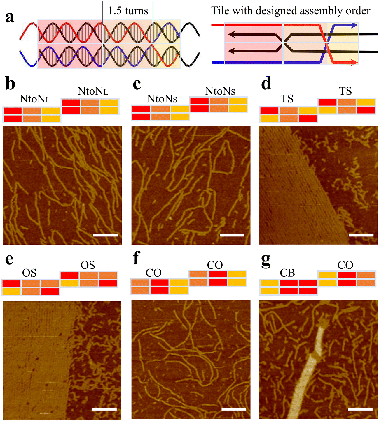 | ||
| Fig. 2 Hybridization pathways of 1.5DP motifs. (a) Schematics of a 1.5DP monomer with three-colored blocks showing relative melting temperatures. (b–g) AFM images showing assembled nanostructures based on 1.5DP motifs with different hybridization pathways. NtoNL has the same hybridization pathway as NtoNS but contains a longer ‘shortest domain’ than that of NtoNS. All scale bars are 100 nm. | ||
Encouraged by the relatively uniform tubular arrays generated in CB&CO pathway, we further explored the impact of altering the crossover distance in this design. Previously, a study of antiparallel crossover motifs19 suggested the antiparallel crossover location played a critical role in 2D assembly by tunning the twisting of DNA motifs. Other previous works underlined the importance of crossover location using cryo-EM.20 Therefore, we investigated the crossover location in the similar pathway design of 1.5DP motifs to create 2D arrays (Fig. 3a). Since we have two monomers in each 1.5DP design for 2D arrays, each monomer was designed with four types of crossover locations differing in the number of bases between the two PXs. The mid-domain between two PXs of monomer 1 contains two narrow grooves and one wide groove, leading to a smaller range of nucleotides (13–16 nt), while monomer 2 contains two wide grooves and one narrow groove, allowing 15–18 nt between crossovers. All four monomer pairs have the same sticky-end sequences, and therefore matching them between pairs generates different assemblies. Based on the combinations of 4 by 4 pairings between monomers, we assembled and characterized all 16 designs accordingly (Fig. 3b).
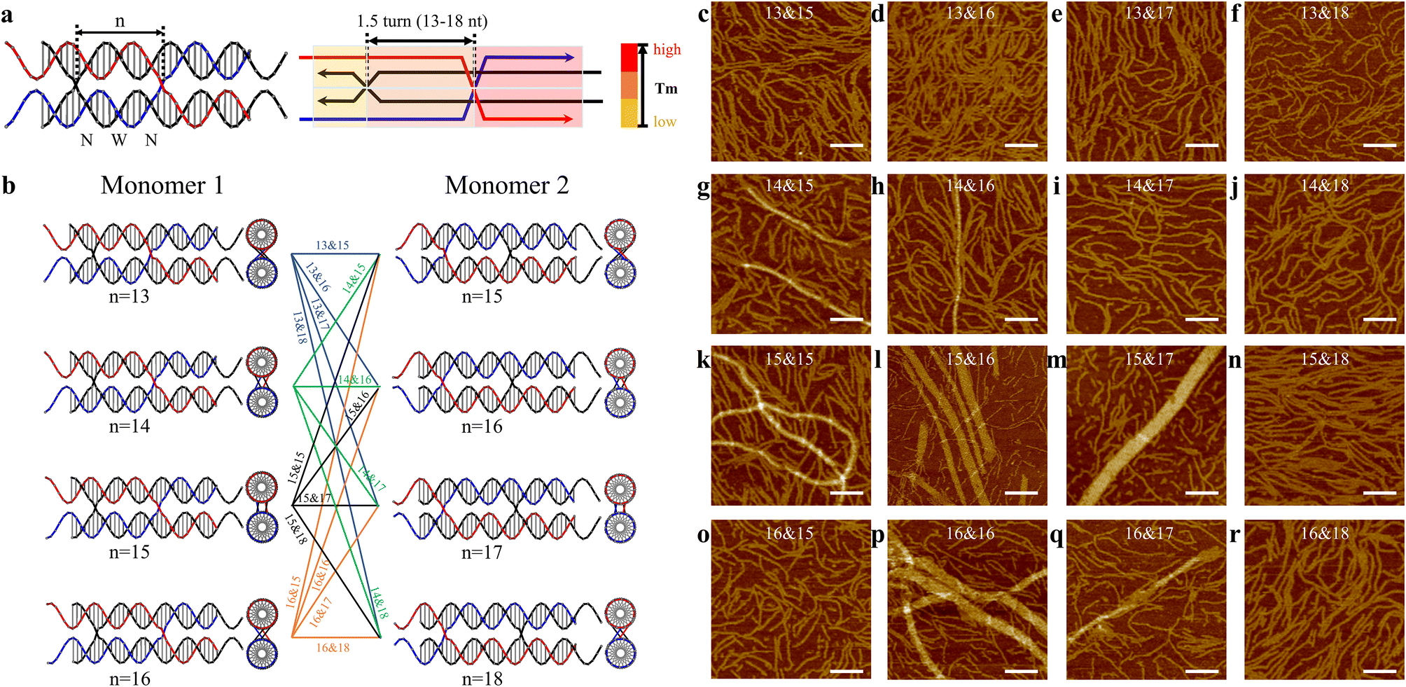 | ||
| Fig. 3 Crossover locations of 1.5DP motifs. (a) Schematics of a 1.5DP monomer, with colored blocks indicating the predefined pathway. The number n represents the number of bases between the two parallel crossovers. (b) Monomer 1 has a range of central domain lengths from 13 to 16 nt (n = 13–16), while monomer 2 has a range from 15 to 18 nt (n = 15–18). (c–r) AFM images showing assembled nanostructures from monomer pairs with different n values. All scale bars are 100 nm. | ||
In Fig. 3c–r, the 16 combinations are labeled with two numbers (e.g., 13&15) indicating the number of bases between two parallel crossovers or in the central domains of monomer 1 and monomer 2, respectively. Among the 16 designs, dominant linear assemblies were obtained in the designs with monomers having 13 or 18 bases in their central domains (Fig. 3c–f, j, n and r). 1.5 turns of B-form DNA should be close to 16 bases. In these 13/18-based designs, because the distance between the two crossovers deviates significantly from 1.5 turns, it is expected that DNA helixes between crossovers have unfavorable twists that lead to the linear array formation. Following the same rationale, we observed large tubular arrays in seven designs with combinations consisting of 14–17 nt between crossovers (Fig. 3g, h, k, l, m, p and q). Relatively wider tubes were obtained in 15&16 (max. 38.85 nm), 15&17 (max. 48.36 nm), and 16&16 (max. 65.93 nm) designs, indicating that the monomers of these combinations were close to the B-form structure of DNA with the preferred helical twisting between the 1.5-turn distanced crossovers. Interestingly, the motifs in the 16&15 design (Fig. 3o) did not produce any assembled 2D arrays. This can be explained by the different structural features in these two monomers. Monomer 2 is expected to adopt a longer distance between the two crossovers because it contains two major grooves and one minor groove, compared with monomer 1, which has two narrow grooves and one wide groove in its central domains. Therefore, the 16&15 design did not assemble into large arrays as the 15&16 design did. Furthermore, tubular formation of 2D arrays has been observed and discussed in previous studies of DNA tile assemblies using antiparallel-crossover motifs,21 agreeing with the tubular arrays assembled in our current parallel-crossover motif system. In addition, we also applied the optimal 16&16 crossover length design into the 1.5DP TS and OS motifs, which originally generated partially wrapped arrays (Fig. 2d and e). The two new designs were named TS16&16 and OS16&16 (Fig. S31 and S32†). For TS16&16 design, it was intriguing to observe the fading of the bands for self-limited structures in gels (Fig. S46†), indicating a reduced number of circular structures formed. Also, in the AFM image of TS16&16, the background was clearer than before with fewer circular structures. However, the morphology of the assembled 2D arrays did not improve or become flatter. For the OS16&16 design, the gel still exhibited the presence of the limited-sized band, consistent with the AFM data that displayed numerous circular structures in the background. The 2D assemblies were also similar with the original design (Fig. S46†).
Lastly, we investigated the nuclease resistance of a set of parallel crossover-based designs (Fig. S42 and S43†), showcasing assemblies with distinct morphologies: seven nanotubes (14&15, 14&16, 15&15, 15&16, 15&17, 16&16, and 16&17 motifs), one fibular structure (13&15 motif), and one 2D array design (1.5DP TS motif). Specifically, we also included antiparallel-crossover based arrays assembled from 1.5-turn antiparallel-crossover based 16&16 motifs, serving as the counterparts to our 1.5DP 16&16 design (Fig. S33†). As shown in Fig. 4a and d, observations revealed that the 2D TS and fibular 13&15 designs experienced significant nuclease degradation after 30 and 45 minutes, respectively (with almost no remaining large assembly bands). On the contrary, the 16&16 nanotubes still exhibited large assembly bands on top of the gel at 60 minutes and were completed digested after 120 minutes. Compared with the antiparallel counterpart of the 16&16 design, which was nearly completely degraded after 30 minutes of DNase I exposure, the parallel-crossover based 16&16 design showed improved nuclease resistance by withstanding DNase I degradation up to 1 hour. The variability in nuclease resistance based on morphology could be attributed to the different accessibility of these structures to DNase I. The nanotubes exhibited the most compact configurations with parallelly packed DNA helixes, resulting in reduced exposure to DNase I and thereby enhancing nuclease resistance. In contrast, the 2D morphology obtained from TS design (although some parts were wrapped and multi-layered) was based on 2-dimensional growth, exposing DNA helixes to nuclease digestion from all edges. Additionally, the smaller fibular structures from 13&15 displayed increased surface area due to its unwrapped configuration and thus showed less nuclease resistance than the nanotube design. In addition, we explored the concentration-dependent nuclease resistance of two distinct designs, displaying large assemblies with varied morphologies. The gel data indicated that higher concentrations generally resulted in enhanced resistance (Fig. S41†).
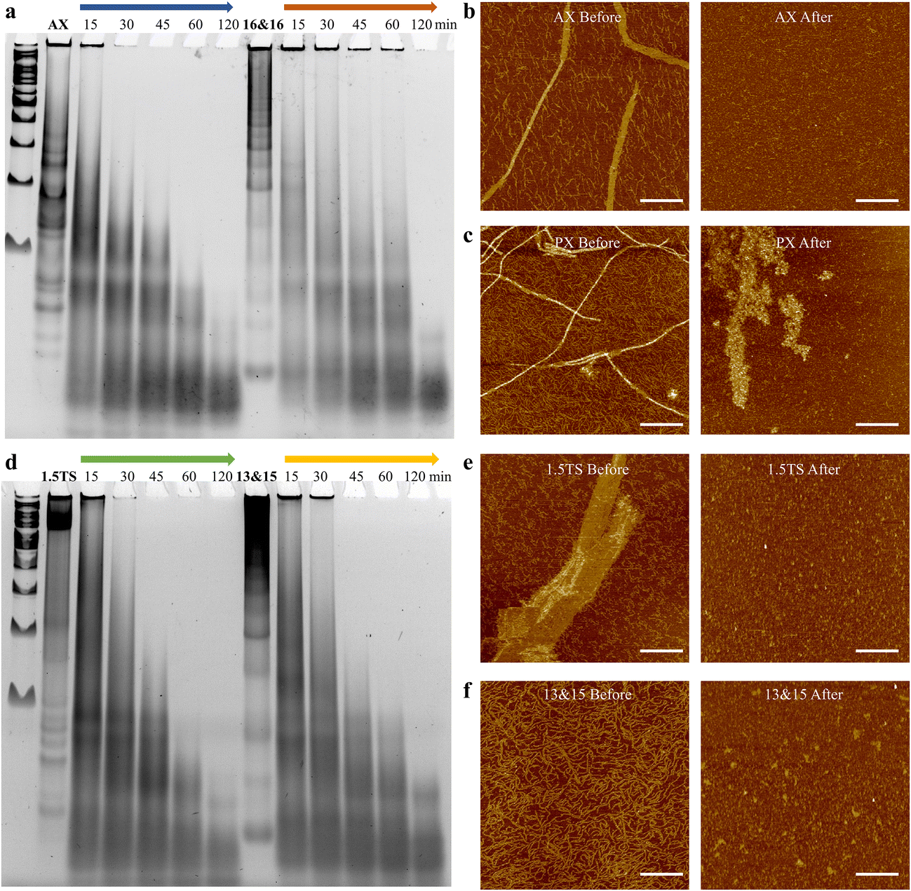 | ||
| Fig. 4 The study of 0.1 U DNase I nuclease resistance of parallel-crossover-based assemblies with different morphologies and an antiparallel nanostructure in comparison. PAGE gel result showing nuclease degradation of assembled arrays based on (a) 1.5DP motifs (16&16) and its counterpart, 1.5-turn antiparallel-crossover based motifs (16&16), and (d) 1.5DP TS (1.5TS) and 13&15 designs. AX refers to the antiparallel counterpart of the 16&16 design. AX, 16&16, 1.5TS, and 13&15 represent the original, assembled arrays without DNase I digestion. (b, c, e and f) AFM images of the corresponding arrays before and after 30 minutes of DNase I digestion. All scale bars are 600 nm. | ||
Conclusions
In summary, we systematically designed and assembled 29 parallel-crossover-based DNA dimers by programming their folding pathways, central domain lengths, and crossover locations to facilitate 2D array growth. We observed the large 2D arrays in four designs with 1.5DP OS and TS pathway designs including their 16&16 counterparts. In addition, we obtained large tubular formation in seven designs with prescribed folding pathways and 1.5-turn-long central domains and showed enhanced nuclease resistance with the parallel-crossover based arrays. For future studies, single-molecular studies are helpful to reveal the dynamics of motifs during assembly. Computational approaches can explore the impact of sequence variation of PX motifs. Furthermore, based on the result of parallel-crossover-based arrays with nuclease resistance enhancement, adding parallel-crossover element for DNA structural design generally improves the biostability for in vivo biological applications.15 Finally, our successfully formed parallel-crossover-based nanotubes may also be adopted in applications based on tubular biomaterials.22 All these efforts to study the assembly with parallel double-crossovers will help develop general rules for producing parallel-crossover-based nanostructures, allowing their future applications as biomaterials.Author contributions
J. L. and F. Z. conceived the idea. J. L. and Q. Y. designed the structures. J. L., Q. Y., and X. C. prepared the samples and characterized samples through gel and AFM. M. J. and D. P. performed fluorescence study. All authors performed the data analysis. The manuscript was written through contributions of all authors. All authors have given approval to the final version of the manuscript.Conflicts of interest
There are no conflicts to declare.Acknowledgements
This work is supported by a US National Science Foundation (NSF) Faculty Early Career Development Award (DMR-2046835), an NSF grant (CCF-2007821), a faculty Startup Fund from Rutgers University to F. Z., and NIH R21 AI167079 to J. E.References
- M. R. Jones, N. C. Seeman and C. A. Mirkin, Nanomaterials. Programmable materials and the nature of the DNA bond, Science, 2015, 347(6224), 1260901 CrossRef PubMed.
- K. E. Bujold, A. Lacroix and H. F. Sleiman, DNA Nanostructures at the Interface with Biology, Chem, 2018, 4(3), 495–521 CAS.
- D. Wang, J. Cui, M. Gan, Z. Xue, J. Wang, P. Liu, Y. Hu, Y. Pardo, S. Hamada and D. Yang, et al., Transformation of Biomass DNA into Biodegradable Materials from Gels to Plastics for Reducing Petrochemical Consumption, J. Am. Chem. Soc., 2020, 142(22), 10114–10124 CrossRef CAS PubMed.
- (a) W. Liu, X. Wang, T. Wang, R. Sha and N. C. Seeman, PX DNA triangle oligomerized using a novel three-domain motif, Nano Lett., 2008, 8(1), 317–322 CrossRef CAS PubMed; (b) Y. P. Ohayon, R. Sha, O. Flint, W. Liu, B. Chakraborty, H. K. Subramanian, J. Zheng, A. R. Chandrasekaran, H. O. Abdallah and X. Wang, et al., Covalent Linkage of One-Dimensional DNA Arrays Bonded by Paranemic Cohesion, ACS Nano, 2015, 9(10), 10304–10312 CrossRef CAS PubMed.
- P. W. Rothemund, Folding DNA to create nanoscale shapes and patterns, Nature, 2006, 440(7082), 297–302 CrossRef CAS PubMed.
- W. M. Shih, J. D. Quispe and G. F. Joyce, A 1.7-kilobase single-stranded DNA that folds into a nanoscale octahedron, Nature, 2004, 427(6975), 618–621 CrossRef CAS PubMed.
- (a) M. Chang, C. S. Yang and D. M. Huang, Aptamer-conjugated DNA icosahedral nanoparticles as a carrier of doxorubicin for cancer therapy, ACS Nano, 2011, 5(8), 6156–6163 CrossRef CAS PubMed; (b) X. Liu, Y. Xu, T. Yu, C. Clifford, Y. Liu, H. Yan and Y. Chang, A DNA nanostructure platform for directed assembly of synthetic vaccines, Nano Lett., 2012, 12(8), 4254–4259 CrossRef CAS PubMed; (c) R. Hu, X. Zhang, Z. Zhao, G. Zhu, T. Chen, T. Fu and W. Tan, DNA nanoflowers for multiplexed cellular imaging and traceable targeted drug delivery, Angew. Chem., Int. Ed., 2014, 53(23), 5821–5826 CrossRef CAS PubMed; (d) H. M. Meng, X. Zhang, Y. Lv, Z. Zhao, N. N. Wang, T. Fu, H. Fan, H. Liang, L. Qiu and G. Zhu, et al., DNA dendrimer: an efficient nanocarrier of functional nucleic acids for intracellular molecular sensing, ACS Nano, 2014, 8(6), 6171–6181 CrossRef CAS PubMed; (e) D. Jiang, Y. Sun, J. Li, Q. Li, M. Lv, B. Zhu, T. Tian, D. Cheng, J. Xia and L. Zhang, et al., Multiple-Armed Tetrahedral DNA Nanostructures for Tumor-Targeting, Dual-Modality in Vivo Imaging., ACS Appl. Mater. Interfaces, 2016, 8(7), 4378–4384 CrossRef CAS PubMed; (f) S. Li, Q. Jiang, S. Liu, Y. Zhang, Y. Tian, C. Song, J. Wang, Y. Zou, G. J. Anderson and J. Y. Han, et al., A DNA nanorobot functions as a cancer therapeutic in response to a molecular trigger in vivo, Nat. Biotechnol., 2018, 36(3), 258–264 CrossRef CAS PubMed.
- (a) R. Freeman, T. Finder and I. Willner, Multiplexed Analysis of Hg2+ and Ag+ Ions by Nucleic Acid Functionalized CdSe/ZnS Quantum Dots and Their Use for Logic Gate Operations, Angew. Chem., Int. Ed., 2009, 48(42), 7818–7821 CrossRef CAS PubMed; (b) A. Prokup, J. Hemphill and A. Deiters, DNA computation: a photochemically controlled AND gate, J. Am. Chem. Soc., 2012, 134(8), 3810–3815 CrossRef CAS PubMed.
- T. J. Fu and N. C. Seeman, DNA double-crossover molecules, Biochemistry, 1993, 32(13), 3211–3220 CrossRef CAS PubMed.
- X. Li, X. Yang, J. Qi and N. C. Seeman, Antiparallel DNA Double Crossover Molecules As Components for Nanoconstruction, J. Am. Chem. Soc., 1996, 118(26), 6131–6140 CrossRef CAS.
- H. Yan, S. H. Park, G. Finkelstein, J. H. Reif and T. H. LaBean, DNA templated self-assembly of protein arrays and highly conductive nanowires, Science, 2003, 301(5641), 1882–1884 CrossRef CAS PubMed.
- (a) S. M. Douglas, H. Dietz, T. Liedl, B. Hogberg, F. Graf and W. M. Shih, Self-assembly of DNA into nanoscale three-dimensional shapes, Nature, 2009, 459(7245), 414–418 CrossRef CAS PubMed; (b) D. Han, S. Pal, J. Nangreave, Z. Deng, Y. Liu and H. Yan, DNA origami with complex curvatures in three dimensional space, Science, 2011, 332(6027), 342–346 CrossRef CAS PubMed.
- D. Han, X. Qi, C. Myhrvold, B. Wang, M. Dai, S. Jiang, M. Bates, Y. Liu, B. An and F. Zhang, et al., Single-stranded DNA and RNA origami, Science, 2017, 358(6369), eaao2648 CrossRef PubMed.
- X. Qi, F. Zhang, Z. Su, S. Jiang, D. Han, B. Ding, Y. Liu, W. Chiu, P. Yin and H. Yan, Programming molecular topologies from single stranded nucleic acids, Nat. Commun., 2018, 9(1), 4579 CrossRef PubMed.
- (a) A. R. Chandrasekaran, J. Vilcapoma, P. Dey, S. W. Wong-Deyrup, B. K. Dey and K. Halvorsen, Exceptional Nuclease Resistance of Paranemic Crossover (PX) DNA and Crossover-Dependent Biostability of DNA Motifs, J. Am. Chem. Soc., 2020, 142(14), 6814–6821 CrossRef CAS PubMed; (b) X. Qi, X. Liu, L. Matiski, R. D. Villar, T. Yip, F. Zhang, S. Sokalingam, S. Jiang, L. Liu, H. Yan and Y. Chang, RNA Origami Nanostructures for Potent and Safe Anticancer Immunotherapy, ACS Nano, 2020, 14, 4727–4740 CrossRef CAS PubMed; (c) Y. Jia, L. Chen, J. Liu, W. Li and H. Gu, DNA-catalyzed efficient production of single-stranded DNA nanostructures, Chem, 2021, 7, 959–981 CrossRef CAS.
- (a) Y. Zhou, X. Qi, Y. Liu, F. Zhang and H. Yan, DNA-Nanoscaffold-Assisted Selection of Femtomolar Bivalent Human alpha-Thrombin Aptamers with Potent Anticoagulant Activity, ChemBioChem, 2019, 20(19), 2494–2503 CrossRef CAS PubMed; (b) X. Qi, X. Liu, L. Matiski, R. Rodriguez Del Villar, T. Yip, F. Zhang, S. Sokalingam, S. Jiang, L. Liu and H. Yan, et al., RNA Origami Nanostructures for Potent and Safe Anticancer Immunotherapy, ACS Nano, 2020, 14(4), 4727–4740 CrossRef CAS PubMed; (c) Y. Jia, L. Chen, J. Liu, W. Li and H. Gu, DNA-catalyzed efficient production of single-stranded DNA nanostructures, Chem, 2021, 7(4), 959–981 CrossRef CAS.
- M. T. Kumara, D. Nykypanchuck and W. B. Sherman, Assembly Pathway Analysis of DNA Nanostructures and the Construction of Parallel Motifs, Nano Lett., 2008, 8(7), 1971–1977 CrossRef CAS PubMed.
- R. M. Dirks, M. Lin, E. Winfree and N. A. Pierce, Paradigms for computational nucleic acid design, Nucleic Acids Res., 2004, 32(4), 1392–1403 CrossRef CAS PubMed.
- K. Pan, D. N. Kim, F. Zhang, M. R. Adendorff, H. Yan and M. Bathe, Lattice-free prediction of three-dimensional structure of programmed DNA assemblies, Nat. Commun., 2014, 5, 5578 CrossRef CAS PubMed.
- M. Kube, F. Kohler, E. Feigl, B. Nagel-Yuksel, E. M. Willner, J. J. Funke, T. Gerling, P. Stommer, M. N. Honemann and T. G. Martin, et al., Revealing the structures of megadalton-scale DNA complexes with nucleotide resolution, Nat. Commun., 2020, 11(1), 6229 CrossRef CAS PubMed.
- (a) E. Winfree, F. Liu, L. A. Wenzler and N. C. Seeman, Design and self assembly of two-dimensional DNA crystals, Nature, 1998, 394(6693), 539–544 CrossRef CAS PubMed; (b) F. Zhang, Y. Liu and H. Yan, Complex Archimedean tiling self-assembled from DNA nanostructures, J. Am. Chem. Soc., 2013, 135(20), 7458–7461 CrossRef CAS PubMed.
- (a) X. Liu, Y. Zhao, P. Liu, L. Wang, J. Lin and C. Fan, Biomimetic DNA Nanotubes: Nanoscale Channel Design and Applications, Angew. Chem., Int. Ed., 2019, 58(27), 8996–9011 CrossRef CAS PubMed; (b) R. Ibusuki, T. Morishita, A. Furuta, S. Nakayama, M. Yoshio, H. Kojima, K. Oiwa and K. Furuta, Programmable molecular transport achieved by engineering protein motor to move on DNA nanotubes, Science, 2022, 375(6585), 1159–1164 CrossRef CAS PubMed.
Footnote |
| † Electronic supplementary information (ESI) available. See DOI: https://doi.org/10.1039/d3nr05119f |
| This journal is © The Royal Society of Chemistry 2024 |