Photothermally driven decoupling of gas evolution at the solid–liquid interface for boosted photocatalytic hydrogen production†
Shidong
Zhao‡
a,
Chunyang
Zhang‡
a,
Shujian
Wang‡
a,
Kejian
Lu
a,
Biao
Wang
a,
Jie
Huang
a,
Hao
Peng
a,
Naixu
Li
c and
Maochang
Liu
 *abd
*abd
aInternational Research Center for Renewable Energy, State Key Laboratory of Multiphase Flow in Power Engineering, Xi'an Jiaotong University, Xi'an, Shaanxi 710049, P. R. China. E-mail: maochangliu@mail.xjtu.edu.cn
bSuzhou Academy of Xi'an Jiaotong University, Suzhou, Jiangsu 215123, P. R. China
cSchool of Chemistry and Chemical Engineering, Southeast University, No.2 Dongnandaxue Road, Nanjing 211189, Jiangsu, P. R. China
dGree Altairnano New Energy Inc, Zhuhai, Guangdong 519040, P. R. China
First published on 8th December 2023
Abstract
The slow mass transfer, especially the gas evolution process at the solid–liquid interface in photocatalytic water splitting, restricts the overall efficiency of the hydrogen evolution reaction. Here, we report a novel gas–solid photocatalytic reaction system by decoupling hydrogen generation from a traditional solid–liquid interface. The success relies on annealing commercial melamine sponge (AMS) for effective photothermal conversion that leads to rapid water evaporation. The vapor flows towards the photocatalyst covering the surface of the AMS and is split by the catalyst therein. This liquid–gas/gas–solid coupling system avoids the formation of photocatalytic bubbles at the solid–liquid interface, leading to significantly improved mass transfer and conversion. Utilizing CdS nanorods anchored by highly dispersed nickel atoms/clusters as a model photocatalyst, the highest hydrogen evolution rate from water splitting reaches 686.39 μmol h−1, which is 5.31 times that of the traditional solid–liquid–gas triphase system. The solar-to-hydrogen (STH) efficiency can be up to 2.06%. This study provides a new idea for the design and construction of efficient practical photocatalytic systems.
Introduction
The growing global energy demand and related environmental issues have driven the pursuit of renewable and environmentally friendly energy. Hydrogen, which can be produced from a variety of raw materials, is widely considered as a promising energy carrier to replace fossil fuels.1,2 Currently, photocatalytic water splitting for hydrogen evolution has been widely considered as a feasible method to convert solar energy into chemical energy.3–10 Despite many efforts made in the past, such as the development of multifunctional photocatalysts,11–14 the construction of heterojunctions15–18 and the loading of co-catalysts,19–21 the efficiency of photocatalytic hydrogen evolution is still very low. Traditionally, in photocatalytic water splitting for hydrogen evolution, the photocatalyst is usually first dispersed into water with stirring, and then the generated photoelectrons of the photocatalyst can be employed to drive the hydrogen evolution reaction under light illumination. This typical solid–liquid–gas triphase system usually generates undesirable defects, which hinder its practical application. First, the absorption and scattering of sunlight by water leads to insufficient utilization of sunlight.22,23 Second, the slow gas desorption process in the traditional solid–liquid–gas triphase reaction system also greatly limits the progress of the photocatalytic reaction. Bubbles dispersed on the surface of the photocatalyst and reaction system can not only reduce the intensity of light radiation through light scattering and reflection, but also inhibit the exposure of active sites on the surface of the photocatalyst, thus affecting the absorption of light by the photocatalyst and slowing down the speed of photocatalytic water splitting for hydrogen evolution.24,25 Third, thermodynamically, the photocatalyst has a high interfacial barrier in the adsorption process of liquid water molecules,26,27 and the recovery and utilization of powder photocatalyst are complicated and will cause certain losses.23,28Another important reason for the low solar energy conversion efficiency of photocatalytic water splitting is the unsatisfactory solar spectral response range. The research of photocatalysis mainly focuses on ultraviolet and visible light, while near-infrared light, which accounts for more than 50% of solar energy, has been ignored for a long time.29–33 The technology of photothermal conversion is regarded as a promising pathway to broaden the spectral response range of solar energy used for photocatalysis. Generally, carbon-based materials can absorb visible light and near-infrared light to effectively convert solar energy into heat energy, which has been widely used in the construction of evaporators.34–41 Recently, Li's group developed a photocatalysts/C-wood biphase system using carbon-based materials as vapor generators, which exhibited superior performance for photocatalytic hydrogen evolution compared to the traditional triphase photocatalytic system.26,27 Moreover, Chang's group designed K-SrTiO3-loaded TiN silica wool at the water–air interface. The STH efficiency of this gas–solid system is 1.81%, which is more than twice that of liquid water splitting.42 Overall, further development of photothermal systems for efficient photocatalytic water splitting for hydrogen evolution is particularly necessary.
Here, we report a novel gas–solid photocatalytic reaction system by decoupling hydrogen generation from a traditional solid–liquid interface, which revealed low cost and excellent photocatalytic hydrogen evolution performance. First, with the introduction of highly dispersed nickel atoms/clusters onto CdS nanorods (xNC) by a photo-deposition method, the recombination of photogenerated carriers can be greatly inhibited. Furthermore, commercial melamine sponge (MS) was precisely annealed in air to obtain carbon sponge, forming a solar vapor generator with strong photothermal effect and highly porous network structure as well as excellent hydrophilicity. At room temperature, the solar–vapor conversion efficiency achieved by the 1NC/AMS system can be 72.33% under the simulated sunlight illumination (AM 1.5G) of one-sun intensity. Ultimately, the 1NC/AMS system, employing AMS as a solar vapor generator and 1NC as an excellent photocatalyst, has a maximum hydrogen evolution rate of 686.39 μmol h−1, which is 5.31 times that of solid–liquid–gas triphase systems, and its corresponding solar-to-hydrogen efficiency is as high as 2.06%. This gas–solid photocatalytic reaction system with sufficient utilization of the solar energy spectrum can well overcome the inherent defects of traditional triphase photocatalytic systems, thus significantly improving the efficiency of photocatalytic water splitting. This work provides an avenue to develop high-efficiency and low-cost photocatalytic systems.
Results and discussion
First, CdS nanomaterials as H2-evolving photocatalysts were synthesized by the solvothermal method.43 In addition, in order to further improve the photocatalytic activity of CdS, highly dispersed nickel atoms/clusters were anchored onto CdS. Furthermore, the morphology of the 1NC was investigated by scanning electron microscopy (SEM) and transmission electron microscopy (TEM). CdS nanomaterials (Fig. 1a and b) are obvious nanorods with an average diameter of about 30 nm and a length of 1–2 μm. Compared to the pure CdS, the morphology of the 1NC has no obvious change and no obvious Ni nanoparticles are observed on these rod-like structures. Similar results can be discovered from the HRTEM images with the lattice fringes of 1NC and CdS (Fig. 1c and Fig. S1c†). The elemental mapping distribution images demonstrate the existence of Cd and S in pure CdS (Fig. S1d–f†), and confirm that the uniformly dispersed nickel atoms/clusters are successfully anchored to CdS (Fig. S2†). In addition, the X-ray diffraction (XRD) patterns and Raman spectra of pure CdS and 1NC only display the typical diffraction peaks of CdS (Fig. S3a and b†), indicating that the original structure of CdS cannot be modified with the loading of nickel atoms/clusters.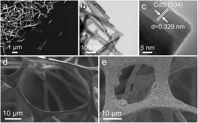 | ||
| Fig. 1 (a) SEM image, (b) TEM image and (c) HRTEM image of 1NC; (d) and (e) SEM images of AMS and 1NC/AMS. | ||
XPS analysis was carried out to study the surface chemical composition and electronic structure of the photocatalysts. These spectra, shown in Fig. S4,† are all calibrated according to the binding energy of graphitic carbon (C–C, 284.8 eV). The XPS survey measurement spectrum of 1NC shows the presence of Cd, S and Ni elements (Fig. S4a†), which is in accordance with the result of the EDX analysis. For the Cd 3d spectrum of pure CdS, the two evident peaks located at 404.6 and 411.3 eV can be assigned to Cd 3d5/2 and Cd 3d3/2, respectively (Fig. S4b†). In the S 2p high-resolution XPS spectrum, S 2p3/2 and S 2p1/2 at the binding energies of 161.0 and 162.2 eV are the typical features of sulfide ions in CdS (Fig. S4c†).44,45 For the Ni 2p high-resolution XPS spectrum, the two peaks appearing at 856.2 and 873.9 eV are contributed to by the binding energies of Ni 2p3/2 and Ni 2p1/2, respectively (Fig. S4d†).45 Additionally, compared to the XPS spectra of pure CdS, the peaks of Cd 3d and S 2p for 1NC moving towards higher binding energies indicate that electrons transfer from CdS to Ni atoms/clusters at the interface (Fig. S4b and c†), which is mainly ascribed to their strong interfacial interaction.
The photocatalytic hydrogen evolution performance of these photocatalysts was evaluated using triethanolamine as a sacrificial reagent under light illumination. In the traditional solid–liquid–gas triphase system, the photocatalytic hydrogen evolution rate of 1NC is 129.24 μmol h−1, which is 7.36 times that of CdS (Fig. S5†). It is well known that the effective separation of photogenerated charges is crucial to the photocatalytic activity, which can be explored from the perspective of charge carrier dynamics. The steady/transient-state photoluminescence (PL) emission spectra of the as-prepared samples are shown in Fig. S6.† Compared with pure CdS, the 1NC sample shown in Fig. S6a† reveals obvious PL quenching due to the rapid transfer of electrons from CdS to nickel atoms/clusters, indicating the inhibition of photogenerated carrier recombination. Moreover, the time-resolved transient PL decay spectra show a longer average lifetime (τavg) of charge carriers of 1NC with respect to the pure CdS (Fig. S6b and Table S1†), suggesting a more efficient charge transfer for 1NC.46,47 This consistent conclusion can also be supported by the photoelectric response upon repeated on/off illumination cycles (Fig. S7a†). Clearly, the transient photocurrent density of 1NC is much higher than that of pure CdS, again providing reasonable evidence for the introduction of nickel atoms/clusters to promote the charge transfer. The EIS Nyquist plot of 1NC has a smaller arc radius in comparison to that of pure CdS (Fig. S7b†), indicating that it has smaller charge transfer resistance. In summary, the introduction of highly dispersed nickel atoms/clusters on CdS leads to the prolongation of charge lifetime and the boosted separation of photogenerated charges, which is conducive to improving the photocatalytic activity.
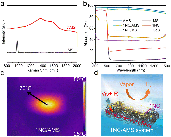
Inspired by the photothermal effect to further improve the photocatalytic performance of CdS and 1NC, we fabricated a gas–solid photocatalytic reaction system that can decouple hydrogen generation from a traditional solid–liquid interface. The black AMS was obtained by annealing original white MS in air at 400 °C for 1 hour (Fig. S8†). The original MS has a highly porous network structure with uniform pores (Fig. S9a†). The prepared AMS still maintains an obvious porous network structure but with reduced pore size after annealing (Fig. S9b†), and the volume shrinkage of AMS is about 60% compared to the original MS. The photocatalyst/AMS system was constructed by uniformly coating the surface of AMS with a mixed solution containing PVDF and photocatalyst. The addition of PVDF ensures that the photocatalyst adheres to the skeleton of the AMS surface uniformly and avoids falling to the bottom of the AMS as well. SEM images show that 1NC nanorods are uniformly attached to the smooth porous skeleton of AMS after the solution-dropping procedure (Fig. 1d and e). The elemental mapping distribution images of 1NC/AMS also reveal that Cd, S and Ni elements are homogeneously dispersed on the AMS skeleton (Fig. S10†). The XRD patterns of AMS, 1NC and 1NC/AMS are shown in Fig. S11,† again confirming the successful loading of 1NC nanomaterials onto AMS. As shown in Fig. S12,† SEM images of the CdS/AMS system with different magnifications further indicate that the photocatalyst has been successfully coated on the surface of AMS. Besides, Fig. 2a shows the Raman spectra of the original MS and AMS. For the original MS, the intense peak at 978 cm−1 is the characteristic peak of the breathing vibrational modes of the triazine ring in melamine, which is consistent with spectra in previous reports.48 After annealing at 400 °C for 1 h, the peak located at 978 cm−1 disappears and two new peaks assigned to the carbon D-band and G-band appeared. The G-band around 1580 cm−1 is the feature of graphitic layers, while the D-band around 1350 cm−1 corresponds to disordered carbon or defective graphitic structures.49,50 In addition, in the XRD spectrum of AMS, the broad peak between 20° and 30° indicates that AMS contains semi-ordered carbon (Fig. S11†).38 These results indicate that the original MS is successfully carbonized.
To evaluate the light absorption capacity of these samples, the absorption spectra were recorded over a range of 300 to 1500 nm, as shown in Fig. 2b. First of all, compared with pristine CdS, the absorption of visible light and infrared light in 1NC can be enhanced with the addition of nickel atoms/clusters. Second, compared with MS, AMS has stronger broadband absorption of sunlight with an absorbency of near to 100%. As shown in Fig. S13,† the surface temperature of AMS can be stabilized at about 125 °C under one-sun illumination in air, indicating the strong photothermal effect of AMS compared with the original MS. Third, the 1NC/AMS system exhibits excellent light absorption similar to that of pure AMS in the wavelength range of 300 to 1500 nm, indicating that our constructed system can make full use of sunlight. After a few minutes of light illumination, the temperature of the 1NC/AMS system stabilizes at about 70 °C due to the balance between the heat energy generated by the absorption of sunlight and the heat energy consumed by the evaporation of liquid water (Fig. 2c). In addition, we accurately measured the surface temperature of the 1NC/AMS system during photocatalytic hydrogen evolution using a thermocouple (Fig. S14†). In the first few minutes of light illumination, the surface temperature of 1NC/AMS rapidly increased and was maintained at about 70 °C thereafter, providing additional evidence for the above deduction. The detailed photocatalytic process based on this gas–solid photocatalytic reaction system by decoupling hydrogen generation from a traditional solid–liquid interface is illustrated in Fig. 2d. At the beginning, AMS converts liquid water into water vapor through the photothermal effect under light illumination, and then 1NC photocatalysts decompose the vapor into hydrogen.
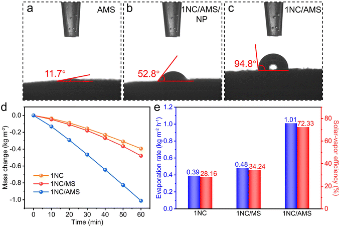
To further research the surface wettability of these prepared samples, contact angle measurements were carried out. Obviously, the smaller contact angle contributed by AMS reveals the superhydrophilicity of its surface (Fig. 3a). The highly porous structure together with excellent hydrophilicity of AMS ensures the continuous supply of water to the hot zone, contributing to enhancing the photothermal evaporation. In the absence of PVDF, the surface of the 1NC/AMS system still exhibits admirable hydrophilicity (Fig. 3b), which indicates that the 1NC photocatalyst can effectively adsorb gaseous water molecules and decompose them into hydrogen. The surface of the 1NC/AMS system shown in Fig. 3c becomes weakly hydrophobic due to the addition of PVDF, which can prevent excessive liquid water coming into contact with the photocatalyst and facilitate the release of vapor. In order to ensure sufficient vapor supply during the photocatalytic process, solar water evaporation test experiments were conducted under simulated sunlight illumination (AM 1.5G) conditions of one-sun intensity. The typical curves of mass change along with time for different systems under the same optical concentration are shown in Fig. 3d. Under light illumination, the water evaporation rates of 1NC, 1NC/MS, and 1NC/AMS were found to be 0.39, 0.48 and 1.01 kg m−2 h−1, corresponding to solar–vapor conversion efficiencies of 28.16%, 34.24%, and 72.33%, respectively (Fig. 3e). These results prove that the 1NC/AMS system can provide sufficient vapor to support the photocatalytic process.
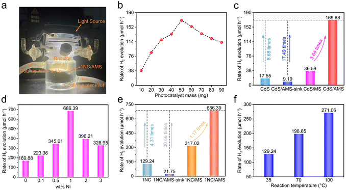
The hydrogen evolution device of the gas–solid photocatalytic reaction system is shown in Fig. 4a. It is obvious that the total reactor is filled with vapor under light illumination, which demonstrates the successful construction of the desired decoupling system. Accordingly, we first investigated the effect of CdS load mass on the photocatalytic hydrogen evolution rate in the CdS /AMS system (Fig. 4b). The highest hydrogen evolution rate can be achieved when 50 mg of CdS is loaded, while further increasing the mass of photocatalyst leads to significantly decreased hydrogen evolution rates. Basically, as shown in Fig. S15,† excess photocatalyst will block the pores of AMS and weaken the photothermal effect of AMS, thus inhibiting the release of vapor. In this case, the achieved hydrogen evolution rate of CdS/AMS can be 169.88 μmol h−1, an improvement of 8.68 times compared to the triphase CdS nanorods system (Fig. 4c). Notably, when the CdS/AMS system is completely immersed in water, the hydrogen evolution rate only remains at 9.19 μmol h−1, which can be explained by the significant barrier caused by hydrogen bubble desorption in water. In addition, compared with CdS/AMS, the hydrogen evolution rate of CdS/MS can be decreased to 36.59 μmol h−1 due to the weak light absorption of MS. After 3 hours of light illumination, no hydrogen evolution signal was detected on AMS (Fig. S16†), confirming that the photocatalytic activity of AMS can be ignored.
A comparison of hydrogen evolution rates of xNC/AMS systems with different Ni contents is shown in Fig. 4d. When the Ni loading on CdS is 1 wt%, the hydrogen evolution rate can reach the highest value of 686.39 μmol h−1. The hydrogen evolution rates of the triphase 1NC nanorods system, 1NC/AMS-sink system and 1NC/MS system are 129.24, 21.75, and 317.02 μmol h−1, respectively (Fig. 4e). The variation trend of hydrogen evolution rate under different systems is consistent with the results obtained from systems using pure CdS as the photocatalyst, verifying the universality of the decoupled photocatalysis system constructed in this study. The STH efficiency of this 1NC/AMS system is calculated to be 2.06%, compared to only 0.39% for the triphase 1NC nanorods system. In order to understand the proton source of 1NC/AMS reduction, D2O was used to replace H2O during the photocatalytic HER process. Due to the presence of the H/D isotope effect, the release rate of D2 decreases to 271.67 μmol h−1 under the same experimental conditions (Fig. S17†), indicating that the source of H2 is aqueous protons.51–53 In addition, the effect of temperature on photocatalytic hydrogen evolution activity based on this system was also investigated. It was found that without light illumination, hydrogen cannot be detected even if the reaction is maintained at 70 °C for a long time (Fig. S18†), confirming that the photocatalytic reaction cannot be triggered by heat. Under light illumination, as the temperature increases from 35 °C to 100 °C, the hydrogen evolution rate can be increased from 129.24 μmol h−1 to 271.06 μmol h−1 (Fig. 4f), and the enhancement of photocatalytic performance at higher temperature is consistent with previous reports.54 It is worth noting that even if the temperature of the triphase 1NC nanorods system is raised to 100 °C, the photocatalytic hydrogen evolution rate is still far lower than that of the 1NC/AMS system, which indicates that temperature is not a determinative factor in improving the photocatalytic activity of the 1NC/AMS system. The photocatalytic hydrogen evolution rates of the triphase CdS nanorods system at different temperatures can also serve as additional evidence to support the above conclusions (Fig. S19†). Thus, it is safe to say that the conversion of liquid water to vapor plays a decisive role in enhancing the hydrogen evolution of this decoupled photocatalytic reaction system.
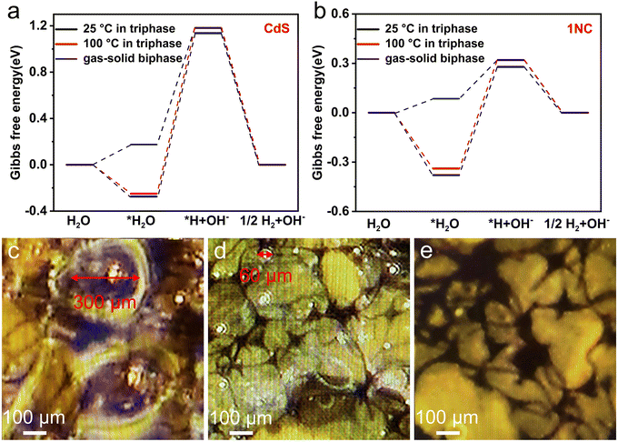
In order to further understand the underlying mechanism of enhanced photocatalytic hydrogen evolution by this gas–solid photocatalytic reaction system, DFT calculations of the Gibbs free energy of the H2 evolution reaction (HER) were carried out. Generally, the HER involves three reaction steps: the adsorption of water molecules, the adsorption of hydrogen atoms and the generation of hydrogen. The calculation models for the optimal adsorption configurations of water molecules and hydrogen atoms on CdS and 1NC are shown in Fig. S20 and Fig. S21.† For a better comparison, the Gibbs free energy of the CdS and 1NC triphase system working on two temperature levels of 25 °C and 100 °C has been calculated (Fig. 5a and b). In the CdS and 1NC triphase system, the Gibbs free energy of the adsorption process of water molecules at 100 °C (−0.249 and −0.339 eV) is lower than that at 25 °C (−0.274 and −0.379 eV), indicating that the high reaction temperature is thermodynamically conducive to the adsorption of water molecules on the photocatalyst. Meanwhile, high temperature can kinetically promote the transport of water molecules and reduce the transport resistance of hydrogen.26 It is notable that the largest increase of Gibbs free energy (the rate-limiting step) occurs in the water decomposition step where water in its adsorbed state (*H2O) acquires an electron and is reduced to protonic hydrogen (*H). It is obvious that the Gibbs free energy barrier of the rate-limiting step is significantly reduced after the modification of CdS by Ni, demonstrating that the successful construction of the 1NC composite photocatalyst is of great significance for activating the H–OH bond of adsorbed water by reducing the apparent activation energy of water splitting.55 Furthermore, the Gibbs free energy barrier of the rate-limiting step significantly decreases from 0.659 eV to 0.235 eV when the hydrogen evolution reaction changes from the solid–liquid–gas triphase at 100 °C to the gas–solid biphase (Fig. 5b), indicating that the decomposition process of gaseous water in the biphase system is smoother than that of liquid water in the triphase system, leading to the accelerated photocatalytic hydrogen evolution reaction.
In addition, from the perspective of the reaction kinetics between the photocatalytic reaction interface and the liquid phase system, the nucleation, growth, and desorption processes of bubbles play significant and complex roles in the whole photocatalytic process. Generally, the bubbles dispersed on the surface of the catalyst and reaction system can weaken the intensity of light illumination and affect the absorption of light by photocatalysts through their scattering and reflection characteristics. Second, the bubbles generated on the surface of the photocatalyst are subjected to the pressure of the surrounding liquid system as well as the adsorption force of the photocatalyst. These active sites of the photocatalyst cannot come into contact with the liquid phase system when the bubbles cannot be desorbed from the surface of the photocatalyst to the external system, thus limiting the adsorption of water molecules and photocatalysts and reducing the rate of photocatalytic hydrogen evolution.25 In order to further investigate the desorption of bubbles during photocatalysis, bubbles on the surface of 1NC/AMS immersed at different depths below the liquid level of water were accurately observed in situ under a high-resolution microscope. When the surface of 1NC/AMS is 5 mm away from the liquid level of water, the diameter of bubbles on the surface of 1NC/AMS is about 300 μm (Fig. 5c). Interestingly, the diameter of bubbles on the surface of 1NC/AMS can be decreased to about 60 μm when this distance is reduced to 1 mm (Fig. 5d). This is because as the height of liquid water into which the 1NC/AMS surface is immersed decreases, the bubbles generated by the photocatalytic hydrogen evolution reaction are subjected to less pressure from the surrounding liquid phase system. Correspondingly, it is not necessary for them to spend longer time growing into larger bubbles, and the buoyancy generated is sufficient to overcome the adsorption force of photocatalysts and the pressure of the surrounding liquid phase system to achieve desorption. Moreover, when the surface of 1NC/AMS is covered by vapor instead of liquid water, the formation of bubbles on the surface of 1NC/AMS cannot be observed (Fig. 5e), indicating a lower hydrogen transfer resistance in this system and timely contact between active sites of the photocatalyst with water molecules. These results clearly demonstrate that the 1NC/AMS system can provide a very favorable environment for the desorption of hydrogen bubbles at the active sites of photocatalysts, thus promoting the smooth process of the photocatalytic hydrogen evolution reaction. In short, in our study, the efficient photothermal materials manufactured combined with reasonable reaction system design can realize the transformation of the photocatalytic reaction system from the solid–liquid–gas triphase to the gas–solid biphase, greatly reducing the transport resistance of hydrogen at the interface, lifting the mutual restriction between the reaction rate of the photogenerated electron interface and the rate of bubble desorption, and fundamentally changing the slow mass transfer process at the triphase photocatalytic interface.
Conclusions
In summary, we have constructed a photothermally induced gas–solid photocatalytic reaction system with high solar spectral utilization by using a novel xNC photocatalyst and low-cost AMS as solar vapor generator. The new-type 1NC/AMS system achieves an excellent hydrogen evolution rate of 686.39 μmol h−1, 5.31 times that of the traditional solid–liquid–gas triphase system, with the corresponding STH efficiency being up to 2.06%. Compared with the triphase system, this biphase system reduces the Gibbs free energy barrier of the HER thermodynamically, greatly reduces the hydrogen transport resistance at the interface kinetically, avoids the formation of photocatalytic bubbles at the solid–liquid interface, and fundamentally changes the slow mass transfer and conversion process at the triphase photocatalytic interface. This work provides a new strategy to improve the performance of photocatalytic reactions by establishing a new-type reaction system for accelerating the mass transfer and conversion.Author contributions
Maochang Liu conceived and supervised this project. Shidong Zhao, Shujian Wang and Kejian Lu implemented the catalyst synthesis, characterization methods and photocatalytic measurements. Chunyang Zhang carried out the DFT calculations. Shidong Zhao and Maochang Liu wrote the manuscript. All authors discussed the obtained results and contributed to this manuscript.Conflicts of interest
There are no conflicts to declare.Acknowledgements
This work was supported by the National Key Research and Development Program of China (2022YFB3803600), the National Natural Science Foundation of China (No. 52276212), the Natural Science Foundation of Jiangsu Province (No. BK20231211), the Suzhou Science and Technology Program (SYG202101), the Zhuhai Innovation and Entrepreneurship Team Project (No. 2120004000225), the Key Research and Development Program of Shaanxi (Program No. 2023-YBGY-300), and the China Fundamental Research Funds for the Central Universities.References
- J. Q. Zhao, Y. Bai, Z. H. Li, J. J. Liu, W. Wang, P. Wang, B. Yang, R. Shi, G. I. N. Waterhouse, X. D. Wen, Q. Dai and T. R. Zhang, Angew. Chem., Int. Edit., 2023, 62, e202219299 CrossRef CAS PubMed.
- Z. H. Li, J. J. Liu, J. Q. Zhao, R. Shi, G. I. N. Waterhouse, X. D. Wen and T. R. Zhang, Adv. Funct. Mater., 2023, 33, 2213672 CrossRef CAS.
- L. Shang, B. A. Tong, H. J. Yu, G. I. N. Waterhouse, C. Zhou, Y. F. Zhao, M. Tahir, L. Z. Wu, C. H. Tung and T. R. Zhang, Adv. Energy Mater., 2016, 6, 1501241 CrossRef.
- S. Q. Zhang, G. Cheng, L. P. Guo, N. Wang, B. E. Tan and S. B. Jin, Angew. Chem., Int. Edit., 2020, 59, 6007–6014 CrossRef CAS PubMed.
- B. Y. Dai, Y. R. Yu, Y. K. Chen, H. M. Huang, C. H. Lu, J. H. Kou, Y. J. Zhao and Z. Z. Xu, Adv. Funct. Mater., 2019, 29, 1807934 CrossRef.
- Q. Wang, M. Nakabayashi, T. Hisatomi, S. Sun, S. Akiyama, Z. Wang, Z. H. Pan, X. Xiao, T. Watanabe, T. Yamada, N. Shibata, T. Takata and K. Domen, Nat. Mater., 2019, 18, 827 CrossRef CAS PubMed.
- J. Liu, Y. Liu, N. Y. Liu, Y. Z. Han, X. Zhang, H. Huang, Y. Lifshitz, S. T. Lee, J. Zhong and Z. H. Kang, Science, 2015, 347, 970–974 CrossRef CAS PubMed.
- T. Hisatomi and K. Domen, Nat. Catal., 2019, 2, 387–399 CrossRef CAS.
- Y. Y. Li, Y. K. Peng, L. S. Hu, J. W. Zheng, D. Prabhakaran, S. Wu, T. J. Puchtler, M. Li, K. Y. Wong, R. A. Taylor and S. C. E. Tsang, Nat. Commun., 2019, 10, 4421 CrossRef PubMed.
- R. Shi, Y. H. Cao, Y. J. Bao, Y. F. Zhao, G. I. N. Waterhouse, Z. Y. Fang, L. Z. Wu, C. H. Tung, Y. D. Yin and T. R. Zhang, Adv. Mater., 2017, 29, 1700803 CrossRef PubMed.
- Q. Wang and K. Domen, Chem. Rev., 2020, 120, 919–985 CrossRef CAS PubMed.
- M. C. Liu, D. W. Jing, Z. H. Zhou and L. J. Guo, Nat. Commun., 2013, 4, 2278 CrossRef PubMed.
- H. J. Yu, R. Shi, Y. X. Zhao, T. Bian, Y. F. Zhao, C. Zhou, G. I. N. Waterhouse, L. Z. Wu, C. H. Tung and T. R. Zhang, Adv. Mater., 2017, 29, 1605148 CrossRef PubMed.
- L. Wang, Y. Zhang, L. Chen, H. X. Xu and Y. J. Xiong, Adv. Mater., 2018, 30, 1801955 CrossRef PubMed.
- Y. O. Wang, H. Suzuki, J. J. Xie, O. Tomita, D. J. Martin, M. Higashi, D. Kong, R. Abe and J. W. Tang, Chem. Rev., 2018, 118, 5201–5241 CrossRef CAS PubMed.
- D. M. Zhao, Y. Q. Wang, C. L. Dong, Y. C. Huang, J. Chen, F. Xue, S. H. Shen and L. J. Guo, Nat. Energy, 2021, 6, 388–397 CrossRef CAS.
- M. S. Zhu, Z. C. Sun, M. Fujitsuka and T. Majima, Angew. Chem., Int. Edit., 2018, 57, 2160–2164 CrossRef CAS PubMed.
- S. T. Wan, H. T. Li, Z. H. Ma, H. C. Zhang and Y. Z. Zheng, Rare Met., 2022, 41, 1735–1742 CrossRef CAS.
- M. C. Liu, Y. B. Chen, J. Z. Su, J. W. Shi, X. X. Wang and L. J. Guo, Nat. Energy, 2016, 1, 16151 CrossRef CAS.
- A. Indra, A. Acharjya, P. W. Menezes, C. Merschjann, D. Hollmann, M. Schwarze, M. Aktas, A. Friedrich, S. Lochbrunner, A. Thomas and M. Driess, Angew. Chem., Int. Edit., 2017, 56, 1653–1657 CrossRef CAS PubMed.
- Z. J. Han, F. Qiu, R. Eisenberg, P. L. Holland and T. D. Krauss, Science, 2012, 338, 1321–1324 CrossRef CAS PubMed.
- R. M. Pope and E. S. Fry, Appl. Opt., 1997, 36, 8710–8723 CrossRef CAS PubMed.
- Z. Y. Lin, J. L. Li, Z. Q. Zheng, L. H. Li, L. L. Yu, C. X. Wang and G. W. Yang, Adv. Energy Mater., 2016, 6, 1600510 CrossRef.
- P. A. Kempler, Z. P. Ifkovits, W. L. Yu, A. I. Carim and N. S. Lewis, Energy Environ. Sci., 2021, 14, 414–423 RSC.
- M. L. Sun, L. Zhou, T. G. Dong, H. M. Huang, Z. G. Fang, J. H. Kou, C. H. Lu and Z. Z. Xu, ACS Appl. Mater. Interfaces, 2021, 13, 21207–21216 CrossRef CAS PubMed.
- S. H. Guo, X. H. Li, J. Li and B. Q. Wei, Nat. Commun., 2021, 12, 1343 CrossRef CAS PubMed.
- Y. J. Wang, W. J. Huang, S. H. Guo, X. Xin, Y. Z. Zhang, P. Guo, S. W. Tang and X. H. Li, Adv. Energy Mater., 2021, 11, 2102452 CrossRef CAS.
- Y. X. Tang, Z. L. Jiang, G. C. Xing, A. R. Li, P. D. Kanhere, Y. Y. Zhang, T. C. Sum, S. Z. Li, X. D. Chen, Z. L. Dong and Z. Chen, Adv. Funct. Mater., 2013, 23, 2932–2940 CrossRef CAS.
- X. N. Wang, F. L. Wang, Y. H. Sang and H. Liu, Adv. Energy Mater., 2017, 7, 1700473 CrossRef.
- B. Y. Dai, J. J. Fang, Y. R. Yu, M. L. Sun, H. M. Huang, C. H. Lu, J. H. Kou, Y. J. Zhao and Z. Z. Xu, Adv. Mater., 2020, 32, 1906361 CrossRef CAS PubMed.
- J. Li, X. Y. Wu, W. F. Pan, G. K. Zhang and H. Chen, Angew. Chem., Int. Edit., 2018, 57, 491–495 CrossRef CAS PubMed.
- F. Chen, L. L. Liu, Y. J. Zhang, J. H. Wu, G. X. Huang, Q. Yang, J. J. Chen and H. Q. Yu, Appl. Catal., B, 2020, 277, 119218 CrossRef CAS.
- M. Li, J. X. Sun, G. Chen, S. Y. Yao, B. W. Cong and P. F. Liu, Appl. Catal., B, 2021, 298, 120573 CrossRef CAS.
- H. Y. Ren, M. Tang, B. L. Guan, K. X. Wang, J. W. Yang, F. F. Wang, M. Z. Wang, J. Y. Shan, Z. L. Chen, D. Wei, H. L. Peng and Z. F. Liu, Adv. Mater., 2017, 29, 1702590 CrossRef PubMed.
- F. Jiang, T. Li, Y. J. Li, Y. Zhang, A. Gong, J. Q. Dai, E. Hitz, W. Luo and L. B. Hu, Adv. Mater., 2018, 30, 1703453 CrossRef PubMed.
- M. W. Zhu, Y. J. Li, G. Chen, F. Jiang, Z. Yang, X. G. Luo, Y. B. Wang, S. D. Lacey, J. Q. Dai, C. W. Wang, C. Jia, J. Y. Wan, Y. G. Yao, A. Gong, B. Yang, Z. F. Yu, S. Das and L. B. Hu, Adv. Mater., 2017, 29, 1704107 CrossRef PubMed.
- F. Gong, H. Li, W. B. Wang, J. G. Huang, D. W. Xia, J. X. Liao, M. Q. Wu and D. V. Papavassiliou, Nano Energy, 2019, 58, 322–330 CrossRef CAS.
- L. L. Zhu, M. M. Gao, C. K. N. Peh, X. Q. Wang and G. W. Ho, Adv. Energy Mater., 2018, 8, 1702149 CrossRef.
- L. F. Cui, P. F. Wang, H. A. Che, X. Gao, J. Chen, B. Liu and Y. H. Ao, Water Res., 2023, 244, 120514 CrossRef CAS PubMed.
- L. F. Cui, P. F. Wang, H. A. Che, X. Gao, J. Chen, B. Liu and Y. H. Ao, Appl. Catal., B, 2023, 330, 122556 CrossRef CAS.
- L. F. Cui, C. W. Ma, P. F. Wang, H. A. Che, H. L. Xu and Y. H. Ao, Appl. Catal., B, 2023, 337, 122988 CrossRef CAS.
- J. H. Li, L. L. Ding, Z. Y. Su, K. Li, F. Fang, R. X. Sun, Y. L. Qin and K. Chang, Adv. Mater., 2023, 2305535 CrossRef CAS PubMed.
- J. S. Jang, U. A. Joshi and J. S. Lee, J. Phys. Chem. C, 2007, 111, 13280–13287 CrossRef CAS.
- H. Z. Zhang, Y. M. Dong, S. Zhao, G. L. Wang, P. P. Jiang, J. Zhong and Y. F. Zhu, Appl. Catal., B, 2020, 261, 118233 CrossRef CAS.
- Z. J. Sun, H. F. Zheng, J. S. Li and P. W. Du, Energy Environ. Sci., 2015, 8, 2668–2676 RSC.
- B. Lin, G. D. Yang and L. Z. Wang, Angew. Chem., Int. Edit., 2019, 58, 4587–4591 CrossRef CAS PubMed.
- M. M. Hao, Y. Bai, S. Zeiske, L. Ren, J. X. Liu, Y. B. Yuan, N. Zarrabi, N. Y. Cheng, M. Ghasemi, P. Chen, M. Q. Lyu, D. X. He, J. H. Yun, Y. Du, Y. Wang, S. S. Ding, A. Armin, P. Meredith, G. Liu, H. M. Cheng and L. Z. Wang, Nat. Energy, 2020, 5, 79–88 CrossRef CAS.
- X. F. Lin, J. Y. Chen, Z. K. Yuan, M. J. Yang, G. J. Chen, D. S. Yu, M. Q. Zhang, W. Hong and X. D. Chen, J. Mater. Chem. A, 2018, 6, 4642–4648 RSC.
- Y. W. Zhang, J. Ge, L. Wang, D. H. Wang, F. Ding, X. M. Tao and W. Chen, Sci. Rep., 2013, 3, 2771 CrossRef PubMed.
- M. Marton, M. Vojs, E. Zdravecka, M. Himmerlich, T. Haensel, S. Krischok, M. Kotlar, P. Michniak, M. Vesely and R. Redhammer, J. Spectrosc., 2013, 2013, 467079 Search PubMed.
- X. L. Wang, W. Q. Liu, Y. Y. Yu, Y. H. Song, W. Q. Fang, D. X. Wei, X. Q. Gong, Y. F. Yao and H. G. Yang, Nat. Commun., 2016, 7, 11918 CrossRef CAS PubMed.
- J. W. Fang, T. Debnath, S. Bhattacharyya, M. Döblinger, J. Feldmann and J. K. Stolarczyk, Nat. Commun., 2020, 11, 5179 CrossRef CAS PubMed.
- Y. Guo, Q. X. Zhou, J. Nan, W. X. Shi, F. Y. Cui and Y. F. Zhu, Nat. Commun., 2022, 13, 2067 CrossRef CAS PubMed.
- R. Song, B. Luo, J. F. Geng, D. X. Song and D. W. Jing, Ind. Eng. Chem. Res., 2018, 57, 7846–7854 CrossRef CAS.
- Y. C. Guo, L. Mao, Y. Tang, Q. Q. Shang, X. Y. Cai, J. Y. Zhang, H. L. Hu, X. Tan, L. Q. Liu, H. Y. Wang, T. Yu and J. H. Ye, Nano Energy, 2022, 95, 107028 CrossRef CAS.
Footnotes |
| † Electronic supplementary information (ESI) available. See DOI: https://doi.org/10.1039/d3nr04937j |
| ‡ These authors contributed equally to this manuscript. |
| This journal is © The Royal Society of Chemistry 2024 |

